

Page 1

DPG 1000DR
Digital Pressure Gauge
USER’S GUIDE
www.cooperinstruments.com
PH: 540 -349-4746 • FAX: 540-347-4755
Page 2
Installation and Precautions
Install or remove the gauge-using wrench on hex fitting only. Do not attempt to tighten by turning housing or
any other part of the gauge. Use fittings appropriate for the pressure range of the gauge. Do not apply
vacuum to gauges not designed for vacuum operation. Due to the hardness of 316 stainless steel, it is
recommended that a thread sealant be used to ensure leak -free operation.
NEVER insert objects into the gauge port or blow out with compressed air. Permanent damage not covered
by warranty will result to the sensor.
Electrical Connection
NEVER connect the gauge wires directly to 115 VAC or permanent damage not covered by warranty will
result.
The DPG1000DR and DPG1000DRBL can be powered by any 9 to 32 VDC or 8 to 24 VAC 50/60 Hz power
source. An inexpensive unregulated low voltag e source can be used. The magnitude of the supply voltage
has negligible effect on the gauge calibration as long as it is within the stated voltage ranges. Do not allow
the gauge supply voltage fall below 9 VDC or 8 VAC RMS. Operation below these values may cause erratic
or erroneous readings or output. Models with 4-20 mA output power the current loop. Use a power source
with sufficient voltage to operate the current loop.
Connection is made with the 4-conductor cable at the gauge rear. This cable accommodates both the gauge
power supply and retransmission output. This cable has one RED and one BLACK lead. If using a 9 to 32
VDC power source, connect the (+) supply to the RED lead and the (–) supply to the BLACK lead. If using a
8 to 24 VAC 50/60 Hz power source, connect to the RED and BLACK leads. When using low voltage AC
power, there is of course, no polarity consideration.
The (+) retransmission output appears on the WHITE lead, and the (–) retransmission output appears on the
GREEN lead. Use of the shield (drain) wire of the retransmission output is optional. It is not generally needed
for 4-20 mA current loops unless very long cable lengths are used in electrically noisy environments.
The output is a continuous analog signal based on the transducer output rather than the display. This output
is filtered to improve noise immunity and has a response time of about 50 milliseconds.
The power supply (–) lead is tied to the retransmission output ground. Therefore, if a DC supply is used, the
power supply (–) lead should be considered common with regard to the retransmission output (–) connection.
Using the Retransmission Output
NEVER connect retransmission output wires together
or to an external power source or permanent damage
not covered by warranty will result.
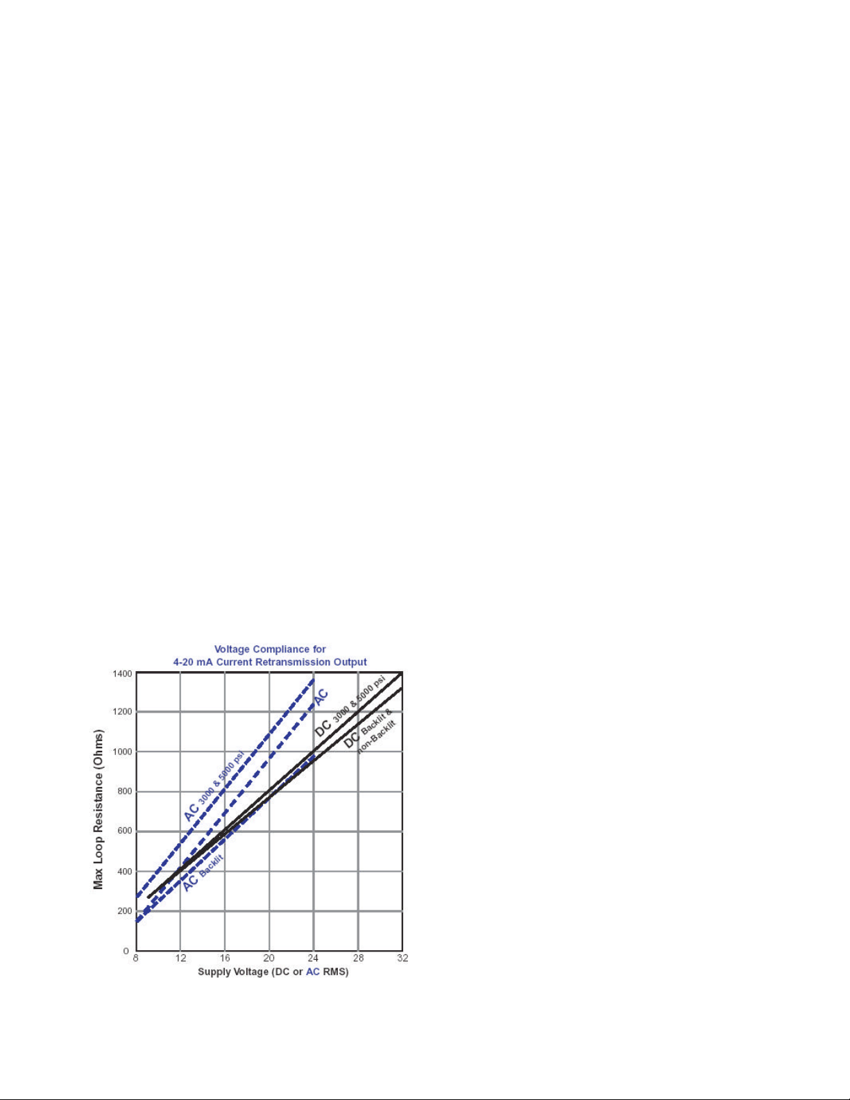
For 4-20 mA output models, be sure to observe the
output compliance (voltage drive) capabilities of the
gauge. The compliance, and therefore the maximum
loop resistance the output can drive, is a function of
the supply voltage to the gauge. Consult the graph
shown at right for maximum loop resistance vs.
gauge supply voltage. Too large a loop resistance will
cause the gauge output to “limit” or saturate before
reaching its full 20 mA output.
When using the 0-2 volt retransmission output, do not
allow the resistive load on the output to fall below 5K
ohms. Also, avoid large capacitive loads (greater that
1000 pF) such as those caused by long runs of
shielded cable. For long retransmission runs, use the
4-20 mA output model instead.
CF 144 1 DPG 1000DR
Page 3

Operation
The gauge is powered on whenever a supply voltage is applied. Warm -up time is negligible. In normal
operation, the system pressure is displayed on the gauge LCD and an output signal will be present.
DPG1000DRBL model display backlighting will be on whenever power is applied.
TEST Button
When the front -panel TEST button is held depressed, the display and retransmission output are switched,
independent of the system pressure, to a test level determined by the setting of the Test potentiometer. This
test mode will allow setup and testing of the output and any external device(s) connected to it by switching to
this test level whenever desired without having to alter the system pressure.
To set the test output level, see gauge label for location of Test potentiometer. Press and hold the front -panel
TEST button and adjust the Test potentiometer to set the display and retransmitted output to the desired test
level.
Calibration
See gauge label for location of controls to adjust the zero and span of the display.
GAUGE reference units may be re -zeroed without affecting the span calibration. The gauge port must be
open to the ambient with no pressure/vacuum applied. Adjust the Zero control until the gauge reads zero
with he minus (–) sign occasionally flashing.
Span calibration should only be attempted if the user has access to a pressure reference of known accuracy.
The quality of the calibration is only as good as the accuracy of the calibration equipment and ideally should
be at least four times the gauge accuracy. Zero calibration must be done before span calibration. Record
readings at three to five points over the range of gauge and adjust span control to minimize error and meet
specifications.
ABSOLUTE reference gauges require vacuum generation and atmospheric pressure measurement
equipment for accurate calibration and thus are more difficult to calibrate in the field. Gauges may be
returned to Cooper Instruments for factory certified recalibration. N.I.S.T. traceability is available.
Internal potentiometers adjust the agreement between the displayed value and the analog output. These are
set at the factory and should not normally be adjusted. If adjustment is required, consult factory. Accurate
pressure generation and measurement and current measurement equipment are required to successfully
complete this calibration.
CF 144 2 DPG 1000DR
Page 4

Part Numbers
Example: DPG1000DR100PSIG-I = DPG1000DR, 100.0 psig, Current (4-20 mA) retransmission
Unit Abbreviations
psi = PSI
inHg = INHG
oz/in2 = ZIN
inH2O = INH2O
ftH2O = FTH2O
mmHg = MMHG
torr = TORR
mmH2O = MMH2O
kg/cm2 = KGCM
g/cm2 = GCM
kPa = KPA
MPa = MPA
mbar = MBAR
bar = BAR
cmH2O = CMH2O
atm = ATM
CF 144 3 DPG 1000DR
 Loading...