

Page 1

DPG 100
DIGITAL PRESSURE GAGE
USER’S GUIDE
http://www.cooperinstruments.com
PH: (540)349-4746 • FAX: (540)347-4755
Page 2

CONTENTS
CHAPTER 1 GETTING STARTED...........................................................................................1
1.1 Quick Start Guide ...................................................................................................................... 1
1.2 About This Manual ...................................................................................................................1
CHAPTER 2 INTRODUCTION .................................................................................................1
2.1 Overview ....................................................................................................................................1
2.2 Instrument Layout ..................................................................................................................... 1
2.2.1 LCD Display .......................................................................................................................1
2.2.2 Low Battery Indicator........................................................................................................2
2.2.3 Decimal Point Position...................................................................................................... 2
2.2.4 Incremental Display Step..................................................................................................2
2.2.5 Pressure Port Threads ...................................................................................................... 2
2.3 Maximum Safe Overpressure...................................................................................................2
2.4 Front and Side Views ................................................................................................................ 3
2.5 Dimensions ................................................................................................................................ 4
2.6 Specifications ............................................................................................................................ 5
2.7 Accessories ...............................................................................................................................5
CHAPTER 3 SET UP................................................................................................................6
3.1 Installation .................................................................................................................................6
3.2 Front Panel Rotation ................................................................................................................. 6
3.3 Power Supply Options .............................................................................................................. 7
3.3.1 Battery ................................................................................................................................7
3.3.2 AC Adapter.........................................................................................................................7
3.3.3 External Vehicle (DC) Power Supply ...............................................................................7
3.4 Turning the Instrument On and Off .........................................................................................7
3.5 Zeroing the Display ................................................................................................................... 7
3.6 Restoring the Calibrated Zero..................................................................................................8
3.7 Reading the High/low Values ...................................................................................................8
3.8 Clearing the High/low Values ................................................................................................... 8
CHAPTER 4 CALIBRATION....................................................................................................8
4.1 Calibration Considerations ......................................................................................................8
4.2 Required Pressures ..................................................................................................................9
4.3 Calibration Procedure...............................................................................................................9
4.4 Rear View of Front Face Panel...............................................................................................10
4.5 Calibration Error Messages.................................................................................................... 11
CHAPTER 5 OUPUT SIGNALS .............................................................................................11
5.1 Output Signal Overview..........................................................................................................11
5.2 Specifications .......................................................................................................................... 11
5.2.1 Limit Relay Option...........................................................................................................11
5.2.2 0-5 VDC Output ................................................................................................................ 11
5.2.3 2-wire 4-20 mA Output ....................................................................................................11
5.3 Wiring Codes And Schematics ..............................................................................................12
5.3.1 Wiring To The Terminal Blocks......................................................................................12
5.3.2 Limit Option .....................................................................................................................13
5.3.3 0-5 VDC Output Option ...................................................................................................13
5.3.4 0-5 VDC Output And Limit Relay Option .......................................................................13
5.3.5 4-20 mA Output Option ...................................................................................................14
5.4 Explanation Of Limits .............................................................................................................14
5.5 Entering The Limit Setpoints .................................................................................................14
5.6 Trimming Of Analog Outputs .................................................................................................14
DPG 100 ii Rev Feb 2001
Page 3

CHAPTER 6 FIELD SELECTABLE FEATURES ...................................................................15
6.1 Introduction ...............................................................................................................................15
6.2 Setup Menu Operation ............................................................................................................15
6.3 Low Limit Setpoint ("L-LO") Menu Item ................................................................................17
6.4 High Limit Setpoint ("L-HI”) Menu Item.................................................................................17
6.5 Enable Options ("EO") Description .......................................................................................17
6.5.1 Auto-Off Feature .............................................................................................................. 17
6.5.2 Always-On Feature .......................................................................................................... 17
6.5.3 [Zero] Button Disable Feature ........................................................................................ 17
6.5.4 [Hi/Lo] Button Disable Feature.......................................................................................17
6.5.5 [Clear] Button Disable Feature.......................................................................................18
6.6 Enable Options ("EO") Menu Item .........................................................................................18
6.7 Engineering Units ("UNlT”) Menu Item..................................................................................18
6.8 Analog Output Zero Scale ("A-LO") Item ..............................................................................19
6.9 Analog Output Full Scale ("A-HI ") Menu Item...................................................................... 19
6.10 Internal Firmware Version ("VER") Menu Item ..................................................................... 19
CHAPTER 7 TROUBLESHOOTING ......................................................................................19
7.1 Introduction .............................................................................................................................19
7.2 Help Message Codes ..............................................................................................................19
7.3 Troubleshooting Hints ............................................................................................................ 20
CHAPTER 8 POWER ADAPTER SPECIFICATION ..............................................................20
CHAPTER 9 WARRANTY REPAIR POLICY.........................................................................21
DPG 100 iii Rev Feb 2001
Page 4

CHAPTER 1 GETTING STARTED
IMPORTANT! IT IS RECOMMENDED THAT YOU READ THIS DOCUMENT THOROUGHLY BEFORE
APPLYING POWER TO THIS UNIT. THIS DOCUMENT CONTAINS INFORMATION ON WIRING,
CALIBRATION, AND USE OF FEATURES.
1.1 Quick Start Guide
1. The instrument comes calibrated from the factory and needs no further calibration.
2. For battery powered instruments, install one or two alkaline batteries by removing the rear center screw
and then the front faceplate. See "Battery" in Section 3.3.
• If using an AC adapter, connect the adapter into the back of the instrument.
• If using a Vehicle powered or Loop powered instrument, use the wiring diagrams in Chapter 6.
3. Screw the instrument into place noting the correct threads. See "Installation" in Chapter 3.
• Up to and including 300 PSI = 1/4 18 NPT [Pipe thread] (3/4" Hex)
• Above 500 PSI = 9/16- 18 UNF [Straight thread] (7/8" Hex)
4. Push the [On/Off] button.
5. You are now ready to monitor pressure.
1.2 About This Manual
This is the User's Guide for standard Digital Pressure Gages. Other instruments may be made available with
additional features, pressure ports and other options. As the product is continually improved, the information herein
is subject to change without notice.
CHAPTER 2 INTRODUCTION
2.1 Overview
The Digital Pressure Test Gage combines the latest in pressure transducer technology with modern microprocessor
electronics to provide a high-accuracy digital readout of process pressure. Stainless-steel construction, high overpressure protection and a solid-state design give these instruments a long lifetime with fewer recalibrations.
An easy-to-read digital display provides four ½” digits. The waterproof membrane face uses raised buttons with
tactile feedback for ease of setup and operation. Zero adjustment, zero offset/tare, high, low and clear functions are
standard on each instrument. Calibration and setup information is stored in non-volatile memory to protect from loss
even when power is interrupted. Unauthorized calibrations are also blocked with internal security. Field-selectable
units of measure allow one instrument to be re-configured for a variety of tasks.
2.2 Instrument Layout
2.2.1 LCD Display
The four ½” digit liquid crystal display (LCD) readout displays the pressure applied to the instrument, interacts with
the user when the instrument is being set up or calibrated, and indicates if there is a problem with the instrument.
When the instrument is turned on, it illuminates all LCD segments. Then the engineering units the gauge will be
using appear on the display. Most instruments are calibrated in PSI and the instrument has conversion factors for
many standard engineering units built in. However, if the instrument displays SPCL (special), it has been specially
calibrated to another engineering unit at the factory. In that case, the serial number tag on the top of the instrument
will indicate the engineering units being used and the capability to select other engineering units is not available.
After the display of the engineering units, the pressure applied to the pressure port is shown on the display. If the
pressure applied to the pressure port is above the instrument's ability to measure, the display will indicate this over
range condition by showing a "1" on the far left hand side of the display. The display will read "-1" if the instrument
is under ranged.
DPG 100 1 Rev Feb 2001
Page 5

2.2.2 Low Battery Indicator
On the left side of the display, just above the minus sign, is the low battery indicator (in the shape of an arrow).
When the battery voltage is less than 5 volts, the display will be blanked and the low battery indicator will illuminate
to indicate that the batteries should be replaced. The low battery indicator can be seen when the instrument is
turned on and all segments of the display are momentarily lighted.
When the low battery indicator is illuminated, change the batteries as soon as possible. The instrument will not
function if the battery voltage falls below approximately 4 volts.
2.2.3 Decimal Point Position
The decimal point position automatically changes depending upon:
• the user selected engineering units
• the pressure range of the instrument
The decimal point position cannot be changed manually.
2.2.4 Incremental Display Step
The incremental display step is the value, which the last digit of the display will change by. This value will either be
1, 2, or 5 display counts. It automatically changes depending upon:
• the user selected engineering units
• the pressure range of the instrument
The incremental display step cannot be changed manually.
2.2.5 Pressure Port Threads
There are two types of pressure ports used, based on the operating pressure of the instrument. Male threads (for
ranges below 500 PSI) are ¼ -18 NPT. Female threads (for ranges 500 PSI and above) are 9/16-18 UNF-2B
straight thread with SAE spec J514 O-ring boss. An 0-ring is needed to seal all instruments with female threads.
Optional pressure adapters are listed in the "Accessories" section of this chapter.
2.3 Maximum Safe Overpressure
Maximum safe overpressure is the pressure that the instrument can experience occasionally without loss of
accuracy or permanent damage.
Table 1: Maximum Safe Overpressure
Pressure Range (PSI)
0-1=1 10
0 -5 = 5 25
0-15=15 75
0-30=30 150
0 -50 = 50 250
0-100=100 500
0-200 = 200 1000
0- 300 = 300 1200
0- 500 = 500 1500
0- 750 = 750 1500
0 -1000 = 1K 2000
0 -1500 = 1.5K 3000
0 -2000 = 2K 4000
0 -3000 = 3K 6000
0 -5000 = 5K 7500
0-7500 = 7.5K 12000
0-10000= 10K 15000
Maximum Safe
Overpressure (PSI)
DPG 100 2 Rev Feb 2001
Page 6
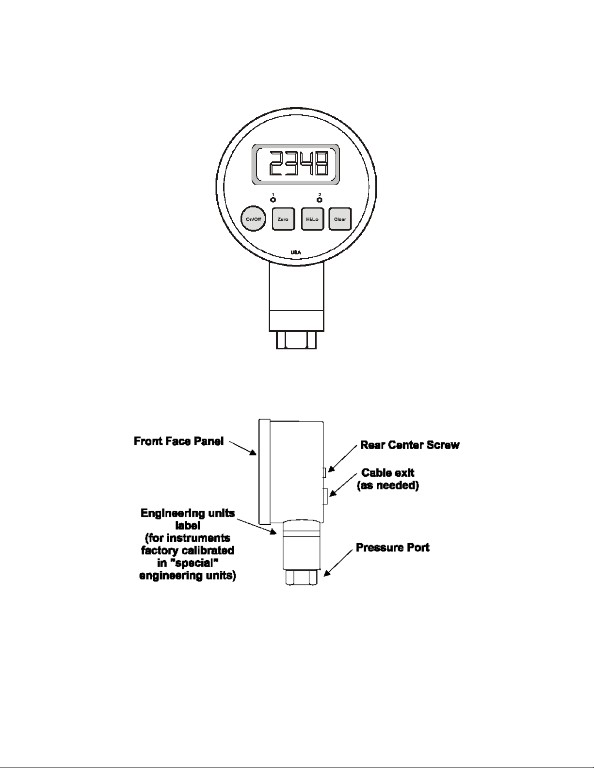
2.4 Front and Side Views
Figure 2-1: Front View
Figure 2-2: Side View
DPG 100 3 Rev Feb 2001
Page 7
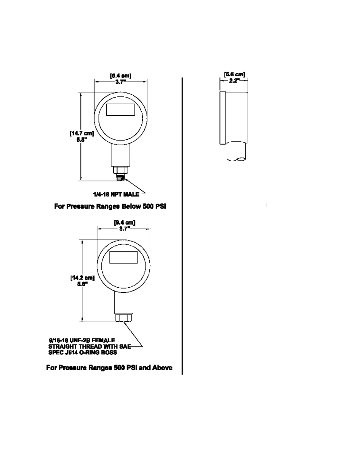
2.5 Dimensions
Figure 2-3: Dimensions
DPG 100 4 Rev Feb 2001
Page 8

2.6 Specifications
These specifications are subject to change without notice.
Enclosure Rating: NEMA 2 (standard),
NEMA 4 (optional; not available with AC Adapter
power)
Diameter: 3.7 inches
Linearity and Hysteresis: .2% of full-scale, linearity and hysteresis (better than
test gauge accuracy)
Operating Temperature: 30 to 160 °F (standard),
0 to 180 °F (with NEMA 4 option)
Pressure Ranges 0 to: 1, 5, 15, 30, 50, 100' 200, 300, 500, 750, 1K, 1.5K,
2K, 3K, 5K, 7.5K, 10K PSI
Calibration Engineering Units: PSI
Built-in Engineering Unit
Conversion:
Special Engineering Units: Optional
Display: 4 ½” LCD digits, 0.5 inches high
A-to-D converter sample rate: 7.8 kHz
Frequency Response ( -3dB): .78Hz
Display, Limits and Output
Update Rate:
Pressure Port: below 500 PSI:
Power Requirements: Battery Powered:
Wetted Parts: Stainless steel
Housing Material: Stainless steel
High and Low Capture: Standard, same update rate as display
Zero and Span Adjustment: Standard
Front Panel Membrane: Tactile feedback, raised buttons
Calibration Data: Stored on non-volatile memory chip
PSI, bar, mbar, inH
ftH2O (field selectable)
3 per second
1/4-18 NPT male
500 PSI and above:
9/16 -18 UNF-2B female with SAE spec J514 O-ring
boss
one or two 9 Volt alkaline batteries
AC Adapter Powered:
110 VAC@60 Hz adapter (included)
Vehicle (DC) Powered:
11 to 32 VDC (3 ft. cable included)
O, inHg, kPa, mmHG, MPa,
2
2.7 Accessories
PRESSURE ADAPTERS (Zinc Plated Steel)
To 1/4 -18 NPT female
To 1/4- 18 NPT male N/A
To 7/16- 20 UNF male with 37 degree flare
PRESSURE ADAPTERS (Stainless Steel)
To 1/4 -18 NPT female
To 1/4- 18 NPT male N/A
To 7/16- 20 UNF male with 37 degree flare
PANEL MOUNTING RING
CARRYING CASE
< 500 PSI
instruments
√ √
√ √
√ √
√ √
√ √
√ √
>= 500 PSI
instruments
√
√
DPG 100 5 Rev Feb 2001
Page 9

CHAPTER 3 SET UP
3.1 Installation
When installing the instrument into a process connection, make sure all backpressure is relieved from the system.
Make sure that you use the proper fitting to mate with the instrument.
To connect to the pressure fitting, use:
• 1/4-18 NPT for ranges below 500 PSI (3/4" hex wrench)
• 9/16-18 UNF-2B (straight thread) for ranges 500 PSI and above (7/ 8" hex wrench). An O-ring is needed to
seal the connection.
Failure to use the correct fitting will result in leaks. Always use the proper size wrench when tightening the
instrument into your system. NEVER attempt to tighten the unit by turning the round housing by hand or other
means. This may result in permanent damage to the instrument and will render the warranty void.
Figure 3-1: Always use a wrench
3.2 Front Panel Rotation
To allow for easy reading and operation regardless of the placement of the process connection, the front face panel
can be rotated up to 360 degrees with respect to the pressure port. To re-mount the front face panel into the
position of your choice:
• Remove the center screw on the back of the instrument.
• Remove the front face panel from the case.
• Rotate the front face panel into the desired position. Take care not to disconnect the sensor ribbon cable
from the electronics.
• Replace the front face panel. Do not crush or crimp the ribbon cable while replacing the front face panel.
• Carefully replace the rear center screw.
Figure 3-2: Illustration of Front Face Panel Rotation
DPG 100 6 Rev Feb 2001
Page 10

3.3 Power Supply Options
3.3.1 Battery
Two nine-volt alkaline batteries (NEDA 1604) are recommended operation. This is a common type of battery that is
available at many stores. With two alkaline batteries, the instrument can operate continuously on for approximately
3 weeks. Carbon-zinc batteries (sometimes labeled as "general purpose" or "heavy duty") should not be used.
Please note that the temperature specifications of the batteries you purchase may not be the same as those of the
instrument.
If two batteries are not available, the instrument will operate with only one alkaline battery installed in either clip.
However, this will reduce the continuous operation time to approximately one-and-a -half weeks.
The use of two lithium batteries will allow your instrument to operate continuously for over 6 weeks.
To install the batteries:
Important note
in the figure in Section 4.4. If you connect the sensor cable backwards, the instrument will not operate correctly.
• Remove the center screw on the back of the instrument.
• Remove the front face panel from the case.
• The colored ribbon cable extending from the sensor to the electronics may be disconnected to make the
battery installation more convenient.
• Replace the batteries one at a time, making sure of the correct polarity.
• Reconnect the sensor cable to the electronics.
• Replace the front face panel.
• Carefully replace the rear center screw.
Note: Calibration and setup values are stored in a nonvolatile memory, and are not lost during battery replacement.
: The brown wire of the sensor cable must be on the right as you face the circuit board, as shown
3.3.2 AC Adapter
The wall mount power supply allows the instrument to operate from a North American standard 110 VAC, 60 Hz
outlet. Connect the plug at the end of the supply's cord into the socket on the rear of the instrument. An optional
European 220VAC, 50Hz wall mount supply is also available. See "Power Adapter Specification" in Chapter 8.
3.3.3 External Vehicle (DC) Power Supply
Some instruments operate from an external DC power source. You will need 11 to 32 VDC at 30 mA.
At the rear of the instrument is a gland fitting that secures the power supply wiring. The wiring code is given below:
Table 2: Vehicle power wiring code
Wire Designation
Red (+)Supply (11-32 VDC)
Black Supply Return
3.4 Turning the Instrument On and Off
Push the [On/Off] button to turn the instrument on or off.
As the instrument turns on, every segment on the display is momentarily
lighted. The high/low data values are cleared.
3.5 Zeroing the Display
Hold the [Zero] button until the On/Off Zero Clear the display shows "-0-"
(about 5 seconds).
The instrument will retain this zero value even after the instrument has been turned off.
DPG 100 7 Rev Feb 2001
Page 11

3.6 Restoring the Calibrated Zero
To restore the zero, first press and hold the [Clear] button, and while holding
<Clear>...
...press the [Zero] button. Hold both buttons until the display shows "-PO-",
then release.
The "calibrated zero" is the zero value of the instrument at the time it was last calibrated. Restoring the calibrated
zero can be used to "undo" an inadvertent press of the [Zero] button.
3.7 Reading the High/low Values
The high and low values are updated at the same rate as the tracking value.
Press the [Hi/lo] button once to read the highest value since the last time the
data was cleared.
The word "HI' and the corresponding value will flash intermittently on the display. This flashing indicates that the
instrument is not displaying the "live" tracking value of the process pressure. However, the instrument is still
monitoring the process pressure and updating the high and low values.
Press the [Hi/lo] button a second time to read the lowest value since the last
time the data was cleared.
The word "LO' and the corresponding value will flash intermittently on the display. This flashing indicates that the
instrument is not displaying the "live" tracking value of the process pressure. However, the instrument is still
monitoring the process pressure and updating the high and low values.
Press the [Hi/lo] button a third time to return to the "live" tracking On/Off
Zero Clear mode. The display will show "--" to indicate that the instrument
has returned to the "live" tracking mode.
3.8 Clearing the High/low Values
Press the [Clear] button to erase the high and low data values.
The high and low data values are also cleared when the instrument is turned off.
CHAPTER 4 CALIBRATION
4.1 Calibration Considerations
In order to obtain optimum performance from the instrument when testing or re-calibrating, obey the following
recommendations:
• Allow a 5-minute warm-up period before testing or calibration.
• The pressure standard you use should be at least 4 times more accurate than the specification of the
instrument.
DPG 100 8 Rev Feb 2001
Page 12

4.2 Required Pressures
In order to re-calibrate the instrument, you must have a precision pressure standard that can produce the zeroscale, half-scale and full-scale pressures for the instrument's range. Examine the table below to determine the three
pressures needed to calibrate your instrument. For example, if your instrument has a range of 100 PSIG, your
pressure standard must be able to accurately produce pressures of 0 PSI, 50 PSI and 100 PSI.
All instruments are calibrated in PSI regardless of the field-selected engineering units. However, if the instrument
displays the word" SPCL" (special) when it powers up, it has been specially calibrated to another engineering unit.
In that case, the serial number tag on the top of the instrument will indicate the engineering units that will be used
for re-calibration.
Table 3: Required Pressures (all in PSI)
Pressure
Range
1 0 0.5 1
5 0 2.5 5
15 0 7.5 15
30 0 15 30
50 0 25 50
100 0 50 100
200 0 100 200
300 0 150 300
500 0 250 500
750 0 375 750
1K 0 500 1000
1.5K 0 750 1500
2K 0 1000 2000
3K 0 1500 3000
5K 0 2500 5000
7.5K 0 3750 7500
10K 0 5000 10000
Calibration Point O
(zero-scale pressure)
Calibration Point 1 (halfscale pressure)
Calibration Point 2
(full-scale pressure)
4.3 Calibration Procedure
Make certain the instrument is turned off.
Open up the instrument by removing the center screw on the back. Next, remove the front face panel. Take care
not to break the wires extending from the sensor to the electronics. As indicated in Section 4.4, move the mode
jumper from the "park" position to the "calibration" position.
Hold the [On/Off] button, then press the [Clear] button. The Zero Hi/lo
display will momentarily read " OP-1”
The display will begin to alternately flash between the pressure required for calibration point #0 (for example "0
00.0') and “- ---". If you wish to abandon the calibration procedure, press the [On/Off] button to turn the unit off.
Otherwise...
Next, the display will begin to alternately flash between the pressure required for calibration point #1 (for example,
"050.0”') and ” - ---".
DPG 100 9 Rev Feb 2001
Apply the indicated pressure to the instrument. Press [Clear] until "-P-"is
displayed, indicating that the reading is being stored.
Page 13

Apply the indicated pressure to the instrument. Press [Clear] until "-P-" is
displayed, indicating that the reading is being stored.
Finally, the display will begin to alternately flash between the pressure required for calibration point #2 (for example,
"100.0”) and ”- ---".
When the last pressure point has been entered, the instrument will turn itself off. At this time, the mode jumper must
be moved from its "calibration" position to its "park" position as indicated in Figure 4-1. Close the unit up and
replace the center screw.
Check that the instrument has been calibrated properly by turning it back on and using the pressure source.
Apply the indicated pressure to the instrument. Press [Clear] until "-P-" is
displayed, indicating that the reading is being stored.
4.4 Rear View of Front Face Panel
Figure 4-1: Front face panel (rear view), showing mode jumper positions and orientation of sensor cable
DPG 100 10 Rev Feb 2001
Page 14

4.5 Calibration Error Messages
If unexpected pressures are encountered during the calibration procedure, the instrument will alert the user by
flashing the word "HELP” and a message number on the display. This indicates that the calibration process cannot
continue, and that you must turn the instrument off and re-calibrate again when the error has been corrected. A list
of error message numbers and their causes is given in "TROUBLESHOOTING" in Chapter 7.
CHAPTER 5 OUPUT SIGNALS
5.1 Output Signal Overview
Outputs of 4-20 mA, 0-5 VDC, and dual-Iimit relays are available as options. Each unit comes completely wired with
3 feet (standard) of cable so that the user can power and use the gauge immediately.
5.2 Specifications
5.2.1 Limit Relay Option
Power Required: 11-32 VDC @ 30 mA max.
Number Of Relays: 2 form "C" (i.e. normally open, common, normally closed). One
relay for "high" limit, another for "low" limit.
Connection: Via terminal blocks inside case Interface: 3 feet of cable with
strain relief
Update Rate: same as display
Relay Contact Rating: 1 Amp @ 24 VDC
0.5 Amp @ 48 VDC
Max. switched power: 24W
Max. switched voltage: 60V peak-peak
Limit Setup: Via front panel push buttons
Limit Hysteresis: 1% of full scale
Limit Indicators: Front panel LED
"L 1" LED is lit when pressure is below the low limit setpoint.
"L2" LED is lit when pressure is above the high limit setpoint.
5.2.2 0-5 VDC Output
Power Required: 11-32 VDC @ 30 mA max.
Output: 0-5 VDC +1- 0.25% of full scale output
Display & Output Zero Adjust: Via front panel push buttons
Output Only Zero Adjust: Internal Potentiometer
Output Only Span Adjust: Internal Potentiometer
Operating Temperature: 30 to 160 degrees F
Connection: Via terminal blocks inside case
Interface: 3 feet of cable with strain relief
Update Rate: same as display
Max. Output Current: 0.2 mA
Short Circuit Protection: +Output to -Output
Minimum Output: At least -2.5% of full scale
Maximum Output: At least 102.5% of full scale
Reverse Voltage Protected: Yes
5.2.3 2-wire 4-20 mA Output
Supply Voltage: 2-wire loop, 11-32 VDC (load dependent, see figure 4-1)
Output: 4-20 mA +1- .25% of full scale output
Display & Output Zero Adjust: Via front panel pushbuttons
Output Only Zero Adjust: Internal Potentiometer
Output Only Span Adjust: Internal Potentiometer
Operating Temperature: 30 to 160 degrees F
Connection: Via terminal blocks inside case
DPG 100 11 Rev Feb 2001
Page 15

Interface: 3 feet of cable with strain relief
Update Rate: same as display
Minimum Output:: At least -2.5% of full scale
Maximum Output: At least 102.5% of full scale
Reverse Voltage Protected: Yes
Figure 5-1: Load/power curve for 4-20 mA output
5.3 Wiring Codes And Schematics
5.3.1 Wiring To The Terminal Blocks
Although each digital pressure gauge comes completely wired with 3 feet of cable, it may be desired to remove the
cable and directly wire to the terminal blocks on the analog circuit board.
A small flat-blade screwdriver should be used to press the orange opening lever on the terminal blocks when
installing or removing wires. To achieve a reliable connection, use either fine stranded or solid stranded wire size
0.5mm2 or 20 AWG.
The wire must be stripped as shown in the "Wire stripping diagram" below.
Figure 5-2: Wire stripping diagram
DPG 100 12 Rev Feb 2001
Page 16

5.3.2 Limit Option
Figure 5-3: Wiring code for limit option
5.3.3 0-5 VDC Output Option
Figure 5-4: Wiring code for 0-5 VDC output option
5.3.4 0-5 VDC Output And Limit Relay Option
Figure 5-5: Wiring code for 0-5 VDC output and relay option
DPG 100 13 Rev Feb 2001
Page 17

5.3.5 4-20 mA Output Option
Figure 5-6: Wiring code for 4-20 mA output option
5.4 Explanation Of Limits
Limits allow the instrument to signal both the operator (via the front panel indicators) and other equipment (via the
contact relays) that the pressure is within or outside of a specified range. Limit 1 is a "low limit" and Limit 2 is a
"high limit."
If the pressure applied to the instrument is less than the setpoint entered for Limit 1, the limit will turn "on." That is,
the LED indicator on the front panel will illuminate,
the normally open relay terminal for Limit 1 (L 1-NO) will be connected to its common terminal (L 1-COM),
and
the normally closed relay terminal (L 1-NC) will no longer be connected to its common terminal (L 1-COM).
When the pressure rises above the Limit 1 setpoint plus 1% of the range of the instrument, the limit will turn "off."
When Limit 1 is turned "off,"
the LED indicator on the front panel will not be lighted,
the normally open relay terminal for Limit 1 (L 1-NO) will not be connected to its common terminal (L 1-
COM), and
the normally closed relay terminal (L 1-NC) will be connected to its common terminal (L 1-COM).
The 1% specification given above is the "hysteresis" or "deadband" of the J Series instrument limits. Hysteresis
prevents the limits from chattering on and off when the pressure is slowly moving through the limit setpoint. For
example, if the low limit setpoint is 100 PSI and the range of the instrument is 500 PSI, then Limit 1 will turn on
when the pressure drops below 100 PSI and Limit 1 will turn off when the pressure rises above 105 PSI.
Correspondingly, Limit 2 (the "high" limit) will turn "on" when the pressure rises above its setpoint, and turns "off'
when the pressure falls below the setpoint minus 1% of the range of the instrument
setpoint is 2000 PSI and the range of the instrument is 3000 PSI, the Limit 2 will turn on when the pressure rises
above 2000 PSI and Limit 2 will turn off when the pressure drops below 1970 PSI.
. For example, if the high limit
5.5 Entering The Limit Setpoints
To change the limit setpoints with the Setup Menu, see "FIELD SELECTABLE FEATURES" in Chapter 6.
5.6 Trimming Of Analog Outputs
Occasionally, the instrument's analog output signal (4-20 mA or 0-5 VDC) may need to be adjusted. The following
sequence should be followed by anyone wishing to trim their analog output. The front display of the instrument
should be calibrated (see "CALIBRATION" in Chapter 4. Before attempting to adjust the analog output. A calibrated
standard is required to calibrate the front display, but no pressure source is needed to adjust the analog output.
DPG 100 14 Rev Feb 2001
Page 18

• Remove the center screw from the rear of the unit and gently remove the electronics from the housing.
Apply power via the integral cable and run to an appropriate instrument.
• FORCE ZERO -Select the Analog Output Zero Scale ("A-LO) menu item by following the directions in
"FIELD SELECTABLE FEATURES" in Chapter 6. When the display says "DONE", the microprocessor has
forced the analog output to 0 VDC or 4 mA.
• TRIM ZERO -Use the zero potentiometer to trim the analog out- put zero reading (0 VDC or 4 mA).
• FORCE SPAN -Select the Analog Output Full Scale ("A-HI”) menu item by following the directions in
"FIELD SELECTABLE FEATURES" in Chapter 6. When the display says "DONE", the micro- processor
has forced the analog output to 5 VDC or 20 mA.
• TRIM SPAN -Use the span potentiometer to trim the analog output full scale reading (5 VDC or 20 mA).
• Repeat steps 2 through 5 until the zero and span readings are trimmed.
• Turn the unit off, then turn the power supply off and disconnect the "+SUPPLY" of the instrument from the
power supply.
• Insert the electronics back into the housing of the instrument and install the screw into the rear of the
device.
• Connect power supply back to the instrument and apply power to verify operation. Trimming of the analog
output is now complete.
Figure 5-7: Analog circuit board trimming diagram
CHAPTER 6 FIELD SELECTABLE FEATURES
6.1 Introduction
This chapter discusses the field selectable features available on the Digital Pressure Gage. These features can be
activated, deactivated and modified via the Setup Menu accessed by the front panel.
These field selectable features include:
Setting the low limit setpoint
Setting the high limit setpoint
Enabling the automatic power off feature to conserve battery life
Disabling the front panel buttons
Changing the engineering units used by the display
Forcing the analog output to 0 Volts or 4 mA
Forcing the analog output to 5 Volts or 20 mA
Displaying the program version
6.2 Setup Menu Operation
All of the field selectable features are accessed via the Setup Menu. This section discusses its operation.
DPG 100 15 Rev Feb 2001
Page 19

To change a feature with the Setup Menu:
Make sure the instrument is turned off. Press the [On/Off] button.
While unit is checking the display (lighting all LCD segments
simultaneously), press and hold down the [Zero] button.
The display now reads "L-LO”, which is the first item of the Setup Menu. Release the [Zero] button.
Pressing and releasing the [Zero] button will scroll down through the
available Setup Menu items.
The table below provides a list of the items available in the Setup Menu and a brief description of each.
Table 4: Setup Menu Items
Display Menu Item Purpose
L-LO
L-HI
EO
UNIT
A-LO
A-HI
VER
low limit setpoint Change low limit setpoint
High limit setpoint Change high limit setpoint
Enable Options
Engineering units
Analog Output Zero Scale
Analog Output Full Scale
Firmware version
Enable Auto-Off feature; Disable front
panel buttons
Change engineering units used to
display pressure
Force analog output to 0 Volts or 4
mA
Force analog output to 5 Volts or 20
mA
Display internal firmware part number
and revision
When the menu item you wish to change is displayed, press [Clear].
The display now shows the present setting of that menu item. If you only wish to examine the present setting of the
menu item, you can use the [On/Off] button to turn the instrument off. Otherwise...
Use the [Hi/Lo] and [Clear] buttons to scroll up and down, respectively. Hold
a button down to change limit setpoints at a faster rate.
If you wish to abandon the changes you made to this setting, you can use the [On/Off] button to turn the instrument
off. Otherwise...
Once the setting you want is displayed, press the [Zero] button to store this
setting into memory.
After the instrument stores the setting into memory, the next menu item will be displayed.
DPG 100 16 Rev Feb 2001
Page 20

6.3 Low Limit Setpoint ("L-LO") Menu Item
The Low Limit Setpoint ("L-LO”) menu item determines the pressure reading below which Limit 1 will turn "on".
This value is displayed and modified in the user-selected engineering units specified in the Engineering Units
("UNIT”) menu item. If the Engineering Units ("UNIT”) menu item is changed, the value stored in the Low Limit
Setpoint ("L-LO”) menu item will automatically convert the new engineering units.
For more information on limit operation, see "Explanation Of Limits" in Section 5.4.
6.4 High Limit Setpoint ("L-HI”) Menu Item
The High Limit Setpoint ("L-HI”) menu item determines the pressure reading above which Limit 2 will turn "on".
This value is displayed and modified in the user-selected engineering units specified in the Engineering Units
("UNIT”) menu item. If the Engineering Units ("UNIT”) menu item is changed, the value stored in the High Limit
Setpoint ("L-HI”) menu item will automatically convert the new engineering units.
For more information on limit operation, see "Explanation Of Limits" in Section 5.4.
6.5 Enable Options ("EO") Description
The Enable Options ("EO”) menu item controls the features described in the sub-sections below.
6.5.1 Auto-Off Feature
The unit will shut itself off if no buttons are pressed for approximately 1 hour. The unit can also be shut off with the
[On/Off] button. This feature is useful for conserving battery life.
6.5.2 Always-On Feature
The [On/Off] button is disabled and will not shut the unit off. This mode is used so that the high and low capture
values, output signals, or limit alarms are not interrupted if an operator tries to shut the unit off during testing or
monitoring.
6.5.3 [Zero] Button Disable Feature
This feature disables the ability to zero the display of the instrument. The ability to restore the calibrated zero is
also disabled. When the [Zero] button is pressed, the display momentarily reads "-EO-" which indicates that the
button has been disabled via the Enable Options menu item.
6.5.4 [Hi/Lo] Button Disable Feature
This feature disables the ability to read the stored high and low values on the display. The display will always read
the "live" tracking value of the process pressure. When the [Hi/Lo] button is pressed, the display will momentarily
read "-EO-" which indicates that the button has been disabled via the Enable Options menu item.
DPG 100 17 Rev Feb 2001
Page 21

6.5.5 [Clear] Button Disable Feature
This feature disables the ability to clear the high and low data values with the [Clear] button. The ability to restore
the calibrated zero is also disabled. When the [Clear] button is pressed, the display momentarily reads "-EO-" which
indicates that the button has been disabled via the Enable Options menu item. NOTE: The high and low data
values may also be cleared by turning the unit off and back on, unless the Always-On feature is used.
6.6 Enable Options ("EO") Menu Item
To activate or deactivate the features described in the previous section, the setting of the Enable Options ("EO”)
menu item must be changed. The procedure to change the setting of a menu item is described in the "Setup Menu
Operation" section earlier in this Chapter. The setting value of the Enable Options ("EO”) menu item is obtained by
adding together the values of the desired options according to the table below.
Table 5: Enable Options (" EO”) settings
Feature Disabled Enabled
Auto-off 0 1
Always-on 0 2
[Zero] button 4 0
[Clear] button 16 0
[Hi/lo] button 32 0
For example, to enable the Auto-off feature and disable the [Zero] button, enter a setting value of "0005". As
another example, to disable both the [Zero] and the [Clear] buttons enter a setting value of "0020”.
If the Auto-Off and Always-On features are both activated, the unit will behave as follows: The [On/Off] button can
turn the instrument on but it cannot turn the instrument off. The only way to turn the instrument off is not to press
any buttons for 1 hour.
6.7 Engineering Units ("UNlT”) Menu Item
The Engineering Units ("UNIT”) menu item determines which units-of-measure are used to display the pressure
readings and change the limit setpoints. Most instruments are calibrated in PSI and the instrument has conversion
factors for many standard engineering units built in. The procedure to change the setting of a menu item is
described in the "Setup Menu Operation" section earlier in this Chapter.
Note: If the instrument displays "SPCL" (special) when powering up, it has been specially calibrated to another
engineering unit. The ability to change the engineering units is not available.
The tables below gives a list of the engineering units built into the instrument. Instruments that use the "G" (gage),
"A" (absolute), "C" (compound) and "D" (differential) reference will use the first table. Instruments sold with the "M"
pressure reference will use the second.
Table 6: Engineering Units ("UNIT") Available Settings
Setting Engineering Unit I Comment
ADC
PSI
BAR
NBAR
TORR
"H2O
'H2O
"HG
NNHG
KPA
NPA
for factory use only
PSI
bar
mbar
torr
inH
0
2
ftH
0
2
inHg
mmHg
kPa
MPa
DPG 100 18 Rev Feb 2001
Page 22

Table 7: Available Units for "M" Pressure Reference
Setting Engineering Unit I Comment
ADC
PSI
DUAL
for factory use only
PSI
inHg {<0 PSI) or PSI >
0 PSI)
6.8 Analog Output Zero Scale ("A-LO") Item
The Analog Output Zero Scale ("A-LO”) menu item forces the analog output to either 0 Volts or 4 mA, then displays
"DONE" on the display.
For more information on trimming the analog output, see "Trimming Of Analog Outputs" in Section 5.6.
6.9 Analog Output Full Scale ("A-HI ") Menu Item
The Analog Output Full Scale ("A-HI”) menu item forces the analog output to either 5 Volts or 20 mA, then displays
"DONE" on the display.
For more information on trimming the analog output, see "Trimming Of Analog Outputs" in Section 5.6.
6.10 Internal Firmware Version ("VER") Menu Item
The Internal Firmware Version ("VER") menu item displays the part number and version number of instrument's
operating program. The firm-ware part number and version number are of the form:
084-1087-011.00
Where the "084-1087-01" is the part number, and the "1.00" is the version number.
Since this information is too long to fit on the 4 digit-display, pressing either the [Hi/Lo] or [Clear] buttons will scroll
through this information 4 characters at a time.
CHAPTER 7 TROUBLESHOOTING
7.1 Introduction
This chapter provides information on correcting common problems that may be encountered operating and
calibrating the instrument.
7.2 Help Message Codes
If the instrument detects a problem during its power-on self-test, operation, or calibration, it will alert the user by
flashing the word "HELP" and an error message code number on the display. The instrument cannot continue
operation and you must turn the instrument off and correct the error.
"HELP 01”: Calibration error.
Analog to digital converter overrange.
One of the pressure points is above the calibration range of the instrument, or the sensor cable is not connected
properly.
"HELP 02”: Calibration error.
Analog to digital converter underrange.
One of the pressure points is below the calibration range of the instrument, or the sensor cable is not connected
properly.
"HELP 04” : Calibration error.
The applied pressures at any two calibration points did not differ enough.
DPG 100 19 Rev Feb 2001
Page 23

"HELP 23”: Self-test error.
The engineering unit conversion that you selected cannot be rendered on a 4 digit display. For example, consider
the case of an instrument with a range of 10000 PSI. If you were to select mbar in the Engineering Units ("UNIT”)
menu item the instrument would signal this error. This is because 10000 PSI equals 689475 mbar, which cannot be
shown on a 4 digit display.
"HELP 27”: Non-volatile memory write error.
“HELP 28”: Non-volatile memory read error.
"HELP 29”: Non-volatile memory verify error.
"HELP 39”: Non-volatile memory version mismatch.
"HELP 40”: Analog-to-digital converter not ready. Turn the instrument off and on again.
7.3 Troubleshooting Hints
Verify that the power source is operating correctly. Make sure the batteries are fresh or that the external supply is
wired correctly.
Verify that the sensor cable is connected correctly. The correct orientation of the sensor cable is shown in Section
4.4.
The sensor and the electronics are a matched set. Do not, under any circumstances, exchange sensor and
electronics on two different instruments.
The [Zero] button must be held down for 5 seconds before the display will be zeroed. This is in order to prevent
unintentional zeroing of the display.
If "-EO-" is displayed when a button in pressed, this indicates that the button has been disabled with the Enable
Options ("EO") menu item. See "Enable Options ("EO") Description" in Section 6.5 for more information.
CHAPTER 8 POWER ADAPTER SPECIFICATION
DPG 100 20 Rev Feb 2001
Page 24

Figure 8-1: Power adapter specification
CHAPTER 9 WARRANTY REPAIR POLICY
Limited Warranty On Products
Any Cooper Instruments product which, under normal operating conditions, proves defective in material or in
workmanship within one year of the date of shipment by Cooper will be repaired or replaced free of charge provided
that a return material authorization is obtained from Cooper and the defective product is sent, transportation
charges prepaid, with notice of the defect, and it is established that the product has been properly installed,
maintained, and operated within the limits of rated and normal usage. Replacement or repaired product will be
shipped F.O.B. from our plant. The terms of this warranty do not extend to any product or part thereof which, under
normal usage, has an inherently shorter useful life than one year. The replacement warranty detailed here is the
buyer’s exclusive remedy, and will satisfy all obligations of Cooper whether based on contract, negligence, or
otherwise. Cooper is not responsible for any incidental or consequential loss or damage which might result from a
failure of any and all other warranties, express or implied, including implied warranty of merchantability or fitness for
particular purpose. Any unauthorized disassembly or attempt to repair voids this warranty.
Obtaining Service Under Warranty
Advance authorization is required prior to the return to Cooper Instruments. Before returning the item, contact the
Repair Department c/o Cooper Instruments at (540) 349-4746 for a Return Material Authorization number.
Shipment to Cooper shall be at buyer’s expense and repaired or replacement items will be shipped F.O.B. from our
plant in Warrenton, Virginia. Non-verified problems or defects may be subject to a $100 evaluation charge. Please
return the original calibration data with the unit.
Repair Warranty
All repairs of Cooper products are warranted for a period of 90 days from date of shipment. This warranty applies
only to those items that were found defective and repaired; it does not apply to products in which no defect was
found and returned as is or merely recalibrated. It may be possible for out-of-warranty products to be returned to
the exact original specifications or dimensions.
* Technical description of the defect: In order to properly repair a product, it is absolutely necessary for Cooper to
receive information specifying the reason the product is being returned. Specific test data, written observations on
the failure and the specific corrective action you require are needed.
DPG 100 21 Rev Feb 2001
 Loading...