

Page 1

DFI INFINITY CS
STRAIN METER/CONTROLLER
USER’S GUIDE
www.cooperinstruments.com
PH: 540-349-4746 • FAX: 540-347-4755
Page 2

CONTENTS
PREFACE ....................................................................................................................................1
1.0 INTRODUCTION....................................................................................................................2
1.1 Unpacking........................................................................................................................................2
1.2 Safety Considerations....................................................................................................................2
2.0 ABOUT THE METER .............................................................................................................3
2.1 Description ......................................................................................................................................3
2.2 Features...........................................................................................................................................3
2.3 Available Accessories....................................................................................................................3
2.4 Front of the Meter ...........................................................................................................................4
2.5 Back of the Meter............................................................................................................................5
2.6 Disassembly....................................................................................................................................6
3.0 GETTING STARTED..............................................................................................................7
3.1 Rating/Product Label......................................................................................................................7
3.2 Main Board Power Jumpers (Refer To Figure 3-1).......................................................................7
3.3 Panel Mounting ...............................................................................................................................9
3.4 Connecting Sensor Inputs .............................................................................................................9
3.5 Connecting Main Power ...............................................................................................................11
3.6 Connecting External Tare Switch................................................................................................12
3.7 Connecting Analog and Relay Outputs ......................................................................................12
4.0 CONFIGURING THE METER...............................................................................................14
4.1 Selecting the Input Type ...................................................................................................14
4.2 Selecting a Decimal Point Position ..................................................................................14
4.3 Using Reading Scale and Offset .....................................................................................14
4.3.1 Scaling with Known Loads (On-Line Calibration)...............................................................14
4.3.2 Scaling without Known Loads..............................................................................................16
4.4 Using Reading Configuration ...........................................................................................16
4.4.1 Selecting Ratiometric/Non-Ratiometric Operation..............................................................17
4.4.2 Setting Input Resolution........................................................................................................17
4.4.3 Displaying the Filtered/Unfiltered Input Signal ...................................................................17
4.4.4 Selecting Gross/Net or Peak Display ...................................................................................17
4.5 Selecting a Display Color .............................................................................................18
4.6 Using Setpoint 1 Configuration .......................................................................................18
4.6.1 Setting Setpoint 1’s Active Band..........................................................................................18
4.6.2 Selecting if Setpoint 1 is Latched of Unlatched..................................................................18
4.6.3 Assigning Setpoint 1 Values to Net or Gross Readings.....................................................18
4.7 Using Setpoint 2 Configuration .......................................................................................19
4.7.1 Setting Setpoints 2’s Active Band........................................................................................19
4.7.2 Selecting if Setpoint 2 is Latched or Unlatched..................................................................19
4.7.3 Assigning Setpoint 2 Values to Net or Gross Readings.....................................................19
4.8 Setting the Setpoint 1 Deadband .....................................................................................19
4.9 Setting the Setpoint 2 Deadband .....................................................................................20
4.10 Using Output Configuration ...........................................................................................21
4.10.1 Enabling or Disabling the Analog Output..........................................................................21
4.10.2 Selecting Analog Output as Current or Voltage................................................................21
4.10.3 Selecting Analog Output or Proportional Control.............................................................21
4.11 Using Output Scale and Offset .....................................................................................21
4.11.1 Examples for Output Scale and Offset...............................................................................22
DFI INFINITY CS (V- M3598/N/0906) ii CF 70
Page 3

4.12 Using Lock Out Configuration .......................................................................................23
4.12.1 Enabling or Disabling the RESET button in the Run Mode..............................................23
4.12.2 Enabling or Disabling the SETPOINT Changes.................................................................23
4.12.3 SETPOINT Display Function: Firmware version or Setpoint value ................................23
4.13 Using Display Brightness Configuration ............................................................................23
4.13.1 Changing Brightness Level.................................................................................................23
5.0 DISPLAY MESSAGES.........................................................................................................24
6.0 MENU CONFIGURATION DISPLAYS.................................................................................25
7.0 SETPOINT CONFIGURATION DISPLAYS..........................................................................28
8.0 SPECIFICATIONS................................................................................................................28
9.0 FACTORY PRESET VALUES..............................................................................................31
10.0 CE APPROVALS INFORMATION.....................................................................................31
WARRANTY REPAIR POLICY..................................................................................................32
DFI INFINITY CS (V- M3598/N/0906) iii CF 70
Page 4
PREFACE
Manual Objectives
This manual shows you how to set up and use the Programmable Digital Meter.
Standard Procedures:
• Checking voltage jumpers, or changing voltage power
• Mounting the panel
• Selecting the input type
• Selecting a decimal point position
• Scaling with known loads (on-line calibration)
• Scaling without known loads
• Selecting ratiometric/non-ratiometric operation
• Displaying the filtered/unfiltered input signal
• Selecting a display color
• Setting the setpoint’s active band
• Selecting a latched or unlatched operation
• Setting setpoint deadbands
• Enabling/disabling setpoint changes
• Enabling/disabling the RESET button in the Run Mode
Optional Procedures:
• Setting input resolution
• Enabling/ disabling analog output
• Selecting analog output as current or voltage
• Assigning the output to net/gross reading
• Scaling analog output
Features with
segment characters shown are for the “B” version.
are for the “B” version which has three-color programmable “Big” LED display – All
For first-time users: Refer to the QuickStart Manual for basic operation and set-up instructions.
Table A-1 Sections of the Manual
IF YOU WANT TO READ ABOUT: REFER TO SECTION
Unpacking; safety considerations 1 Introduction
Meter description and features 2 About the Meter
Main board power jumpers; panel mounting, sensor input, main power and
analog and relay output
Input type; decimal point position; reading scale & offset; reading
configuration; display color; setpoint configuration; setpoint deadbands;
output configuration (analog output); analog output scaling; lock out
configuration; display brightness
Display messages 5 Display Messages
Meter menu/sub-menu messages 6 Menu Configuration
Setpoint configuration messages 7 Setpoint Configuration Displays
Specifications 8 Specifications
Factory Preset Values 9 Factory Default Setup as Shipped
NOTES, WARNINGS and CAUTIONS
Information that is especially important to note is identified by three labels:
• NOTE
• WARNING
• CAUTION
• IMPORTANT
3 Getting started
4 Configuring the Meter
DFI INFINITY CS (V- M3598/N/0906) 1 CF 70
Page 5
NOTE: provides you with information that is important to successfully setup and use the Programmable
Digital Meter.
CAUTION or WARNING: tells you about the risk of electric shock.
CAUTION, WARNING or IMPORTANT: tells you of circumstances or practices that can affect the meter’s
functionality and must refer to accompanying documents.
TIP: provides you helpful hints.
1.0 INTRODUCTION
1.1 Unpacking
Remove the Packing List and verify that all equipment has been received. If there are any questions about the
shipment, please call Cooper Instruments at 1-800-344-3921.
Upon receipt of shipment, inspect the container and equipment for any signs of damage. Take particular n ote of
any evidence of rough handling in transit. Immediately report any damage to the shipping agent.
The carrier will not honor any claims unless all shipping material is saved for their examination. After
examining and removing contents, save packing material and carton in the event reshipment is necessary.
Verify that you receive the following items in the shipping box:
QTY DESCRIPTION
Programmable Digital Meter indicator/controller with all applicable connectors attached.
1
Owner’s Manual
1
Set Mounting brackets
1
If you ordered any of the available options, they will be shipped in a separate container to avoid any damage
to your indicator/controller.
1.2 Safety Considerations
This device is marked with the international caution symbol. It is important to read this manual before
installing or commissioning this device as it contains important information relating to Safety and EMC
(Electromagnetic Compatibility).
This instrument is a panel mount device protected in accordance with EN 61010-1:2001, electrical safety
requirements for electrical equipment for measurement, control and laboratory. Installation of this instrument should
be done by qualified personnel. In order to ensure safe operation, the following instructions should be followed.
This instrument has no power-on switch. An external switch or circuit breaker shall be included in the
building installation as a disconnecting device. It shall be marked to indicate this function, and it shall be in close
proximity to the equipment within easy reach of the operator. The switch or circuit-breaker shall not interrupt the
Protective Conductor (Earth wire), and it shall meet relevant requirements of IEC 947-1 and IEC 947-3
(International Electrotechnical Commission). The switch shall not be incorporated in the main supply cord.
Furthermore, to provide protection against excessive energy being drawn from the main supply in case of a
fault in the equipment, an overcurrent protection device shall be installed.
• Do not exceed voltage rating on the label located on the top of the instrument housing.
• Always disconnect power before changing signal and power connections.
• Do not use this instrument on a work bench without its case for safety reasons.
• Do not operate this instrument in flammable or explosive atmospheres.
• Do not expose this instrument to rain or moisture.
• Unit mounting should allow for adequate ventilation to ensure instrument does not exceed operating
temperature rating.
DFI INFINITY CS (V- M3598/N/0906) 2 CF 70
Page 6

• Use electrical wires with adequate size to handle mechanical strain and power requirements. Install
without exposing bare wire outside the connector to minimize electrical shock h azards.
EMC Considerations
• Whenever EMC is an issue, always use shielded cables.
• Never run signal and power wires in the same conduit.
• Use signal wire connections with twisted-pair cables.
• Install Ferrite Bead (s) on signal wires close to the instrument if EMC problems persist.
Failure to follow all instructions and warnings may result in injury!
2.0 ABOUT THE METER
2.1 Description
The Digital Programmable Strain meter is a value packed indicator/controller. Four full digits and broad scaling
capability allow for a display in virtually all engineering units. A wide variety of DC current and voltage input ranges
cover typical strain applications. Standard features include sensor excitation and front panel or remote tare. Your
meter may be a basic indicator or it may include analog output or dual relay output. Analog or dual relay output
must be ordered at time of purchase. Analog output is fully scalable and may be configured as a proportional
controller, or to follow your display. Dual 5 amp, form C relays control critical processes. A mechanical lockout has
been included to guard against unauthorized changes.
2.2 Features
The following is a list of standard features:
• 4-digit, three color Programmable, Big LED display or
4-digit, Standard LED display
• NEMA 4 Front Bezel
• ±0.03 % accuracy
• 8 DC input ranges: 0-100 mV, ±50 mV, 0-5 V, 1-5 V, 0-10 V, ±5 V, 0-20 mA, and 4-20 mA
• 5,10,12, or 24 Vdc sensor excitation
• Peak detection
• Front panel and remote tare function
• Nonvolatile memory-no battery backup
• 115 or 230 Vac 50/60 Hz power supply or
10 – 32 Vdc or 26-56 Vdc
The following is a list of optional features:
• Dual 5 amp, form C relay output
• Scalable analog output
• Proportional control
• Easy setup for proportional control
2.3 Available Accessories
Table 2-1 Accessories and Add-Ons
Add-On Options
FS Special Calibration/Configuration
SPC4 NEMA-4 Splash proof Cover
SPC18 NEMA-4 Splash Proof Cover, NEW
Accessories
TP1A Trimplate panel adaptor - Adapts DIN1A/DIN2A cases to larger panel cutouts
RP18 19-in. Rack Panel for one (1) 1/8 DIN instrument
RP28 19-in. Rack Panel for two (2) 1/8 DIN instruments
DFI INFINITY CS (V- M3598/N/0906) 3 CF 70
Page 7
RP38 19-in. Rack Panel for three (3) 1/8 DIN instruments
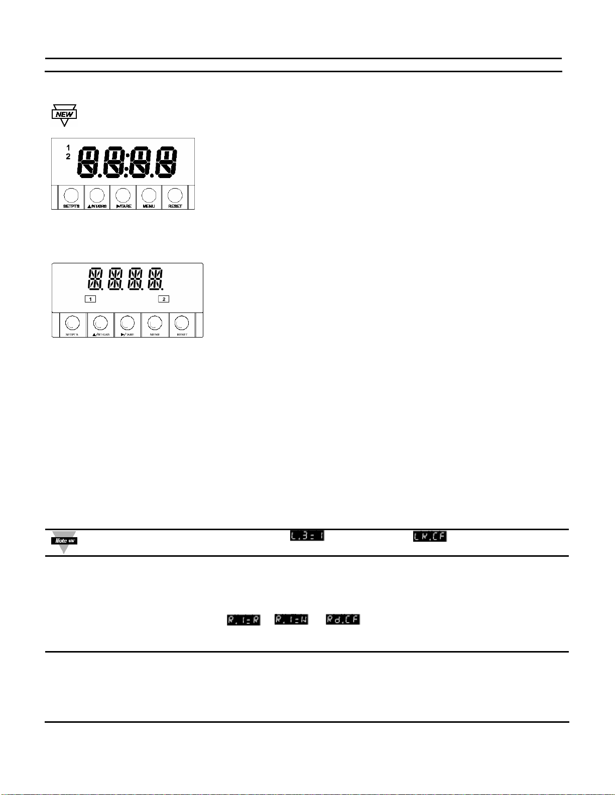
2.4 Front of the Meter
Figure 2-1 shows each part of the front of the three-color programmable “Big” LED display Meter (Version
B).
Digital LED Display:
-1.9.9.9 or 9.9.9.9 4-digit three color programmable, 21 mm (0.83”) high
LED display with programmable decimal point.
Figure 2-1 Front-Panel with Big Display
Figure 2-2 shows each part of the front of the standard LED display meter.
Digital LED Display:
-1.9.9.9 or 9.9.9.9 14 segment, 13.8 mm (0.54”)
high LED display with programmable decimal point.
Figure 2-2 Front-Panel with Standard Display
These meter display windows (both versions) light when appropriate:
1 Setpoint 1 status
2 Setpoint 2 status
5 Pushbuttons for programming the meter.
METER BUTTONS
SETPTS Button
In the Run Mode, this button will sequentially recall the previous setpoint settings. As necessary, use the
S/NT/GRS and X/TARE buttons to alter these settings, and then press the SETPTS button to store new values.
Unless you press the SETPTS, X/TARE, or SNT/GRS button within 20 seconds, the meter will scroll to setpoint 2
and then to the Run Mode.
If the dual relay option is not installed, or if
SETPTS button will display the meter’s firmware version.
S/NT/GRS Button
In the Run Mode, this button will toggle between net/gross readings or peak readings, depending upon setup.
In the Configuration Mode, press this button to change the value of the flashing digit shown on the display and/or
toggle between menu choices, such as
or on menu . When configuring your setpoint
values, press the S/NT/GRS button to advance the flashing digit’s value from 0 to 9 by 1.
X/TARE Button
In the Run Mode press the X/TARE button to tare your reading (zeroing).
In the Configuration Mode, press this button to scroll to the next digit.
is displayed on the menu, pressing the
DFI INFINITY CS (V- M3598/N/0906) 4 CF 70
Page 8
MENU Button
In the Run Mode, press the MENU button to terminate the current measuring strain and enter you into the
Configuration Mode.
Only if you have not installed the lock out jumpers on the main board.
In the Configuration Mode, press the MENU button to store changes in the nonvolatile memory and then advance
you to the next menu item.
RESET Button
If you hard reset (press the MENU button followed by the RESET button) or power off/on the meter, it shows
followed by
.
In the Run Mode, press the RESET button to reset the latched setpoints. The meter shows
and returns to
the Run Mode.
In the Configuration Mode, press the RESET button once to review the previous menu. Press the RESET button
twice to perform a hard reset and return to the Run Mode.
In the Peak Mode, press the RESET button to reset peak values. The meter shows and returns to the Run
Mode.
In the Setpoint Mode, press the RESET button to reset the latched setpoint. The meter shows
and enters
the Run Mode.
In the Tare Mode, press the RESET to reset. The meter shows
.
When in setpoint or Configuration Mode, if the meter shows 9999 or –1999 with all flashing digits, the
value has overflowed. Press the S/NT/GRS button to start a new value.
2.5 Back of the Meter
,
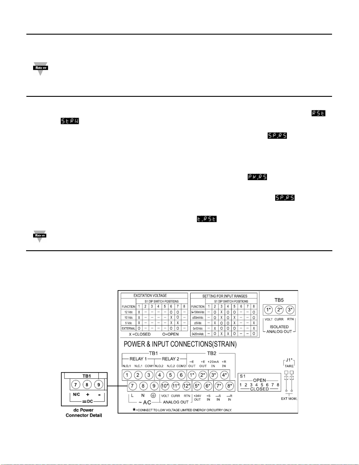
Figure 2-3 shows the label describing the connectors on the back of the meter. Table 2-2 on the following page
gives a brief description of each connector at the back of the meter.
Figure 2-3 Connectors (AC-Powered and DC-Powered Detail)
DFI INFINITY CS (V- M3598/N/0906) 5 CF 70
Page 9
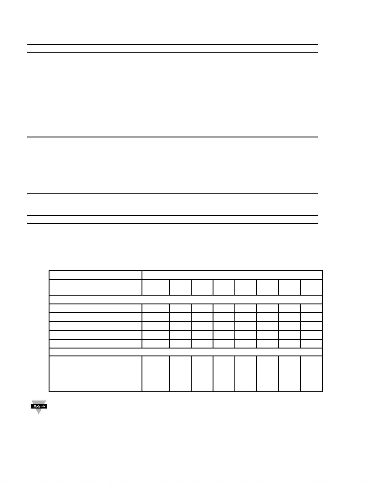
Table 2-2 Connector Description
Connector Description
TB1-1
TB1-2
TB1-3
TB1-4
TB1-5
TB1-6
TB1-7
TB1-8
TB1-9
TB1-10
TB1-11
TB1-12
TB2-1
TB2-2
TB2-3
TB2-4
TB2-5
TB2-6
TB2-7
TB2-8
TB5-1
TB5-2
TB5-3
J1 (1-2) Remote tare connection with a momentary switch
The DIP switches are located at the S1 position (Refer to Figure 3-2). Use a small instrument such as a paper clip
to change the switches from open to closed. Table 2-3 lists DIP switch settings at the S1 position required to
complete the setup of your meter.
Function
C= Closed
O= Open
Internal 5/10/12 excitation
External 5/10/12 excitation
Internal 12 Vdc Excitation
Internal 10 Vdc Excitation
Internal 5 Vdc Excitation
0-100 mV dc
±50 mV dc
±5 Vdc
0-10 Vdc
0-20 mA dc
Setpoint 1: Normally open (N.O.1) connection
Setpoint 1: Normally closed (N.C.1) connection
Setpoint 1: Common (COM1) connection
Setpoint 2: Normally open (N.O.2) connection
Setpoint 2: Normally closed (N.C.2) connection
Setpoint 2: Common (COM2) connection
AC line connection (no connections on DC-powered units)
AC neutral connection (+ Input on DC-powered units)
AC earth ground (DC-power return on DC-powered units)
Analog voltage output
Analog current output
Analog return
-E: Negative excitation connection from meter (5,10,12 V)
+E: Positive excitation connection from meter (5,10,12 V)
+20 mA connection for analog input
+R (Not used)
+24 V output connection
+S: Positive signal input
-S: Negative signal input and return for +20 mA or +24 V
-R (Not used)
Isolated Analog Voltage Output
Isolated Analog Current Output
Isolated Analog Output Return
Table 2-3 DIP Switch Positions/Input Range & Excitation
S1 DIP Switch Positions
1 2 3 4 5 6 7 8
Settings for Excitation Voltage
C - - - - - - O - - - - O O C - - - - O O C - - - - C O C - - - - C C -
Settings for Input Ranges
-
-
-
-
-
O
O
C
C
O
C
C
O
O
C
O
O
O
O
C
O
C
C
O
O
-
-
-
-
-
-
-
-
-
-
O
O
C
C
O
The display must also be configured to the selected input type after setting the DIP switches (see Section
4.1, Selecting the Input Type)
2.6 Disassembly
You may need to open up the meter for one of the following reasons:
DFI INFINITY CS (V- M3598/N/0906) 6 CF 70
Page 10
• To check or change the 115 or 230 Vac power jumpers.
• To install or remove jumpers on the main board.
Disconnect the power supply before proceeding.
To remove and access the main board, follow these steps:
• Disconnect main power from the meter.
• Remove the back case cover.
• Lift the back of the main board upwards and let it slide out of the case.
3.0 GETTING STARTED
Caution: The meter has no power-on switch, so it will be in operation as soon as you apply power.
If you power off/on the meter, or perform a hard reset (press the RESET button twice), the meter shows
followed by
.
3.1 Rating/Product Label
This label is located on top of the meter housing (refer to Figure 3-4).
3.2 Main Board Power Jumpers (Refer To Figure 3-1)
Important: If you want to change the Factory preset jumpers, do the following steps, otherwise go to
Section 3.3.
Warning: Disconnect the power from the unit before proceeding. This device must only be reconfigured
by a specially trained electrician with corresponding qualifications. Failure to follow all instructions and
warnings may result in injury!
1. Remove the main board from the case. Refer to Section 2.6.
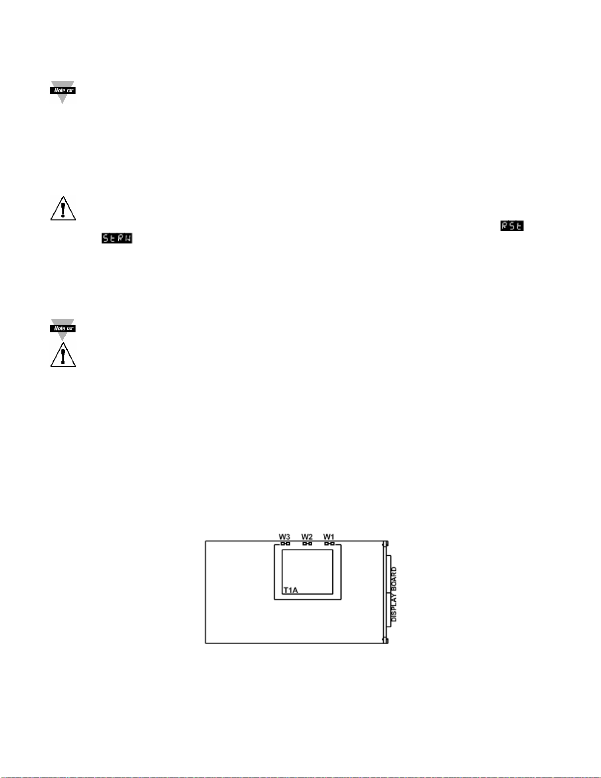
2. Locate the solder jumpers W1, W2, and W3 (located near the edge of the main board alongside the
transformer).
3. If your power requirement is 115 Vac, solder jumpers W1 and W3 should be wired, but jumper W2 should
not. If your power requirement is 230 V ac, solder jumper W2 should be wired, but jumpers W1 and W3
should not.
Note: W4 jumper is not used.
Figure 3-1 shows the location of solder jumpers W1 through W3.
Figure 3-1 Main Board Power Jumpers
Figure 3-2 shows the location jumper positions on the main board.
DFI INFINITY CS (V- M3598/N/0906) 7 CF 70
Page 11
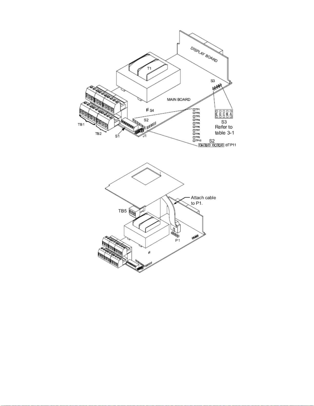
Figure 3-2 Main Board Jumper Positions
Figure 3-3 Upper Isolated Analog Output Option Board Installation
S2 jumpers are used for testing purposes. Do not use as reading errors may result.
S3 jumpers are used for the following (refer to Figure 3-2):
• To enable or disable the front panel push-buttons
• To allow for an extremely low resistance load button for analog output
• To disable the MENU button
• To perform factory calibration procedure
Test pins TP1 – TP11 are for testing purposes. Do not use as reading errors may result.
S4-A factory default jumper is removed.
DFI INFINITY CS (V- M3598/N/0906) 8 CF 70
Page 12

Jumper Description
S3-A
S3-B Removed. For factory calibration only.
S3-C Removed. Not Used
S3-D Installed for ex ternal ratiometric.
S3-E If installed without S3-B, the MENU button locks out. If you
3.3 Panel Mounting
Table 3-1 S3 Jumper Functions
Install to enable front panel push buttons.
Remove to disable all front panel push-buttons
press the MENU button, the meter shows
.
Figure 3-4 Meter – Exploded View
1. Cut a hole in your panel, as shown in Figure 3-4. For
specific dimensions refer to Figure 3-5.
2. Insert the meter into the hole. Be sure the front bezel
gasket is flush to the panel.
3. Slide on mounting bracket to secure.
4. Proceed to Section 3.4 to connect your sensor input
and main power.
NOTE: Dimensions in Millimeters (Inches)
Figure 3-5 Panel Cut Out
3.4 Connecting Sensor Inputs
Figure 3-6 shows excitation supplied from the meter’s internal supply (50mA maximum). Select 5,10, or 12 volt
excitation at DIP switch.
DFI INFINITY CS (V- M3598/N/0906) 9 CF 70
Page 13

Connections with ”typical wire colors”
+E = Positive Excitation (red)
-E = Negative Excitation (black)
+S = Positive Signal Input (green)
-S = Negative Signal Input (white)
Figure 3-6 Meter-powered Bridge Input
Figure 3-7 shows the connections required for an externally-powered bridge input: the external supply is brought to
the meter’s buffer circuits to permit ratiometric readings. Set S1 DIP switch for external excitation for Figure 3-7
and 3-8.
Connections with ”typical wire colors”
+E = Positive Excitation (red)
-E = Negative Excitation (black)
+S = Positive Signal Input (green)
-S = Negative Signal Input (white)
Figure 3-7 Externally-powered Bridge Input
Figure 3-8 4-Wire DC Input Connections with External Excitation
DFI INFINITY CS (V- M3598/N/0906) 10 CF 70
Page 14

Figure 3-9 Current Input Connections with Internal Excitation
Figure 3-10 Current Input Connections with External Excitation
3.5 Connecting Main Power
Connect the AC main power connections as shown in Figure 3-11.
WARNING: Do not connect AC power to your device until you have completed all input and output
connections. This device must only be installed by a specially trained electrician with correspondin g
qualifications. Failure to follow all instructions and warnings may result in injury!
Figure 3-11 Main Power Connections - AC
Table 3-2 shows the wire color and respective terminal connections for both USA and Europe.
DFI INFINITY CS (V- M3598/N/0906) 11 CF 70
Page 15

Table 3-2 AC-Power Connections
WIRE COLORS
TB1 AC POWER EUROPE USA
7
8
9
Connect the DC main power connections as shown in Figure 3-12.
When using DC power, refer to Table 8-1 Color Chart in the Specifications Section for Display Color,
Intensity, Excitation Voltage and Current, and Analog Output Isolated Option. Failure to use proper ratings
may result in damaging the unit.
AC Line
AC Neutral
AC Earth
Figure 3-12 Main Power Connections DC
Brown Black
Blue White
Green/Yellow Green
3.6 Connecting External Tare Switch
Connect external tare connections as shown in Figure 3-13.
Figure 3-13 External Tare Connections
3.7 Connecting Analog and Relay Outputs
If your have purchased a meter with analog or dual relay or isolated analog output, refer to the following drawings
for output connections.
DFI INFINITY CS (V- M3598/N/0906) 12 CF 70
Page 16

Figure 3-14 Analog Output Connections
Figure 3-15 Relay Output Connections
Figure 3-16 Isolated Analog Output Connections
DFI INFINITY CS (V- M3598/N/0906) 13 CF 70
Page 17

4.0 CONFIGURING THE METER
Refer to Table 6-1 for a summary list of menu configuration.
For first-time users: Refer to the QuickStart Manual for basic operation and set-up instruction s .
4.1 Selecting the Input Type
To select your appropriate input type signal, follow these steps:
Before proceeding, set the input DIP switch settings at the back of your meter. (Refer to
Table 2-3).
1. Press the MENU button. The meter shows
2. Press the X/TARE button. The meter flashes one of the following:
•
•
•
•
•
3. Press the S/NT/GRS button to scroll through available choices.
4. Press the MENU button to store your selection. The meter momentarily shows
(Decimal Point).
(for 0-100 mV dc) (Default)
(for ±50 mV dc)
(for 0-10 V dc)
(for ±5 V dc)
(for 0-20 mA dc).
4.2 Selecting a Decimal Point Position
.
, followed by
Refer to Table 6-1 for a summary list of menu configuration.
To select a decimal point display position, follow these steps:
1. Press the MENU button until the meter shows
2. Press the X/TARE button. The meter shows one of the following:
•
•
•
•
3. Press the S/NT/GRS button to scroll between available choices.
4. Press the MENU button to store your choice. The meter momentarily shows
(Reading Scale and Offset). Or you can press the RESET button to abort and go back to the
(Default)
, followed by
menu.
4.3 Using Reading Scale and Offset
Refer to Table 6-1 for a summary list of menu configuration.
To scale the meter to show readings in engineering units. There are two methods. One method is to scale with
known inputs. Another method is to scale without known inputs: you calculate input values based on the
transducer specifications and manually enter them through the keyboard.
4.3.1 Scaling with Known Loads (On-Line Calibration)
For maximum resolution, find the maximum signal that will be applied to the meter input.
• For regular voltage input, refer to the main body of Table 4-1.
• For millivolt or milliamp input, refer to the main body of Table 4-2.
Set the DIP switch positions as indicated at the top of either Table 4-1 or 4-2. The numbers 1 through 8 in the top
row of either table represent dip switches 1 through 8 and the O, C or X directly below the number indicates the
correct position of each switch.
• ‘O’ switch should be open or up.
DFI INFINITY CS (V- M3598/N/0906) 14 CF 70
Page 18

• ‘C’ switch should be closed or down.
• ‘X’ switch is used to control excitation (refer to Table 2-3 to determine correct position of these switches).
Once DIP switches have been positioned correctly, apply power. Proceed to the
(Reading Configuration)
and set R2 equal to the value in the right hand column of the chart.
Table 4-1 Range Selection DIP Switch Positions for Regular Voltage Input
12345678
XCOOOXXC
12345678
XCOOCXXC
RD.CF*
R2=
0 – 10 V ±5 V 4
0 – 5 V ±5 V 3
0 – 3 V ±3 V 2
0 – 2 V ±2 V 1
0 – 1 V ±1 V 0
Table 4-2 Range Selection DIP Switch Positions for Millivolt/Milliamp Input
12345678
XOCOOXX0
12345678
XOCOCXX0
12345678
XOCCOXX0
RD.CF*
R2=
0 – 100 mV ±50 mV 0 – 20 mA 4
0 – 50 mV ±50 mV 0 – 10 mA 3
0 – 30 mV ±30 mV 0 – 6 mA 2
0 – 20 mV ±20 mV 0 - 4 mA 1
0 – 10 mV ±10 mV 0 – 2 mA 0
* Reading Configuration
To scale with known inputs: apply known loads to a transducer connected to a meter, or simulate the transducer
output with a voltage or current simulator. To scale with known inputs, follow these steps:
1. Apply a known load equal to approximately 0% of the transducer range.
2. Press the MENU button until the meter shows
.
3. Press the X/TARE button. The meter shows (Input 1).
(Input 1) is the unscaled display reading at minimum input.
4. Press the X/TARE button again. The meter shows the last stored value for Input 1.
5. Press the X/TARE button once more. The meter shows the actual signal being received.
6. Press the MENU button to store this value as
(Input 1). The meter shows (Read 1).
(Read 1) is the desired display reading at Input 1.
7. Press the X/TARE button. The meter shows the last stored value for Read 1.
8. Press the S/NT/GRS button to change the value of your digits.
9. Press the X/TARE button to scroll horizontally to the next digit.
10. Press the MENU button to store this value as
(Input 2) is the unscaled display reading at maximum input.
. The meter shows (Input 2).
11. Apply a known load equal to approximately 100% of the transducer range.
12. Press the X/TARE button again. The meter shows the last stored value Input 2.
13. Press the X/TARE button once more. The meter shows the actual signal being received.
14. Press the MENU button to store Input 2 value. The meter shows
(Read 2).
(Read 2) is the desired display reading at Input 2.
15. Press the X/TARE button. The meter shows the last stored value for Read 2.
16. Press the S/NT/GRS button to change the value of your digits.
17. Press the X/TARE button to scroll horizontally to the next digit.
18. Press the MENU button to store this value as
by
. Meter scaling is now complete.
(Read 2). The meter momentarily shows , followed
DFI INFINITY CS (V- M3598/N/0906) 15 CF 70
Page 19

4.3.2 Scaling without Known Loads
To scale without known inputs, calculate input values based on transducer specifications and manually enter them
via the front-panel push buttons. The following example assumes load cells with these specifications:
Maximum Load: 100.0 lbs
Output: 3.1 mV/V
Sensor Excitation: 10 Vdc
Output: 31 mV = (3.1 mV/V) x (10 V)
1. Determine the correct values for
are equal to the minimum and maximum of the transducer output span. The example assumes &
are equal to the range of the load = 0 and = 100.0). Calculate and using the
load cell output span and the following equation:
= (Sensor Output) x (Natural Gain) x (Multiplier).
Input range Span units Natural gain
0 to 100 mV Millivolts 100 cts/mV
±50 mV Millivolts 40 cts/mV
0 to 10 V Volts 1000 cts/V
±5 V Volts 400 cts/V
0 to 20 mA Milliamps 500 cts/mA
2. Determine the multiplier by the Input Resolution setting (
Typically
3. Determine
4. Press MENU button until the meter shows
5. Press the X/TARE button. The meter shows
6. Press the X/TARE button again. The meter shows the last Input 1 value, with the fourth digit flashing.
7. Press the S/NT/GRS button to change the value of your digits.
8. Press the X/TARE button to scroll horizontally to the next digit.
9. Press the MENU button to store this value. The meter shows
10. Press the X/TARE button. The meter shows the last value for Read 1.
Repeat steps 7, 8 and 9 until
stored.
INPUT RANGE R.2 = 4 R.2 = 3 R.2 =2 R.2 = 1 R.2 =0
0 to 100 mV 1.000 2.000 3.333 5.000 10.00
0 to 10 V 1.000 2.000 3.333 5.000 10.00
0 to 20 mA 1.000 2.000 3.333 5.000 10.00
±50 mV 1.000 1.000 1.667 2.500 5.000
±5 V 1.000 1.000 1.667 2.500 5.000
resolution (
Example:
is suitable for most applications.
and input range and resolution. The example selects the 0 to 100 mV range and 10 uV
).
= (0 mV) x (100 cts/mV) x (1.000) =0
= (31 mV) x (100 cts/mV) x (1.000) = 3100
= 0000
= 100.0
, and have been displayed, verified, changed (if necessary) and
and , based on the load cell specifications. In most cases, &
Table 4-3 Natural Gain
in the menu) and the input range selected.
Table 4-4 Input Resolution Multiplier
.
.
.
4.4 Using Reading Configuration
Refer to Table 6-1 for a summary list of menu configuration.
DFI INFINITY CS (V- M3598/N/0906) 16 CF 70
Page 20

You may use Reading Configuration to configure your meter for the following:
• To select ratiometric or non-ratiometric operation
• To set the input resolution of your meter
• To display the filtered/unfiltered signal input value
• To select gross/net vs. peak reading
4.4.1 Selecting Ratiometric/Non-Ratiometric Operation
1. Press the MENU button until displays.
2. Press the X/TARE button. The meter flashes one of the following:
•
•
3. Press the S/NT/GRS button to view the last stored selection and to toggle between selections.
4. Press the X/TARE button to select input resolution or press the MENU button to store your selection and
shows
(Ratiometric reading) (Default – for strain meters)
(Non-ratiometric reading – typically for voltage & current transducers)
menu.
4.4.2 Setting Input Resolution
To set the input resolution of your meter, follow these steps:
1. Press the MENU button until
or
Press the X/TARE button from
One of the following displays (default is
= 10µV Unipolar inputs. 25 µV for bipolar inputs.
= 1µv for Unipolar inputs. 5 µV for bipolar inputs.
= 2µV for Unipolar inputs. 10 µV for bipolar inputs.
= 3µV for Unipolar inputs. 15 µV for bipolar inputs.
= 5µV for Unipolar inputs. 25µV for bipolar inputs.
Example: 3 µV resolution means that if you input 0-30 mV, at 30 mV the meter shows
2. Press the S/NT/GRS button to scroll through available selections.
3. Press the X/TARE button to display the filtered/unfiltered signal input or press the MENU button to store your
selection and shows
menu.
displays, then press the X/TARE button twice.
.
):
.
4.4.3 Displaying the Filtered/Unfiltered Input Signal
To display the filtered/unfiltered signal input, follow these steps:
1. Press the MENU button until
or
Press the X/TARE button from
One of the following displays:
•
•
2. Press the S/NT/GRS button to toggle between available choices.
3. Press the MENU button to store your selections.
= (Filtered value) (Default)
= Unfiltered value
displays, then press the X/TARE button three times.
.
momentarily displays, followed by Menu.
4.4.4 Selecting Gross/Net or Peak Display
To select gross/net or peak display.
1. Press the MENU button until
or
Press the X/TARE button from
One of the following displays:
•
•
2. Press the S/NT/GRS button to toggle between available choices.
3. Press the MENU button to store your selections.
= Gross/Net Display (Default)
= Peak Display
displays, then press the X/TARE button three times.
.
momentarily displays, followed by Menu.
DFI INFINITY CS (V- M3598/N/0906) 17 CF 70
Page 21

4.5 Selecting a Display Color
Refer to Table 6-1 for a summary list of menu configuration.
Selecting Display Color is not active unless your meter is a Version “B”.
To select a display color, follow these steps:
1. Press the MENU button until the meter shows
2. Press the X/TARE button. The meter shows one of the following:
•
•
•
3. Press the S/NT/GRS button to scroll between available choices.
Press the MENU button to store your choice. The meter momentarily shows
(Setpoint 1 Configuration). Or you can press the RESET button to abort and go back to the menu.
4.6 Using Setpoint 1 Configuration
Refer to Table 6-1 for a summary list of menu configuration.
Setpoint 1 Configuration
display whether the
• To set the setpoint’s active band above or below your chosen value
• To select whether the setpoint operation is latched or unlatched
• Assigning setpoint values to the net or gross reading
4.6.1 Setting Setpoint 1’s Active Band
1. Press the MENU button until the meter shows .
2. Press the X/TARE button. The meter shows one of the following:
•
•
3. Press the S/NT/GRS button to toggle between available choices.
4. Press the X/TARE button to select if Setpoint 1 is latched/unlatched or press the MENU button to store your
selection. The unit shows
= (Active above the setpoint) (Default)
= Active below the setpoint
4.6.2 Selecting if Setpoint 1 is Latched of Unlatched
1. Press the MENU button until displays, then press the X/TARE button twice.
or
Press the X/TARE button from
The meter shows one of the following:
•
•
2. Press the S/NT/GRS button to toggle between available choices.
3. Press the X/TARE button to assign Setpoint 1 values to net or gross reading or press the MENU button to
enter
= Setpoint 1 to be unlatched (Default)
= Setpoint 1 to be latched
(Setpoint 2 Configuration).
4.6.3 Assigning Setpoint 1 Values to Net or Gross Readings
1. Press the MENU button until displays, then press the X/TARE button twice.
or
Press the X/TARE button from
The meter shows one of the following:
is not active unless your meter has dual relay output capabilities. The LED’s will
is active or not. You may use Setpoint 1 Configuration for the following:
.
.
.
.
, followed by the next menu
DFI INFINITY CS (V- M3598/N/0906) 18 CF 70
Page 22

• = Setpoint 1 assigned to net reading (Default)
•
2. Press the S/NT/GRS button to toggle between available choices.
3. Press the MENU button to store your selection(s). The meter momentarily shows
(Setpoint 2 Configuration).
= Setpoint 1 assigned to gross reading
, followed by
4.7 Using Setpoint 2 Configuration
Refer to Table 6-1 for a summary list of menu configuration.
Setpoint 2 Configuration
display whether the
• To set setpoint’s active band above or below your chosen value
• To select whether the setpoint operation is latched or unlatched
• To assign setpoint values to the net or gross reading
is not active unless your meter has dual relay output capabilities. The LED’s will
is active or not. You may use Setpoint 2 Configuration for the following:
4.7.1 Setting Setpoints 2’s Active Band
1. Press the MENU button until the meter shows .
or
2. Press the X/TARE button. The meter shows one of the following:
•
•
3. Press the S/NT/GRS button to toggle between available choices.
4. Press the X/TARE button to select if Setpoint 2 is latched/unlatched or press the MENU button to store your
selection. The meter shows
= (Active above the setpoint) (Default)
= (Active below the setpoint)
.
4.7.2 Selecting if Setpoint 2 is Latched or Unlatched
1. Press the MENU button until displays, then press the X/TARE button twice.
or
Press the X/TARE button from
The meter shows one of the following:
•
•
2. Press the S/NT/GRS button to toggle between available choices.
3. Press the MENU button to store your selection(s). The meter momentarily shows
(Setpoint 1 Deadband).
= Setpoint 2 to be unlatched (Default)
= Setpoint 2 to be latched
.
, followed by
4.7.3 Assigning Setpoint 2 Values to Net or Gross Readings
1. Press the MENU button until displays, then press the X/TARE button twice.
or
Press the X/TARE button from
The meter will show one of the following:
•
•
2. Press the S/NT/GRS button to toggle between available choices.
3. Press the MENU button to store your selection(s). The meter momentarily shows
(Setpoint 1 Deadband).
= Setpoint 2 assigned to net reading (Default)
= Setpoint 2 assigned to gross reading
.
, followed by
4.8 Setting the Setpoint 1 Deadband
Refer to Table 6-1 for a summary list of menu configuration.
Setpoint 1 Deadband
display whether the
(hysteresis) of Setpoint 1, follow these steps:
DFI INFINITY CS (V- M3598/N/0906) 19 CF 70
is not active unless your meter has dual relay output capabilities. The LED’s will
is active or not. The Setpoint 1 Default deadband is 0003. To change the deadband
Page 23

1. Press the MENU button until the meter shows .
2. Press the X/TARE button. The meter shows the last previously stored 4-digit number (0000 through 9999)
with flashing 4
th
digit.
3. Press the S/NT/GRS button to change the value of the flashing digit. If you continue to press the S/NT/GRS
button, the flashing digit’s value continues to change.
4. Press the X/TARE button to scroll to the next digit.
5. Press the MENU button to store the selection. The meter momentarily shows
, followed by
(Setpoint 2 Deadband).
4.9 Setting the Setpoint 2 Deadband
Refer to Table 6-1 for a summary list of menu configuration.
Setpoint 2 Deadband
display whether the
(hysteresis) of Setpoint 2, follow these steps:
1. Press the MENU button until the meter shows
2. Press the X/TARE button. The meter shows the last previously stored 4-digit number (0000 through 9999)
with flashing 4
th
digit.
3. Press the S/NT/GRS button to change the value of the flashing digit. If you continue to press the S/NT/GRS
button, the flashing digit’s value continues to change.
4. Press the X/TARE button to scroll to the next digit.
5. Press the MENU button to store your selection. The meter momentarily shows
(Output Configuration) if you have analog output capabilities.
is not active unless your meter has dual relay output capabilities. The LED’s will
is active or not. The Setpoint 2 default deadband is 0003. To change the deadband
.
, followed by
Figure 4-1 Alarm Example
DFI INFINITY CS (V- M3598/N/0906) 20 CF 70
Page 24

To reset latched alarms you must:
1. Input a signal OUT of the alarm zone
2. Then press SETPTS and then, RESET button
4.10 Using Output Configuration
Refer to Table 6-1 for a summary list of menu configuration.
Output Configuration
whether analog output is present or not. Analog output must be ordered at time of purchase.
Use Output Configuration
• To enable or disable the analog output
• To select if the analog output is current or voltage
• To assign the output to the net or gross reading
is not active unless your meter has analog output capabilities. The menu will display
to select the following:
4.10.1 Enabling or Disabling the Analog Output
To enable or disable the analog output, follow these steps:
1. Press the MENU button until the meter shows
2. Press the X/TARE button. The meter shows one of the following:
•
•
3. Press the S/NT/GRS button to toggle between available choices.
4. Press the X/TARE button to select analog output as current or voltage or press the MENU button to store your
selection and enter
= (Analog output enabled) (Default))
= (Analog output disabled)
(Output Scale and Offset).
.
4.10.2 Selecting Analog Output as Current or Voltage
1. Press the MENU button until it shows , and then press the X/TARE button twice.
or
Press the X/TARE button from
The meter will show one of the following:
•
•
2. Press the S/NT/GRS button to toggle between available choices.
3. Press the X/TARE button to select analog output or proportional control or press the MENU button to store
your selection and enter
= (Analog output=current) (Default)
= (Analog output=voltage)
.
(Output scale and Offset).
4.10.3 Selecting Analog Output or Proportional Control
1. Press the MENU button until it shows , and then press the X/TARE button twice.
or
Press the X/TARE button from
The meter shows one of the following:
•
•
2. Press the S/NT/GRS button to toggle between available choices.
3. Press the MENU button to store your selection. The meter momentarily shows:
(Output Scale and Offset).
= (Net Reading) (Default)
= (Gross Reading)
.
, followed by
4.11 Using Output Scale and Offset
Refer to Table 6-1 for a summary list of menu configuration.
Output Scale and Offset
display whether analog output is present or not. Output Scale and Offset
DFI INFINITY CS (V- M3598/N/0906) 21 CF 70
is not active unless your meter has analog output capabilities. The menu will
scales your analog output to be
Page 25

equal to the meter’s display and/or any engineering units you require. You may scale the output for direct (4-20
mA, 0-10 V, etc) or reverse acting (20-4 mA, 10-0 V, etc).
1. Press the MENU button until
2. Press the X/TARE button.
displays.
(Read 1) displays.
This is your first point of display reading.
3. Press the X/TARE button again. The meter shows the last previously stored 4-digit number (-1999 through
9999) with flashing 4
th
digit.
4. Press the S/NT/GRS button to change the digits.
5. Press the X/TARE button to scroll to the next digit.
6. Press the MENU button to store your selection.
(Output 1) displays.
This starting analog signal corresponds to your Read 1 display.
7. Press the X/TARE button. Selected output displays.
If you select
signal output. If you select
for voltage, the maximum signal you may select is 10.00 for a 0-10 Vdc
for current, the maximum signal you may select is 20.00.
8. Press the S/NT/GRS button to enter the Output 1 signal selection. If you continue to press the S/NT/GRS
button, the flashing digit’s value continues to change.
9. Press the X/TARE button to scroll horizontally to the next digit.
10. Press the MENU button to store your selection.
(Read 2) displays.
This is your second point of display reading.
11. Press the X/TARE button. The meter shows the last previously stored 4-digit number (-1999 from 9999) with
flashing 4
th
digit.
12. Press the S/NT/GRS button to change the value of the flashing digit. If you continue to press the S/NT/GRS
button, the flashing digit’s value continues to change.
13. Press the X/TARE button to scroll horizontally to the next digit.
14. Press the MENU button to store your selection. The meter shows
(Output 2).
This analog signal should correspond to your Read 2 display.
15. Press the X/TARE button. The meter shows the selected output.
If you select
If you select
for voltage, the maximum signal you may select is 10.00 for a 0-10 V signal output.
for current, the maximum signal you may select is 20.00 for a 0-20 or 4-20 mA DC
signal output.
16. Press the S/NT/GRS button to change the value of the flashing digit. If you continue to press the S/NT/GRS
button, the flashing digit’s value continues to change.
17. Press the X/TARE button to scroll horizontally to the next digit.
18. Press the MENU button to store your selection. The meter momentarily shows , followed by
(Lock Out configuration).
WARNING: If the meter shows flashing values on any time, the value has overflowed. Press the
S/NT/GRS button to start new values.
4.11.1 Examples for Output Scale and Offset
Example: You want to spend 4-20 mA output for 0 to 100.0. The meter has 0.1 degrees resolution. Complete the
following steps:
1. Press the MENU button until the meter shows
2. Press the X/TARE button. The meter shows
3. Press the X/TARE button to show the existing value.
4. Change the value of Read 1 to 000.0 by pressing the S/NT/GRS and X/TARE buttons.
5. Press the MENU button to store your selection. The meter shows
6. Press the X/TARE button to show the existing value.
7. Change the value of Output 1 to 04.00 by pressing the S/NT/GRS and X/TARE buttons.
8. Press the MENU button to store your selection. The meter shows
.
(Read 1).
(Output 1).
(Read 2).
DFI INFINITY CS (V- M3598/N/0906) 22 CF 70
Page 26

9. Press the X/TARE button to show the existing value.
10. Change the value of Read 2 to 100.0 by pressing the S/NT/GRS and X/TARE buttons.
11. Press the MENU button to store your selection. The meter shows
12. Press the X/TARE button to show the existing value.
13. Change the value of Output 2 to 20.0 by pressing the S/NT/GRS and X/TARE buttons.
14. Press the MENU button to store your selection. The meter shows
(Output 2).
(Lock Out Configuration).
4.12 Using Lock Out Configuration
Refer to Table 6-1 for a summary list of menu configuration.
Use Lock Out Configuration
• To enable or disable setpoint changes
• To enable or disable the RESET button in the Run Mode
• To enable or disable displaying meter firmware version
for the following:
4.12.1 Enabling or Disabling the RESET button in the Run Mode
1. Press the MENU button until the meter shows (after .)
2. Press the X/TARE button. The meter shows one of the following:
•
•
3. Press the S/NT/GRS button to toggle between available choices.
4. Press the MENU button to store the changes. The meter shows
the meter shows
= To enable the RESET button in the Run mode (Default)
= To disable the RESET button in the Run mode
if the new value is different otherwise
and returns to the Run mode.
4.12.2 Enabling or Disabling the SETPOINT Changes
1. Press the MENU button until the meter shows (after )
2. Press the X/TARE button twice. The meter shows one of the following:
•
•
3. Press the S/NT/GRS button to toggle between available choices.
4. Press the MENU button to store the changes. The meter shows
the meter shows
= To enable the setpoint changes (Default)
= To disable the setpoint changes
if the new value is different otherwise
and returns to the Run Mode.
4.12.3 SETPOINT Display Function: Firmware version or Setpoint value
1. Press the MENU button until the meter shows (after )
2. Press the X/TARE button three times. The meter shows one of the following:
•
•
3. Press the S/NT/GRS button to toggle between the choices above.
4. Press the MENU button to store the changes. The meter shows
the meter shows
= SETPTS button will display setpoint values.
= SETPTS button will display the meter’s firmware version.
if the new value is different otherwise
and returns to the Run Mode.
If your meter does not have the relay option, setpoint menu items above will not be available and SETPTS
button will always display the meter’s firmware version. These units will have
memory indicated by Alarm 1 & 2 LED displays. LEDs can be reset by pressing MENU then RESET
button or by Power OFF then ON.
4.13 Using Display Brightness Configuration
(overload) or
4.13.1 Changing Brightness Level
Changing Display Brightness is not active unless your meter is a Version “B”.
1. Press the MENU button the meter shows
2. Press the X/TARE button from
DFI INFINITY CS (V- M3598/N/0906) 23 CF 70
. The meter shows one of the following:
(after ).
Page 27

• = Medium Brightness
•
•
3. Press the S/NT/GRS button to toggle between available choices.
4. Press the MENU button to store your selection. The meter momentarily shows
= Low Brightness
= High Brightness(Default)
, , and then measured value.
5.0 DISPLAY MESSAGES
Table 5-1 Display Messages
MESSAGE DESCRIPTION
Strain Meter
Hard (Power On) Reset
Input Type
Decimal Point Position
Reading Scale and Offset
Reading Configuration
Display Color
Setpoint 1 Configuration
Setpoint 2 Configuration
Setpoint 1 Deadband
Setpoint 2 Deadband
Output configuration
Output Scale and Offset
Lock Out configuration
Display Brightness
+Overload Signal
- Overload Signal
Resolution Overflow
Value Overflow in Setpoint/Menu Routines
Value Overflow in Setpoint/Menu Routines
Net Value Overflow
Gross Value Overflow
2 Coordinate Format Programming Error
Peak Value
Peak Reset
Tare Reset
Setpoint Reset
Net Value
Gross Value
Setpoint 1 Value
Setpoint 2 Value
Resolution Over Scale
Firmware Version (where 8 is 0 ~ 9)
Operating Mode
followed by ,
DFI INFINITY CS (V- M3598/N/0906) 24 CF 70
Page 28

6.0 MENU CONFIGURATION DISPLAYS
Not all items display on standard meters.
Table 6-1 Menu Configuration Displays
(Defaults in Bold and Italics)
MENU X/TARE S/NT/GRS
Show input choices:
Show current decimal point position
(Reading Scale &
Offset)
Enter new value
2
and show
Enter new value
4
and show
Enter new value
6
and show
Show
1
Shows prior value entered and flashing
digit. Scrolls to the next digit
• If X/TARE is pressed, actual input is
shown and cannot be changed with
S/NT/GRS.
• If S/NT/GRS is pressed, unit can
scroll through digits with X/TARE.
Shows prior value entered and flashing
3
digit. Scrolls to the next digit.
Shows prior value entered and flashing
5
digit. Scrolls to the next digit.
• If X/TARE is pressed, actual input is
shown and cannot be changed with
S/NT/GRS.
• If S/NT/GRS is pressed, unit can
scroll through digits with X/TARE.
Shows prior value entered and flashing
7
digit. Scrolls to the next digit.
(Default)
(Default)
Changes the value of the flashing
digit.
Changes the value of the flashing
digit.
Changes the value of the flashing
digit.
Changes the value of the flashing
digit.
DFI INFINITY CS (V- M3598/N/0906) 25 CF 70
Page 29

MENU X/TARE S/NT/GRS
Reading Configuration
Display Color Selection
Setpoint 1 Configuration
R.1=
R.2=
R.3=
R.4=
Show input choices:
S.1=
(Ratiometric Reading)
(Non-ratiometric reading)
(1µV resolution for unipolar & 5µV
resolution for bipolar)
(2µ V resolution for unipolar & 10µV
resolution for bipolar)
(3µ V resolution for unipolar & 15µV
resolution for bipolar)
(5µ V resolution for unipolar & 25µV
resolution for bipolar)
(10µ V resolution for unipolar & 25µV
resolution for bipolar)
Note: 3 µV resolution means if your input is 0-30mV,
at 30mV the display shows 9999.
(Filtered value)
(Unfiltered value)
(Gross/Net Display)
(Peak Display)
Green
Red
Amber
(Active above)
(Active below)
Setpoint 2 Configuration
Setpoint 1 Deadband
Setpoint 2 Deadband
S.2=
S.3=
S.1=
S.2=
S.3=
Press to scroll to the next
digit to the right.
Press to scroll to the next
digit to the right
(Unlatched)
(Latched)
(Net Reading)
(Gross Reading)
(Active above)
(Active below)
(Unlatched)
(Latched)
(Net Reading)
(Gross Reading)
Press to change the value of the flashing digit.
Press to change the value of the flashing digit
DFI INFINITY CS (V- M3598/N/0906) 26 CF 70
Page 30

MENU X/TARE S/NT/GRS
Output Configuration
0.1 =
0.2 =
(Analog output is enabled)
(Analog output is disabled)
(Analog output is current)
(Analog output is voltage)
Output Scale & Offset
(Shown if
Configuration Menu
Enter new value and
2
show
Enter new value and
4
show
Enter new value and
6
show
Lock Out Configuration
in Output
.
.
.
0.3 =
Show
1
)
Shows prior value
entered and flashing digit.
Scrolls to the next digit
Shows prior value
3
entered and flashing digit.
Scrolls to the next digit.
Shows prior value
5
entered and flashing digit.
Scrolls to the next digit.
Shows prior value
7
entered and flashing digit.
Scrolls to the next digit.
RS =
Changes the value of the flashing digit.
Changes the value of the flashing digit.
Changes the value of the flashing digit.
Changes the value of the flashing digit.
(Net Reading)
(Gross Reading)
(Enable RESET button in the Run Mode)
(Disable RESET button in the Run Mode)
Brightness Configuration
DFI INFINITY CS (V- M3598/N/0906) 27 CF 70
Shows input choices:
SP =
L3 =
(Enable setpoint changes)
(Disable setpoint changes)
(SETPTS button display setpoint values)
(SETPTS button display firmware version
(Medium Brightness)
(Low Brightness)
(High Brightness)
where 8 is 0 ~ 9)
Page 31

Table 6-2 Run Mode Displays
Display X/TARE S/NT/GRS RESET Description
/
Displays NET or GROSS
Press to
activate
reading. Once reading shows,
respective value shows.
Will reset your
tare when
viewing this
function
Peak Reading
Toggle between Net and Gross
values.
Tare Reset
Reset Latched Alarms
Pressing the RESET button
resets your latched alarm
7.0 SETPOINT CONFIGURATION DISPLAYS
Table 7-1 Setpoint Configuration Displays
MENU X/TARE S/NT/GRS Description
Press to scroll to the
next digit to the right
Press to scroll to the
next digit to the right
Press to change the
value of the flashing
digit
Press to change the
value of the flashing
digit
SETPOINT 1
Select from –1999 through 9999
SETPOINT 2
Select from –1999 through 9999
8.0 SPECIFICATIONS
SIGNAL INPUT
Input Ranges: 0-100mV, ± 50 mV, 0-10 V, ± 5 V, 0-20 mA, 4-20 mA
Isolation: Dielectric strength to 2500V transient per 3mm spacing based on EN 61010 for
260Vrms of DC working Voltage
Noise Rejection: Normal Mode Rejection (NMR) = 60dB
Common Mode Rejection (CMR) = 120dB
Resistance: 100 Meg ohms for 100 mV or ±50 mV input range
1 Meg ohm for 10 or +5 V input range
5 ohms for 20 mA current input range
Big Display
Symbol:
Standard Display: 4-digit, 14-segment LED, 13.8 mm (0.54”)
Symbol:
: 4-digit, three color programmable 9-segment, LED 21 mm (0.83”)
(-1.9.9.9 ~ 9.9.9.9)
(-1.9.9.9 ~ 9.9.9.9.)
ANALOG TO DIGITAL
Technique: Dual slope
Internal resolution: 15 bits
Read Rate: 3/sec Polarity Automatic
DFI INFINITY CS (V- M3598/N/0906) 28 CF 70
Page 32

ACCURACY AT 25oC
Max Error Strain: ±0.03% of reading, ± 1 count
Span Tempco: 50 ppm/°C
Step Response: 1 sec
Warm Up to Rated Accuracy: 30 min
Excitation Voltage: AC power units
24 V @ 25 mA, Refer to Table 8-1
12 V @ 50 mA, Color chart for DC Output
10 V @ 120 mA, Excitation
5 V @ 60 mA
Load Regulation: 1.1%
Line Regulation: 0.02% per Vac
DC power units
ALARM OUTPUTS (if applicable)
2 Form “C” on/off relays. Configurable for latched and unlatched by software.
Max current: 5 AMPS, resistive load
Max voltage: 250 Vac or 30 Vdc
ANALOG OUTPUT (if applicable)
Signal Type: Current or voltage
Signal Level: Current: 10 V max compliance at 20 mA output
Voltage: 20 mA max for 0-10 V output
Function: May be assigned to a display range or proportional control output with setpoint #1
when used as a control output.
Linearity: 0.2%
Step Response Time: 2 – 3 seconds to 99% of the final value
ISOLATED ANALOG OUTPUT (TB5, if applicable)
Same as non-isolated analog output except isolated.
Signal Type: Current or voltage
Signal Level: Current: 10 V max compliance at 20 mA output
Voltage: 20 mA max for 0-10 V output
Function: May be assigned to a display range or proportional control output with Setpoint #1
when used as a control output.
Linearity: 0.2%
Step Response Time: 2 – 3 seconds to 99% of the final value
Isolation: 130 Vrms working voltage, 1000 V/60sec Dielectric test
Only one analog output is available on each unit and it must be factory installed.
INPUT POWER INFORMATION
AC units 115/230 V~(AC) ±10%, 50/60 Hz
9.5 W max, power consumption (Non-Isolated Analog Out)
11.0 W max, power consumption (Isolated Analog Out)
DC Units 10-32 Vdc or 26-56 Vdc, 8 W
Do not use a combination of dc power and internal excitation or Isolated Analog
Out, unless using dc power of 20-32 Vdc.
Refer to Table 8-1 below
External Fuse Required:
DFI INFINITY CS (V- M3598/N/0906) 29 CF 70
IEC 127-2/111
Power Fuse
115V 125 mA @ 250 (T)
230V 63 mA @ 260 (T)
UL 248-14 (Listed Fuse)
Power Fuse
115V 175 mA @ 250 V Slow-Blo w
230V 80 mA @ 250 Slow-Blo w
Page 33

ENVIRONMENT
Operating Temperature: 0° to 50°C (32° to 122°F)
Storage Temperature: -40° to 85°C (-40° to 185° F)
Relative humidity: 90% at 40°C (non-condensing)
MECHANICAL
Panel cutout: 1/8” DIN 3.62 x 1.78” (45 x 92mm)
Weight: 1.27 lb (575 g)
Case material: Polycarbonate, 94 V-O UL rated
Protection: NEMA-4/Type 4 Front Bezel
Table 8-1 Color Chart for DC Power
COLOR HIGH BRIGHTNESS MEDIUM & LOW BRIGHTNESS
Sensor Excitation:
24 V @ 25 mA,
RED
GREEN
AMBER
12 V, 10 V, 5 V @ 35 mA Max
Analog Output:
Non-Isolated option only
Warning:
• Do not use Internal Excitation.
Use External Excitation.
• Do not use Isolated Analog Output.
Use Non-Isolated Analog Output.
Any combination of Sensor
Excitation and Analog Output
24 V @ 25 mA,
12 V @ 35 mA Max
10 V @ 35 mA Max
5 V @ 35 mA Max
Analog Output:
Non-Isolated options or
Isolated Analog option
HIGH/LOW Brightness and AMBER are only available on Version “B” meters. Standard display meters are
MEDIUM Brightness.
Figure 8-1 Meter Dimensions/Panel Cutout
DFI INFINITY CS (V- M3598/N/0906) 30 CF 70
Page 34

9.0 FACTORY PRESET VALUES
Table 9-1 Factory Preset Values
MENU ITEM FACTORY PRESET VALUES
Sensor Excitation: 10Vdc
Input Type: 0-100 (0-100 mV input)
Decimal Point Position:
Reading Scale and Offset:
0-100 mV = 0-1000
Reading Configuration:
(Ratiometric)
(10µV resolution for unipolar & 25 µV resolution for
bipolar)
(Filtered value)
(Gross/net reading)
Normal Color Display:
or (Note: depending how unit was ordered)
Setpoint 1 Configuration:
(Setpoint is active above)
(Setpoint is unlatched)
(Net Reading)
Setpoint 2 Configuration:
(Setpoint is active above)
(Setpoint is unlatched)
(Net Reading)
Setpoint 1 Deadband:
Setpoint 2 Deadband:
Output Configuration:
(Analog output is enabled)
(Analog output is current)
(Analog output follows the Net value)
Output Scale and Offset:
0-1000 = 4-20 mA DC
Lock Out Configuration
(Enable the RESET button in the Run Mode)
(Enable setpoint changes)
(Display setpoint values)
(Brightness Level)
Setpoint 1 Value:
Setpoint 2 Value:
10.0 CE APPROVALS INFORMATION
This product conforms to the EMC directive 89/336/EEC amended by 93/68/EEC, and with the European Low
Voltage Directive 72/23/EEC.
Electrical Safety EN61010-1:2001
Safety requirements for electrical equipment for measurement, control and laboratory.
Double Insulation
Pollution Degree 2
Dielectric withstand Test per 1 min
DFI INFINITY CS (V- M3598/N/0906) 31 CF 70
Page 35

• Power to Input/Output: 2300 Vac (3250 Vdc)
• Power to Input/Output: 500 Vac (720 Vdc)
(Low Voltage dc Power Option*)
• Power to Relays Output: 2300 Vac (3250 Vdc)
• Relay 1 to Relay 2: 2300 Vac (3250 Vdc)
• Isolated Analog to Inputs: 1000 Vac (1420 Vdc)
• Analog to Inputs: No Isolation
Measurement Category I
Category I are measurements performed on circuits not directly connected to the Mains Supply (power). Maximum
Line-to-Neutral working voltage is 50 Vac/dc. This unit should not be used in Measurement Categories II, III, IV.
Transients Overvoltage Surge (1.2 / 50uS pulse)
• Input Power: 2500 V
• Input Power: 500 V
(Low Voltage dc Power Option*)
• Isolated Analog: 500 V
• Input/Output Signals: 500 V
Note: *Units configured for external low power dc voltage, 10-32 Vdc (Basic Insulation)
EMC EN61326:1997 + and A1:1998 + A2:2001
Immunity and Emissions requirements for electrical equipment for measurement, control and laboratory.
• EMC Emissions Table 4, Class B of EN61326
• EMC Immunity** Table 1 of EN61326
Note: **I/O signal and control lines require shielded cables and these cables must be located on conductive cable
trays or in conduits. Furthermore, the length of these cables should not exceed 3 0 meters
Refer to the EMC and Safety installation considerations (Guidelines) of this manual for additional
information.
WARRANTY REPAIR POLICY
Limited Warranty On Products
Any Cooper Instruments product which, under normal operating conditions, proves defective in material or in
workmanship within one year of the date of shipment by Cooper will be repaired or replaced free of charge provided
that a return material authorization is obtained from Cooper and the defective product is sent, transportation
charges prepaid, with notice of the defect, and it is established that the product has been properly installed,
maintained, and operated within the limits of rated and normal usage. Replacement or repaired product will be
shipped F.O.B. from our plant. The terms of this warranty do not extend to any product or part thereof which, under
normal usage, has an inherently shorter useful life than one year. The replacement warranty detailed here is the
buyer’s exclusive remedy, and will satisfy all obligations of Cooper whether based on contract, negligence, or
otherwise. Cooper is not responsible for any incidental or consequential loss or damage which might result from a
failure of any and all other warranties, express or implied, including implied warranty of merchantability or fitness for
particular purpose. Any unauthorized disassembly or attempt to repair voids this warranty.
Obtaining Service Under Warranty
Advance authorization is required prior to the return to Cooper Instruments. Before returning the item, contact the
Repair Department c/o Cooper Instruments at (540) 349-4746 for a Return Material Authorization number.
Shipment to Cooper shall be at buyer’s expense and repaired or replacement items will be shipped F.O.B. from our
plant in Warrenton, Virginia. Non-verified problems or defects may be subject to a $150 evaluation charge. Please
return the original calibration data with the unit.
Repair Warranty
All repairs of Cooper products are warranted for a period of 90 days from date of shipment. This warranty applies
only to those items that were found defective and repaired; it does not apply to products in which no defect was
found and returned as is or merely recalibrated. It may be possible for out-of-warranty products to be returned to
the exact original specifications or dimensions.
DFI INFINITY CS (V- M3598/N/0906) 32 CF 70
Page 36

* Technical description of the defect: In order to properly repair a product, it is absolutely necessary for Cooper to
receive information specifying the reason the product is being returned. Specific test data, written observations on
the failure and the specific corrective action you require are needed.
DFI INFINITY CS (V- M3598/N/0906) 33 CF 70
 Loading...