

Page 1

DFI 7000 DIGITAL FORCE INDICATOR USER’S GUIDE
1.0 INTRODUCTION
The DFI 7000 Signal Conditioner-Indicator is a complete 4-1/2-digit signal conditioner and indicator housed in a 1/8
DIN case. This unit provides many of the features found on expensive, larger signal conditioning units.
• Full 20,000 count resolution
• Accepts strain-gage transducer inputs from 0.5 to 50 mv/v
• 0-5V output
• +/-0.03% accuracy
• Screw-type power and I/O connectors
• Shunt calibration from front-panel
• 1/8 DIN “panel meter size” case
• 5- or 10-volt transducer excitation
• Optional Dual Limits
• Optional Peak Detector
• Optional Track-and-Hold
• 110- or 220-V Power
2.0 DESCRIPTION
2.1 Configuration
Within the DFI 7000’s enclosure there are three printed circuit boards (four if an option is selected). The Main
Board contains the circuitry for the power supply and A/D converter. The Display Board contains all circuitry
needed to drive the LED display and the units display bar. The Signal Conditioner Board contains circuitry for the
signal amplifier and for the excitation power supply.
The Display Board solders to the main Board, whereas the Signal Conditioner plugs into it. If the Dual Limits, Peak
Detector or Track-and-Hold option is supplied, a fourth plug-in board houses it. DUE TO SPACE CONSTRAINTS,
ONLY ONE OPTION CAN BE INSTALLED ON A PARTICULAR UNIT. Adjustments for COARSE SPAN, COARSE
ZERO, FINE ZERO, and SCALING are provided. FINE ZERO and FINE SPAN may be adjusted from the front
panel without removing the front bezel. The entire unit may be quickly panel- or rack-mounted with the snap-on
attachments supplied with every unit.
2.2 Specifications
GENERAL
# Channels 1
Case Material Noryl Plastic
Temperature Storage
Temperature Operating
TRANSDUCER INTERFACE
Transducer Excitation 5 or 10 VDC
Type of inputs accepted 0.5 mv/v to 5.0 mv/v or 5 mv/v to 50 mv/v
Transducer Current drive (ma.) 50
Input Gain Range 10-1000
Push Button Shunt Cal Yes
Calibration Method Manual (front panel)
Zero Balance +/- 15% F.S. Min.
Noise & Ripple <100 microvolts
Transducer Minimum Impedance 350Ω (10v Exc.)
CF11 1 V-May 2003-008-0186-00
-20° F to 200° F
32° F to 130° F
Page 2

AMPLIFIER CHARACTERISTICS
Full-Scale Output 5 Volts
Output Impedance <2 ohms
Accuracy +/-0.03%
Frequency Response >100 Hz.
Common Mode Rejection >80%
Fine Span Adjust +/-15%
Coarse Zero Adjust >80%
Short Circuit Protected Yes
DIGITAL DISPLAY CHARACTERISTICS
# Characters Displayed 4-1/2
Conversions per second 3
Scaling 0-19999
Scaling Method Potentiometer
Polarity Indication "-" for Negative
Decimal Pt. Selection Jumper (non-solder)
Display Size 0.56”
Overrange Indication Flashing display
Resolution 1/20000
Type LED
PHYSICAL CHARACTERISTICS
Input/Output Connector Screw Terminals
Weight 2 lbs.
Mounting Bench, panel or rack
DIN Size 1/8 DIN
POWER SUPPLY
Power Requirements 115VAC/220VAC (factory set, field changeable)
FRONT PANEL
Digital Display 4-1/2 digits LED
Limit Condition LEDs
3.0 UNPACKING, INSTALLING AND WIRING
The DFI 7000 is shipped in a single container. Inspect the unit for shipping damage, and gently shake and listen
for loose components prior to energizing it. Report shipment damage to the carrier; it is his responsibility to safely
transport the unit. If there is transportation damage and you have difficulty getting the problem resolved, contact
Cooper at (540) 349-4746. We will attempt to assist in resolving the situation.
3.1 Selecting Excitation Voltage
The DFI 7000 provides a 5 or 10 VDC strain-gage transducer power supply. These units are normally set for 10
VDC at the factory. To check or change the excitation voltage, proceed as follows:
1. Remove the bezel and front panel with a small screwdriver.
2. Carefully pull the Main Board out of the unit. All boards will come out simultaneously.
3. Gently remove the vertical Signal Conditioner Board from the right edge of the Main Board and locate the two
sets of three standoffs at the left end of this board. Check the jumper location for excitation voltage setup.
5 Volt Excitation10 Volt Excitation
4. Replace the Signal Conditioner Board onto the Main Board and slide the board assembly into the case.
5. Reinstall the front panel and bezel.
CF11 2 V-May 2003-008-0186-00
Page 3
3.2 Mounting the Unit
For panel mounting, cut a rectangular hole 3.58” in width by 1.73” in height. Remove the panel mounting brackets
by unsnapping them from the sides of the DFI 7000. Place the DFI 7000 through the panel cutout and reattach the
panel mounting brackets to the sides of the case. Use a small screwdriver to tighten the panel mounting bracket
adjusting screws until the case is pulled tightly into the panel.
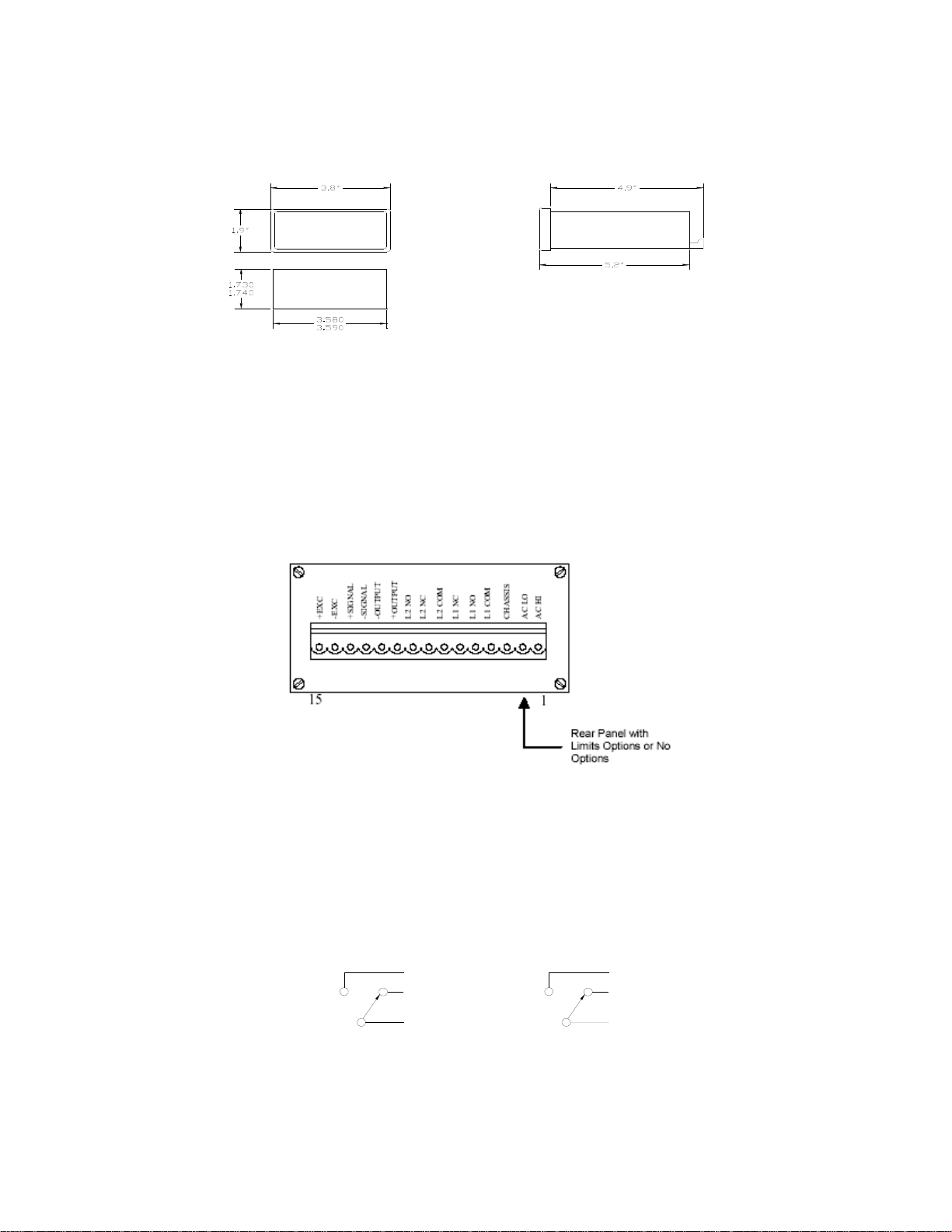
3.3 Wiring to The Sensor
All connections to the DFI 7000 are made through the rear-panel 15-pin connector. Terminal 1 is AC HI; terminal
15 is + EXC. This connector may be separated from the DFI for wiring by pulling on it gently. Connect the straingage sensor to the DFI 7000’s last four terminals, marked (+) EXC.,(-) EXC., (+) SIGNAL and (-) SIGNAL terminals,
respectively.
The DFI 7000 will accept strain-gage transducers with bridge impedances of 350 ohms or greater. Wires from the
transducer may be pushed into the terminal using a small screwdriver.
CAUTION: The connector can be inserted incorrectly. Fluted side down. Flat side is up! Incorrect insertion of this
connector will result in extreme circuit damage.
3.4 Wiring The Output
If the 0-5V output of the DFI 7000 is to be used, wire to terminals 10 and 11, marked +OUTPUT and –OUTPUT.
Observe the correct polarity.
3.5 Wiring To The Optional Limits
The DFI 7000 utilizes relay output limits that are energized when the signal level exceeds the limit setting. The
COMMON, NORMALY OPEN, and NORMALLY CLOSED contacts for the L1 limit set are on terminals 4, 5 and 6
respectively and for the L2 limit set on terminals 7, 9 and 8. The relays are rated at 24 volts, 1.0 amp (noninductive) or 48V, 0.5 amp (non-inductive).
NO
NC
COM
LIMIT ONE (L1)
LIMIT TWO (L2)
NO
NC
COM
3.6 Wiring To The Optional Peak Detector
The DFI 7000 is available with an optional peak detector module. This circuit will detect the highest positive value,
which has been attained since the peak detector was last reset. Reset may be accomplished by pressing the RST
CF11 3 V-May 2003-008-0186-00
Page 4

button on the front panel, or by interconnecting the RESET and COMMON terminals momentarily on the rear
connector.
Further, the PEAK OUT terminal will constantly monitor the peak detector output signal; the OUTPUT terminals will
monitor the amplifier output normally, but will shift to monitor the output of the peak detector when one of two
conditions occurs:
1. The front- panel PK button is pressed, or
2. The MODE SEL and COMMON terminals continuously on the rear panel are interconnected. The AMP OUT
terminal continuously monitors amplifier output and is not affected by the peak detector.
L
N
T
T
L
L
O
U
U
A
A
P
P
N
C
C
G
X
I
X
S
E
E
-
+
+
M
T
N
T
G
U
I
S
O
-
-
.
M
U
C
.
O
O
C
N
+
T
T
E
U
S
S
T
E
E
D
S
O
E
M
R
I
U
O
S
O
K
P
A
M
E
P
A
I
O
S
H
L
A
C
C
H
A
A
C
15
Rear Panel w ith Peak Option
1
3.7 Wiring to The Optional Track-And-Hold
The DFI 7000 is available with an option Track-and-Hold unit. This circuit will permit the output signal to closely
track the input signal. The HOLD function is engaged after which the last value obtained is held. The unit may be
placed in “hold” by interconnecting the rear panel HOLD and COMMON terminals, or by switch action on the front
panel. Placing the unit in “hold” will cause the output signal to lock on its last value prior to the ‘hold” condition.
L
A
A
N
C
X
E
+
N
C
G
G
I
X
I
S
S
E
+
-
-
O
U
U
P
P
M
T
T
U
O
-
.
M
U
C
.
O
O
C
N
+
N
T
T
L
15
Rea r P a n e l with T ra c k & H o ld Optio n
T
S
I
U
S
O
D
.
P
.
L
C
.
N
C
M
O
.
A
H
N
I
O
S
L
H
A
C
C
H
A
A
C
1
3.8 Power Connections
AC power is connected to the unit on terminals 1, 2 and 3. Observe that the AC LO terminal (#2) is connected to
the AC power line neutral (white wire). The AC HI terminal (#1) connects to the “hot” side of the AC power (black
wire). Terminal #3 is chassis ground (green wire). 110 volts, 60 Hz. Is the normal power for the DFI 7000, but 220
volts, 50 Hz. may be provided through jumpering on the Main Board. Contact COOPER for instructions on this
modification.
4.0 INTIAL ADJUSTMENTS/SETUP
Figure 1 – DFI 7000 Control Locations
4.1 Zero Adjustment
The adjustment of the no signal zero indication is made first. For all of the adjustments that follow, the transducer
attached to the unit should not have any applied pressure or load. If the transducer is an absolute pressure unit, it
should be calibrated under a vacuum. Otherwise, the unit will read the present local barometric pressure (approx.
CF11 4 V-May 2003-008-0186-00
Page 5

14.7 psi) and adjustment cannot be made using the ZERO adjustment only.
1. Remove the bezel and front panel with a small screwdriver.
2. Apply power to the DFI 7000. About 10 minutes warm-up is sufficient.
3. Adjust the COARSE ZERO potentiometer (see figure 1) to give an output voltage on terminals 10 and 11 of
zero. Then adjust the FINE ZERO to bring this value to exactly zero.
4.2 Span Adjustment
Span adjustment calibrates the gain of the amplifier section of the Signal Conditioner Board to provide the proper
voltage output for a given pressure or load. The shunt calibration feature allows the span to be properly set-up
without applying a known pressure or load to the transducer. This form of span adjustment will be described first,
followed by a method for calibration when the shunt calibration value has not been determined.
4.2.1 Span Adjustment With Shunt Calibration
A Transducer Calibration Record is normally shipped by all manufacturers of transducers with their products. The
full scale output and the shunt calibration output of unamplified transducers are reported on the Certificate of
Calibration in millivolts per volt (mv/v). Calculate as follows:
Shunt Cal Output in mv/v
Full-Scale Output in mv/v
EXAMPLES:
Using the calibration and full-scale output of the DFI 7000 (5V) provides:
1.4883 mv/v
1.8888 mv/v
After this calculation is made, proceed as follows:
1. Connect a meter to the output terminals (10, 11) on the rear connector.
2. Depress the SHUNT CALIBRATION button (See figure 1).
3. Adjust the COARSE SPAN control to give the approximate output voltage value calculated above.
4. Adjust the FINE SPAN control to give the exact output value calculated above.
After making these adjustments, a full scale pressure or load to the transducer will produce a 5-volt output from the
DFI 7000.
Note: The Shunt Cal Output provided by the Transducer Calibration Record is determined using a particular value
of Shunt Cal resistor. That value is also specified on the Transducer Calibration Record. It is necessary that the
same value of resistor be installed to produce the same results. The normal value used by COOPER for
transducers is 59,000 ohms (59k). This value is installed in the pin jacks provided on the Signal Conditioner Board.
If the transducer being used has a different value specified for its shunt cal resistor, it will be necessary to install
this value in the jacks provided on the Signal Conditioner Board. A procedure for accomplishing this is given in the
section entitled “Changing the Shunt Calibration Resistor.
x 5V = 3.939 volts
x Full-Scale Output = Output Voltage
4.2.2 Span Adjustment, Without Shunt Calibration
If the transducer shunt calibration output is not specified or not known, span can still be adjusted, but a known
pressure or load must be applied to the transducer. The applied pressure should be as close to the full-scale value
as possible, so that tiny errors in slope are not amplified by the ratio of full-scale to calibration point values.
Calculate the expected output of the DFI 7000 as follows:
Known Pressure or Load
Full Scale Pressure or Load
Once this calculation is made, proceed as follows:
1. Connect a meter to the output terminals (10, 11) on the rear connector.
2. Apply the known pressure or load to the transducer.
3. Adjust the COARSE SPAN control to give the approximate output voltage value calculated above.
4. Adjust the FINE SPAN control to give the exact output value calculated above.
X Full Scale Output = Output Voltage
CF11 5 V-May 2003-008-0186-00
Page 6

4.3 Scaling Adjustment
Scaling adjustment permits the DFI 7000 to display values in the engineering units desired by the customer.
Adjustment can be made either with shunt calibration or with a known pressure or load on the transducer. Perform
the scaling adjustment right after the span is adjusted, using the same output voltage to assist in calibration of
scaling.
First, determine the desired full-scale value of a 15,000-pound unit load cell. The desired full-scale value would be
15,000 since a 41/2 digit indicator is capable of indicating a maximum of 19,999 counts. Calculate the expected
display value based on the voltage calculated in the span adjustment steps 4.2.1 or 4.2.2) as follows:
Shunt Cal Output in mv/v
Full Scale Output in mv/v Value Value
x Full Scale Display = Shunt Cal Display
EXAMPLE:
1.4883 mv/v x 15,000 lbs. = 11,819 lbs.
1.8888 mv/v
After this calculation is made, proceed as follows:
1. Depress the SHUNT CALIBRATION button (see figure3).
2. Adjust the SCALING potentiometer to yield the displayed value calculated above (11819 in the example).
3. Place the jumper in the proper place on the Display Board to locate the decimal point as illustrated in Figure 2.
4. Reinstall the front panel and bezel.
Figure 2 – Decimal Points
5.0 OPERATIVE ADJUSTMENTS
Operative adjustments are those adjustments that may be made from time in normal operation. These include
“tweaking” the FINE ZERO and the FINE SPAN if these have moved, and setting the LIMITS potentiometers.
5.1 Fine Zero Adjustment
Transducers usually have some small amount of zero drift, usually the result of temperature change at the
transducer itself. With no pressure or load on the transducer, the zero may be readjusted to read zero by use of
the front panel ZERO adjustment
5.2 Fine Span Adjustment
After the FINE ZERO is readjusted, press the SHUNT CAL button to determine if the span is correct. If it needs
adjustment, use the SPAN adjustment on the front panel.
6.0 CHANGING THE SHUNT CALIBRATION RESISTOR
To change the Shunt Calibration Resistor, it is necessary to remove the Signal Conditioner Board from the Main
Board. The steps involved are:
1. Unplug the AC power and remove the rear connecter.
2. Remove the bezel and front panel (lens).
CF11 6 V-May 2003-008-0186-00
Page 7

3. Carefully pull the Main Board out of the unit. All boards will come out simultaneously.
4. Gently remove the Signal Conditioner Board from the Main Board.
5. Remove the Shunt Calibration resistor from the Signal Conditioner Board, and replace it with the proper value.
6. Replace the Signal Conditioner Board onto the Main Board.
7. Slide the board assembly into the case.
8. Reinstall the front panel (lens) and bezel.
9. Reinstall the rear connector.
Figure 3 – DFI 7000 Signal Conditioner Board
7.0 OPTIONS
High/Low Limits, Peak Detection, or Track-and-Hold option cards are available as factory or field-installable
options. Due to the small size of the DFI 7000, only one of these features can be installed in the same unit. To
install an option card, proceed as follows:
1. Unplug the AC power and remove the bezel and front panel.
2. Carefully pull the Main Board out of the unit. All boards will come out simultaneously.
3. Remove the plug-in jumper from the otherwise empty socket parallel to vertical Signal Conditioner Board. This
jumper must be reinstalled on Pins 6 and 7 (counting from the front) if the unit is to be operated without an
option card installed.
4. Install the option card on the Main Board and slide the board assembly into the case..
5. Install the new front panel associated with the option, and reinstall the bezel.
7.1 High/Low Limits Option
The DFI 7000 Limits Option allows the transducer signal to be continuously compared to two adjustable set points
called “limits.” The high limit is L1; the low limit is L2. The Limits Option uses relay outputs, which are energized
when the signal level exceeds the limit setting as illustrated in figure 4. LED indicators, located below the L1 and
L2 pushbuttons, also light and are visible through the front cover when the limit is exceeded. (See Sec.3.5 for relay
wiring.)
High
Setpoints
High - Off
l
a
n
g
i
S
Low - On
High - On
Low - On
Low
Setpoints
High - Off, Low - Off
On = Energized, Off = De-energized
Figure 4 – How Limits Work
CF11 7 V-May 2003-008-0186-00
Page 8

7.1.1 Setting The Limits Adjustments
Proceed to adjust as follows:
1. Unplug the AC power and remove the bezel and front panel with a small screwdriver.
2. Depress the desired LIMITS pushbutton (L1 or L2) to display the current setting of the limit detector.
3. Adjust the proper (L1 or L2) limits potentiometer to give the desired limits value on the display.
4. Reinstall the front panel and bezel.
7.1.2 Limit Polarity And Hysteresis
If a limit de-energizes at the same level at which it is energized, a noisy input signal will cause the limit to oscillate,
eventually destroying the relays. For this reason, the DFI Limits Option contains “hysteresis,” a 1% difference
between the energizing point and the de-energizing point of the limit. This 1% difference should always be
between the limit point and zero. For a positively set limit, the signal would rise, activating the limit. When the
signal then drops, it must drop to 1% below the limit setting before the relay will de-energize. For negative
setpoints, where the setting of the limit is a negative value, it is necessary to reverse the hysteresis polarity. (See
figure 5.) At the factory, all limit hysteresis jumpers are set for a positive setpoint. If a negative setpoint is to be
used, proceed as follows:
1. Unplug the AC power and remove the bezel, front panel, and Main Board.
2. Remove the Limits Option Board.
3. Locate the hysteresis jumper for the particular limit (either high or low). Place the jumper in the correct location
to correspond to the limit setting for this limit.
4. Replace the Limits Option Board onto the Main Board.
5. Place the Main Board back into the case; reinstall the front panel and bezel.
Figure 5 – Hysteresis Jumpers On Limits Option Board
7.2 Peak Detector Option
The DFI 7000 Peak Detector Option detects the highest positive value that has been attained by the signal since
the peak detector was last reset. Reset may be accomplished by pressing the RST button on the front panel, or by
interconnecting the RESET and COMMON terminals momentarily on the rear connector. Further, the PEAK OUT
terminal will constantly monitor the peak detector output signal; the AMP OUT terminal and the display will monitor
the amplifier output normally, but will shift to monitor the output of the peak detector when one of two conditions
occurs:
1. The front panel PK button is pressed upward (momentary) or downward (locking).
2. The MODE SEL and COMMON terminals on the rear panel are interconnected.
7.3 Track-And-Hold Option
The DFI 7000 Track-and-Hold Option permits the DFI to stop tracking an input signal upon command. This
command can be issued by completing a contact closure remotely, or by front panel pushbutton.
When the Track-and-Hold feature is in the “hold” mode, the front panel HOLD light will be lighted. The HOLD
button on the front panel works alternately, so that one push will deactivate it. Potentiometers on Track-and-Hold
board permit small errors of zero and span to be turned out, so that true tracking results.
If it is desired that the “hold” feature be activated by rear panel means, connection of the HOLD terminal with the
COMMON terminal will cause the unit to go into HOLD mode. The OUTPUT signal terminals (rear connector) will
CF11 8 V-May 2003-008-0186-00
Page 9

track the input signal unless the HOLD mode is active. The AMP OUT terminal will always track the input signal
regardless of the condition of the HOLD signal.
8.0 TROUBLESHOOTING GUIDE
Symptom/Problem Action/Troubleshooting
Erratic Display Check electrical connections for continuity and wiring code for pin layout.
No Display/No Output Voltage Check power connections per instrument Instructions.
Blinking Display Indicates a signal level greater than full-scale; make sure wires are all
connected, and transducer is within its range.
Incorrect Readout Value Check transducer range on label. Verify that system was set-up per
instructions. Review set-up procedure. Refer to transducer
troubleshooting guide and verify that transducer operates properly. Use
Shunt Cal to verify calibration.
Limit 1 or 2 fails to trip relay at
setpoint
Peak detector will not reset or will
not hold peak value
Track-and-Hold unit will not hold
signal when front switch is pushed
Verify that limit card is properly installed; check normally open, common,
and normally closed contacts on rear-panel connector for proper wiring.
Verify that Peak Detector Card is properly installed; check Mode Sel and
common terminal on rear-panel connector for proper wiring.
Verify that track-and-hold card is properly installed; check Hold and
Common terminals on rear-panel for proper wiring. Verify that the HOLD
light is coming on in the hold mode.
CF11 9 V-May 2003-008-0186-00
Page 10

9.0 WARRANTY REPAIR POLICY
Limited Warranty on Products
Any Cooper Instruments product which, under normal operating conditions, proves defective in material or in
workmanship within one year of the date of shipment by Cooper will be repaired or replaced free of charge provided
that a return material authorization is obtained from Cooper and the defective product is sent, transportation
charges prepaid, with notice of the defect, and it is established that the product has been properly installed,
maintained, and operated within the limits of rated and normal usage. Replacement or repaired product will be
shipped F.O.B. from our plant. The terms of this warranty do not extend to any product or part thereof which, under
normal usage, has an inherently shorter useful life than one year. The replacement warranty detailed here is the
buyer’s exclusive remedy, and will satisfy all obligations of Cooper whether based on contract, negligence, or
otherwise. Cooper is not responsible for any incidental or consequential loss or damage which might result from a
failure of any and all other warranties, express or implied, including implied warranty of merchantability or fitness for
particular purpose. Any unauthorized disassembly or attempt to repair voids this warranty.
Obtaining Service under Warranty
Advance authorization is required prior to the return to Cooper Instruments. Before returning the item, contact the
Repair Department c/o Cooper Instruments at (540) 349-4746 for a Return Material Authorization number.
Shipment to Cooper shall be at buyer’s expense and repaired or replacement items will be shipped F.O.B. from our
plant in Warrenton, Virginia. Non-verified problems or defects may be subject to a $100 evaluation charge. Please
return the original calibration data with the unit.
Repair Warranty
All repairs of Cooper products are warranted for a period of 90 days from date of shipment. This warranty applies
only to those items that were found defective and repaired; it does not apply to products in which no defect was
found and returned as is or merely recalibrated. It may be possible for out-of-warranty products to be returned to
the exact original specifications or dimensions.
* Technical description of the defect: In order to properly repair a product, it is absolutely necessary for Cooper to
receive information specifying the reason the product is being returned. Specific test data, written observations on
the failure and the specific corrective action you require are needed.
CF11 10 V-May 2003-008-0186-00
 Loading...