

Page 1

DFI 3900
PROCESS METER
USER’S GUIDE
www.cooperinstruments.com
PH: (540) 349-4746 • FAX: (540) 347-4755
Page 2

CONTENTS
1.0 INTRODUCTION AND DESCRIPTION..................................................................................1
1.1 Unit Description ..............................................................................................................................1
1.2 Dimensional Drawings ...................................................................................................................1
2.0 SAFETY SUMMARY..............................................................................................................1
2.1 Main Board/Bottom (P1) and Option Board/Top (P2) Pin Outs...................................................2
2.2 Serial RS-232C Connections on P1 (Main bd) connector............................................................3
3.0 OPERATION AND PROGRAMMING.....................................................................................3
3.1 Front panel Keys.............................................................................................................................3
3.2 Setup Mode Key Functions............................................................................................................4
3.3 Run Mode Key Functions...............................................................................................................4
3.4 Programming Tips ..........................................................................................................................7
3.5 Enter Setup......................................................................................................................................7
3.6 Main Programming Branches........................................................................................................8
3.7 Channel Setup Programming Branch...........................................................................................8
3.8 Output Setup Programming Branch............................................................................................10
3.9 Display Setup Programming Branch...........................................................................................11
3.10 Special Features Programming Branch....................................................................................11
4.0 OPTIONS .............................................................................................................................13
5.0 SPECIFICATIONS................................................................................................................14
DFI 3900 SERIAL COMMUNICATIONS....................................................................................16
WARRANTY REPAIR POLICY..................................................................................................18
DFI 3900 07/31/03 ii CF 58
Page 3
1.0 INTRODUCTION AND DESCRIPTION
1.1 Unit Description
The single input 3900 intelligent process meters feature 5 ½ digit resolution, 6 digit display, 5 front key operation
and a NEMA 4X, industrialized aluminum case. One Form A relay is provided standard for use as an Alarm output.
The 3900 emphasizes the features required in today’s applications, especially scaling of the meter to display in
engineering units. Two methods are provided to scale the meter: no calculation scale and offset, and load
calibration.
Models:
DFI 3900 – 4 analog inputs with 5
Options:
3900-1 4 Individual Analog Outputs & Excitation Output
(Available soon)
3900-2 Serial RS-232C Communication
3900-3 3 Form C Relays
3900-24P 5 VDC
Inputs:
Process inputs selectable for 20mA, 30mV, 100mV, 200mV, 2V, +10V input
The setup of the meter is fully programmed through the front panel keypads. The 115VAC or 220VAC selection is
accomplished through the selection of an internal jumper connection.
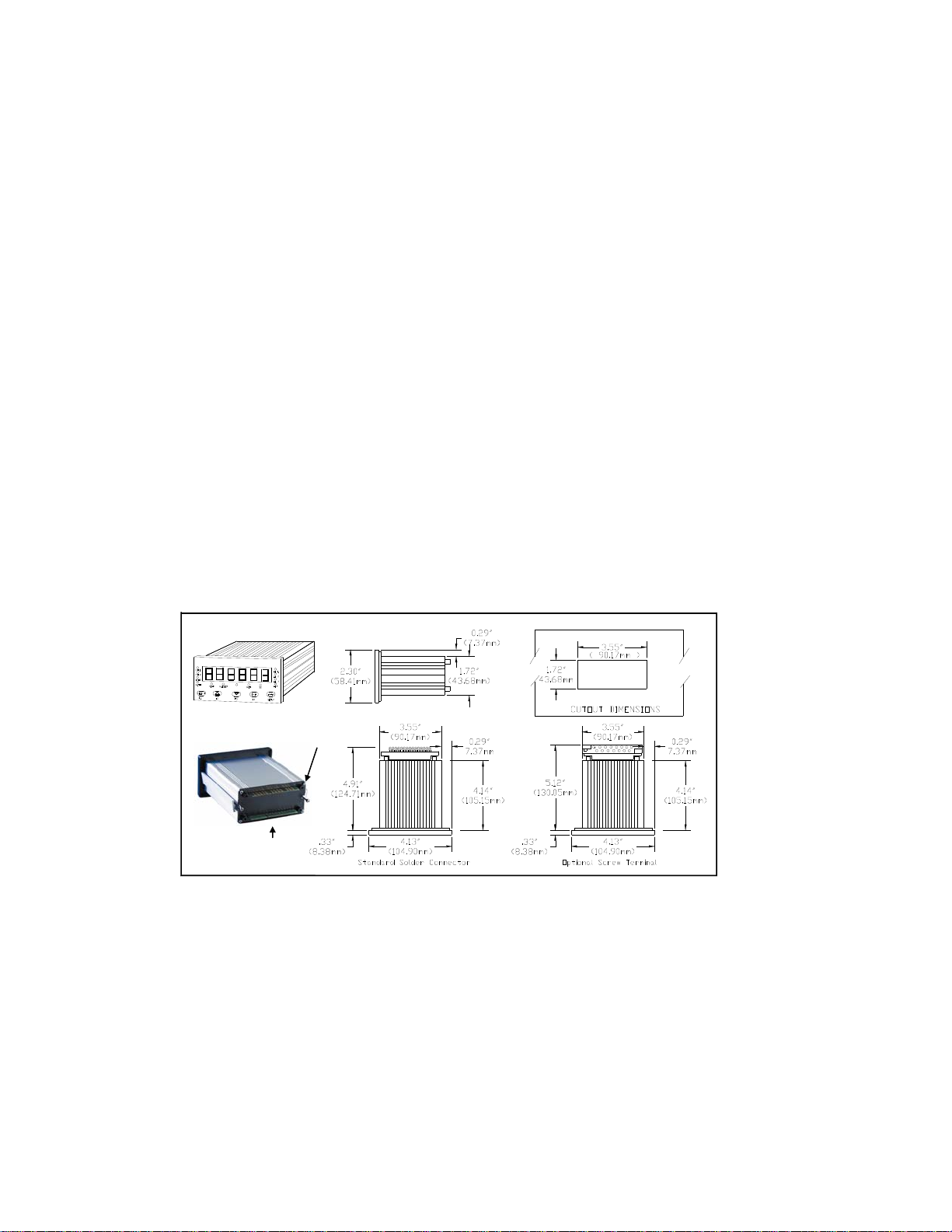
1.2 Dimensional Drawings
th
channel math
P2 (Option
Board/Top
Connector)
P1 (Main Board /Bottom
Connector)
2.0 SAFETY SUMMARY
All safety related regulations, local codes and instructions that appear in this literature or on equipment must be
observed to ensure personal safety and to prevent damage to either the instrument or equipment connected to it. If
equipment is used in a manner not specified by the manufacturer, the protection provided by the equipment may be
impaired.
Do not use this unit to directly command motors, valves, or other actuators not equipped with safeguards. To do so
can be potentially harmful to persons or equipment in the event of a fault to the unit.
DFI 3900 07/31/03 1 CF 58
Page 4
CAUTION: Read complete CAUTION: Risk of Electric shock
Instructions prior to installation
And operation of the unit.
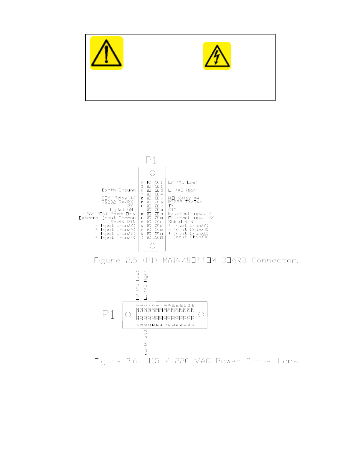
The unit must be properly grounded. Ground connection is tied to the Main Board “P1” connector pin # C.
Fuse replacement must be performed with power disconnected. Use only the same type fuse. The fuse must be a
TR5 microfuse, Time Lag (T), 1 amp, 250VAC. Fuse location shown in section 1.3
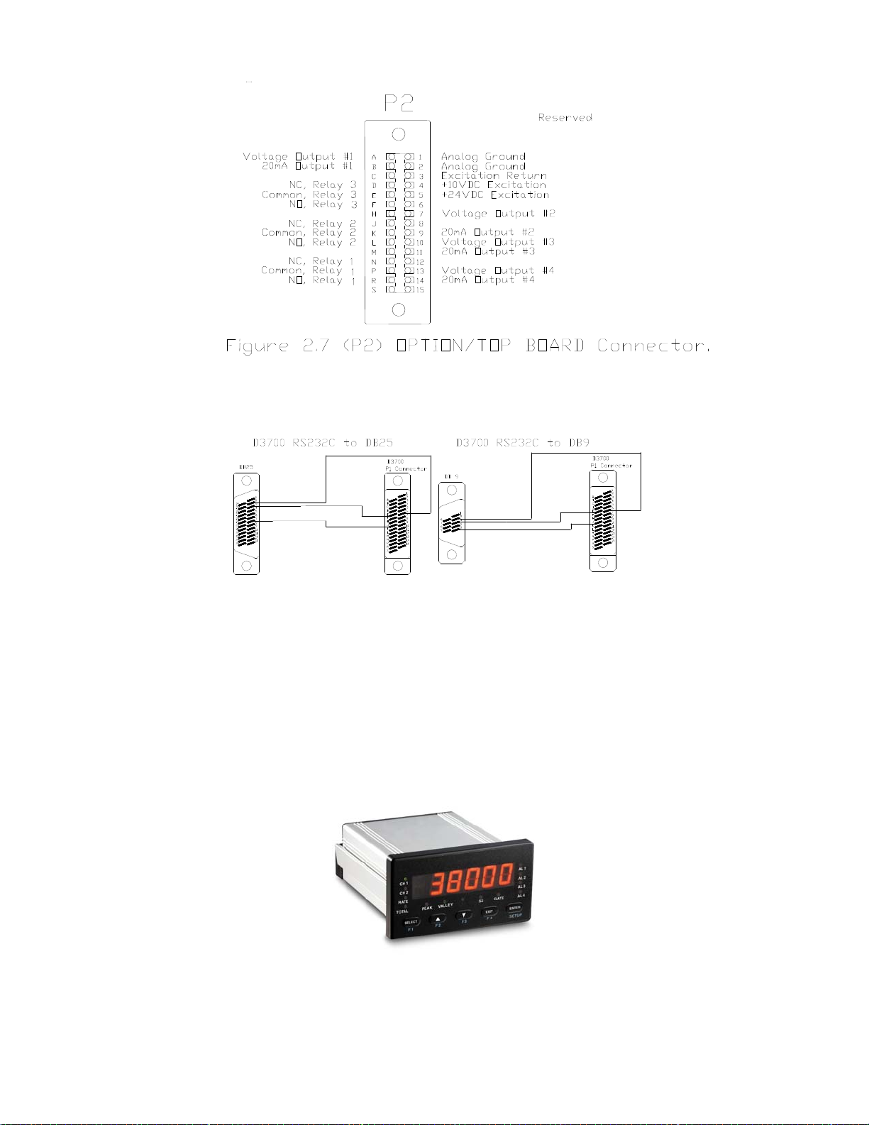
2.1 Main Board/Bottom (P1) and Option Board/Top (P2) Pin Outs
DFI 3900 07/31/03 2 CF 58
Page 5
2.2 Serial RS-232C Connections on P1 (Main bd) connector
RS232 Connection to A 9 pin Connector
From P1 Connector to 9 pin connector
Pin F to Pin 3
Pin J to Pin 5
Pin 6 to Pin 2
3.0 OPERATION AND PROGRAMMING
3.1 Front panel Keys
DFI 3900 07/31/03 3 CF 58
Page 6

The front panel keyboard has two modes of operation - SETUP and RUN
SETUP MODE KEYS
SELECT ▲ ▼ EXIT ENTER
RUN MODE KEYS
F1 F2 F3 F4 SETUP
3.2 Setup Mode Key Functions
1. SELECT KEY (→ on flow chart indicates to use this key)
• Selects choice of functions within the menu you are setting up.
o Moves you left/right in the program menu.
• When entering numeric data, it allows the selection of digit to be changed.
o Indicated by digit flashing.
• When selecting decimal point, it moves the decimal point location.
2. UP ARROW KEY
• When entering numeric data, it increments the current value of the flashing digit by one with each push.
3. DOWN ARROW KEY
• When entering numeric data, it decrements the numeric value of the flashing digit by one with each push.
4. EXIT KEY
• If at a Main branch prompt (CODE, CHAN, OUTPUT, DISPLY or SPEC), it exits to you back to RUN mode.
• If in a programming branch, it returns you to Main branch prompt.
NOTE: It does not store data to memory on its return. ENTER key should be pushed first to store selected
entry, then EXIT key.
5. ENTER KEY (↓ on flow chart indicates to use this key)
• Enters selected Main program branch.
o Moves you down in the program branch menu.
o Menu steps can be skipped by repeatedly pushing ENTER key till desired menu step is reached.
• Enters selected choices, numeric data or decimal point, it store the value and advances to next step in the
program menu.
3.3 Run Mode Key Functions
A. Entering SETUP
Push and hold SETUP key for 4 seconds. Meter will first display “SET CH” then display “CODE” or flash
“SETUP then display “CHAN”.
• “CODE” is flashed with 00 if a lockout code has been set under the Main program branch heading SPEC,
CODE menu.
o The preset lockout must be entered at this time. If wrong code is entered or if no code is entered within 20
seconds, meter will return to RUN mode.
o Upon correct lockout code entry, meter enters the SETUP mode.
o The unmarked yellow LED just above the Down/F4 key will light, indicating you are in the SETUP mode.
• If no lockout code, “SETUP” flashed then “CHAN” displayed, indicating you have entered the SETUP mode.
If no key is pressed within 20 seconds, meter will return to RUN mode.
B. If SETUP key pushed and released meter will enter Select Channel program.
• “SET CH” (SET CHANNEL) will be display.
o Push F1 to select Channel 1 for display
o Push F2 to select Channel 2 for display
o Push F3 to select Channel 3 for display
o Push F4 to select Channel 4 for display
DFI 3900 07/31/03 4 CF 58
Page 7

C. FINE TUNE OFFSET/ZERO
Push and hold SETUP key, then DOWN key pushed at the same time and then both keys released.
This program allows the adjustment of the low input display directly from the run mode of the selected channel.
It directly acts as a zero offset. This command allows for “On the fly” adjustments of the zero values. The value
entered will become the display value for the last measured input.
• Display will flash "OFFSet1" (CHAN 1), or "OFFSet2" (CHAN 2)
• Display with last measured input and least significant digit flashing will appear.
o Push UP key to increase display
o Push DOWN key to decrease display
o Push SELECT key to select digit to be changed
o Push EXIT key to return to RUN mode
D. FINE TUNE SCALE/SPAN
Push and hold SETUP key, then UP arrow key pushed at the same time and then both keys released.
This program allows the adjustment of the high input display directly from the run mode of the selected
channel to an adjusted scaled value.
• Display will flash "ScALE"
• Display with live input and with most significant digit flashing will appear.
• Push UP key to increase display
• Push DOWN key to decrease display
• Push EXIT key to return to RUN mode.
Note: You are fine-tuning the least significant digits.
E. USER PROGRAMMABLE MENU LOCKOUT.
To enter, push and hold SETUP key, then enter lockout code “55”. This program allows user to disable/lockout
the following menus from the SETUP program. When the menus are programmed to be locked, the unit will
display “disabl” when you try to enter the menu.
NOTE: A code # must be preprogrammed under SPEC, CODE to get the prompt for the code value.
To disable one or more of the selections add the values from the table and enter that number. If 0 is entered, all
programs under that heading are enabled.
• “LeveL1” is flashed with current selected number, valid values 0-15
0 Don’t Skip any branches
1 Skip all channel programs "CHAn"
2 Skip all output programs "OutPut"
4 Skip all display program "dISPLy"
8 Skip all special programs "SPEC"
Example: Enter number 12 to skip DISPLY and
SPEC branches from normal setup selections.
Once number is entered, display will go to next
branch that is not skipped.
• “CHAN1”, (Only if CHAn is not disabled from above), is flashed with current selected number. Valid values 0-
15.
0 Don’t disable any channel 1
1 Skip input range selection "InPut"
2 Skip user calibration branch "USEr"
4 Skip input calibration branch "InPut"
8 Skip shunt calibration branch"Shunt"
• “CHAN2” (Only if CHAn is not disabled from above) is flashed with current selected number. Valid values 0-7.
0 Don’t skip channel 2
1 Skip input range selection "InPut"
DFI 3900 07/31/03 5 CF 58
Page 8

2 Skip user calibration branch "USEr"
4 Skip input calibration branch "InPut"
• “CH3” (Only if CHAn is not disabled from above) is flashed with current selected number. Valid values 0-1.
0 Don’t skip channel 3
1 Skip channel 3 "CHAn 3"
• “OutPut” (Only if OutPut is not disabled from above) is flashed with current selected number. Valid values 0-
31.
0 Don’t disable any output menus
1 Disable Alarm 1 menu
2 Disable Alarm 2 menu
4 Disable Alarm 3 menu
8 Disable Alarm 4 menu
16 Disable the Source menu
• “SPEC” (Only if SPEC is not disabled from above) is flashed with current selected number. Valid values 065535 (default 32768)
0 Don’t disable any menus
1 Disable ‘F1 SET’
2 Disable ‘F2 SET’
4 Disable ‘F3 SET’
8 Disable ‘F4 SET’
16 Disable ‘r In 1’
32 Disable ‘r In 2’
64 Disable ‘r In 3’
128 Disable ‘r In 4’
256 Disable ’20 PT’
512 Disable ‘PEAK 1’
1024 Disable ‘PEAK2’
2048 Disable ‘SCALE2’
4096 Disable ‘CODE’
8192 Disable ‘dEFAUL’
16384 Disable ‘rESoLU’
32768 Disable ‘A2d’
• If EXIT key is push at any of the 6 main heading, exit back to run mode.
• If EXIT key is push while in a main branch, exit back to that main branches heading.
• If SELECT key is push while at main branch heading, advance to next main branch.
• When “skip code number” is entered by ENTER key, advance to next branch heading.
F. F1, F2, F3 and F4 keys
The RUN mode keys (F1-F4) functions are selected in the SETUP mode under the Main program branch
heading SPEC. The functions are described under the SPECIALS FEATURES PROGRAMMING BRANCH
section of the manual (See pg. 15). The following are the available selections.
• "Alarm 1" through "Alarm 4"
• "TARE 1","TARE 2", "TARE 3", “TARE 4”
• "RESET"
• "CHANNEL 1, 2, 3, 4, or 5"
• "PEAK 1"
• "PEAK 2"
• "SCALE2"
• "NET"
• "HOLD” (Scan Mode)
DFI 3900 07/31/03 6 CF 58
Page 9

3.4 Programming Tips
→ SELECT Key This represents SELECT key on flow charts
↓ ENTER Key This represents ENTER key on flow charts
Numeric values are entered by:
• Entering a number in flashing digit with the “UP” and “Down” keys.
• Advance to the next digit using SELECT key. Enter value and advance using ENTER key.
ENTER key sets number into memory and advances to next program.
EXIT key :
1. From MAIN BRANCH heading, takes you back to run mode
2. From PROGRAM BRANCH, takes you back to MAIN BRANCH heading you are in.
TIMED OUT EXITS:
1. If no key is pushed within 20 seconds while at CODE or main branch heading, meter will automatically exit
back to run mode.
2. If no key is pushed within 2 minutes while in any other program branch, meter will automatically exit back to run
mode.
3.5 Enter Setup
• Press and hold SETUP key for 4 seconds. Meter will display “SEL CH” at first then will enter into the Setup
mode. The meter will display “CODE” or “CHAN”.
• “CODE” is flashed with 00 if a lockout code has been set under the Main program branch heading SPEC,
CODE menu.
• The preset code (1-40) must be entered at this time. If wrong code is entered or if no code is entered within
20 seconds, meter will return to RUN mode.
• Upon correct lockout code entry, meter enters the SETUP mode. The status LED between Valley and NET
will light indicating the meter is in the Programming/Setup mode.
• The unmarked yellow LED just above the Down/F4 key will light, indicating you are in the SETUP mode.
• If no lockout code, “SETUP” flashed, then “CHAN” displayed, indicating you have entered the SETUP mode.
If no key is pressed within 20 seconds, meter will return to RUN mode.
DFI 3900 07/31/03 7 CF 58
Page 10

3.6 Main Programming Branches
Run Mode
Press the
"ENTER" for
4 Sec.
Flashes
SEtuP/COdE
CHAn
Chan1,Chan2,
Chan3
setup routines and
calibrations are
under
this main menu.
Press &
release
"ENTER"
To move Side ways in the chart
below press the (SELECT) button.
To move down through the chart press
the (ENTER) key.
SEL CH
"F1"
Display
Channel
#1
Main
Programming
Branches
"F2"
Display
Channel
#2
OutPut DiSPlY SPEC
Quick Access F1-F4,
Code,Default settings.
Alarms,Analog
Ouput,
Setup are under this
menu.
Update Rates,
Filter,
and Snap functions
are set under this
menu.
"F3"
Display
Channel
#3
keys, Remote R1-R4
inputs, 20pt
Linearization,Peaks
1&2 ,Access
For more
Description
see Sec.
3.8
For more
description
see Sec.
3.9
See back page
for
complete Flow
Chart.
For more
description
see Sec.
3.10
For more
description
see Sec.
3.7
"CODE" is displayed if a lock out code has been programmed.
• If "CODE", then enter your Lockout Code number (1-99)
• If no "CODE" then "CHAn" is displayed
Use SELECT key to choose which branch you wish to enter. Then press ENTER key to select that branch to
program. Selections are: "Chan", "Output", "Disply", and "Spec".
3.7 Channel Setup Programming Branch
Press SELECT key to choose which channel you wish to program. Then press ENTER key.
CHAn 1 is input channel 1
CHAn 2 is input channel 2
CHAn 3 is input channel 3
DFI 3900 07/31/03 8 CF 58
Page 11

CHAn 4 is input channel 4
CHAn 5 is math channel
There are 5 separate channel setups. Four for the analog input channels (Channel 1, Channel 2, Channel 3,
Channel 4) and one for the math channel (Channel 5)
1. Channel 1 through Channel 4 Scaling and Offsetting methods to display in engineering units
• There are 2 methods to perform the setup of the Channels.
At the beginning of each of the calibration methods there is a display that shows the raw unscaled input
signal. This allows the user to verify the incoming signal is present and what value it is.
a. Method 1 (U CAl)
1. Raw input is displayed. For exact calibration purposes you can input the low and high inputs and
record their value for entry in the low and high input values below. Push ENTER key to advance.
2. "dEC Pt" selects decimal point. Push SELECT key for displaying decimal point selections and
ENTER key to confirm choice.
3. "In Lo" enter in low input value
4. "dSP Lo" (display low) enter in display value corresponding to low input value.
5. "In HI" enter in high input value.
6. "dSP Hi" (display high) enter in display value corresponding to high input value.
b. Method 2 (Ld CAL)
NOTE: Input Signal must be applied to the unit for low and high display values. The meter compares the
input signal to the display value entered and scales the meter based on the two inputs.
1. Raw input is displayed. This can be used to make sure the correct input is being applied and/or that
the meter is properly measuring it. Push enter to advance.
2. "dEC Pt" selects decimal point. Push SELECT key for displaying decimal point selections and
ENTER key to confirm choice.
3. "dSP Lo" (display low).
Either select "Yes" or "nO" here.
"Yes" allows you to apply corresponding low input signal to input and enter in corresponding low
display value. Push ENTER key to make displayed value equal input. If “NO” is selected it skips over
this program and leaves values to what they were.
4. "dSP Hi" (display high).
Either select "yES" or "nO"
If "yES" is selected, this allows you to apply corresponding high input signal to input and enter in
corresponding high display value. Push ENTER key to make displayed value equal input. If “NO” is
selected it skips over this program and leaves values to what they were.
5. "EnAbLE" (Enable). This enables the above calibration setup by the inputs. This allows for the low
value and high values to be set at different times and then enabled when both are complete.
• "NO" leaves calibration unchanged
• "YES" enables this calibration and overrides any previous calibration by the USER or SHUNT type
calibration.
2. Channel 5 (Math Channel)
a. "TyPE" Select for channel 5 to be one of following:
• "CHAn 1" channel 1’s raw input count
• "CHAn 2" channel 2’s raw input count
• “CHAn 3” channel 3’s raw input count
• “CHAn 4” channel 4’s raw input count
• "Add" Sum of Channel 1 and 2
• "Sub" Difference of channel 1 – 2
• “Div” Result of channel 1 ÷ 2
• “P1-P2” Peak1 – Peak2
• “AVG” AVG of Channel(1+2+3+4)/4
• “SUM” Sum of all 4 channels
• “MUL” Product of CH1 x CH2
b. Raw input is displayed. For exact calibration purposes you can input the low and high inputs and record
DFI 3900 07/31/03 9 CF 58
Page 12

their value for entry in the low and high input values below. NOTE: The low and high values are the result
of the above selected math formulas. Push ENTER key to advance.
c. "dEC Pt" selects decimal point. Push SELECT key for displaying decimal point selections and ENTER key
to enter choice.
d. "In Lo", enter in low input value
e. "dSP Lo", (display low) enter in display value corresponding to low inpt value.
f. "In HI", enter in high input value.
g. "dSP HI", (display high) enter in display value corresponding to high input value.
h. “ OFFSE” Enter an offsetting factor from –9999 to 9999, which is applied after the above scaling.
3.8 Output Setup Programming Branch
Push SELECT key to choose which output you wish to program. Then press ENTER key.
"AL AR" is the 4 alarm output setups, "AnALOG" is analog output setup
1. ALARMS
This setup menu programs the 4 alarms.
NOTE: Relays 1 through 3 are optional FORM “C” relays and located on the option/top board.
Relay 4 is standard FORM “A” relay and located on the main/bottom board.
a. "AL Ar" selects which alarm is to be programmed. Use SELECT key to view choices of alarms 1 through 4.
Use the ENTER key to enter choice.
Note: 1. Each alarm is treated completely independent thus allowing all 4 to be programmed with same
channel or different channels controlling one alarm.
2. Alarm one is different from one standpoint. It has the additional selection of "SAFE"(fail safe)
selection. The selection "SAFE" here controls relays 1 through 3
b. "CHAnEL" selects which channel alarm is being assigned to. Use SELECT key to view choice of channels.
Use ENTER key to enter choice.
c. "rELAY" selects which relay (1 through 4) is being programmed. Use SELECT key to view choices of
outputs. Use the ENTER key to enter choice.
NOTE: Relays 1 through 3 are optional and located on the option/top board. Relay 4 is standard and
located on the main/bottom board.
d. "TYPE" selects what type of alarm. Use SELECT key to view following choices. Use the ENTER key to
enter choice.
1. "ALAr HI" (alarm high) selects alarm to trigger when input goes over programmed set point.
2. "ALAr LO" (alarm low) selects alarm to trigger when input goes under programmed set point.
e. "SEt Pt" (set point) enter number at which alarm will occur.
• Set point can also be programmed from the RUN mode when an "F" key is assigned to display alarm. If
"F" key is held for @ 4 seconds, the display will start flashing the right hand digit signifying the new set
point can be entered.
Note: The corresponding front panel alarm LED is on when in alarm.
f. "HySt" (hysteresis/deadband) enter number. This number is added to a low limit or subtracted from a high
limit before an alarm condition is cancel. It is typically used to prevent alarm chatter. This is set under
Alarm # 1 for all Alarms.
g. "LatCH" selects alarm to latching or non-latching(follows input). If LATCHING is selected, alarm will remain
on till manually reset. Use SELECT key to view “YES” for latching and “NO” for non-latching. Use the
ENTER key to enter choice. Note: “reset” function programmable for front panel key or remote input, is
used to reset the latched alarm.
h. "SAFE" ("ALARM 1" ONLY) selects alarms 1 through 3 to be in a safe mode(de-energizes on alarm) or
standard (energizes on alarm). Use SELECT key to view “YES” for safe and “NO” for standard. Use the
ENTER key to enter choice. Note: This is used to determine what the alarms do when loss of power occurs
to meter. With "SAFE" selected alarm will turn on when power fails.
i. "FLASH" selects alarm to flash display when in alarm. Use SELECT key to view “YES” for flash display and
“NO” don’t flash display. Use the ENTER key to enter choice.
2. ANALOG OUTPUT
This setup menu programs the analog output/retransmission.
a. "SOUrCE" selects what the analog output will be based upon. Use SELECT key to view choices. Use
ENTER key to enter choice. After choice is entered then addition choices are entered.
for the fail safe operation.
DFI 3900 07/31/03 10 CF 58
Page 13

1. Selections are:
• "CHAn 1" Channel 1
a) "Gross" gross value
b) "nET" net value
c) "PEAK 1" peak 1 value
• "CHAn 2" Channel 2
a) "Gross" gross value
b) "nET" net value
c) "PEAK 1" peak 1 value
• "CHAn 3" Channel 3
a) "Gross" gross value
b) "nET" net value
c) "PEAK 1" peak 1 value
• "CHAn 4" Channel 4
a) "Gross" gross value
b) "nET" net value
c) "PEAK 1" peak 1 value
• "CHAn 5" Channel 5
a) "Gross" gross value
b) "nET" net value
c) "PEAK 1" peak 1 value
d) "dISPLy" Whatever is currently selected
b. "OuT" selects what the analog output will be
• "4-20" 4-20mA
• "0-10" 0-10VDC
c. "dSP Lo" enter what the low display value that will represent the low analog output value
d. "dSP HI" enter what the high display value that will represent the high analog output value
3.9 Display Setup Programming Branch
The Display section allows the user to select between two modes of operation, (NORMAL, or SCAN). The
NORMAL mode allows the display to show one channel continuously.
The SCAN mode allows the unit to scan the programmed channels at approx. 1sec intervals. The selection of
scanning is (Channel 1,2), (Channel 1,2,3), (Channel 1,2,3,4), or (Channel 1,2,3,4,5). By programming a function
key for “HOLD” allows the unit to scan the channels with a temporary hold of the scan mode when the function key
is pressed.
3.10 Special Features Programming Branch
Use SELECT key to choose which function you wish to program. Then press ENTER key.
• "F1 Set" thru "F4 Set" programs the RUN mode function of the 4 F keys
• "r in 1" thru "r in 4" programs the function of the 4 remote inputs
• "PEAK 1" programs the peak or valley function of each channel
• "PEAK 2" programs second the peak or valley function of each channel
• "SCALE2" programs the second scaling parameters of each channel
• "CodE" programs the lockout code for authorized entry into SETUP
• "dEFAUL" sets meter setup back to default setup
• "rEs" sets the resolution for the meter (4.5 or 5.5 digits)
• "A2d" - For factory use only
1. "F1 Set", "F2 Set", "F3 Set" and "F4 Set" - RUN MODE function key setup
This programs the function of the 4 front panel F keys.
A. "rESEt" assigns F key for resetting latched outputs
• Pushing F key will reset all relays in an alarm condition.
B. "SCALE2" assigns F key to initiate 2
nd
scaling to be applied.
DFI 3900 07/31/03 11 CF 58
Page 14

• Pushing F key will switch displayed channel to 2
• Front panel S2 LED will light to indicate 2
• Push F key while S2 is selected will change scaling back to initial scaling
• If different channel is selected while 2
nd
nd
scaling is selected, it will also use the 2nd scale factor applied to
nd
scaling.
scaling is applied.
it.
C. "nEt" assigns F key to switch displayed channel between gross and net
• Pushing F key will switch displayed channel to display net.
• Front panel NET LED will light to indicate NET is being displayed.
• Push F key while net is selected will change display back to gross.
• If different channel is selected while net is selected, it will also display net.
D. "PEAk 1" and "PEAk 2" assigns programmed peak function to F key
• Pushing F key will display the assigned peak function. If peak was assigned peak LED on front panel will
also light. If Valley then valley LED will light.
• Pushing F key for 4 seconds will reset the peak/valley.
E. "ALAr 1" thru "ALAr 4" assigns alarm function to F keys
• Pushing F key displays current alarm set point
• Pushing F key for 4 seconds allows set point value to be changed.
Current set point is displayed with the right most digit flashing. The set point can now be changed with
the UP and DOWN keys. Select digit to be changed with SELECT key. Press ENTER key to enter new
value into memory and return to RUN mode
F. "tArE 1", "tAreE 2", "tArE 3", "tArE 4” assigns F key for tare function. 1 for channel 1, 2 is for channel 2, 3 is
for channel 3, 4 is for channel 4.
• Pushing F key will zero the channel for the input present.
• Pushing F key for 4 seconds will reset the tare value to zero.
• "CHAn 1" assigns F key to display channel 1
• "CHAn 2" assigns F key to display channel 2
• "CHAn 3" assigns F key to display channel 3
2. "r in 1", "r in 2", "r in 3", and "r in 4" remote inputs. RUN mode remote/external input setup
The 4 Remote input functions are selected under the Main program branch heading "SPEC". The following are
enabled by a TTL level applied to the input.
• "RESEt" - Resets latched relays
• "TarE" - Zeros display for channel being displayed.
• "HOLd" - Freezes display and suspends measurements
• "SCALE2" - Selects second scaling to be applied to channel being displayed. S2 light on front panel is lit.
• "LOCk" - Locks out access to the SETUP programs
• "PEAk 1" - Display PEAK 1
• "Peak 2" - Display PEAK 2
• "Alarm" - Disables alarms. Meter functions normally but no alarms are activated when they go beyond their
preset limits.
• "dEC Pt" - Selects the decimal point programmed
• "CHAn" - Selects the channel programmed
• "Preset" - Resets both peak and valleys.
• "Gross" - Displays Gross value of channel
• “PrinT” – Initiates a print of the current display through the RS-232C serial port. (T option required for this
function.)
3. "PEAK 1" and "PEAK 2" setup
Programs the functions of the 2 peak capture inputs. Each peak can be individually programmed.
"tYPE" Select if peak to be highest or lowest valley
"HI" High/Peak selection
"Lo" Low/Valley selection
"CHAn 1", "CHAn 2". "CHAn 3" Select channel to do peak on
4. "Scale 2" setup
DFI 3900 07/31/03 12 CF 58
Page 15

Programs the setup and assignment of the second scale factor. This would typically be used to switch the
display between English and Metric engineering units. The selection of scale 2 can be activated from a Front
Panel Key (F1 - F4) or a remote input. They must be programmed to perform the switch to scale 2 under the
"SPEC" branch programming.
"CHAn 1", "CHAn 2" select which channel the second scale factor is being setup for. Both channel 1 and
channel 2 can be setup for an individual second scale factor.
"dEC Pt" selects decimal point. Push SELECT key for displaying decimal point selections and ENTER key to
confirm choice.
"In Lo" enter in low input value
"dSP Lo" (display low) enter in display value corresponding to low input value.
"In HI" enter in high input value.
"dSP Hi" (display high) enter in display value corresponding to high input value.
5. Lock Out Code Setup
This enables the program of a lockout code (0 to 99) to limit the entry into the setup mode. Once a code is
entered here, it must be entered upon trying to enter the setup mode when the meter prompts for "CODE".
Setting the code to 00 disables the lockout code function.
"CodE" is flashed with the lock out code currently programmed. Enter in a new code or exit the program (EXIT
key).
6. DEFAULT program
This program is used for any of the following:
• Reset the meter back to the factory defaults.
• Set the user defined defaults into memory
• Reset the meter to the user defined defaults
"DEFAUL" default program prompt
"YES"/"NO" "No" to exit this menu
"Yes" if one of the 3 defaults is to be done. Continue to next step
"USEr"/"Fac"
• "FAC" (factory) allows the reset of the meter back to factory defaults. When the prompt "FacTrY" is
displayed, the SELECT key must be pushed and held (10 seconds) until the prompt "dONE" and returns
to "SPEC" branch. If any other key is push it will abort the default operation and return to "SPEC" branch.
• "Usr" (User) allows the setup of custom defaults or default to the custom defaults
• "StorE" allows the custom defaults to be set. This will set the defaults to the setup of the meter it is
currently programmed.
• "SET df" When this is displayed the SELECT key must be pushed and held until the "dONE" prompt.
Meter then returns to "SPEC" branch heading.
• "GET df" When this is displayed the SELECT key must be pushed and held until the "dONE" prompt.
This takes approximately 10 seconds. Meter then returns to "SPEC" branch heading.
7. Resolution selection
This allows user to select the resolution and speed. The selection applies to channel 1 and channel 2 inputs.
"rEs"
"4.5" selects resolution of 4 ½ digits at 60/second update
"5.5" selects resolution of 5 ½ digits at 60/second update
8. "A/D"
For Factory Use only
4.0 OPTIONS
The following options are available on the DFI 3900:
1. 3900-1 16 bit D/A analog output
2. 3900-2 RS-232C @ 9600 BAUD
3. 3900-3 3 each Form C relay outputs
3900-1:
DFI 3900 07/31/03 13 CF 58
Page 16

• 4 analog outputs with menu selection of 0-20mA, 0-10VDC
• Update rate of 5/second
• Resolution - 16 bit D/A
• Located on the option/top printed circuit board
• Located on the option/top printed circuit board
3900-2:
• Serial RS-232C Communication.
• Configuration of 9600 baud, No Parity Check, 8 DATA Bits, with CTS handshaking available.
3900-3:
• 3 each form C (single pole double throw) relays rated at 5 amp @ 240VAC, 5amps @ 30VDC.
• Located on the option/top printed circuit board
3900-24P:
• 5 Volt Excitation
5.0 SPECIFICATIONS
±20 mA
Accuracy 0.02% 0.02% 0.02% 0.02% 0.02% 0.02%
Zero Drift autozero Autozero Autozero autozero autozero autozero
Span Drift 10 ppm/°C 10 ppm/°C 10 ppm/°C 10 ppm/°C 10 ppm/°C 10 ppm/°C
Input
Impedance 50 Ohms 10 Mohm 10 Mohm 10 Mohm 10 Mohm 10 Mohm
Resolution 1 uA 1 uV 10 uV 10 uV 100 uV 1 mV
Over-range
Capability,
minimum
Normal Mode Rejection
Ratio
Common Mode
Rejection Ratio
Response Time 100 msec max to display (10 updates / sec)
Internal Resolution 22 bits
Conversion Time 52mS
Digital filter 60 Hz in 4 1/2 digit mode/50Hz in 5 1/2 digit mode
Warm Up Time 15 minutes
Operating Temp range -20°C to 60°C
Storage Temp range -20°C to 85°C
Humidity To 95%, non-condensing
10%
+/- 30 mV +/- 100 mV +/- 200 mV +/ - 2V
10%
63 bB, 50/60 Hz
130 dB, 50/60 Hz
10%
10%
10%
±10V
10%
AC supply voltage 115 or 220 VAC
Power Consumption 7 Watts maximum
Isolation
Signal Input to Earth Ground: Safety rated to 450 Vrms, 2200Vp high voltage test
Option board to Earth Ground: Safety rated to 450 Vrms, 2200Vp high voltage test
Option board to Signal Input: 400 Vp
Power to Earth Ground: Safety rated to 500 Vrms, 4000 Vp high voltage test
Main Bd. Relay Contact Rating : 30VDC @ 1 A
DFI 3900 07/31/03 14 CF 58
Page 17

DFI 3900 07/31/03 15 CF 58
Page 18

Manual Addendum
DFI 3900 SERIAL COMMUNICATIONS
Configuration
The RS-232C communication port is set to run at 9600 baud, no parity check, 8 data bits, and 1 stop bit. The unit
has a fully bi-directional communication allowing the remote control of the D3924. The connection to the D3924 is
located on the P1 (Main Board) connector. Reference Fig 1 below.
P1 connector DB9
F 2
6 3
J 5
FIGURE 1
Single Output
The unit can be triggered by three methods to get one set of data out. The first method is simply by assigning one
of the front keys to the print function. The second method is to assign the print function to one of the two Remote
Inputs on the back of the unit. The last method is to send a command via the serial port i.e. “?G1 CR”. The first
two methods require configuring the Function Key, or Remote Input under the SPEC menu in setup.
The first method is programming the function through the front keypads. Enter the normal setup menu, but stop at
the “Chan” prompt. We can now move to the right using the select key, and stopping at the SPEC prompt. By
pressing the ENTER key this will allow us access to the submenus under the SPEC menu. Use the select key to
change the display for the “F #” key that you want to use for the print function. Enter the submenu and selecting the
Print command. Now when you are in the normal run mode you can get one set of data out the serial port every
time the key is recognized as being pushed.
The second method is the same as method #1 except you program “R in 1” under the SPEC menu for the print
function. The print is now initiated by applying a 15VDC voltage to one of the Remote Inputs on the P1 (Main
Board) connector. Figure 2 shows an example of how to connect to the Remote Inputs.
P1 Relay
# K ............... NO … Common .............# 9
# L ……................……….......…..................... # J
P1
FIGURE 2
The third method is to send the code for a single output from the current display. The command “?G1” followed by
a CR will cause the unit to reply with the current display data in the following format “ 0000.0”. This method allows
control of the unit’s output via a PC or PLC etc.
Continuous Output
A continuous output of all five channels is easily done by sending the command “*G” followed by a CR. The reply
from the meter will be in this format “CH1 000000, CH2 000000,CH3 000000,CH4 000000,CH5 000000”. The
channel information is separated by a comma.
COMMAND CHART:
Parameter Reading Code Writing Code
Analog Low Setting ?AxLO *AxLO X
Channel assigned to Alarms ?AxCH *AxCH X
Alarm Type set ?AxTY *AxTY X
Analog High Setting ?AxHI *AxHI X
Analog Output Source Type
assigned
Analog Output Type ?AxTP *AxTP X
Change Display Channel ?DISP *DISP X
DFI 3900 07/31/03 16 CF 58
?AxST *AxST X
Page 19

Current Display Reading ?G1 Current Display Value
Decimal Point Place ?DEC X *DEC X
Fail Safe Alarm status ?A1FS *A1FS x
Filter Setting (1.000 default) ?KFAC *KFAC X
Function Button F1 ?FNC1 *FNC1 X See Note: #1
Function Button F2 ?FNC2 *FNC2 X See Note: #1
Function Button F3 ?FNC3 *FNC3 X See Note: #1
Function Button F4 ?FNC4 *FNC4 X See Note: #1
Get Software Version ?VERSION All Channel Outputs
Global Display Output (ALL
Channels)
Help Menu #0 ?H0
Help Menu #1 ?H1
Help Menu #2 ?H2
Help Menu #3 ?H3
Hystr for alarms ?ALHY *ALHY One Hystr
Input Type ?CHxT *CHxT X
Latching Status ON/OFF ?AxFL *AxFL X
Relay Assigned to Alarm ?AxLT *AxLT X
Remote #1 ?RMT1 *RMT1 X
Remote #2 ?RMT2 *RMT2 X
Save *SAVE NOTE: This must be done after
Setpoint Value for alarms ?AxSP *AxSP XXX.XXX
Snap Value ?S *S XX
Source Assigned to Analog ?AxSR *AxSR X
Stop Global Display Output *S
User Display High Setting ?UxDH *UxDH X
User Display Low Setting ?UxDL *UxDL X
User Input High setting ?UxIH *UxIH X
User Input Low setting ?UxIL *UxIL X
Note #1: The number on the right is used for the X value in the FNC command.
#define FSET_ALARM1 0
#define FSET_ALARM2 1
#define FSET_ALARM3 2
#define FSET_ALARM4 3
#define FSET_TARE1 4
#define FSET_TARE2 5
#define FSET_TARE3 6
#define FSET_CHAN1 7
#define FSET_CHAN2 8
#define FSET_CHAN3 9
#define FSET_ALARM_RESET 10
#define FSET_SCALE2 11
#define FSET_NET 12
#define FSET_SHUNT 13
#define FSET_PEAK1 14
#define FSET_PEAK2 15
*G
all changes are complete to
save the changes to the
eeprom.
DFI 3900 07/31/03 17 CF 58
Page 20

WARRANTY REPAIR POLICY
Limited Warranty on Products
Any Cooper Instruments product which, under normal operating conditions, proves defective in material or in
workmanship within one year of the date of shipment by Cooper will be repaired or replaced free of charge
provided that a return material authorization is obtained from Cooper and the defective product is sent,
transportation charges prepaid, with notice of the defect, and it is established that the product has been properly
installed, maintained, and operated within the limits of rated and normal usage. Replacement or repaired product
will be shipped F.O.B. from our plant. The terms of this warranty do not extend to any product or part thereof
which, under normal usage, has an inherently shorter useful life than one year. The replacement warranty detailed
here is the buyer’s exclusive remedy, and will satisfy all obligations of Cooper whether based on contract,
negligence, or otherwise. Cooper is not responsible for any incidental or consequential loss or damage which
might result from a failure of any and all other warranties, express or implied, including implied warranty of
merchantability or fitness for particular purpose. Any unauthorized disassembly or attempt to repair voids this
warranty.
Obtaining Service under Warranty
Advance authorization is required prior to the return to Cooper Instruments. Before returning the item, contact the
Repair Department c/o Cooper Instruments at (540) 349-4746 for a Return Material Authorization number.
Shipment to Cooper shall be at buyer’s expense and repaired or replacement items will be shipped F.O.B. from our
plant in Warrenton, Virginia. Non-verified problems or defects may be subject to a $100 evaluation charge. Please
return the original calibration data with the unit.
Repair Warranty
All repairs of Cooper products are warranted for a period of 90 days from date of shipment. This warranty applies
only to those items that were found defective and repaired; it does not apply to products in which no defect was
found and returned as is or merely recalibrated. It may be possible for out-of-warranty products to be returned to
the exact original specifications or dimensions.
* Technical description of the defect: In order to properly repair a product, it is absolutely necessary for Cooper to
receive information specifying the reason the product is being returned. Specific test data, written observations on
the failure and the specific corrective action you require are needed.
DFI 3900 07/31/03 18 CF 58
Page 21

Page 22

 Loading...