

Page 1

DFI 2555
MEASURING AMPLIFIER
USER’S GUIDE
www.cooperinstruments.com
PH: 540-349-4746 • FAX: 540-347-4755
Page 2

CONTENTS
SAFETY INSTRUCTIONS............................................................................................................1
1.0 INTRODUCTION ....................................................................................................................2
1.1 Scope of supply ..............................................................................................................................2
1.2 General............................................................................................................................................. 2
1.3 Block diagram .................................................................................................................................3
2.0 MOUNTING ............................................................................................................................3
2.1 Pre-installation notes, factory settings......................................................................................... 3
2.2 Changing the factory settings .......................................................................................................3
2.2.1 Setting the analog output signal.............................................................................................4
2.2.2 Choosing the operating mode for synchronization .............................................................. 4
2.2.3 Replacing the fuses .................................................................................................................4
2.3 Installing the amplifier in a panel-frame .......................................................................................4
3.0 CONNECTIONS .....................................................................................................................4
3.1 Connecting the voltage supply...................................................................................................... 4
3.2 Connecting transducers................................................................................................................. 5
3.3 Analog output.................................................................................................................................. 6
3.4 Control inputs / outputs .................................................................................................................6
3.5 Synchronization .............................................................................................................................. 7
3.6 Setting the reading angle of the display.......................................................................................7
3.7 Connecting the serial interface......................................................................................................8
4.0 SETTING UP AND OPERATION ...........................................................................................8
4.1 Commissioning and factory settings............................................................................................8
4.2 Control concept and functional overview...................................................................................12
4.3 Button functions in measuring mode .........................................................................................13
4.3.1 Querying and setting limit values in measuring mode.......................................................13
4.4 Button functions in programming mode ....................................................................................14
4.4.1 Changing from ”Measuring” Operating Mode to ”Programming” ....................................14
4.4.2 Programming..........................................................................................................................14
4.4.3 Switching from ”Programming” Mode to ”Measuring” ...................................................... 15
4.5 Overview of all groups and parameters......................................................................................15
4.5.1 Setting all parameters............................................................................................................ 16
4.5.2 Dialogue .................................................................................................................................. 19
4.5.3 Load/Save in parameter set (PARAM. SET) ......................................................................... 19
4.5.4 Adaptation...............................................................................................................................19
4.5.5 Calibration (CALIBR.).............................................................................................................21
4.5.6 Limit switches 1 ... 4 (LIMITVAL.1 ... 4).................................................................................22
4.5.7 Set peak value store (PV STORE) ......................................................................................... 23
4.5.8 Inputs and outputs (IN/OUT) .................................................................................................24
4.5.9 Additional functions (ADD. FUNCT) .....................................................................................25
5.0 EXAMPLE ............................................................................................................................27
6.0 ERROR MESSAGES ...........................................................................................................32
7.0 SPECIFICATIONS................................................................................................................32
8.0 WARRANTY REPAIR POLICY ............................................................................................36
CF 69 ii V-A0104-5.3 en
Page 3

SAFETY INSTRUCTIONS
To ensure safe operation, the device may only be operated in accordance with the information given in the Operating Manual. It is also essential to comply with the legal and safety requirements for the application concerned during use. The same applies to the use of accessories.
Before commissioning, find out whether the mains voltage and current type specified on the identification plate
match the mains voltage and current type at the place of use, and whether the circuit being used is adequately protected.
Built-in devices must only be operated while they are within the housing provided for them.
The device complies with the safety requirements of DIN EN 61010-Part 1 (VDE 0411-Part 1); Protection Class I.
As the device does not have a separate power switch, do not apply the power cable directly to the mains.
According to the VDE guideline, there must be a switching device to disconnect the device from the mains.
Use in accordance with the regulations
The DFI 2555 with connected transducers is only to be used for measurement tasks and directly associated control
functions. Use for any purpose other than the above shall be deemed to be not in accordance with the regulations.
General dangers due to non-observance of the safety instructions
The DFI 2555 is a state-of-the-art device and is fail-safe. The device may give rise to further dangers if it is inappropriately installed and operated by untrained personnel. Any person instructed to carry out installation, commissioning, maintenance or repair of the device must have read and understood the Operating Manual and in particular
the technical safety instructions.
Remaining dangers
The scope of supply and list of components provided with the DFI 2555 cover only part of the scope of measurement technique. In addition, equipment planners, installers and operators should plan, implement and respond to
the safety engineering considerations of measurement technique in such a way as to minimize remaining dangers.
Prevailing regulations must be complied with at all times. There must be reference to the remaining dangers connected with measurement technique.
In this manual, the remaining dangers are indicated by the following symbols:
Symbol:
Meaning: Maximum danger level
Warns of a decidedly dangerous situation in which failure to comply with safety requirements will lead to death or
serious physical injury.
Symbol:
Meaning: Dangerous situation
Warns of a potentially dangerous situation in which failure to comply with safety requirements can lead to death or
serious physical injury.
Symbol:
Meaning: Potentially dangerous situation
Warns of a possibly dangerous situation in which failure to comply with safety requirements could cause damage
to property or result in some kind of minor physical injury.
Symbols for using advices and helpful information:
Symbol:
Means that important information about the product or its handling is being given.
Symbol:
Meaning: CE mark
CF 69 1 V-A0104-5.3 en
DANGER
WARNING
CAUTION
NOTE
Page 4

The CE mark enables the manufacturer to guarantee that the product complies with the requirements of the relevant EC directives.
Working safely
Error messages must only be acknowledged when the cause of the error has been removed and no further danger
exists.
Conversions and modifications
The DFI 2555 must not be modified from the design or safety engineering point of view except with our express
agreement. Any modification shall exclude all liability on our part for any resulting damage. In particular, any repair
or soldering work on motherboards is prohibited (this includes changing components other than EPROMs). When
exchanging complete modules, use only original parts from Cooper.
Qualified personnel
This instrument must only to be installed and used by qualified personnel, strictly in accordance with the technical
data and the safety requirements and regulations listed below. It is also essential to comply with the legal and
safety requirements for the application concerned during use. The same applies to the use of accessories. Qualified personnel means persons entrusted with the installation, assembly, commissioning and operation of the product that possess the appropriate qualifications for their function.
1.0 INTRODUCTION
1.1 Scope of supply
• Device with front frame
• 2 fastening straps
• One male cable connector DB-15P
• One 3-pin terminal strip connector (mains connection)
• One 3-pin terminal strip connector (interface)
• Two 9-pin terminal strip connectors (control inputs/outputs)
• Operating Manual and Serial Communications Guide for RS232/485.
1.2 General
The panel-frame measuring amplifier DFI 2555 for instrument panel mounting (in accordance with DIN43700) is
suitable for recording and processing measured values from passive transducers in the industrial test bench engineering sector and for monitoring production processes.
The essential features:
• Transducers that can be connected: S.G. full and half bridges, inductive full and half bridges, piezoresistive and
potentiometric transducers, LVDT
• 10-digit alphanumeric display
• Touch-sensitive keypad control; individual buttons can be locked
• Two peak value stores for maximum and minimum values, as well as envelope and instantaneous value
• Four limit switches
• RS232 or RS485 serial interface for connecting a computer or a printer
• Parameter memory for saving up to 8 data sets
• Control inputs and outputs (potential-separated through optical couplers)
• The DFI 2555-RS485 version can be operated together with other DFI 2555s (at a common RS485 bus)
All the commands needed for device setup over the serial interface and for querying the measured values are listed
and described in a separate manual, “DFI 2555 Serial Communications Guide”.
CF 69 2 V-A0104-5.3 en
Page 5
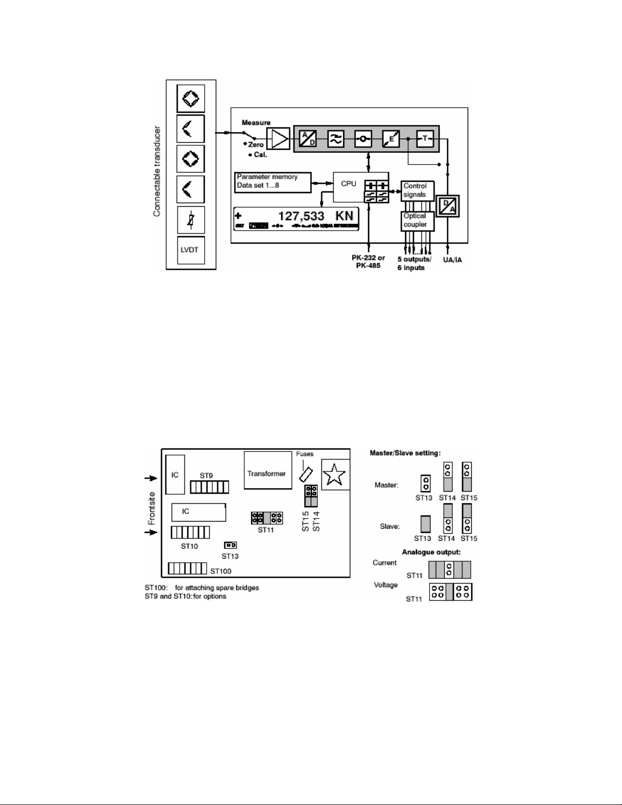
1.3 Block diagram
Fig. 1.1 DFI 2555 block diagram
2.0 MOUNTING
2.1 Pre-installation notes, factory settings
Before installing the device, check the parameters set at the factory, as the elements for selecting the analog output
signal (current/voltage output) and for setting synchronization, are located on the motherboard.
The factory settings are given below:
• Mains voltage: 230 V / 50 ... 60 Hz or 115 V / 50 ... 60 Hz, depending on order
• Analog output: output voltage ±10 V
• Synchronization: Master
Fig. 2.1: Location of jumpers on motherboard
2.2 Changing the factory settings
To change the factory settings, proceed as follows:
• Loosen the four screws at the back of the housing.
• Carefully extract the back panel of the housing backward, with the motherboard attached, until the jumper ar-
rangement is accessible. You can place a screwdriver between the connection board and the housing and lever
out the back panel.
• By following the diagram, change whichever setting is relevant to you with the aid of the jumpers.
CF 69 3 V-A0104-5.3 en
Page 6
2.2.1 Setting the analog output signal
To make the analog output signal setting (voltage or current), use jumpers ST11. Choose between ±20 mA or 4 ...
20 mA in the control dialogue.
2.2.2 Choosing the operating mode for synchronization
To synchronize several devices, set one device as the Master. All the other devices should then set to Slave. To
make the “Master” and “Slave” selections, use jumpers ST13, ST14 and ST15.
2.2.3 Replacing the fuses
To replace the fuse, remove the back panel of the housing as described. The fuse (230 V/100 mA; 115 V/200 mA)
will then be accessible on the motherboard (see Fig. 2.1).
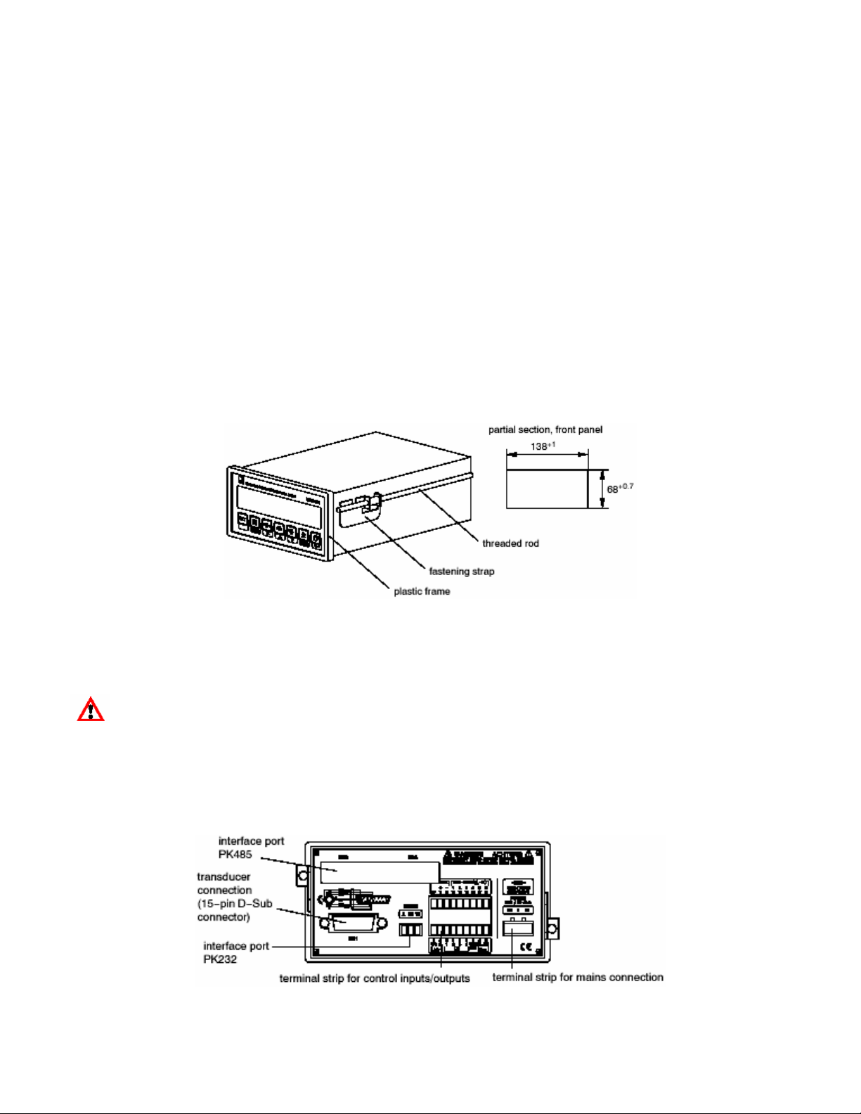
2.3 Installing the amplifier in a panel-frame
The DFI 2555 is designed to be installed in panel-frames, in accordance with DIN43700.
Installation steps:
• Remove the fastening strap.
• Insert the housing into the cutout in the panel-frame from the front.
• Hang up the fastening strap on both sides and fasten it to the cutout with the two threaded rods.
• Then connect the supply voltage and the transducer, as shown in chapter 3.
Fig. 2.2: Housing with fastening components
3.0 CONNECTIONS
CAUTION
Before commissioning the device, please observe the safety instructions.
3.1 Connecting the voltage supply
Check that the mains voltage of the device (details on the back of the device) matches the supply voltage. If this is
not the case, please contact Cooper Instruments.
Fig. 3.1 Back of the device
CF 69 4 V-A0104-5.3 en
Page 7
CAUTION
As the device does not have a separate power switch, do not connect the power cable directly to the
mains. According to the VDE guideline, there must be a switching device to disconnect the device from the
mains.
Connecting the mains cable:
• The cable must not be connected to the mains!
• Twist the wire ends of the mains cable and fit the end sleeves for strands
• Screw the wire ends to the terminal strip connector (3-pin)
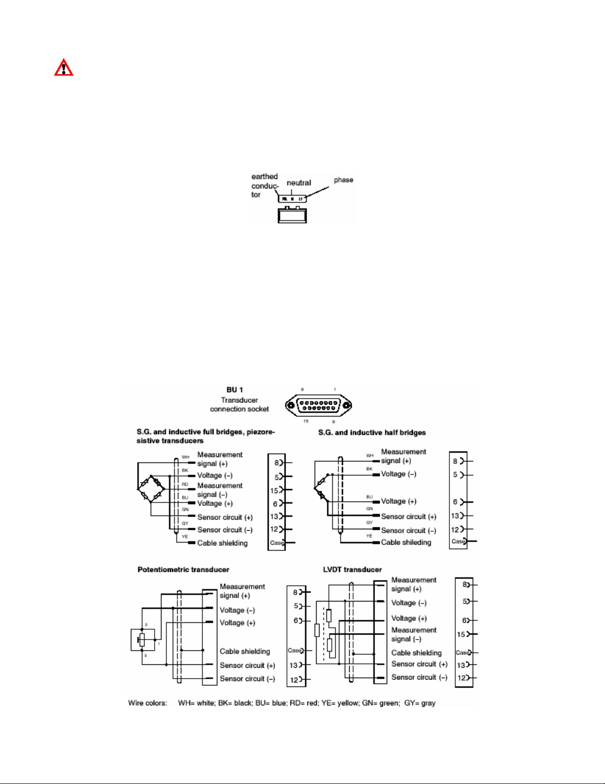
Fig. 3.2: Pin assignment of the terminal strip connector (3-pin)
• Plug the terminal strip connector (3-pin) into the mains connection socket
3.2 Connecting transducers
The following transducer types can be connected to the device:
• S.G. full and half bridge transducers
• Inductive full and half bridge transducers
• Potentiometric and piezoresistive transducers
• LVDT (Linear Variable Differential Transformer)
The connection is made using a 15-pin D-Sub connector on the back panel of the housing, labeled BU1 (cable end
connector: DB-15P).
Fig. 3.3: Connecting different transducers
CF 69 5 V-A0104-5.3 en
Page 8
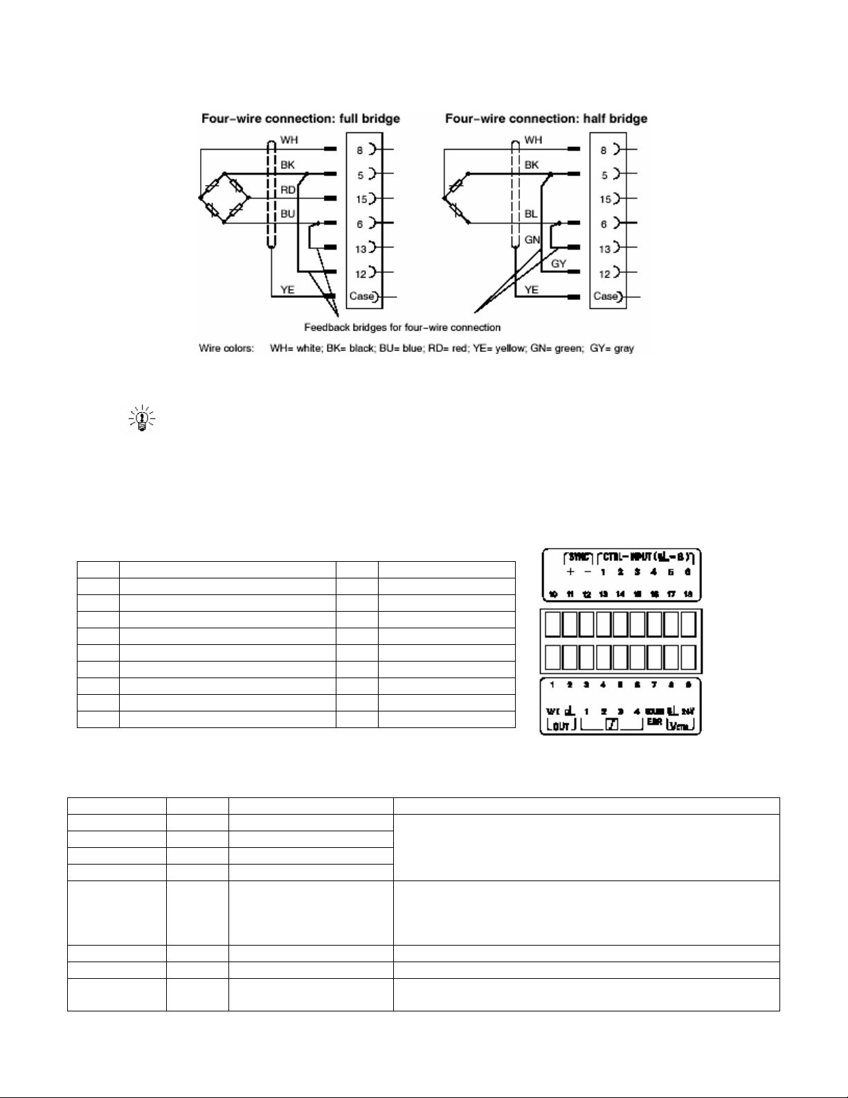
When connecting a transducer using four-wire technique, you must connect the sensor circuits with the relevant
bridge excitation circuit in the male cable connector (pin 5 with pin 12 and pin 6 with pin 13).
Fig. 3.4: Transducer connection in four-wire technique
NOTE:
To connect the transducers, use standard cable. If you use another shielded, low-capacitance
measurement cables, connect the shielding of the transducer cable to the connector housing, in accordance with HBM Greenline information (document G36.35.0). This guarantees EMC protection.
3.3 Analog output
The analog output signal is available as voltage (±10 V) or as current (±20 mA or 4 ... 20 mA) at terminals 1 and 2.
To choose current or voltage, use the jumpers on the amplifier motherboard, as described in Chapter 2.1.
Pin Function Pin Function
1 Output signal (V/I) 10 no function
2 Output signal (ground) 11 Synchronization (+)
3 LIMITVAL.1 12 Synchronization (-)
4 LIMITVAL.2 13 Remote1 (...)
5 LIMITVAL.3 14 Remote2 (...)
6 LIMITVAL.4 15 Remote3 (...)
7 Warning 16 Remote4 (...)
8 Ground 17 Remote5 (...)
9 External supply voltage 24 V= 18 Remote6 (...)
Fig. 3.5: Output pin assignment
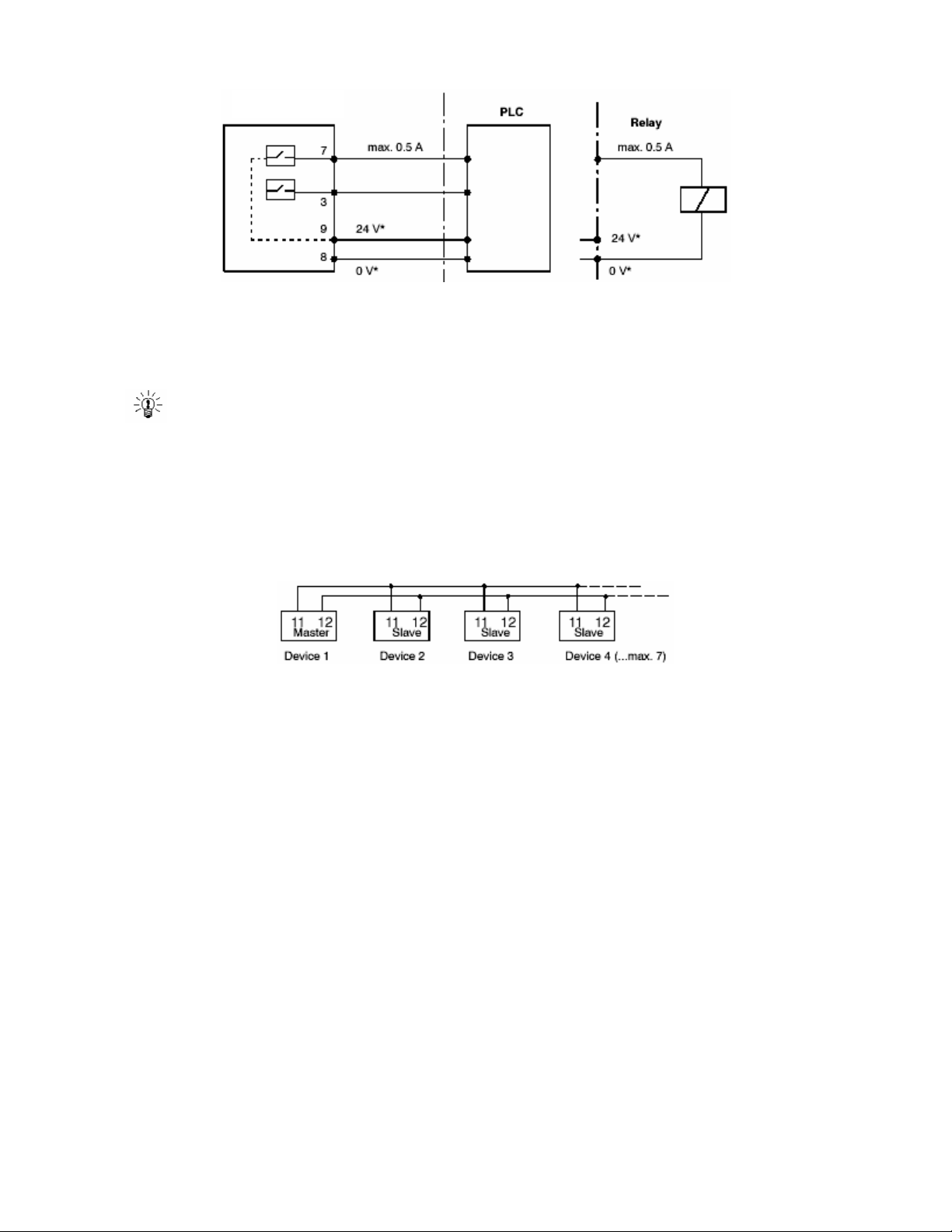
3.4 Control inputs / outputs
Input/Output Terminal Function
←
←
←
←
←
→
→
→
3 Output LIMITVAL. 1
4 Output LIMITVAL. 2
5 Output LIMITVAL. 3
6 Output LIMITVAL. 4
7 Output warning (overflow) Warning active in the case of overflow,
8 Ground V
9 External supply voltage V
13-17 Input remote 1-6 (function
selectable)
With positive logic equivalent to V
24 V
Autocal and MOTION OUT
24 V =OK
0 V = Warning
0 V
ext.
24 V
ext.
see table on Page 46
ext.
CF 69 6 V-A0104-5.3 en
Page 9
DFI 2555
Fig. 3.6: Output assignments
The control inputs and outputs are available at the terminal strip socket (9-pin) and are potential-separated by optical couplers.
* The control outputs and inputs must be supplied with an external voltage (ground and 24 V).
NOTE
When the mains voltage is disconnected or fails and when the mains fuse blows, all the control outputs are
set to 0 V (V
ext.
).
3.5 Synchronization
If several devices are used right next to one another or if their cables run parallel, the devices should be synchronized. To achieve this, one device is set to Master and all the others (max. seven) to Slave. The setup with jumpers
on the amplifier motherboard is described in Chapter 2.1. As well as these settings, the devices must be linked together for synchronization.
Fig. 3.7: Terminal connections for synchronization
3.6 Setting the reading angle of the display
Depending on the mounting position, it may be possible to adjust the reading angle. A potentiometer is used for this
limited adjustment. The potentiometer is located behind the keyboard under the display. To set a new viewing angle, proceed as follows:
• Remove the plastic frame of the display from the housing.
• Carefully lever out the keyboard (e.g. with the aid of a screwdriver).
• Use a screwdriver to turn the potentiometer and set the optimum reading angle.
• Put back the keyboard. Make sure that the plug is correctly threaded at the bottom edge of the keyboard.
Quickly test the keyboard by pressing a key. If it functions correctly, you can continue.
• Insert and tighten the fastening screws.
• Push the plastic frame back on the housing.
CF 69 7 V-A0104-5.3 en
Page 10
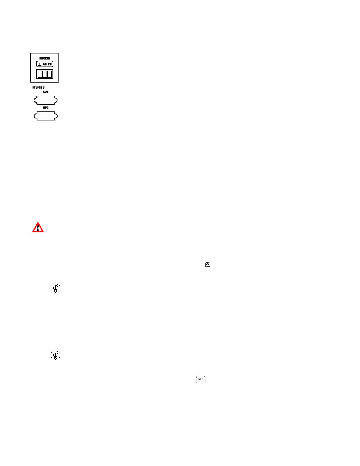
3.7 Connecting the serial interface
PK232-interface:
On the back of the device, there is an RS232 or RS485 serial interface for connecting a computer or
a terminal. The PK485-interface is brought out at sockets Bu2 and Bu3.
When connecting a printer, a simple line printer needing no more than 4 seconds to print a line is
sufficient. The printout has 12 columns. This corresponds to a line length of 132 characters. Select
the measured values to be printed as described in Chapter 4.4.11.
When connecting a computer, it is possible to enter into dialogue with the DFI 2555. You can use control commands to make all the device settings and query the measured values. An overview of the interface commands has
been compiled in another Operating Manual “DFI 2555 Serial Communications Guide”.
4.0 SETTING UP AND OPERATION
4.1 Commissioning and factory settings
Some of the steps you need to take to commission your measurement chain (panel-frame amplifier and transducer)
are listed below, so that you can carry out an initial function test of all components. The description basically covers
adapting the DFI 2555 to the transducer type to be used. We also warn about certain errors that can typically occur
during commissioning.
• Follow the steps given in the previous chapter to connect the mains cable and the transducer to the measuring
amplifier.
Please observe the safety instructions!
• Turn on the power switch.
• The device runs a function test and is then in measuring mode. Duration of the function test: 1.5 s (if auto-
calibration is enabled, approx. 2.5 s). During the function test, the warning output stays at 0 V. The factory
settings are active.
• Check the choice of output signal shown on the display. Use
display).
to select the gross signal (no labeling in the
NOTE
If the error message CALERR. appears here, this can have the following causes:
- No six-wire feedback connected
- Incorrect transducer/sensor connection
- No transducer/sensor connected
Remedy:
Switch off the device. Connect the transducer properly. Switch the device back on.
NOTE
If the error message “OVFL B, OVFL N,” appears, you must adjust the amplifier for your type of transducer. The
steps to take for each amplifier are described below.
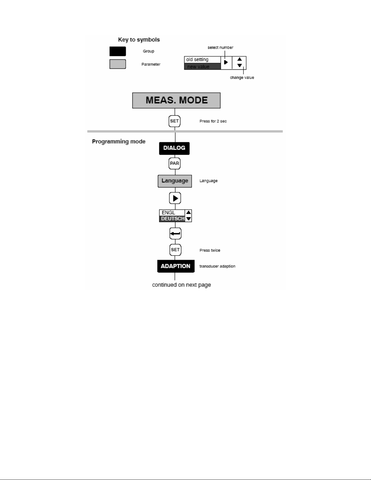
• To get from measuring mode to device setup mode, press
play.
• Follow the examples given below to adjust the device to the connected transducer type.
CF 69 8 V-A0104-5.3 en
for about 2 s. ”DIALOG” will appear in the dis-
Page 11

Transducer types:
S.G. force transducer:
Adaptation:
Example
Transducer type: Full bridge/2 mV/V=20 kN
Excitation: 2.5 V
Input: 4 mV/V
Calibration Unit, nominal value/decimal point 20.000 kN
Measuring range 2 mV/V
Inductive displacement transducer:
Adaptation:
Example
Transducer type: Half bridge, 10 mV/V
(80 mV/V)
Excitation: 1.0 V
Input: 10 mV/V (100 mV/V)
Calibration: Unit, nominal value/decimal point: 20.000 mm
Measuring range: 10 mV/V (80 mV/V)
Piezoresistive transducer:
Adaptation:
Example
Transducer type: Half bridge
Excitation: 2.5 V
Input: 400 mV/V
Calibration: Unit, nominal value/decimal point: 30.000 bar
Measuring range: 200 mV/V
Potentiometric transducer:
Adaptation:
Example
Transducer type: Half bridge
Excitation: 1 V
Input: 1000 mV/V
Calibration: Unit, nominal value/decimal point: 10.000 mm
Measuring range: 1000 mV/V
CF 69 9 V-A0104-5.3 en
Page 12
CF 69 10 V-A0104-5.3 en
Page 13

Continued at right…
Continued below…
CF 69 11 V-A0104-5.3 en
Page 14

The settings are saved in parameter set 1 and the device switches to measuring mode. You can now run an initial
function test.
NOTE
The settings are only stored power fail safe, if they were saved as one of the parameter sets.
4.2 Control concept and functional overview
The control concept makes a distinction between two types of button functions:
-Buttons that are operative during measuring mode
-Buttons needed for programming.
CF 69 12 V-A0104-5.3 en
Page 15

4.3 Button functions in measuring mode
Key Meaning
Switch from me assuring operating mode to programming (and vice versa) by pressing for approx. 2 s.
Set the limit values LV1 ... 4 (see 4.3.1)
The additional parameters of the limit switches such as hysteresis, direction etc., are unchanged. Limit
value changing can be enabled in menu LIMITVAL 1 ... 4. (see 4.5.6)
Zeroing the measurement chain (also possible by remote). The signal at the input is applied as the zero
point.
Taring the measured value (also possible by remote). The current measured value is applied as the tare
value in the tare buffer.
Deletes the contents of the peak value store (also possible by remote). This function applies to all peak
value stores (Min, Max, Peak-to-Peak).
Output of measured values or parameters over the interface (also possible by remote).
For possible print parameters, see ”Additional function” starting on Section 4.5.9.
Only those parameters (PRINT xxx) selected in additional functions will be printed.
Switches the measured value display between:
Gross value No labeling in the display
Net value (=gross minus tare) ”NET” is displayed
Minimum value
Maximum value “MAX” is displayed
Peak-to-peak value ”MAXMIN” is displayed
”MIN” is displayed
4.3.1 Querying and setting limit values in measuring mode
You have several options available when choosing the limit values (in measuring mode):
a: Numerical value entry for limit values
b: Apply input signal as limit value
c: Fast search (keep arrow keys pressed for several seconds)
CF 69 13 V-A0104-5.3 en
Page 16

4.4 Button functions in programming mode
In this operating mode, you can make all the settings for using the amplifier in your application. The parameters are
collected into groups.
Significance of the buttons:
Change operating mode, select group (e.g. CALIBR.)
Parameter selection (e.g. NOM. VALUE)
Display last value set.
Select desired number.
Changes the number in ascending order
Changes the number in descending order
Apply measured value
Confirms input/modification
4.4.1 Changing from ”Measuring” Operating Mode to ”Programming”
Press for 2 s
If the password is 0000 (factory setting), the device changes the operating mode.
If a password has already been entered (and is not 0000), CODE appears, that is, the password has to be entered if you wish to continue ”Programming”.
Enter password:
press twice
Enter password (four-figure number)
If you enter an incorrect password, the device goes back to measuring mode. If the password matches, the
DIALOG group appears in the display.
4.4.2 Programming
Typical programming mode operations
Select the value/parameter from a given ta-
ble (example DIALOGUE LANGUAGE)
Enter a numerical value as a parameter (example CALIBR./RANGE)
Apply a signal produced by the transducer when a defined loading occurs.
*Only possible when setting the zero value, the measuring range and the limit values
CF 69 14 V-A0104-5.3 en
Page 17

4.4.3 Switching from ”Programming” Mode to ”Measuring”
When the parameters are changed, you are asked whether the modified parameters are to be saved power fail
safe.
NOTE
The settings are only stored power fail safe, if they were saved as one of the parameter sets.
4.5 Overview of all groups and parameters
PARAM BUTT.TARE FILTER ZERO VALUE HYSTERESIS SET CONTACT 2 STOPBITS
↓ BUTT.PVS MOTION CNT RANGE LOGIC CONTACT 3 COMM.ADDR
DIALOG
LANGUAGE RECALL TRANSDUCER UNIT ENABLE ENABLE SOURCE UA P34
PASSWORD SAVE? EXCITATION NOM. VALUE SOURCE PVS1 MODE UA SERIAL NO.
BUTT.LVS SET INPUT DEC.POINT SWITCH DIR. PVS2 INPUT SIGN. BAUDRATE
↓
BUTT.ZERO AUTOCAL STEP LEVEL ENVELOPE CONTACT 1 PARITY
BUTT.PRINT MOTION DIG TARE VALUE LV BUTT CONTACT 4 PRINT GROSS
BUTT.SIGN MOTION OUT SET SET CONTACT 5 PRINT NET
SET1) SET CONTACT 6 PRINT MAX
Parameter
1)
Use to next group
PARAM.
SET
ADAPTATION CALIBR.
→
Groups
LIMITVAL.
1 … 4
PV STORE IN/OUT ADD. FUNCT.
REMOTE PRINT MIN
SET PRINT PP
PRINT LVS
PRINT OVERL
PRINT PAR.
ZERO/TARE
SET
CF 69 15 V-A0104-5.3 en
Page 18

4.5.1 Setting all parameters
CF 69 16 V-A0104-5.3 en
Page 19

CF 69 17 V-A0104-5.3 en
Page 20

CF 69 18 V-A0104-5.3 en
Page 21

4.5.2 Dialogue
Select language (LANGUAGE)
Factory setting: DEUTSCH
You can choose the following languages:
German (DEUTSCH), English (ENGLISH), French (FRANCAIS), Italian (ITALIANO), Spanish (ESPANOL)
Choose password (PASSWORD)
When switching from Measuring to Programming, you are asked for a password (see 4.4.1). The password pre-
vents unauthorized operation of the DFI 2555. Parameters can only be changed if the valid password is entered.
The password can only be changed if the old password is known.
CODE Function
0000 no password; factory setting
0001 ... 9999 password set
Enable/lock buttons
BUTT. LVS :
BUTT. ZERO:
BUTT. TARE:
BUTT. PVS:
BUTT. PRINT:
BUTT. SIGN :
Factory setting: ENABLED
Factory setting: ENABLED
Factory setting: ENABLED
Factory setting: ENABLED
Factory setting: ENABLED
Factory setting: ENABLED
4.5.3 Load/Save in parameter set (PARAM. SET)
The current device amplifier settings can be saved power fail safe in eight parameter sets and later queried. When
switching from the programming operating mode to measuring mode, you will be asked whether or not the change
is to be saved. This is described in Chapter 4.4.3.
You can also use remotes (PARACODE1 ... 2, see Chapter 4.5.8) to Activate/Load parameter sets.
RECALL: Parameter set 1 (parameter set 1 ... 8) and the factory setting (FACT. SETUP) are loaded
SAVE: Save as parameter set 1 ... 8
4.5.4 Adaptation
TRANSDUCER:
Depending on the type of transducer, you can choose between the following bridge types:
Selectable bridge types
EXCITATION:
The excitation voltage for the transducer is selected.
Selectable excitation voltages
INPUT:
Depending on which excitation voltage is chosen, the input range (approximate measuring range) can be selected
for the transducer type.
Input range
I
II
III
1) No distinction is made here between transducers with strain gauges and inductive transducers.
Full bridge
UB = 2.5 V UB = 1 V
±4 mV/V ±10 mV/V
±40 mV/V ±100 mV/V
±400 mV/V ±1000 mV/V
1) Half bridge 1) LVDT
1 V 2.5 V
CF 69 19 V-A0104-5.3 en
Page 22

AUTOCAL:
Depending on the application and on the stability requirement, you can start an autocalibration cycle. This lets you
correct zero point and full scale value drift and the long-term constancy of the measuring amplifier.
Possible settings:
ON
OFF
ONCE
Autocalibration is run once, as soon as you confirm it with . Autocalibration stays on/off, depending
Autocalibration switched on
Autocalibration switched off
on the state previously selected.
CAUTION
If you need the analog output signal for continuous monitoring, you must switch autocalibration off. Reason: during the autocalibration cycle, no measured values are recorded. This produces a “monitoring gap”
(interval approx. 5 min., duration approx. 1 s), which is undesirable if not dangerous during production
processes.
FILTER:
Different filter cutoff frequencies and the filter characteristics can be selected:
Bessel (BE)
(Hz)
Sampling rate
(measured values per sec)
2)
Butterworth (BU)
(Hz)
Sampling rate2)
(measured values per sec)
0.05 18.75 5.0 1200
0.1 37.5 10 1200
0.2 75 20 1200
0.5 300 40 1200
1.25 600 80 1200
2.5 1200 200 1200
5.0 1200
10 1200
20 1200
40 1200
100 1200
200 1200
2) See Motion count (MOTION CNT)
MOTION CNT (Motion count)
To activate the motion count, you must set the number of measurements. During these measurements, the measured value must fall within the given tolerance for ”standstill” to be reported. (for sampling rate, see table).
Settings
+255 MEAS Maximum possible number of measurements
MOTION DIG
Input of tolerance field in digits in display units.
000110 kN
MOTION OUT
Output of motion count status (control output terminal 7; warning).
Possible settings:
+000 MEAS Motion count switched off
OFF The motion count status is not output over WARNING
ON WARNING active, if no standstill or device error
CF 69 20 V-A0104-5.3 en
Page 23

Fig. 4.1: Effect of the motion count
4.5.5 Calibration (CALIBR.)
UNIT
You can select the following units:
Selectable unit
N S cm
OZ PPM mm
LB % µm
TON % PSI
KT M/SS KPAS
T M/S HPAS
KG µm/m PAS
G INLB PA
V FTLB mBAR
mV/V KNm BAR
MP INCH KN
---- m A
mA
NOM. VALUE
You can adjust the nominal value. Specify the nominal value including the desired decimal places.
Examples:
a. You want to measure in a pressure range between 0 and 1000.00 bar:
Enter nominal value: 100000
b. With a 50 kg load cell, you want to display the measured value with 3 decimal places.
Enter nominal value: 50000
DEC. POINT
Changes the position of the decimal point.
Selectable positions
For above example a: .00
For above example B: .000
STEP
You can choose the step or the digit step.
Selectable steps
ZERO VALUE
The maximum zero balance range matches the particular maximum measuring range in the following table.
.0000 0.000 00.00 000.0 0000
1 2 5 10 20 50 100 200 500 1000
CF 69 21 V-A0104-5.3 en
Page 24

RANGE:
Sets a full scale value (unit mV/V). If this value lies outside the input range, the minimum or maximum possible
value is accepted.
Input range Measuring range at UB = 2.5 V Measuring range at UB = 1 V
I ± 0.2 ... 4 mV/V ± 0.5 ... 10 mV/V
II ± 2 ... 40 mV/V ± 5 ... 100 mV/V
III ± 20 ... 400 mV/V ± 50 ... 1000 mV/V
When the measuring range is set, an analog output signal is allocated to the input signal range.
TARE VALUE:
You can specify a tare value (in display units) (net value = gross value minus tare value).
4.5.6 Limit switches 1 ... 4 (LIMITVAL.1 ... 4)
The parameters for setting the limit switches are collected in a group for each limit value. The status of the limit
switches is shown on the display and carried out over the control outputs. The function of the limit switches and
their parameters are shown in the following diagram:
Fig. 4.2: Limit switch functions and parameters
ENABLE
OFF
ON
SOURCE
Limit switch evaluated:
GROSS.VALUE
NET VALUE
PVS1 MAX
PVS2 MIN
PVS3 PP
SWITCH DIR.
Specify here the switch direction or the working direction (see Fig. 4.2.).
HIGHER
LOWER
LEVEL
The level is set in display units (e.g. 2,000 kN).
HYSTERESIS
The hysteresis value prevents “fluttering” of the limit switches upon reaching the switching threshold. Hysteresis results from the difference between the activation and deactivation threshold.
The value is set in display units (e.g. 2 kN).
LOGIC
You can change the output logic of the remotes as required. The following allocation was made:
Disable individual limit switches
Enable individual limit switches
Gross
Net
Store for maximum values
Store for minimum values
Store for peak-to-peak value
The switch-on level is higher than the switch-off level for a rising measured value
The switch-off level is higher than the switch-on level for a falling measured value
CF 69 22 V-A0104-5.3 en
Page 25

ACTIVE.HIGH
Switched on = High
Switched off = Low
ACTIVE.LOW
Switched off = High
Switched on = Low
LV BUTT:
ENABLED
LOCKED
Setting the limit value with possible
Setting the limit value with locked
4.5.7 Set peak value store (PV STORE)
Two peak value stores are available to you for monitoring processes. The following allocation has been made:
PVS1
PVS2
Store for maximum values
Store for minimum values
Use
key to display the Min/Max values in Measure mode.
An additional value is determined arithmetically.
PVS3
Store for peak-to-peak value
Linking with PVS1 regarding control functions and envelope.
Both can be operated as peak value stores or as instantaneous value stores. The choice of operating mode is
made with the remotes.
PVS1 INST
PVS1/Hold
PVS2 INST
PVS2/Hold
Instantaneous or peak value for PV1/PV3
Run / Hold mode for PV1/PV3
Instantaneous or peak value for PV2
Run / Hold mode for PV2
The following diagram shows the function of the remotes:
Fig. 4.3: Function of the remotes shown in the example of PVS1, peak value and instantaneous value stor-
age (also applies to PVS2 and PVS3).
If the stores are operated as peak value stores, it is possible to display an envelope by setting a discharge rate.
This discharge rate affects all peak value stores.
CF 69 23 V-A0104-5.3 en
Page 26

Fig. 4.4: Envelope function
You can set the following parameters:
ENABLE:
You can enable or lock the peak value stores.
PVS ON
PVS OFF
PVS1 INPUT:
Choice of input signal for peak value store PV1.
GROSS.VALUE NET VALUE
PVS2 INPUT:
Choice of input signal for peak value store PV2.
GROSS.VALUE NET VALUE
ENVELOPE:
You can choose the discharge rate (time constant of the discharge function) of the envelope function for both the
peak value stores. The specification corresponds to a time in s.
000.00
000.100 to 60.000 s
4.5.8 Inputs and outputs (IN/OUT)
In this menu, you can make the required settings for the DFI 2555 input signal, the analog output and the remotes.
SOURCE UA:
The following signals can be specified as the source of the analog signal:
GROSS.VALUE
NET VALUE
PVS1 MAX
PVS2 MIN
PVS3 PP
MODE UA:
Depending on the analog signal you select, the following options are possible:
Display Meaning
UA OFF 0 TO 20mA output ± 20 mA
4 TO 20MA output +4 ... 20 mA
UA OFF -
10 VOLT output ±10 V
Enable peak value store
Peak value store locked
envelope function off
envelope function on
Gross
Net
Store for maximum values
Store for minimum values
Store for peak-to-peak value
NOTE
The current output or voltage output selection is made using jumpers on the amplifier motherboard.
CF 69 24 V-A0104-5.3 en
Page 27

INPUT SIGN.:
For test purposes, a calibration signal and a zero signal can be displayed instead of the measurement signal. You
can choose the following input signals:
MEAS.SIGNAL
CAL SIGNAL3)
ZEROSIGNAL3)
3)
To display the measurement signal, you must return to measuring mode.
The display corresponds to 50 % of the current full scale value
Measuring mode
Internal zero point
CONTACT 1 ... 6:
Remotes are available on the connector strip for controlling DFI 2555 functions. The pin assignment or allocation of
the remotes is freely configurable.
Functions Level 0 V Level 24 V
NO FUNCT. No function (factory setting)
AUTOCAL Autocalibration ON Autocalibration OFF
TARE For the transition 0 V – 24 V, the tare value is adopted
PVS1 INST Peak value operating mode for PV1 Instantaneous value operating mode for PV1
PVS1/HOLD Store contents PV1 and PV3 are updated Store contents PV1 and PV3 are frozen
PVS2 INST Peak value operating mode for PV2 Instantaneous value operating mode for PV2
PVS2/HOLD Store contents PV2 are updated Store contents PV2 are frozen
ZEROING For the transition 0 V – 24 V, the current instantaneous input signal is adopted as the zero value
PRINT A printout is triggered over the interface
GROSS/NET Gross at analog output Net at analog output
PARACODE 1
PARACODE 2
External selection of parameter sets and binary coded inputs
(see following table)
PARACODE 3
BUTT.LOCK Enabled Locked
PARAM. SET
PARACODE
3 2 1
1 0 0 0
2 0 0 1
3 0 1 0
4 0 1 1
5 1 0 0
6 1 0 1
7 1 1 0
8 1 1 1
REMOTE
Device control through remotes can be locked or enabled.
ON
OFF
display
No display Operating using keyboard and remotes
LOCAL Keyboard operation only
4.5.9 Additional functions (ADD. FUNCT)
P_ _:
In order to provide better support should you experience technical problems, the firmware status is indicated by this
parameter. If you have any questions for our service department, giving the existing firmware version will enable us
to provide effective support.
Example: P34 Software version P34
SERIAL NO.:
Display the serial number of the device.
Baud rate:
Choose the baud rate to match the baud rate of the connected device (PC, PLC).
Selectable baud rates
300 600 1200 2400 4800 9600
CF 69 25 V-A0104-5.3 en
Page 28

PARITY:
The following settings are possible:
Selectable parity
EVEN PAR. ODD PAR. NO PAR.
Stop bit:
The following settings are possible:
1 STOPBIT
2 STOPBIT
COMM. ADDR:
Input the device address
Selectable device addresses
4)
Address selectable only for RS485 version; for RS232, set address to 1
4)
00 to 31
PRINT GROSS:
Output the gross value over the serial interface:
OFF/ON
Print NET:
Output the net value over the serial interface:
OFF/ON
Print MAX:
Output the maximum value over the serial interface:
OFF/ON
Print MIN:
Output the minimum value over the serial interface:
OFF/ON
PRINT PP:
Output the MIN/MAX value over the serial interface:
OFF/ON
PRINT LVS:
Output limit switch states over serial interface:
OFF/ON
PRINT OVERL
Adjust repetition rate. Heading comprising the source of the measured value and the unit.
0 = no heading (measured value only)
1 = Heading always
10 = Heading every 10 times etc.
Print PAR:
Output all the parameters:
START
NOTE
The chosen print functions (apart from PRINT PAR) are run in measuring mode (by pressing
or by re-
mote contact).
ZERO/TARE:
A change to the tare value or zero value by using the buttons
or is automatically stored in the current pa-
rameter set (EEPROM) power fail safe.
CF 69 26 V-A0104-5.3 en
Page 29

This backup can be switched on or off:
SAVE OFF
SAVE ON
NOTE: The EEPROM is restricted to approx. 10000 write cycles.
5.0 EXAMPLE
The following example uses a measurement task to show you the functionality of the device and the required settings.
Problem definition:
The forming process in a press is to be monitored in order to obtain uniform product quality. The maximum force
exerted by the press is to be recorded in each cycle. To guarantee the production process, this maximum force
must fall between the lower (F1) and upper (F2) force limit.
Solution:
The force characteristic measured with an S.G. force transducer (e.g. C9B/10 kN; 1 mV/V) is amplified and evaluated by the DFI 2555. The peak value store (maximum) is used to record the maximum force and it is evaluated
with two limit switches with regard to the lower and upper limits. An additional limit switch is provided for overload
protection (emergency shut down) of the machine.
A PLC takes over the control of the process. As well as the control commands for the press, it gives the DFI 2555 a
start signal to begin the pressing cycle and once the process has finished, logically links the limit switch outputs to
the ”Good/Bad evaluation”.
The start signal from the PLC clears the contents of the peak value store through the DFI 2555 control input. To
prevent unintentional modifications, during measurement, only the ”Display signal selection” button is enabled for
the machine operator on site.
The parameter setups are protected against unauthorized modification by a password.
Device control through the remotes (remote control) must be activated.
Wiring diagram:
DFI 2555
CF 69 27 V-A0104-5.3 en
Page 30

Time chart:
Evaluation of limit value message by the PLC:
Good Reject
LV1 1 0 1
LV2 1 1 0
Choose the following settings:
LV1 Checks whether the lower force limit has been reached. The input signal is the output of the peak value
store (maximum value). If limit LV1 is exceeded, a High signal is generated. A positive switch direction
must be set with positive output logic.
Limit2 Checks whether the upper force limit has been reached. The input signal is the output of the peak value
store (maximum value). If limit LV2 is exceeded, a Low signal is generated. A positive switch direction
must be set with positive output logic.
LV3 Checks whether the maximum load limit of the machine is exceeded (emergency shutdown function).
The input signal is the gross measured value. If limit LV3 is exceeded, a High signal is generated. A
positive switch direction must be set with positive output logic.
PVS1 Records the maximum peak value of the force characteristic. Must be enabled, the envelope function
must be deactivated. The input signal is the gross measured value. PVS1 is cleared with remote 1 by
switching to instantaneous value.
Remote 1 Clears the contents of the peak value store. The function PVS1 INST must be selected. Remote con-
trol must be activated.
ADA
CF 69 28 V-A0104-5.3 en
Page 31

Continued at right
CF 69 29 V-A0104-5.3 en
Page 32

PTATION
Continued at right
CF 69 30 V-A0104-5.3 en
Continued on next page
Page 33

Continued at right
CF 69 31 V-A0104-5.3 en
Page 34

6.0 ERROR MESSAGES
Error message Cause Remedy
FIX The given value cannot be altered. Example: For unit
V and mV/V, the nominal value setting is fixed at 10,000
OVFL B Gross value overflow
OVFL N Net value overflow
CAL.ERR Incorrect transducer/sensor connection:
No transducer/sensor connected
No six-wire feedback connected
Connect the transducer properly.
Switch device off and then back on
again.
Measuring bridge connected incorrectly (e.g. full bridge
set, but half bridge connected)
HIGHER The value chosen for measuring range, zero point
value, nominal value or tare value cannot be set, as it
exceeds the permissible limits.
The device sets the maximum or
minimum value automatically, as
soon as the error message has been
acknowledged by “ENTER”
DATA ERROR. A transmission error occurred when
saving the parameters
7.0 SPECIFICATIONS
Type DFI 2555
Accuracy class 0.1
Mains connection/supply voltage
Power Consumption, max.
Safety fuse (slow blowing)
Amplifier
Carrier frequency
Excitation voltage U
(±5%)
B
Connectable transducers
S.G. half and full bridge
Inductive half and full bridge,
LVDT’s
Permissible cable length between transducer and
amplifier
Measurement frequency range,
adjustable 9-1 dB)
Input level
Measuring range UB=2.5 V
U
=1 V
B
Bridge balance range
=2.5 V
U
B
U
=1 V
B
Noise voltage1) 0…200 Hz
0…1.25 Hz
Effect of 10K change1) in ambient temperature
(Autocalibration on / off)
Sensitivity
Zero Point
1) For UB =2.5 V, relative to the input
V
Hz
VA
mA
Hz
Vrms
Ω
mH
m
Hz
mV/V
mV/V
mV/V
mV/V
µV/V
µV/V
%
µV/V
PP
PP
115/230, +6%; -10%;
48…60
8
200 (115 V) / 100 (230 V)
4800 ± 0.32
1 or 2.5
UB =1 V
40…5000
6…19
max. 500
rms
UB =2.5 V
rms
80…5000
2.5…20
max. 500
0.05…200
low medium high
0.2…4
0.5…10
±4
±10
0.5
0.015
0.04/0.1
0.2/2
2…40
5…100
±40
±100
1
0.1
0.04/0.1
2/20
20…400
50…1000
±400
±1000
10
1
0.04/0.1
20/200
CF 69 32 V-A0104-5.3 en
Page 35

Measurement frequency range
Butterworth low-pass
Bessel low-pass
Nom.
val fc
(Hz)
Nom.
val fc
(Hz)
1.25
0.05
500
200
80
40
20
10
400
200
100
40
20
10
2.5
0.5
0.2
0.1
5
5
-1 dB
(Hz)
485
245
78
38
19
9.1
4.6
-1 dB
(Hz)
400
215
111
39
21
11
5.3
2.7
1.4
0.7
0.17
0.09
0.044
-3 dB
(Hz)
580
290
98
50
26
12.5
6.3
-3 dB
(Hz)
750
395
190
68
37
19
9.7
4.9
2.4
1.2
0.3
0.16
0.075
Run
Time
(ms)
1.1
1.7
4.3
7.1
12
22
41
Run
Time
(ms)
0.8
1.3
2.5
8.1
14
25
48
90
180
700
1400
2900
5
Rise
Time
(ms)
0.7
1.3
3.8
7.3
14
28
56
Rise
Time
(ms)
0.6
1.0
2.1
5.5
10
19
38
75
150
300
1200
2300
4700
Overshoot.
about
10%
12
11
10
8
7
6
5
Overshoot
about
10%
2
2
2.5
1.1
1
0.7
0.3
0
0
0
0
0
0
CF 69 33 V-A0104-5.3 en
Page 36

Max. permissible common-mode voltage
Common-mode rejection
Max. differential voltage DC
Linearity variation
Long-term drift over 48 hours,
Meas. range 2 mV/V
30 minutes after switching on
(warm-up time)
Analogue output
Applied voltage
Permissible load resistance, min.
internal resistance, max.
Impressed current
Permissible load resistance, max.
internal resistance, min.
The analogue output can show gross, net, positive
and negative peaks and peak/peak values
V
DB
V
%
µV/V
V
kΩ
Ω
mA
Ω
kΩ
± 5 V
typically 110
± 10 V
typically 0.05
Autocalibration on/off
<0.2/ <0.4
± 10 V (asymmetric)
5
1.5
± 20; 4…20
500
100
Interference voltage at the output, typ.
Residual carrier voltage 38.4 kHz
Residual carrier voltage 4800 Hz
Long-term drift (over 48 h)
(30 minutes after switching on)
Effect of 10K change in ambient temperature (ad-
ditional effect to digital value)
Zero point
Sensitivity
Limit switches
Number
Reference level
Reference excit. (independently adjustable)
Factory settings, hysteresis
Adjustment accuracy
Response time
Peak value stores
Number
Function
Update rate
Clearing the peak value store.
Recording the current value/peak value
Time constant for envelopes
mV
PP
mV
PP
mVPP
mV
mV
%
V
V
V
mV
ms
ms
ms
ms
ms
4
3
2
< 3
< 3
< 0.05
4
Gross, net, peak values
-10…+10
0.1
0.33
0.83
(All Butterworth filter frequencies and Bes-
sel filters >1.25 Hz. The values double
each time for the next lower measurement
frequency)
2
Positive; negative; peak-to-peak
0.03
(with Butterworth filter and
Bessel filter >100 Hz)
3.3 (Remote contacts)
3.3 (Remote contacts)
100…60 000 (±6%)
CF 69 34 V-A0104-5.3 en
Page 37

Control outputs (limit switch 1…4,
Warning V
CTRL
)
Nominal voltage, external power supply
Permissible supply voltage range
Output current, max.
Short-circuit current, typ.
Short-circuit period
Isolation voltage, typ.
Remote contacts
Input voltage range, LOW
Input voltage range, HIGH
Input current, typ., HIGH level = 24 V
Interface
Measuring rate, ASCII output
Binary output
Number of data bits
Baud rate
Parity
Stop bit
Parameter Memory (EEPROM)
Display
Number of points
Character height
Type
Keyboard
Dialogue languages
Effect of operating voltage in the case of changes
in the specified range, relative to the full scale
On zero point
On sensitivity
Nominal temperature range
Operating temperature range
Storage temperature range
Degree of protection,
under DIN IEC 60 529
Protection class
Dimensions, over everything (WxHxD)
Front panel frame dimensions
Front panel display section
(according to DIN 43 700)
1)
default settings
Weight, approx.
V
V
A
A
Vrms
V
V
mA
Meas.
/s
Bit
Baud
300,600,1200,2400,4800,9600
odd, even and no
24
11…30
0.5
0.8
unlimited
350
0…5
10…24
12
Approx. 25
Approx. 50
8
1)
1
; 2
1)
8 (parameter sets)
mm
(16-segment, plus var. special characters)
±10
12.5
LCD
(inverse with LED background lighting)
Touch-sensitive keypad with 7 deposited button elements on the printed circuit board Ger-
man/English/French/Italian/Spanish
%
%
°C
°C
°C
mm
mm
mm
kg
IP40 (device) IP51
(front, touch-sensitive keypad)
153x72x212 (220)
0.01
0.01
-20…+45
-20…+45
-20…+70
I
144x72
138x68
1
CF 69 35 V-A0104-5.3 en
Page 38

8.0 WARRANTY REPAIR POLICY
Limited Warranty On Products
Any Cooper Instruments product which, under normal operating conditions, proves defective in material or in workmanship within one year of the date of shipment by Cooper will be repaired or replaced free of charge provided that
a return material authorization is obtained from Cooper and the defective product is sent, transportation charges
prepaid, with notice of the defect, and it is established that the product has been properly installed, maintained, and
operated within the limits of rated and normal usage. Replacement or repaired product will be shipped F.O.B. from
our plant. The terms of this warranty do not extend to any product or part thereof which, under normal usage, has
an inherently shorter useful life than one year. The replacement warranty detailed here is the buyer’s exclusive
remedy, and will satisfy all obligations of Cooper whether based on contract, negligence, or otherwise. Cooper is
not responsible for any incidental or consequential loss or damage which might result from a failure of any and all
other warranties, express or implied, including implied warranty of merchantability or fitness for particular purpose.
Any unauthorized disassembly or attempt to repair voids this warranty.
Obtaining Service Under Warranty
Advance authorization is required prior to the return to Cooper Instruments. Before returning the item, contact the
Repair Department c/o Cooper Instruments at (540) 349-4746 for a Return Material Authorization number. Shipment to Cooper shall be at buyer’s expense and repaired or replacement items will be shipped F.O.B. from our
plant in Warrenton, Virginia. Non-verified problems or defects may be subject to a $100 evaluation charge. Please
return the original calibration data with the unit.
Repair Warranty
All repairs of Cooper products are warranted for a period of 90 days from date of shipment. This warranty applies
only to those items that were found defective and repaired; it does not apply to products in which no defect was
found and returned as is or merely recalibrated. It may be possible for out-of-warranty products to be returned to
the exact original specifications or dimensions.
* Technical description of the defect: In order to properly repair a product, it is absolutely necessary for Cooper to
receive information specifying the reason the product is being returned. Specific test data, written observations on
the failure and the specific corrective action you require are needed.
CF 69 36 V-A0104-5.3 en
 Loading...