

Page 1

DFI 2555 SERIAL
COMMUNICATIONS GUIDE
www.cooperinstruments.com
PH: (540) 349-4746 • FAX: (540) 347-4755
Page 2

CONTENTS
SAFETY INSTRUCTIONS............................................................................................................1
1.0 INTRODUCTION TO OPERATION WITH COMPUTER OR TERMINAL...............................1
2.0 SERIAL INTERFACE: RS-232C OR RS-485.........................................................................1
2.1 Introduction to the Interface ..........................................................................................................1
2.2 Key data for the serial interface.....................................................................................................2
3.0 COMMUNICATION WITH THE DFI 2555 ..............................................................................2
3.1 Connect DFI 2555 and computer ...................................................................................................2
3.2 Activation of the RS232C or RS485 interface...............................................................................3
4.0 COMMAND SET OF THE INTERPRETER ............................................................................3
4.1 Important conventions ...................................................................................................................3
4.1.1 Command structure .................................................................................................................4
4.1.2 Data-output Structure ..............................................................................................................4
4.2 Description of Individual Commands............................................................................................5
4.2.1 Setting-up of functions in the additional functions group ................................................... 6
4.2.1.1 Setting of the RS232C interface parameters.......................................................................6
4.2.1.2 Setting of the RS485 interface parameters .........................................................................7
4.2.1.3 Querying for Device Identification/Firmware Status. ...........................................................8
4.2.1.4 Print functions .....................................................................................................................8
4.2.2 Setting-up of the Parameter-sets group................................................................................. 9
4.2.3 Define output format, measurement output ........................................................................11
4.2.3.1 Define output format.......................................................................................................... 11
4.2.3.2 Specify measurement output.............................................................................................12
4.2.4 Setting up the Adaptation group functions ......................................................................... 13
4.2.4.1 Setting up amplifier input................................................................................................... 13
4.2.4.2 Choose filter settings......................................................................................................... 14
4.2.4.3 Setting autocalibration....................................................................................................... 16
4.2.5 Setting up the Calibration group functions ......................................................................... 17
4.2.5.1 Selecting the unit of measure............................................................................................ 17
4.2.5.2 Selecting the indication upper limit....................................................................................18
4.2.5.3 Setting zero value..............................................................................................................19
4.2.5.4 Set measuring range.........................................................................................................19
4.2.5.5 Tare...................................................................................................................................20
4.2.6 Setting up the Limit Value 1...4 group functions.................................................................20
4.2.7 Setting up the functions of the Peak value store group.....................................................22
4.2.8 Setting up the functions of the Inputs/Outputs group........................................................ 23
4.2.8.1 Select amplifier input signal...............................................................................................23
4.2.8.2 Setting up the analog output .............................................................................................24
4.2.8.3 Setting up remote control ..................................................................................................25
4.2.8.4 Setting up assignment of the remotes............................................................................... 25
4.2.9 Setting up the Adaptation group functions ......................................................................... 26
4.2.9.1 Lock-control of the keys .................................................................................................... 26
5.0 ABBREVIATION/COMMAND INDEX ..................................................................................27
CF 127 iii V. -A0109-5.3 en
Page 3
SAFETY INSTRUCTIONS
The instrument complies with the safety requirements of DIN EN 61010, Part 1 (VDE 0411, Part 1); Protection
Class I. When connecting the instrument please adhere to the factory-set main voltage. This is shown on the rear
panel of the housing (230V/115V, 48...60Hz). Since the instrument is not fitted with its own mains switch, the power
cable must not be connected direct to the mains supply. According to VDE Guidelines it must be possible to
disconnect these instruments from the mains by means of a switching device (e.g. a mains switch).
1.0 INTRODUCTION TO OPERATION WITH COMPUTER OR TERMINAL
The DFI 2555 panel amplifier for panel-frame mounting (in accordance with DIN 43700) is suitable for recording
and processing measured data from passive transducers in the field of industrial test-facility engineering and
manufacturing-process monitoring.
Its main features are:
• Attachable transducers: SG full and half bridges, inductive full and half bridges, piezoresistive transducers,
LVDTs, potentiometers
• 10-character alphanumeric display
• Operation through touch-sensitive keypad; keys individually lockable
• 2 peak value stores for maximum and minimum values, also envelope and instantaneous value
• 4 limit monitors
• Parameter store for storing up to 8 data records
• Control I/Os (optocoupler-isolated)
This manual describes how to operate your DFI 2555 with a terminal or computer. It describes connection of a
computer via the RS232 for complete parameter input and scanning of measured data.
All steps required for setting up the instrument via the keypad, all information required for commissioning and all
menus are listed and described in a separate document, ”DFI 2555 User’s Guide”.
2.0 SERIAL INTERFACE: RS-232C OR RS-485
2.1 Introduction to the Interface
Through this serial interface data is transferred serially, one bit at a time. General properties are:
• Transmission speed relatively ”low”
• Requires in the simplest case a 3-core cable for bi-directional (duplex) transmission
• Only one device can be connected (point-to-point link)
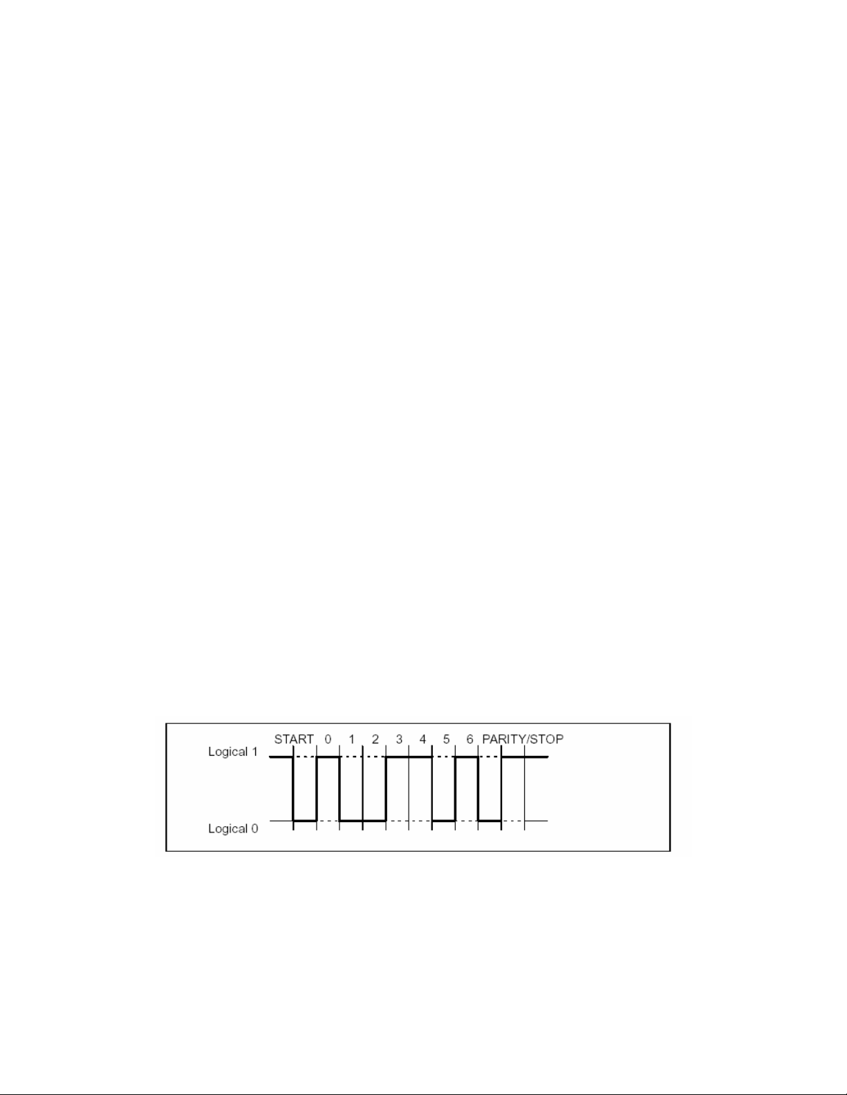
Figure 1:Line level of the character Y with negative logic
A start bit is placed in front of each character (data byte). Then follow the data bits and a stop bit. Since data is
transferred sequentially, the speed of the transmitter must match that of the receiver. The number of bits per
second is termed the baud rate. A receiver’s exact baud rate is synchronized by the start bit for each byte
transmitted. Then follow the data bits, all of equal length. Once the stop bit has been reached, the receiver enters
its waiting state until reactivated by the next start bit. Data transmission is controlled by means of the software
handshake X-ON (DC1) and X-OFF (DC3). When the instrument is ready to transmit data, it sends the control
character X–ON (DC1) down the data line. If it cannot accept data, e.g. if its memory is full, the control character X–
OFF (DC3) is sent.
CF 127 1 V. -A0109-5.3 en
Page 4
2.2 Key data for the serial interface
Sampling rate 10 meas./s
Word length 8 bits
Stop bits 1*; 2
Parity odd, even* and none
Baud rate 300; 600; 1200; 2400; 4800; 9600*
* Factory setting
The interface configuration of the DFI 2555 (baud rate, parity and stop bit) must match that of the computer.
3.0 COMMUNICATION WITH THE DFI 2555
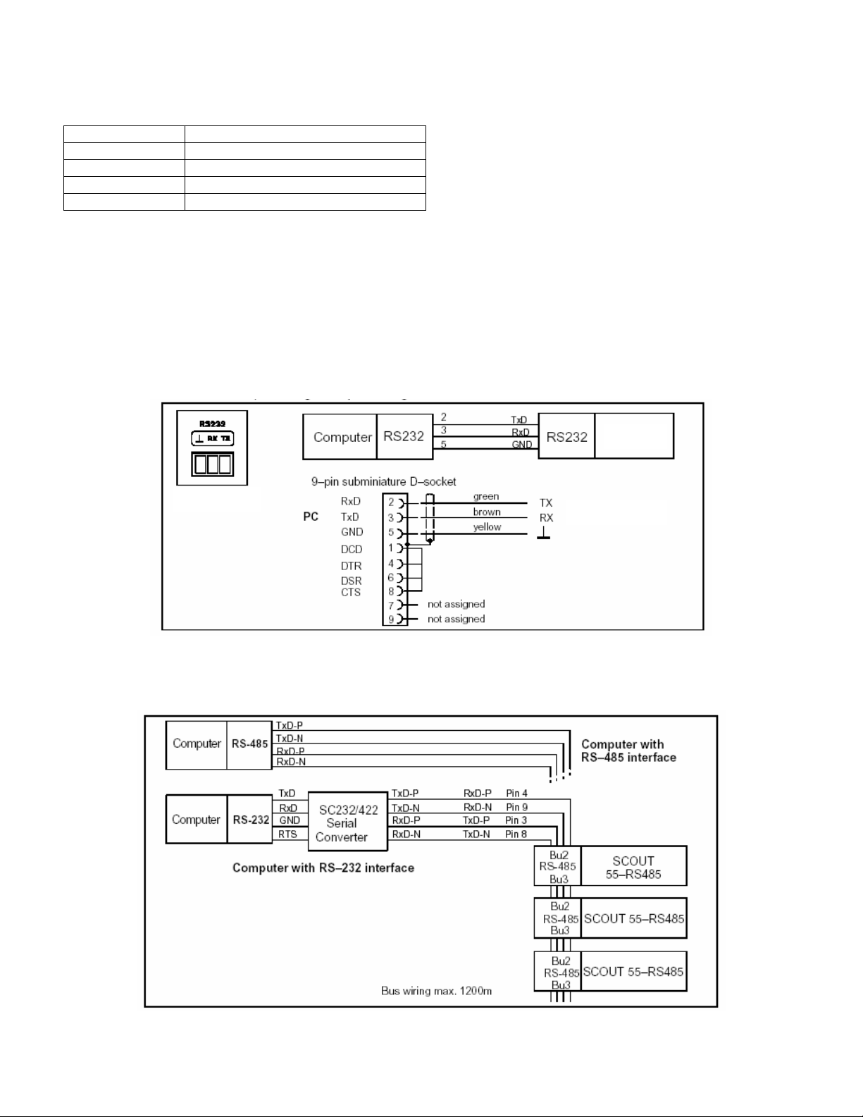
3.1 Connect DFI 2555 and computer
On the back of the instrument there is an RS232 serial interface for connecting a computer or terminal. For RS232
connection a connectorless cable (length 1.5m) and 9-pin subminiature socket* are supplied. Wiring and pin
assignment should be as illustrated below.
DFI 2555
Interface socket
on the DFI 2555
DFI 2555
*accessories
Figure 2: Computer / DFI 2555 connection
Figure 3: The RS485/422 bus with and without serial converter
CF 127 2 V. -A0109-5.3 en
Page 5

To connect the DFI 2555 to a computer proceed as follows:
• Connect both systems to the mains, leaving them switched off
• Connect the interface as shown in the diagram(s)
• The computer’s interface configuration (baud rate, data format) must match the DFI 2555’s basic setting. If it
does not, the interface configuration must be altered via the keypad (see DFI 2555 User’s Guide).
• Finally, switch both systems on.
When a printer is connected, a simple line printer operating at no more than 4 seconds per line is adequate. The
printout is in 12 columns. This corresponds to a line length of 132 characters.
3.2 Activation of the RS232C or RS485 interface
The Interpreter is activated by the following signal:
* CTRL R (DC2) computer operation without echo
Input of the control character puts the instrument into remote-operation mode; only the display’s output functions
can now be controlled. Computer operation without echo means that no command characters but only the data
generated are sent back to the DFI 2555. With the RS-232C interface each information-item generated is output as
soon as it is complete in the output buffer.
With the following command you can deactivate remote operation:
CTRL A (SOH); see also command DCL in Section 4.2.
4.0 COMMAND SET OF THE INTERPRETER
4.1 Important conventions
These conventions and general notes make working with the Interpreter’s commands easier for you.
Notation
• All commands can be input in lower or upper case.
Short commands
• Short commands consist of 3 to 5 characters and, depending on the command, a list of parameters separated
by commas.
e.g. BDR 6,2,1 (x)
Blanks
• Prefixed and following blanks in parameters are suppressed.
Command types
• Query commands – used for retrieving information – are identified by an added question mark (?)
e.g. BDR?
Responses
• The instrument’s responses given in the examples are shown in the User Manual in italics.
Command terminator
For input commands:
• (x) marks the command terminator. Permitted command terminators are: ”;”, LF, LFCR, CRLF
For output commands:
• (y) marks the command terminator. The command terminator is always CRLF.
I/O with numbers
• The numbers entered are changed to the relevant parameter’s numeric format
• Numbers are always output in fixed point format
CF 127 3 V. -A0109-5.3 en
Page 6

Serial interface
• With the RS232C interface, communication with a computer begins with the permitted control characters:
CTRL R or CTRL B and ends with CTRL A or the command DCL
• In the case of serial interfaces every command generates an output (response)
Acknowledgement
• Output commands – identified by a ? – always give rise to output data.
• Changing parameters
• If parameters affecting the measurement process itself are changed, calibration is performed after input; this
can take 1...3s.
Norms and standards
All commands used have a defined structure. There are essentially two types of command:
Set-up commands:
The DFI 2555 is set up through the computer.
Example: BDR6,2,1 (x)
0 (y)
The interface is set to 9600 baud, even parity and 1 stop bit.
Query commands:
Measured values or instrument settings are read from the
DFI 2555 and appear on the screen.
Example: BDR? (x)
6,2,1 (y)
The interface is set to 9600 baud, even parity and 1 stop bit.
4.1.1 Command structure
Short command Parameters End marker
TTT? p1,p2,...pn (x)
Example:
BDR? (x)
BDR Short commands as alphabetical characters (a...z)
? Only in query commands
p1,p2...pn Parameter values, consisting of sign (+/-) and numbers (0...9) or character strings (always in
quotation marks ” ”). A positive sign can be omitted.
, Separator
(x) Command terminator:
Line Feed (LF), Semi-colon (;) Carriage Return/Line Feed (CRLF) or Line Feed/Carriage
Return (LFCR)
CR ASCII characters: Carriage Return = decimal 13
LF ASCII characters: Line Feed = decimal 10
; ASCII characters: Semicolon = decimal 59
If an additional parameter - e.g. Parameter 2 - is omitted, at least the separator must be entered, e.g. ASA 1,,0(x)
If from a particular point all additional parameters are omitted, input can be concluded with the command
terminator.
4.1.2 Data-output Structure
q1,q2...qn (y)
Example 1:
IDN? (x)
HBM,MVD2555,0,P10 (y)
The responses sent by the DFI 2555 are printed in italics
q1,q2...qn Signed numerical values,
in this documentation (second line in the examples).
CF 127 4 V. -A0109-5.3 en
Page 7

Character strings (always in quotation marks) or ’?’ as an error message
; Separator
(y) End of sequence (CRLF)
4.2 Description of Individual Commands
On the following pages each command is listed, its structure analyzed and explained with an example.
Command
The character string that must be input to operate the instrument, e.g.:
BDR
Syntax
Mandatory notation for a command, e.g.:
BDR p1,p2,p3 (x)
BDR p1,,p3 (x)
Parameters
The meaning of any parameters is explained:
e.g. if for command ASA parameter p1=1, this means:
1V bridge excitation voltage
Effect
e.g. explanation of how the instrument is set up.
Response
The instrument responds to your input. In operation via terminal this response appears on the screen
(always in the case of output commands).
Example
The example shows you the command entered and the instrument’s response. The response is always
shown in italics.
Command
DCL Device Clear
Terminate communication
Syntax: DCL (x) or with RS232C/RS485 control character
CTRL A (ASCII code 01 decimal).
Parameters: none
Effect: Remote control operation is terminated.
Example: DCL(x)
Interpreter is no longer active.
Note:
ESR?
Output of the event-status register
Syntax: ESR? (x)
Parameters: none
Effect: Output of the contents of the standard event-status register (ESR) in decimal
q1 8, 16 or 32
Response: none
After this command you can input a new command only after approx. 3s.
Standard Event Status Register
equivalent.
The standard event-status register (ESR) is set if errors occur in communication.
Different causes of error set different bits, so that errors can be specified precisely.
Response: q1( y)
CF 127 5 V. -A0109-5.3 en
Page 8
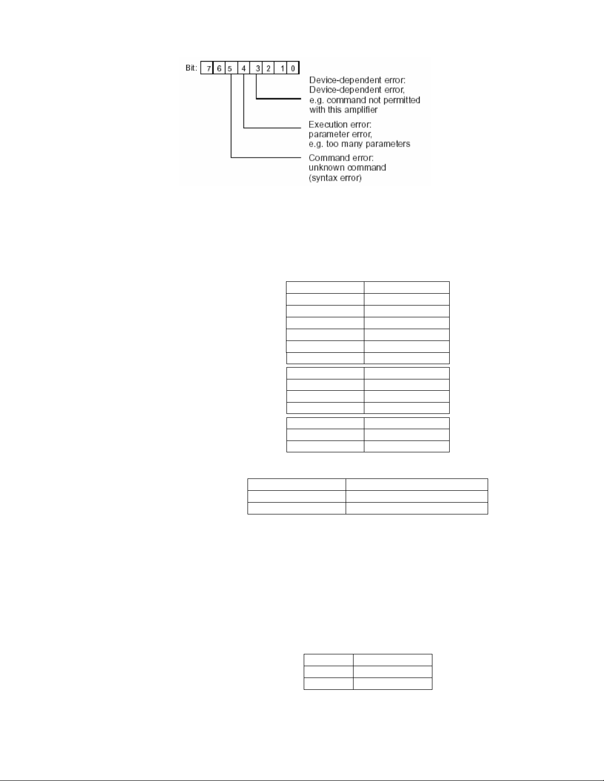
All other bits are undefined.
4.2.1 Setting-up of functions in the additional functions group
4.2.1.1 Setting of the RS232C interface parameters
Command
BDR Baud rate
Syntax: BDR p1,p2,p3 (x)
Parameters:
Transmission is always carried out with a character length of 8 bits.
Effect: The serial interfaces’ baud rate, parity bit and number of stop-bits are reset.
Response:
Example: The DFI 2555 is being operated via the RS232C interface:
Command
BDR?
Output serial-interface parameters
Syntax: BDR?(x)
Parameters: none
Effect: The serial interface’s set baud rate, parity bit and number of stop bits are output.
Response: q1,q2,q3 (y)
Example: BDR? (x)
Setting of the RS232C parameters
p1 Baud rate
1 300
2 600
3 1200
4 2400
5 4800
6 9600
p2 Parity
0 None
1 Odd
2 Even
p3 Stop Bits
1 1 stop bit
2 2 stop bits
Acknowledgement Meaning
0 Command has been executed
? Error
BDR6,2,1 (x)
0 (y)
The RS232C interface has been set to 9600 baud, even parity and 1 stop bit.
Baud Rate Query
q1 Baud rate
q2 Parity
q3 Stop bits
6,2,1 (y)
CF 127 6 V. -A0109-5.3 en
Page 9

The interface has been set to 9600 baud, even parity and 1 stop bit.
4.2.1.2 Setting of the RS485 interface parameters
ADR Address
Assign RS485 address to the instrument
Syntax: ADR p1(x)
Parameters:
Effect: The command specifies the instrument’s RS485 address (see also command Sxx
on next page).
Response:
Acknowledgement Meaning
ADR? Address Query
Output the device address
Syntax: ADR?(x)
Parameters: none
Effect: Output the device address.
The RS485 address can be set using the command ADR or via the keypad in the
additional functions under COMM.ADR.
Response:
q1(y)
Command
Sxx
Select
Selects the DFI with the address xx
Syntax: S00(x) to S99(x)
Parameters: none
Effect: With the Select command
you can actuate individually up to 32 MGC devices
connected to one RS422/485 bus. There are 32 usable addresses 0...31. With the
Select command these addresses are mapped again on to addresses 32...63 and
64...95, i.e. the commands S00, S32, S64 actuate the devices with the address 00, but
their effect on them is not the same. Addresses 96...99 are provided for special
functions.
Address Sxx Device with the
specified address Sxx
Execute
Command
00…31 Yes Yes2) No No
32…63 Yes Yes2) Yes No1)
64…95 Yes No1) as for last address selected
96 No No No No
97,98 Yes No1) Yes No1)
993) Yes Yes2) Yes Yes2)
1) The response to the previous command is stored internally.
2) The stored response to the previous command is output subsequently.
3) Factory setting
Explanation:
S00...S31(x)
Only the instrument with the specified address receives commands, executes them and responds.
S32...S63(x)
All instruments receive all commands and execute them. Only the instrument with the specified address (S32 =
device 0) responds on behalf of all instruments.
p1 Device address
0…31
0 Command has been executed
? Error
q1 Device address
0…31
All other devices
Responses Execute
Responses
Command
CF 127 7 V. -A0109-5.3 en
Page 10

S64...S95(x)
The instrument with the specified address is accepted as a supplementary station that receives and executes all
commands but sends no responses.
S96(x)
All instruments wait for Select and send no responses.
S97 (x) or S98(x)
All instruments receive all commands and execute them, but send no responses.
S99(x)
All instruments on the bus are active, receive all commands and send responses (where there are multiple stations
this leads to collisions on the bus). Presetting of the devices after switching on (default).
Response: none
Example: S03(x)
Instrument with the address 03 executes all commands and responds.
S35(x)
All instruments on the bus receive and also execute all commands. Instrument with the address 03 (35-32)
responds on behalf of all instruments.
4.2.1.3 Querying for Device Identification/Firmware Status.
Command
AID?
Output of device identification
Syntax: AID?(x)
Parameters: none
Effect: Output of amplifier identification (firmware status)
Example: AID? (x)
Instruction
SNR? Serial Number
Output serial number of device
Syntax: SNR?
Parameter: None
Effect: Output of the serial number of the device
Response: Character string (10 characters)
Example: SNR? (x)
Response: Character string (20 characters)
Amplifier Identification Query
HBM,MVD2555,0,P15 (y)
Company, device designation, serial number, software version number
4021837410
4.2.1.4 Print functions
Command
PFS
Define print-format
Syntax: PFS p1 (x)
Parameters:
Effect: Signal to be printed is specified.
Print Format Select
p1 Signal to be printed
0 Value shown on the display
1 Gross value
2 Net value
4 Peak value1 (maximum)
8 Peak value2 (minimum)
16 Peak value3 (peak-to-peak)
63 All signals and status of limit values
You can set all signal-combinations by totaling the code numbers.
CF 127 8 V. -A0109-5.3 en
Page 11

The setting affects print-output through the initiation of printing (key, remote)
Response:
Acknowledgment Meaning
0 Command has been executed
? Error
Example: Gross value, Net value are to be printed
p1 = 1+2
PFS 3 (x)
0 (y)
Command
PFS?
Print Format Select Query
Query print-format
Syntax: PFS?(x)
Parameters: none
Effect: Signal being printed is output.
Response: q1 (y)
Signal, or signal-combination which was set with the PFS command (Coding: see
PFS command).
Example: PFS? (x)
1 (y)
The gross signal is printed (initiation via key or remote).
4.2.2 Setting-up of the Parameter-sets group
Command
MDD
Input of amplifier set-up data
Syntax: MDD p1 (x)
Parameters: p1
Effect: The command is used to save and recall complete set-ups.
Response:
Memory Device Data
Amplifier set-up data obtained from the amplifier with the MDD? command (as a
hexadecimal string ” ___ ”, approx. 100 bytes = 200 characters).
To change individual parameters, please use the relevant command (e.g. IMR).
Acknowledgment Meaning
0 Command has been executed
? Error
Example: MDD ”____(hexadecimal string)____” (x)
0 (y)
The amplifier is now set up.
Command
MDD?
Memory Device Data Query
Output of amplifier set-up data
Syntax: MDD? (x)
Parameters: none
Effect: The amplifier’s set-up parameters are output.
Response: ”___( hexadecimal string)___” (y) ”approx. 100 bytes = 200 characters
Example: MDD? (x)
”0a00ff.......” (y)
All set-up parameters are output.
Command
TDD
Transmit Device Data
Save amplifier settings
Syntax: TDD p1,p2 (x)
CF 127 9 V. -A0109-5.3 en
Page 12

Parameters:
p1 Amplifier settings
0 Factory settings (set-up)
1 RECALL from parameter set 1…8
2 SAVE from parameter set 1…8
3 Automatic saving of zero/tare values
if p1=0 (factory setting); p2 no effect
if p1=1 or p1=2 ; p2=parameter-set no.
p2 Number of the parameter set
(if p1=1 or p1=2)
1..8 Parameter set 1 to 8
if p1=3: p2=1, status of automat. saving of zero/tare values
p2 Status of automatic zero/tare value saving
(if p1=3)
0 Off
1 On
Effect: The amplifier settings are saved or stored. Automatic saving of zero/tare values to
the EEPROM can be switched on or off.
Response:
Acknowledgment Meaning
0 Command has been executed
? Error
Example 1: TDD2,8 (x)
0 (y)
The current amplifier settings are stored in parameter set 8.
Note: This command triggers a calibration process that permits communication to
continue only after 1...3s.
Example 2: TDD3,1 (x)
0 (y)
Automatic saving of zero/tare values is switched on. At each zeroing the zeroing
value is stored in the current parameter set. At each taring the tare value is stored
in the current parameter set.
Command
TDD?
Transmit Device Data Query
Query source of the amplifier settings.
Syntax: TDD?p1 (x)
Parameters:
p1
0 Source of the amplifier setting
3 Status of automat. saving of zero/tare values
Effect: The source of the currently active amplifier setting is output or the status of
zero/tare value saving is indicated.
Response: if p1 = 0; q1 shows the source of the amplifier settings
q1 Source of the amplifier settings
1…8 Parameter set 1…8
? Error
if p1 = 3; q1 corresponds to the status of tare/zero value saving
q1 Status of automat. saving of zero/tare
0 Off
1 On
CF 127 10 V. -A0109-5.3 en
Page 13

Example1: TDD?0 (x)
2 (y)
The source of the currently active amplifier setting is parameter set 2.
Example 2: TDD?3 (x)
1 (y)
Automatic saving of zero/tare values is switched on.
4.2.3 Define output format, measurement output
4.2.3.1 Define output format
Command
COF
Change format of measurement output
Syntax: COF p1 (x)
Parameters:
Change Output Format
p1 Measurement output format
0 Measured value, status (ASCII format)
1 Measured value (ASCII format)
2 Binary measurement output 4 bytes (MSB XXXX LSB)
3 Binary measurement output 4 bytes (LSB XXXX MSB)
4 Binary measurement output 2 bytes (MSB LSB)
5 Binary measurement output 2 bytes (LSB MSB)
6 BCD measurement output
Binary 4-byte output:
Binary 2 byte output: 1=MSB, 2=LSB
BCD output:
Measured values are scaled to the indication upper limit. Where output is in ASCII
format, account is taken of the decimal point. In binary/BCD format the decimal
point must be included by the user in processing of measured values.
Effect: With the following MSV commands measured values are output in the preferred
form.
CF 127 11 V. -A0109-5.3 en
Page 14

Response:
Acknowledgment Meaning
0 Command has been executed
? Error
Example: COF0 (x)
0 (y)
Measured values and status are output in ASCII format.
Command
COF?
Change Output Format Query
Query format of measurement output
Syntax: COF?(x)
Parameters: none
Effect: Code number for the output format is output.
Response: q1 (y)
Example: COF?(x)
0 (y)
ASCII format is set as the output format for measured value and status.
4.2.3.2 Specify measurement output
Command
MSV?
Output of the measured value
Syntax: MSV p1,p2 (x)
Parameters:
Measuring Signal Value Query
p1 Signal
1 GR Gross (with display filtering)
2 NET Net (with display filtering)
3 STORE1 Peak value 1 (maximum)
4 STORE2 Peak value 2 (minimum)
5 STORE3 Peak value 3 (peak-to-peak)
6 LVS1 Level
7 LVS1 Hysteresis
8 LVS2 Level
9 LVS2 Hysteresis
10 LVS3 Level
11 LVS3 Hysteresis
12 LVS4 Level
13 LVS4 Hysteresis
14 GR Gross (dyn., without filtering)
15 NET Net (dyn., without filtering)
p2 Number of measured values
0 Send continuously
1…65535 Default = 1
Effect: The measured value from the required signal p1 is output. Format dependent on the
last COF command.
Response: Measured value (output format: see COF command).
CF 127 12 V. -A0109-5.3 en
Example 1: Output in full ASCII format
COF0(x)
0 (y)
Fetch a gross measured value.
MSV?1 (x)
9,998.0 (y)
Status byte*
Measured value = 9.998
Fetch three net measured values.
Page 15

* See 4.2.3.1
MSV?2,3 (x)
9,998.0 CRLF
9,998.0 CRLF
9,998.0 CRLF (y)
Status byte*
Measured value = 9.998
Example 2: Output in 4 byte binary format
Binary 4 byte format
COF2 (x)
0 (y)
Fetch a gross measured value.
MSV?1 (x)
#0ffeedd00CRLF(y)
Status byte*
3 byte measured value
Identification key for binary output
Example 3: Continuous output
Gross measured values are output continuously.
MSV?1,0 (x)
#0ffeedd00CRLF
#0ffeedd00CRLF
#0ffeedd00CRLF
STP(x) Terminate output
Command
STP
Stop
End of measurement output
Syntax: STP (x)
Parameters: none
Effect: The measurement output initiated with MSV?1,0 is stopped.
Response: none
Example: STP (x)
4.2.4 Setting up the Adaptation group functions
4.2.4.1 Setting up amplifier input
Command
ASA
Input bridge excitation voltage, transducer type and input range
Syntax: ASA p1,p2,p3 (x)
Parameters:
Amplifier Sensor Adaptation
P1 Bridge excitation voltage
1 1 V
2 2.5 V
P2 Transducer type
1 Full bridge
2 Half bridge
3 LVDT
P3 Input signal range (at Eop)
1 4mV/V (Eop=2.5 V) / 10mV/V (Eop=1V)
2 40mV/V / 100mV/V
3 400mV/V / 1000mV/V
Effect:
Response:
Bridge excitation voltage, transducer type and input-signal range are set.
Acknowledgement Meaning
0 Command has been executed
CF 127 13 V. -A0109-5.3 en
? Error
Page 16

Example: The DFI 2555 is being set up:
ASA1,2,2 (x)
0 (y)
The DFI 2555 is set to bridge excitation voltage 1 V, half bridge and input-signal
range 100mV/V.
Command
ASA?
Amplifier Sensor Adaptation Query
Output bridge excitation voltage, transducer type and input range
Syntax: ASA?p1(x)
Parameters:
p1
0 Output bridge excitation voltage, transducer type and input-
signal range settings
1 Output table of possible settings for bridge excitation voltage,
transducer type and input-signal range
Effect: The amplifier outputs the bridge excitation voltage, transducer type and input-
signal ranges.
Response: ASA?0 (x)
q1,q2,q3 (y)
q1 Bridge excitation voltage
q2 Transducer type
Example: ASA?0 (x)
q3 Input signal ranges
1,2,2 (y)
The DFI 2555 is currently set to bridge excitation voltage 1V, half bridge and inputsignal range
100mV/V.
Response:
ASA?1 (x)
q1,q2,q3 (y)
Table of available settings
q1 Bridge excitation voltage
q2 Transducer type
Example: ASA?1 (x)
q3 Input signal ranges
Amplifier’s response:
”01.002.50”, ”123”, ”123”(y)
4.2.4.2 Choose filter settings
Command
ASF Amplifier Signal Filtering
Syntax: ASF p1,p2(x)
Parameters:
Effect: The low-pass filter is set to a frequency value and set of filter characteristics.
Response:
Example: Input of cutoff frequency and filter characteristics:
Input of cutoff frequency and filter characteristics
p1 Filter frequency
1..n Code number for frequency value (corresponds to the index from the
frequency table, which can be output with the command ASF?0) see below.
p2 Filter characteristics
1 Bessel
2 Butterworth
Acknowledgement Meaning
0 Command has been executed
? Error
ASF 10,1(x)
0 (y)
CF 127 14 V. -A0109-5.3 en
Page 17

The Filter is set to a cutoff frequency of 40Hz and Bessel characteristics (see
Command ASF?)
Command
ASF? Amplifier Signal Filtering Query
Syntax: ASF?p1(x)
Parameters:
Output of cutoff frequency and filter characteristics.
p1 Filter code number
0 Current filter settings
1 Frequency table (Bessel and Butterworth)
Effect: Output of the low-pass filter parameters, i.e. set cutoff frequency and filter
characteristics
Response: If p1 =0
q1,q2 (y)
q1 Code number for the filter frequency
q2 Filter characteristics (1=Bessel, 2=Butterworth)
Table of available filter frequencies (Bessel/Butterworth)
Example: Table of available filter frequencies
ASF?1 (x)
”0.050 0.100 0.200 0.500 1.250 2.500 5.00 10.00 20.00 40.00 100.0 200.0 400.0”,
”5.000 10.00 20.00 40.00 80.00 200.0” (y)
The following table shows a summary of the available cutoff frequencies and the
index of the frequency to be set (each element is 5 characters long).
p1 Bessel frequencies (Hz) Butterworth frequencies (Hz)
1 0.050 5.000
2 0.100 10.00
3 0.200 20.00
4 0.500 50.00
5 1.250 80.00
6 2.500 200.0
7 5.000 500.0
8 10.00
9 20.00
10 40.00
11 100.0
12 200.0
13 400.0
Command
MTC Motion Control
Syntax:
Parameters:
Specify motion-count indication (measured values/tolerance band/output)
MTC p1,p2,p3 (x)
p1 Number of measured values
0 Motion count indication off
1..255 Number of measurements; in conjunction with the chosen filter frequency
p2 Tolerance band
In digits
p3 Motion-count indication output status
0 No output of status via “WARNING”
1 Output of status via “WARNING”
Effect: The motion-count indication function is set up.
Example: MTC 200,10,1 (x)
0 (y)
this yields the corresponding time-span
CF 127 15 V. -A0109-5.3 en
Page 18

Assumption:
Filter setting: f<2.5Hz = sampling rate of 1200 values/sec
Indication upper limit: 100.00N, resulting in a time span of 166ms
Motion count indication is set:
If 200 measured values lie within a tolerance band of
0.1N (10 digits), motion-count indication is activated.
The status is also output via ”WARNING”.
Command
MTC? Motion Control Query
Syntax: MTC?p1(x)
Parameters:
Output of motion-count indication
p1
0 Motion-count indication settings
Effect: Output of motion–count indication settings
Response: If p1=0; output of motion–count indication
1 Motion-count indication status
settings
q1,q2,q3 (y)
q1 Number of measured values
q2 Tolerance zone in displayed units
q3 “WARNING” output status
If p1=1; q1 shows the status of motion-count indication
Example: MTC?0 (x)
0,0,0 (y)
Motion-count indication has not been activated. The status of motion-count indication
is not output via ”WARNING”.
4.2.4.3 Setting autocalibration
Command
ACL Autocal
Syntax: ACL p1 (x)
Parameters:
Effect: Switchover of autocalibration setting
Response:
Example: ACL1 (x)
Hint: A calibration is triggered and cyclic autocalibration is switched on. This interrupts the
Command
ACL? Autocal Query
Syntax: ACL ? (x)
Parameters: none
Switching on/off of autocalibration
Acknowledgment Meaning
0 (y)
measurement process approximately every 5 minutes and calibrates the amplifier. If
such interruption during a measurement process would be a problem, automatic
calibration must remain switched off.
Switching on/off of autocalibration
q1 Motion-count indication status
q2 No standstill; conditions not satisfied
q3 Standstill; conditions satisfied
p1 Automatic calibration
0 Switch off
1 Switch on
0 Command has been executed
? Error
CF 127 16 V. -A0109-5.3 en
Page 19

Response:
Command
CAL
Response:
Effect: Status of autocalibration is output.
q1 Status
0 Autocalibration is off
Example: ACL? (x)
1 (y)
Autocalibration has been switched on.
Calibrate
Calibration
Syntax: CAL (x)
Parameters: none
Effect: A single calibration is triggered.
Acknowledgment Meaning
Example: CAL (x)
0 (y)
Calibration is performed.
Note: This command initiates a single calibration, permitting further communication
only after 1 to 3s.
1 Autocalibration is on
0 Command has been executed
? Error
4.2.5 Setting up the Calibration group functions
4.2.5.1 Selecting the unit of measure
Command
ENU
Response:
Command
ENU? Engineering Unit Query
Engineering Unit
Input of the unit of measure
Syntax: ENU p1(x)
Parameters:
Effect: The unit of measure is set.
Example: ENU11(x)
0 (y)
kN is set as the unit of measure.
Output of the unit of measure
Syntax: ENU?p1(x)
Parameters:
p1 Input of the unit of measure
1…n Code number for the desired unit of measure (see table)
Acknowledgment Meaning
0 Command has been executed
? Error
p1 Output of the unit of measure
0 Output of currently set unit of measure
1 Output of all available settings
CF 127 17 V. -A0109-5.3 en
Effect: The currently selected unit of measure is output
Response: q1 (y)
Example 1: ENU?0 (x)
Example 2: ENU?1 (x)
11 (y)
kN has been selected as the unit of measure
”mV/V, V, g, kg, T, kT, TON, LB, oz, N, kN, bar, mbar, Pa, PAS, HPas, KPas
PSI, µm, mm, cm, m, Inch, Nm, kNm, FTLB, INLB, µm/m, m/s, m/ss, %, ‰, PPM s,
MP, MN ” (y)
Page 20

Summary of all available units and code numbers
Index Index Index Index
1 mV/V 13 mbar 25 kNm 37 MN
2 V 14 Pa 26 FTLB 38 A
3 g 15 PAS 27 INLB 39 mA
4 kg 16 HPas 28 µm/m
5 T 17 kPas 29 m/s
6 kT 18 PSI 30 m/ss
7 TON 19 µm 31 %
8 LB 20 mm 32 %0
9 oz 21 cm 33 PPM
10 N 22 m 34 s
11 kN 23 inch 35 “blank”
12 bar 24 Nm 36 MP
4.2.5.2 Selecting the indication upper limit
Command
IAD Indication Adaptation
Syntax: IAD p1,p2,p3 (x)
Parameters:
Effect: This command is used to input the indication adaptation values.
Note: For ”V” and ”mV/V” scaling is fixed.
Response:
Example: IAD 10000,3,4 (x)
Command
IAD? Indication Adaptation Query
Syntax: IAD?(x)
Parameters: none
Effect: Output of the current settings for indication upper limit, decimal point, step width
Response: q1,q2,q3 (y)
Parameters: see IAD command
Example: IAD? (x)
Input, indication upper limit, decimal point, step width
p1 Indication upper limit without decimal point (max. 200000)
p2 Decimal point (number of decimal places 0…5)
p3 Step width (see table)
p3 Step width
1 1
2 2
3 5
4 10
5 20
6 50
7 100
8 200
9 500
10 1000
Acknowledgment Meaning
0 Command has been executed
? Error
0 (y)
Indication adaptation is set to:
indication upper limit 10,000 with step width 10
Output input, indication upper limit, decimal point, step width
10000,3,4 (y)
Indication adaptation is set to:
CF 127 18 V. -A0109-5.3 en
Page 21

indication upper limit 10,000 with step width 10
4.2.5.3 Setting zero value
Command
CDW Calibration Dead Weight
Response:
Command
CDW? Calibration Dead Weight Query
Syntax: CDW (x) or CDW p1(x)
Parameters: p1 (optional)
Effect: The value entered is stored in the amplifier’s zero store.
Example 1: Start zeroing
CDW (x)
Example 2: Input zero value 2.0000 mV/V (selected input range 4 mV/V)
CDW 2.0000(x)
Syntax: CDW?p1(x)
Parameters:
Start zeroing /Input zero value (balance)
p1 Zero value in mV/V
0 (y)
The current measured value is adopted as zero value.
0 (y)
If for p1 the value read with CDW?1 is sent, the adjacent measurement signal is
set to zero.
Output of zero value
Value is input in mV/V; within the input-signal range
Acknowledgment Meaning
0 Command has been executed
? Error
p1 Zero value
0 Currently set zero value (mV/V)
1 Current measured value (mV/V)
Response: q1 (y)
Effect: This command causes the currently set zero value or currently adjacent measured
value to be output.
Example 1: CDW?0 (x)
3.256 (y)
Currently set zero value is 3.256 mV/V.
Example 2: CDW?1 (x)
2.001 (y)
Measured value currently applied is output. CDW2.001sets this signal to zero.
4.2.5.4 Set measuring range
Command
IMR Input Measuring Range
Response:
Syntax: IMR p1(x)
Parameters:
Effect: The measuring range is set.
Example: IMR 2.0 (x)
Input of the upper limit of the measuring range
p1 Upper limit of the measuring range in mV/V
0 (y)
Value is input in mV/V; within the input signal range
Acknowledgment Meaning
0 Command has been executed
? Error
CF 127 19 V. -A0109-5.3 en
Page 22

The measuring range is set to 2.0 mV/V.
Command
IMR? Input Measuring Range Query
Syntax: IMR?p1(x)
Parameters:
Output of the upper limit of the measuring range
p1 Upper limit of the measuring range
0 Current measuring range in mV/V
1 Current measuring signal in mV/V
2 Maximum and minimum adjustable upper limits of the
measuring range in mV/V
Effect: Output of the set measuring range.
Response: q1,q2 (y)
Example 1: IMR?0 (x)
1.987 (y)
Currently set upper limit of the measuring range is 1.987 mV/V.
Example 2: IMR?2 (x)
4.0,0.2 (y)
With a selected input-signal range of 4 mV/V, 4.0 mV/V is output as the maximum
and 0.2 mV/V as the minimum value.
4.2.5.5 Tare
Command
TAR Tare Instruction
Response:
Command
TAR? Tare Value Query
Syntax: TAR (x) or TAR p1(x)
Parameter: p1 (optional) or tare value in displayed units
Effect: This command tares the signal/sets a tare value.
Example 1: Start taring
The current measured value is adopted as tare value.
Note: Taring is done computationally, not by balancing of the input signal.
Example 2: TAR200.0 (x)
Syntax: TAR?(x)
Parameters: none
Effect: The tare value is output in displayed units.
Response: q1 (y)
Tare value in displayed units
Example: TAR? (x)
Start taring/Input tare value
Acknowledgment Meaning
0 Command has been executed
TAR (x)
0 (y)
0 (y)
Input value is written to the tare store.
Output tare value
200.0 (y)
Suppose, for example, that an indication upper limit of 2000.0kN has been set. The
tare value is 200.0kN.
? Error
4.2.6 Setting up the Limit Value 1...4 group functions
Command
LIV Limit Value
CF 127 20 V. -A0109-5.3 en
Page 23

Syntax: LIV p1,p2,p3,p4,p5,p6,p7,p8 (x)
Parameters:
Input of limit monitor settings
p1 Limit monitors
1 1
2 2
3 3
4 4
p2 Limit value monitoring
0 OFF
1 ON
p3 Source of limit values
1 Gross value
2 Net value
3 Peak value store 1 (maximum)
4 Peak value store 2 (minimum)
5 Peak value store 3 (peak-to-peak)
p4 Operating directions
1 Operates when overrange occurs
2 Operates when underrange occurs
p5 Limit value level in displayed units
Value is specified in displayed units (e.g. kN)
p6 Hysteresis value in displayed units.
Value is specified in displayed units (e.g. 100kN); always positive
p7 Output logic of the limit monitors
1 Active corresponds to On
2 Active corresponds to Off
p8 Level-setting by limit value key in measuring mode
0 Locked
1 Enabled
Effect: With this command limit monitor p1 is activated, set to input signal p3, switching
direction p4, switching-level p5, and also to hysteresis p6 and output logic p7.
Level-setting by the limit value key is set to p8.
Response:
Acknowledgment Meaning
Example: LIV1,1,3,1,100,10,1,1 (x)
0 (y)
Limit monitor 1 has been activated and the input signal assigned to Store/Max
(maximum). The limit monitor on exceeding of the On-level of 100kN and hysteresis
of 10kN (Off-level 90kN). The control output is active. Level-setting by limit value
key for LV1 is possible.
Important:
All limit monitors required for the measurement process must be set in sequence
according to the above scheme.
Command
LIV? Limit Value Query
Syntax: LIV? p1,p2 (x)
Output of the limit-monitor settings
0 Command has been executed
? Error
CF 127 21 V. -A0109-5.3 en
Page 24

Parameters:
p1 Limit monitors
0 Query the signal value of p2 (output in displayed units)
1 Current LV1 settings
2 Current LV2 setting
3 Current LV3 setting
4 Current LV4 setting
P2 Signal code-number, if p1=0
1 Current gross signal in displayed units
2 Current net signal in displayed units
3 Current maximum value in displayed units
4 Current minimum value in displayed units
Effect: This command causes the setting of limit monitor p1 to be output.
5 Current peak-to-peak value in displayed units
Response: q1,q2,q3,q4,q5,q6,q7,q8 (y)
q1 Number of the limit monitor
q2 Limit value monitoring On/Off
q3 Input signal of the limit monitor
q4 Operating direction positive/negative
q5 Switching level of the limit monitor
q6 Hysteresis value
q7 Logic of the control output
Example 1: LIV?2 (x)
q8 Level-setting in measuring mode
2,1,3,1,100,10,1,1 (y)
Limit monitor 2 has been activated and the input signal assigned to Store/Max
(maximum). The limit monitor operates if the level of 100kN is exceeded
(corresponds to On-level). Hysteresis is 10kN (Off-level 90kN). The control output
is active. Level-setting by limit value key for LV2 is enabled.
Example 2: LIV?0,3 (x)
200 (y)
The value stored in Store1/Max is 200kN.
4.2.7 Setting up the functions of the Peak value store group
Command
PVS Peak Value Select
Syntax: PVS p1,p2,p3,p4 (x)
Parameters:
Effect:
Response:
Input of the peak value store settings
p1 Peak value store
1 Maximum
2 Minimum
3 Peak-to-peak
p2 Peak value determination (applies to all stores)
0 Off
1 On
p3 Source of stores
1 Gross value
2 Net value
p4 Envelopes (applies to all stores)
0 Envelope function is off
00100…60000 Timing constant in ms
This command is used to set the function of the peak value store p1.
Acknowledgment Meaning
0 Command has been executed
CF 127 22 V. -A0109-5.3 en
Page 25

Command
PVS? Peak Value Select Query
Response: q1,q2,q3,q4 (y)
Example: PVS1,1,1,0 (x)
0 (y)
The gross signal is assigned to peak value store 1 (maximum). All peak value
stores are enabled; the envelope function is switched off.
Output of peak value store settings
Syntax: PVS?p1(x)
Parameters: p1
Code number for the peak value store (see command PVS)
Effect: This command causes the setting of peak value store p1 to be output.
q1 Code number for the peak value store
q2 Peak value determination On/Off
q3 Source of store
q4 Timing constant for envelope function in ms
? Error
Command
CPV Clear Peak Value
Response:
Example: PVS?1 (x)
1,1,1,0 (y)
The gross signal has been assigned to peak value store 1 (maximum). All peak
value stores are enabled; the envelope function is switched off.
Clear peak value store
Syntax: CPV (x)
Parameters: none
Effect: This command clears the peak-–value stores
Acknowledgment Meaning
0 Command has been executed
Example: CPV (x)
0 (y)
Peak value store 1 (max), peak value store 2 (min) and peak value store 3 (min-
max) are cleared.
Note: After clearing of the peak value store the output signal of stores 1 and 2 is the
adjacent measured value. Store 3 (min-max) has the value zero.
? Error
4.2.8 Setting up the functions of the Inputs/Outputs group
4.2.8.1 Select amplifier input signal
Command
ASS Amplifier Signal Select
Response:
Syntax: ASS p1(x)
Parameters:
Effect: Selection of the amplifier input signal.
Example: The DFI 2555 is being set up:
Select amplifier input signal
p1 Input source
0 Internal zero signal
1 Internal calibration signal
Acknowledgment Meaning
2 Measuring signal
0 Command has been executed
? Error
CF 127 23 V. -A0109-5.3 en
Page 26

ASS 0(x)
0 (y)
The amplifier input is switched to internal zero signal.
Note: This command triggers a calibration process which permits communication to
continue only after 1...3s.
To resume measurement, enter p1=2
Command
ASS? Amplifier Signal Select
Syntax: ASS?(x)
Parameters: none
Effect: The amplifier input signal’s type is output
Response: q1 (y)
Output amplifier input signal
q1 Amplifier’s input signal source
0 Internal zero signal
1 Internal calibration signal
Example: ASS? (x)
2 Measuring signal
2 (y)
Amplifier input is switched to the measuring signal.
4.2.8.2 Setting up the analog output
Command
OPS Output Path Select
Syntax: OPS p1,p2 (x)
Parameters:
Effect: A signal is assigned to the analog output and the operating mode is set.
Note*): The analog output (voltage or current) is selected by rearranging jumpers on the
Response:
Assign signal to the analog output and select operating mode
P1 Signal
1 Gross signal at analog output
2 Net signal at analog output
3 Store 1 (maximum) at analog output
4 Store 2 (minimum) at analog output
5 Store 3 (peak-to-peak) at analog output
P2 Mode of analog output (U/I)*
0 Analog output OFF
1 +/- 10V (U) / +/- 20mA (I)
2 No funct. (U) / 4…20mA (I)
PCB. The setting-up procedure is described in the DFI 2555 User’s Guide.
Acknowledgment Meaning
0 Command has been executed
? Error
Example: OPS1,1 (x)
0 (y)
The gross signal is assigned to the analog output. +/– 10V is set as the operating
mode.
(Assumption: voltage has been specified as the analog output signal)
Command
OPS? Output Path Select Query
CF 127 24 V. -A0109-5.3 en
Syntax: OPS?p1(x)
Output input-signal of the analog output and operating mode
Page 27

Parameters:
p1 Analog output: signal and operating mode
0 Currently assigned input signal
1 “Voltage” or “current” operating-mode set
Response: q1,q2 (y)
Effect: The analog output’s currently assigned input signal is output or the selected
operating-mode is output.
q2 corresponds to parameter p2 (see command OPS)
q1 Operating mode (set)
1 Voltage
Example: OPS?0 (x)
2 (y)
The net signal is now assigned to the analog output.
Example: OPS?1 (x)
2,2 (y)
Current output set; mode 4...20mA selected
2 Current
4.2.8.3 Setting up remote control
Command
LOR Local/Remote
Response:
Command
LOR? Local / Remote Query
Syntax: LOR p1 (x)
Parameters:
Effect: Switching to remote control of certain amplifier functions via remote control inputs.
Example: LOR1 (x)
Syntax: LOR? (x)
Parameters: none
Effect: Local/Remote control status is output
Response: q1 (y) corresponds to p1 (see command LOR)
Example: LOR? (x)
Switching between Local/Remote
p1 Status
0 Remote, remote control through remote outputs
0 (y)
Local control is enabled, i.e. all set-up functions for amplifier parameters via the
remote control inputs are blocked.
Query Local / Remote status
0 (y)
Remote control is enabled, i.e. all set-up functions for amplifier parameters via the
remote control inputs are enabled.
1 Local, no remote control
Acknowledgment Meaning
0 Command has been executed
? Error
4.2.8.4 Setting up assignment of the remotes
Command
RFP Remote Function Programming
Syntax: RFPp1,p2 (x)
Parameters: p1 corresponds to the number of the remote (1..6)
Assignment of remote functions
p2 corresponds to the code number of the function(see table)
CF 127 25 V. -A0109-5.3 en
Page 28

p2 Function
0 NOP No function
1 ACAL Autocalibration
2 TARE Taring
3 CPV1 Store 1/Curr
4 HLD1 Store 1/Hold
5 CPV2 Store 2/Curr
6 HLD2 Store 2/Hold
7 ZERO Zeroing
8 PRNT Print
9 PAR1 Bit for querying param. set 1…8
10 PAR2 Bit for querying param. set 1…8
11 PAR3 Bit for querying param. set 1…8
The default assignment after a ”Set-up” of the instrument is ”No function” for all
remotes. The functions PAR1, PAR2 and PAR3 can be used to retrieve the eight
parameter sets in binary form (000 to 111) (see DFI 2555 User’s Guide).
Effect: The remote’s effect on the selected amplifier functions is specified.
Response:
Acknowledgment Meaning
0 Command has been executed
Example: RFP 2,1 (x)
? Error
0 (y)
The Autocal function (Acal) is now assigned to remote 2.
Note: Switching between Remote and Local remains possible even when the instrument
is in local status.
Command
RFP? Remote Function Programming Query
Syntax: RFP?p1(x)
Parameters:
Query re: assignment of the remote functions
p1
0 Output table of available functions
1…6 Output assignment of remote functions
Effect: Output assignment of remote functions at the cable-connector
Example 1: RFP?0 (x)
”NOPACALTARACPV1HLD1CPV2HLD2NULLPRNTPAR1PAR2PAR3” (y)
Response: q1 (y)
Example 2: RFP?2 (x)
1 (y)
The Autocal function (Acal) is now assigned to remote 2.
4.2.9 Setting up the Adaptation group functions
4.2.9.1 Lock-control of the keys
Command
KLC Key Lock Control
Syntax:
Parameters:
CF 127 26 V. -A0109-5.3 en
Key lock control
KLC p1,p2 (x)
p1 Key lock control
1 Set LVS key
2 ZERO key
3 TARE key
4 Clear STORE key
5 Initiate PRINTING key
6 Select SIGN key
p2 Key authorization
Page 29

0 Lock
Response:
Command
KLC? Key Lock Control Query
Response:
Effect: Direct keys can be individually locked.
Acknowledgment Meaning
Example: KLC 2,0 (x)
0 (y)
The ZERO key has been locked.
Querying key-lock control
Syntax: KLC?p1 (x)
Parameters: p1 corresponds to the key selected (see command KLC)
Effect: Enablement status of the selected key is output.
1 Free
0 Command has been executed
? Error
q1 Key status
0 Locked
1 Enabled
Example: KLC?2 (x)
0 (y)
The ZERO key has been locked.
5.0 ABBREVIATION/COMMAND INDEX
ABBREVIATION COMMAND SECTION
A
ACL
ACL?
ADR
ADR?
AID?
ASA
ASA?
ASF
ASF?
ASS
ASS?
Autocal
Enable/disable autocalibration
Autocal Query
Enable/disableAutocalibrationAutocalibration
Address
Assign an address to the device
Address Query
Output address of devices
Amplifier Identification Query
Output device identification
Amplifier Sensor Adaption
Enter excitation voltage, transducer type and input range
Amplifier Sensor Adaption Query
Output excitation voltage, transducer type and input range
Amplifier Signal Filtering
Input cutoff frequency and filter characteristics
Amplifier Signal Filtering Query
Output cutoff frequency and filter characteristics
Amplifier Signal Select
Select amplifier input signal
Amplifier Signal Select
Output amplifier input signal
4.2.4.3
4.2.4.3
4.2.1.2
4.2.1.2
4.2.1.3
4.2.4.1
4.2.4.1
4.2.4.2
4.2.4.2
4.2.8.1
4.2.8.1
B
BDR
BDR?
Baud Rate
Set serial interface parameters
Baud Rate Query
Output serial interface parameters
4.2.1.1
4.2.1.1
CF 127 27 V. -A0109-5.3 en
Page 30

C
CAL
CDW
CDW?
COF
COF?
CPV
Calibrate
Calibration
Calibration Dead Weight
Start zeroing / enter zero value (balance)
Calibration Dead Weight Query
Output zero value
Change Output Format
Change measurement output format
Change Output Format Query
Request measurement output format
Clear Peak Value
Clear min/max storage
4.2.4.3
4.2.5.3
4.2.5.3
4.2.3.1
4.2.3.1
4.2.7
D
DCL
Device clear
Terminate communication
4.2
E
ENU
ENU?
ESR?
Engineering Unit
Input unit
Engineering Unit Query
Output unit
Standard Event Status Register
Output error status register
4.2.5.1
4.2.5.1
4.2
I
IAD
IAD?
IMR
IMR?
Indication Adaptation
Input, end value, decimal point, step
Indication Adaptation Query
Output input, end value, decimal point, step
Input Measuring Range
Input final scale value
Input Measuring Range Query
Output final scale value
4.2.5.2
4.2.5.2
4.2.5.4
4.2.5.4
K
KLC
KLC?
Key Lock Control
Key lock control
Key Lock Control Query
Query key lock control
4.2.9.1
4.2.9.1
L
LIV
LIV?
LOR
LOR?
Limit Value
Input limit value settings
Limit Value Query
Output limit value settings
Local / Remote
Local / Remote switch
Local / Remote Query
Request Local/Remote status
4.2.6
4.2.6
4.2.8.3
4.2.8.3
M
MDD
MDD?
MSV?
MTC Motion Control 4.2.4.2.
Memory Device Data
Input amplifier set–up data
Memory Device Data Query
Output amplifier set–up data
Measuring Signal Value Query
Output measured value
4.2.2
4.2.2
4.2.3.2
CF 127 28 V. -A0109-5.3 en
Page 31

MTC?
O
OPS
OPS?
P
PFS
PFS?
PVS
PVS?
R
RFP
RFP?
S
STP
T
TAR
TAR?
TDD
TDD?
Define motion control
Motion Control Query
Output motion control
Output Path Select
Assign signal to analog output and choose operating mode
Output Path Select Query
Output source of analog output and operating mode
Print Format Select
Define print format
Print Format Select Query
Request print format
Peak Value Select
Input peak–value store settings
Peak Value Select Query
Output peak–value store settings
Remote Function Programming
Assignment of remote functions
Remote Function Programming Query
Request assignment of remote functions
Stop
Stop measurement output
Tare Instruction
Start taring / input tare value
Tare Value Query
Output tare value
Transmit Device Data
Back up amplifier set–ups
Transmit Device Data Query
Query source of amplifier set–ups
4.2.4.2
4.2.8.2
4.2.8.2
4.2.1.4
4.2.1.4
4.2.7
4.2.7
4.2.8.4
4.2.8.4
4.2.3.2
4.2.5.5
4.2.5.5
4.2.2
4.2.2
CF 127 29 V. -A0109-5.3 en
 Loading...