

Page 1

DFI 250
DIGITAL INDICATOR
USER’S GUIDE
www.cooperinstruments.com
PH: (540) 349-4746 • FAX: (540) 347-4755
Page 2

CONTENTS
1.0 INTRODUCTION..................................................................................................................................1
1.1 Approvals (for trade versions only).................................................................................................1
1.2 Features..............................................................................................................................................1
1.3 Manuals...............................................................................................................................................1
2.0 SAFETY................................................................................................................................................1
2.1 Operating Environment.....................................................................................................................1
2.2 Electrical Safety.................................................................................................................................1
2.3 Cleaning..............................................................................................................................................1
3.0 BASIC OPERATION...........................................................................................................................2
3.1 User Interface Display and Controls................................................................................................2
3.2 Operation Keys...................................................................................................................................2
3.3 Stability Considerations....................................................................................................................3
3.4 Annunciators......................................................................................................................................3
4.0 BASIC WEIGHING..............................................................................................................................3
4.1 Normal Weighing................................................................................................................................3
4.2 Using Tare...........................................................................................................................................3
5.0 SPECIAL FUNCTIONS......................................................................................................................4
5.1 Testing the Display............................................................................................................................4
5.2 Counting..............................................................................................................................................4
5.3 Units Switching (kg / lb) ....................................................................................................................4
5.4 Hold......................................................................................................................................................4
5.5 Peak Hold............................................................................................................................................4
5.6 Live Weighing.....................................................................................................................................5
5.7 Showing Totals...................................................................................................................................5
6.0 ERROR MESSAGES..........................................................................................................................6
6.1. Weighing Errors................................................................................................................................6
6.2 Setup and Calibration Errors ............................................................................................................6
6.3 Diagnostic Errors...............................................................................................................................6
7.0 WARRANTY REPAIR POLICY.........................................................................................................7
CF 145 DFI 250 ii Rev 1.0 003R-619-100
Page 3
1.0 INTRODUCTION
This instrument is a precision digital indicator using the latest Sigma -Delta A/D technology to ensure fast and
accurate weight readings.
1.1 Approvals (for trade versions only)
• NSC approval (4000 divisions at 0.8µV/division).
• NMI approval (4000 divisions at 0.8µV/division).
• C-tick approved and CE approved.
1.2 Features
• Zero and Tare functionality as well as battery backed clock/calendar, special function key (for counting, live
weight averaging, peak -hold, etc.).
1.3 Manuals
For more information on this instrument refer to the Reference Manua l or Quick Start Manual.
2.0 SAFETY
2.1 Operating Environment
• Operating Temperature: 14 to 122°F
• Humidity: <90% non-condensing
• Operating Voltage: Shown on Rear Label
2.2 Electrical Safety
• For your protection all electrical hardware must be rated to the environmental conditions of use.
• Pluggable equipment must be installed near an easily accessible power socket outlet.
• To avoid the possibility of electric shock or damage to the instrument, always switch off or isolate the
instrument from the power supply before maintenance is carried out.
2.3 Cleaning
• To maintain the instrument, never use harsh abrasive cleaners or solvents. Wipe the instrument with a soft
cloth slightly dampened with warm soapy water.
CF 145 DFI 250 1 Rev 1.0 003R-619-100
Page 4

3.0 BASIC OPERATION
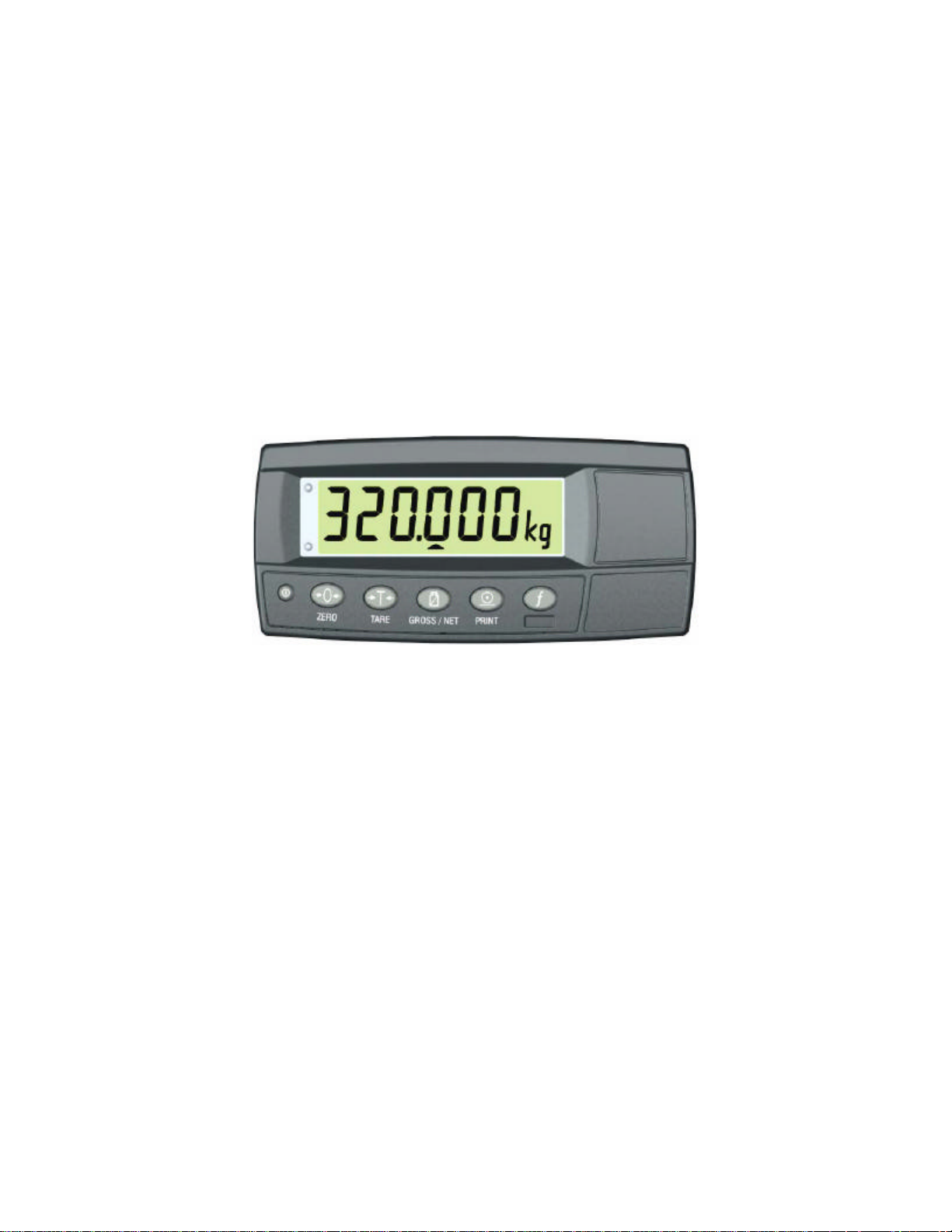
3.1 User Interface Display and Controls
3.2 Operation Keys
KEY DESCRIPTION
POWER: The <POWER> key is used to turn the instrument on and off.
• To initially turn the instrument ON: Press and hold the <POWER> key until the display starts
up.
• To turn the instrument OFF: Press and hold the <POWER> key for three seconds. The
instrument will display OFF followed by the three-second countdown.
Note: If the <POWER> key has been locked, the instrument cannot be turned off from the front
keypad.
• Battery Operation: When using batteries the backlight will automatically turn off to conserve
power after a short period of inactivity. A short press of the <POWER> key will turn the backlight on
again.
• Automatic Operation: The <POWER> key has a memory function associated with it. This means
that the state of the power setting is remembered even if external power is interrupted. It is
therefore possible to turn the instrument on in the safe knowledge that it will operate whenever
external power is available and will not need to be manually turn ed on again if the power is
interrupted.
ZERO: The <ZERO> key is used to perform a Zero adjustment on the scale display when an empty
scale has drifted away from a true zero reading.
ZERO
TARE
• The Zero adjustment is stored when power is removed and is re-used when next powered up.
• Long Press: When the indicator is set to Industrial mode a long press of the <ZERO> key will
remove any stored zero adjustment.
TARE: The <TARE> key is used to temporarily set the scale to zero (such as canceling the weight
of a carton before performing a filling operation). The display will show the Net weight and the Net
annunciator will be lit.
• The <TARE> key can operate in all modes (i.e. Industrial, OMIL and NTEP).
• The weight tared is deducted from the allowable range of the scale, reducing the maximum weight
that can be displayed.
• The Tare adjustment is stored when power is removed and is re-used when next powered up.
GROSS/NET: The <GROSS/NET> key toggles the weight display between the Gross weight and
GROSS/NET
CF 145 DFI 250 2 Rev 1.0 003R-619-100
the Net weight (provided that a Tare has previously been acquired using the <TARE> key).
Page 5

PRINT: The <PRINT> key will trigger an output of the current weight reading if a printer or computer
has been attached to the instrument and the manual print function has been selected.
PRINT
Description
• The PRINT prompt is displayed while waiting for the printer to accept data.
• If the printer is offline the PRINT prompt will remain for a maximum of 10 seconds before the
operation is cancelled.
• Each weight printed is automatically added to an internal total weight.
• Long Press: A long press of the <PRINT> key will print the total. The total weight is then cleared
automatically.
FUNCTION: The <FUNCTION> key is program mable to suit customer requirements. A label
identifying the special function will be attached. Refer to Special Function page 10 for details of the
available functions.
• Long Press: A long press of the <FUNCTION> key may be used for certain functions depending
on the primary function of the key.
3.3 Stability Considerations
Once a <ZERO> , <TARE> or <PRINT> key is pressed, the unit waits for a stable valid reading before performing
the associated operation. If the weight readings remain unstable or invalid due to some diagnostic error for longer
than 10 seconds, the operation is cancelled and the STABLE ERROR message is displayed.
3.4 Annunciators
SYMBOL NAME DESCRIPTION
ZERO Visible when the gross reading is within ± ¼ of a division of true zero.
NET Visible when the displayed reading represents Net weight.
MOTION Visible when the displayed reading is not stable.
OVER Visible when the setpoint weight is over the setpoint target.
UNDER Visible when the setpoint weight is under the setpoint target.
ZERO BAND
HOLD Visible when the displayed reading is held.
LOW
BATTERY
Visible when the displayed weight is within the zero 'dead' band setting. (The zero
band symbol shows near the top right corner of the display.)
Visible when battery voltage is too low and batteries need replacing or recharging.
(The low battery symbol shows in the top right corner of the display.)
4.0 BASIC WEIGHING
4.1 Normal Weighing
• Ensure instrument is On and Zero annunciator is lit.
• Place your item on the weigh platform.
• Read the weight display.
4.2 Using Tare
• The indicator displays zero with Zero annunciator lit.
• Place the container on the weigh platform.
• Press the <TARE> key.
• The indicator will show the displayed zero weight and the Net annunciator will be lit.
• Fill the container to the required weight.
• Press the <GROSS/NET> key to toggle between the Net weight and the Gross (total) weight.
CF 145 DFI 250 3 Rev 1.0 003R-619-100
Page 6

5.0 SPECIAL FUNCTION S
5.1 Testing the Display
• Press the <TEST> key to clear the display then show all segments of the display then clear the display
again before returning to normal operation.
5.2 Counting
• Place the container on the weigh platform and press <TARE> if required.
TARE
• Place the sample pieces to be counted on the weigh platform.
• Press and hold the <COUNT> key for two seconds. The default number of pieces in the sample will be
displayed.
• Use the <GROSS/NET> and <PRINT> keys to alter the number of pieces.
and
• Press <COUNT>. The current sample will be stored against the entered pieces. The letter p (for
pieces) displays when in counts display.
• Press the <COUNT> key to toggle between the weight display and the counts display.
• If printing is enabled the sample quantity and weight will be printed.
5.3 Units Switching (kg / lb)
• Press the <UNITS> key to switch the display between kilograms and pounds.
• Printing and serial communications will use the units displayed (either lb or kg).
5.4 Hold
• Press the <HOLD> key to hold the displayed weight at its current weight.
• The Hold annunciator will be lit.
• Press the <HOLD> key again to release the weight reading and return the display to normal weighing.
• All printouts that print the displayed weight will use the held weight reading if it is currently being displayed.
5.5 Peak Hold
• Press the <PEAK> key to show the largest absolute weight, either positive or negative (eg. - 30 is
larger than 25). The instrument compares the current weight reading with the stored peak and updates
the peak reading whenever a larger weight is detected.
• The Hold annunciator will be lit.
• Press the <PEAK> key to toggle between the current weight and the peak weight.
• When displaying the peak weight the Hold annunciator will be lit.
CF 145 DFI 250 4 Rev 1.0 003R-619-100
Page 7

• When displaying the peak weight, press and hold the <PEAK> key for two seconds to clear the peak
value and reset back to 0 (zero).
• All printouts that print the displayed weight will use the held weight reading if it is currently being displayed.
5.6 Live Weighing
• Press and hold the <LIVE WT> key to switch between normal weighing and live weight mode. The
display will briefly show NORMAL or LIVE.WT.
• Note: During normal weighing, this key operates exactly like a manual <HOLD> key.
• When in Live-Weight mode and while the Net weight is within the zero 'dead' band, the instrument shows the
current weight.
• Press the <TARE> or <ZERO> key to clear any residual weight and return the scale to
the zero state.
• Move the animal onto the weigh platform.
• Once the weight moves outside the zero 'dead' band the instrument begins to calculate a long-term average that
compensates for any movement in the mass. The instrument flashes the Hold annunciator and shows the current
average value.
• The Hold annunciator is steady when the final sample weight is shown on the display.
• Press the <LIVE.WT> key to force the sample to be recalculated.
• Once the animal is removed, the instrument automatically clears the previous reading ready for the next animal.
TARE or
ZERO
5.7 Showing Totals
• The <PRINT> key is used not only to print the current weight but also to add that weight to the
current total.
• When the <TOTAL> key is pressed, the indicator displays COUNT followed by the number of items
in the total.
• After this the indicator displays TOTAL followed by the current total weight.
• If the total weight is too large to display in six digits, the weight is shown in two sections labeled with the upper six
digits displayed before the lower six digits.
• Press and hold the <PRINT> key to cause the total accumulated weight to be printed and then
cleared.
CF 145 DFI 250 5 Rev 1.0 003R-619-100
Page 8

6.0 ERROR MESSAGES
6.1. Weighing Errors
Error Description Resolution
(U - - - - -)
(O - - - - -)
(ZERO)
(ERROR)
(STABLE)
(ERROR)
The weight is below the minimum allowable
weight reading.
The weight is above the maximum allowable
weight reading. Warning – overloading may
damage mechanical scale elements.
The weight reading is beyond the limit set for
Zero operation. The operation of the <ZERO>
key is limited in the setup during installation. The
indicator cannot be zeroed at this weight.
Scale motion has prevented a <ZERO>,
<TARE> or <PRINT> operation from occurring
on command.
6.2 Setup and Calibration Errors
Error Description Resolution
Access Full Setup to edit the item. (ENTRY)
Turn the instrument off. When the instrument is turned back
on, enter the correct passcode to access setup.
Incorrect linearization point entered (must be between zero
and full scale).
Re-enter the calibration point. Points must be spaced by at
least 2% of full scale from each other.
Check the resolution (count-by) and capacity settings.
Check the resolution (count-by) and capacity settings.
Incorrect span weight entered (must be between zero and
full scale). Scale wiring incorrect. Wrong load cell capacity
(too large). Wrong or no calibration weight added to scale.
Incorrect span wei ght entered (must be between zero and
full scale). Scale wiring incorrect. Load cell capacity too small
for application.
Scale wiring incorrect.
Remove all weight from scale. Scale wiring incorrect.
(DENIED)
(LIN.PT)
(LO)
(PT.TOO)
(CLOSE)
(RES)
(LO)
(RES)
(HIGH)
(SPAN)
(LO)
(SPAN)
(HI)
(ZERO)
(LO)
(ZERO)
(HI)
The instrument may be in Safe Setup
and an item that needs Full Setup has
been selected for editing.
When accessing setup, more than
three attempts have been made with
the incorrect passcode.
An attempt has been made to place a
linearization point below zero.
An attempt has been made to place a
calibration point too close to an
existing calibration point.
The scale build is configured for less
than 100 graduations.
The scale build is configured for more
than 30,000 graduations.
The load cell signal range (span) is too
small for these settings.
The load cell signal range (span) is too
large for these settings.
An attempt has been made to calibrate
zero below - 2mV/V.
An attempt has been made to calibrate
zero above +2mV/V.
6.3 Diagnostic Errors
Increase the weight or decrease the minimum
allowable weight reading.
Check the condition of load cell connections.
Check for damaged load cell.
Increase the Zero Range (OPTION: Z.RANGE)
or use the <TARE> key instead.
Try the operation again once the scale is stable.
• Check: Service personnel can check this item on site.
• Return for Service: The instrument must be returned to Cooper Instruments for factory service.
Error Description Resolution
(E0001) The power supply voltage is too low. Check supply
(E0002) The power supply voltage is too high. Check scale / cables
CF 145 DFI 250 6 Rev 1.0 003R-619-100
Page 9

(E0010) The temperature is outside of allowable limits. Check location
(E0020)
(E0100) The digital setup information has been lost. Re-enter setup
(E0200) The calibration information has been lost. Re-calibrate
(E0300) All setup information has been lost. Enter setup and calibrate
(E0400) The factory information has been lost. Return for Service
(E0800) The EEPROM memory storage chip has failed. Return for Service
(E2000)
(E4000) The battery backed RAM data has lost data. Re-enter setup
(E8000) The FLASH program memory is incorrect. Return for Service
The E type error messages are additive. For example, if instrument is running off batteries and the temperature
drops, the battery voltage may be too low. The resulting error messages will be E0011 (0001 + 0010). The numbers
add in hexadecimal as follows:
Scale build is incorrect. The number of graduations has been
set too low or too high.
ADC Out of Range Error. This may be caused from a broken
load cell cabl e.
1 - 2 - 3 - 4 - 5 - 6 - 7 - 8 - 9 - A - B - C - D - E - F
(For example, 2 + 4 = 6, or 4 + 8 = C)
Fix up scale build
Check BUILD:CABLE setting. Check
load cell cable, wiring, etc.
7.0 WARRANTY REPAIR POLI CY
Limited Warranty on Products
Any Cooper Instruments product which, under normal operating conditions, proves defective in material or in
workmanship within one year of the date of shipment by Cooper will be repaired or replaced free of charge provided
that a return material authorization is obtained from Cooper and the defective product is sent, transportation
charges prepaid, with notice of the defect, and it is established that the product has been properly installed,
maintained, and operated within the limits of rated and normal usage. Replacement or repaired product will be
shipped F.O.B. from our plant. The terms of this warranty do not extend to any product or part thereof which, under
normal usage, has an inherently shorter useful life than one year. The replacement warranty detailed here is the
buyer’s exclusive remedy, and will satisfy all obligations of Cooper whether based on contract, negligence, or
otherwise. Cooper is not responsible for any incidental or consequential loss or damage which might result from a
failure of any and all other warranties, express or implied, including implied warranty of merchantability or fitness for
particular purpose. Any unauthorized disassembly or attempt to repair voids this warranty.
Obtaining Service under Warranty
Advance authorization is required prior to the return to Cooper Instruments. Before returning the item, contact the
Repair Department c/o Cooper Instruments at (540 ) 349-4746 for a Return Material Authorization number.
Shipment to Cooper shall be at buyer’s expense and repaired or replacement items will be shipped F.O.B. from our
plant in Warrenton, Virginia. Non -verified problems or defects may be subject to a $100 evaluation charge. Please
return the original calibration data with the unit.
Repair Warranty
All repairs of Cooper products are warranted for a period of 90 days from date of shipment. This warranty applies
only to those items that were found defecti ve and repaired; it does not apply to products in which no defect was
found and returned as is or merely recalibrated. It may be possible for out -of-warranty products to be returned to
the exact original specifications or dimensions.
* Technical description of the defect: In order to properly repair a product, it is absolutely necessary for Cooper to
receive information specifying the reason the product is being returned. Specific test data, written observations on
the failure and the specific corrective action you require are needed.
CF 145 DFI 250 7 Rev 1.0 003R-619-100
 Loading...