

Page 1

DFI 2000
Process Monitor and
Control Instrument
User’s Guide
www.cooperinstruments.com
PH: 540-349-4746 • FAX: 540-347-4755
Page 2

CONTENTS
1.0 INTRODUCTION ...................................................................................................................4
1.1 System Overview ........................................................................................................................... 4
1.2 Process Monitoring Functions ..................................................................................................... 4
1.3 The Process Control Output Signals ........................................................................................... 6
1.4 Programmable Setpoints............................................................................................................... 6
1.5 The Analog Output......................................................................................................................... 7
1.6 Data Logging .................................................................................................................................. 7
1.7 Automatic Calibration.................................................................................................................... 7
1.8 Absolute and Relative Modes ....................................................................................................... 7
1.9 Scaling ............................................................................................................................................ 7
1.10 Units .............................................................................................................................................. 8
1.11 Menu Locking............................................................................................................................... 8
1.12 Automatic Power-Down............................................................................................................... 8
1.13 Manual Power-Down.................................................................................................................... 8
1.14 AC Outlet or Battery Operation................................................................................................... 8
1.15 Support for Third Party Transducers ......................................................................................... 8
2.0 BASIC OPERATION .............................................................................................................9
2.1 Initial Power-up .............................................................................................................................. 9
2.2 Key Definitions............................................................................................................................... 9
2.3 The Menu System......................................................................................................................... 10
2.4 Using the Track Function............................................................................................................ 12
2.5 Using the Peak Functions ........................................................................................................... 13
2.6 Using the Auto and Manual Record Functions ......................................................................... 13
3.0 APPLICATIONS ..................................................................................................................14
3.1 Monitoring Continuous Change ................................................................................................. 14
3.2 Recording Peak Readings........................................................................................................... 14
3.3 Uploading Logged Peak Readings to a Computer or Printer .................................................. 15
3.4 Digitizing a Force-Time Curve .................................................................................................... 16
3.5 Using the Output Signals ............................................................................................................ 17
3.6 Programming Third Party Sensors.............................................................................................19
4.0 APPENDIX ..........................................................................................................................21
4.1 Connecting the DFI 2000 ............................................................................................................. 21
5.0 BATTERY REPLACEMENT................................................................................................ 22
5.1 Specifications............................................................................................................................... 22
6.0 WARRANTY REPAIR POLICY ...........................................................................................23
CF 13 iii ver. 7.2 FEB. 99
Page 3

1.0 INTRODUCTION
1.1 System Overview
The DFI 2000 is a multi-function Process Monitor and Control instrument, designed to operate with Cooper auto-id
transducers. The DFI 2000 has been enhanced to support torque sensors with quadature encoders. This
functionality is supported via AutoID and third party sensor programming. Version 7.2 will have an encoder chip and
new software installed. For easy verification of version 7.2, if a torque sensor with encoder is attached at power up,
an >E= will be displayed at the end of the line of the sensor data.
Additional features of the DFI 2000 are additional options under the menu items:
• Settings
• Transducer
The DFI 2000 is a portable instrument, and comes with the following:
• carrying case,
• shoulder strap,
• 12 V 600 mA power supply, and
• this manual.
If any of these items are missing, call Cooper Instruments at (800) 344-3921.
Features
The DFI 2000 features:
• six process monitoring functions, including:
o a continuous tracking function,
o 3 peak logging functions,
o 2 waveform recording functions (with multiple record rates),
• 3 process control output signals (for High, Low and Target occurrences),
• programmable setpoints for Threshold, Target, High and Low Limits,
• analog output,
• storage capability for up to 8,000 peak readings,
• 4 [peak] data logging operations,
• automatic calibration with Cooper’s strain gage based auto-id sensors,
• collects absolute values or values relative to a user defined zero point,
• scaling adjustment for transducers,
• multiple unit capability and automatic units conversion,
• menu locking,
• automatic power-down,
• rechargeable Ni-Cad batteries, and
• support for third party transducers.
1.2 Process Monitoring Functions
The DFI 2000 provides six process monitoring functions:
• Track,
• - Peak,
• + Peak,
• +/- Peak,
• Auto Record, and
• Manual Record.
Track is always available by pressing the TRACK button. The FUNC button can be programmed for any one of the
other five functions.
Track
Track provides continuous monitoring of a process. The instrument takes readings at 5 kHz (without an encoder),
2kHz (with an encoder in >deg= mode), or 20Hz (with an encoder in >rpm= mode) averages them, and updates the
CF 13 4 ver. 7.2 FEB. 99
Page 4
display 4 times/second. In the Track function, re-taring zeros the encoder. (Track is designed for slowly changing
processes.)
Peak
The Peak functions (-, +, +/-) sample data at a rate of 5 kHz. However, if the encoder is enabled and in >deg=
mode, the sample rate is 2kHz. If the encoder is in >rpm= mode, the sample rate is 20 kHz.
In all Peak functions when readings drop below 80% of the user-defined Threshold Value, the PMAC engages a 100
msec timer. If readings rise above threshold within that time, the process cycle continues. If not, the process cycle
ends and readings are evaluated with respect to the limits. This timer is reset every time readings drop below
threshold.
Record
All functions except Manual record enable the encoder at the threshold for >deg= mode, or immediately for >rpm=
mode. Manual record enables the encoder at the manual trigger for >deg= mode. The Auto and Manual Record
functions have programmable record rates.
The >Record= functions will only allow 10kHz and 5kHz rates without an encoder. All other rates are allowed with an
encoder. The encoder is sampled at the record rate for Adeg@ or >rpm= mode.
The >Record= and Peak functions are limited to a total of 8,000 readings with or without an encoder.
+ Peak
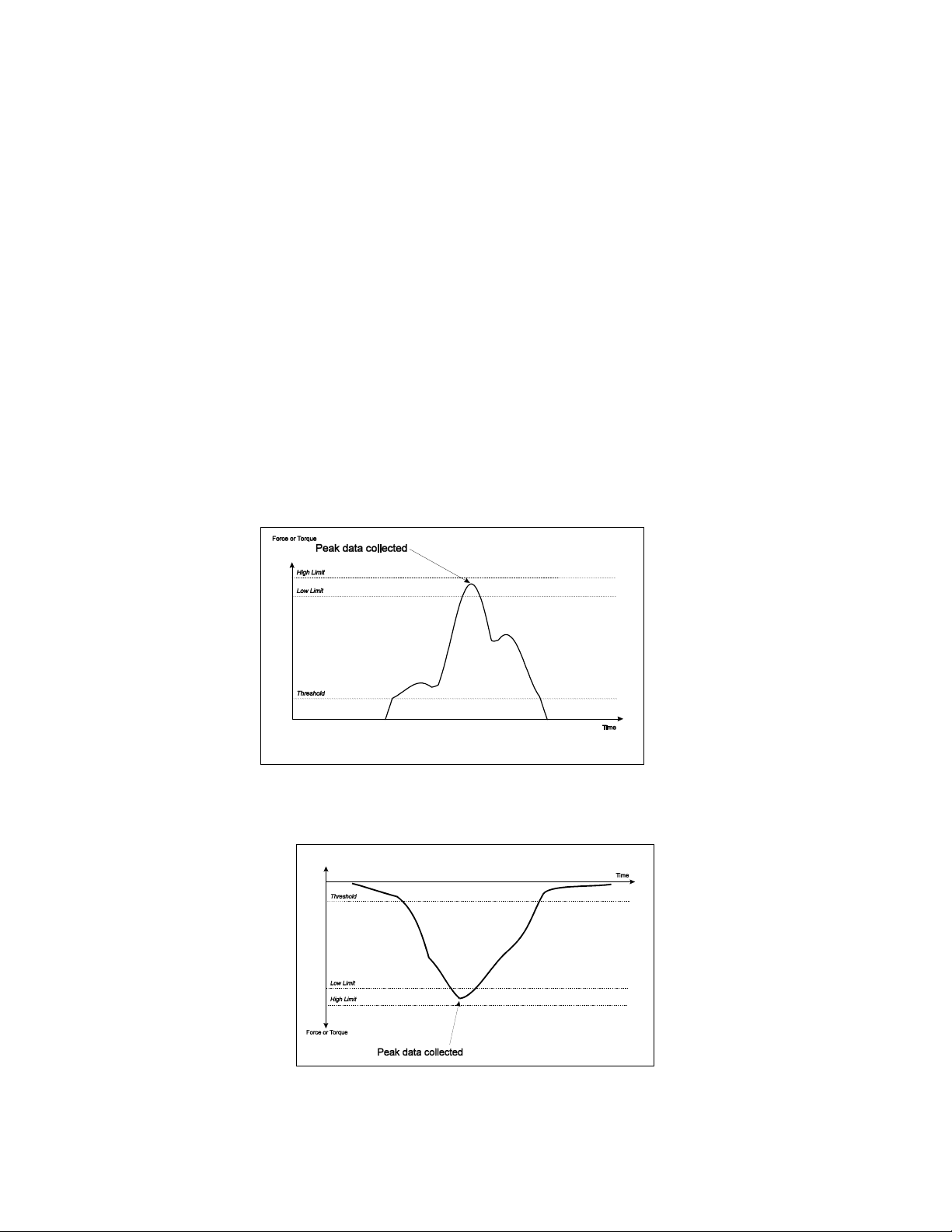
+Peak collects, displays and evaluates the highest [positive] peak value above the user-defined threshold.
+ Peak ignores negative values.
-Peak
-Peak collects, displays and evaluates the lowest [negative] peak value below the user-defined threshold.
- Peak ignores positive values.
CF 13 5 ver. 7.2 FEB. 99
Page 5
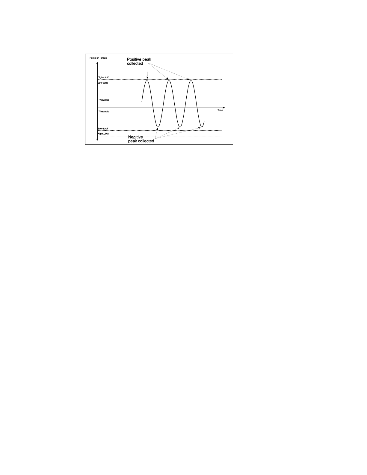
+/- Peak
+/- Peak collects, displays and evaluates the greatest positive or negative values.
All setpoints are symmetrical about the x-axis.
Note: The DFI 2000 collects only one reading per process cycle. If readings rise from negative to positive values
within a process cycle, (this happens if readings are between the positive and negative Threshold for less than 100
msec.) the instrument records the peak with the greatest absolute value.
Auto and Manual Waveform Recording
Auto and Manual waveform recording are data recording functions that digitize incoming signals. Up to 16,000 data
points can be stored. Neither function displays readings, or evaluates them with regard to the limits. The following
update rates are available: 10, 5, 2, and 1 kHz, and 500, 200, 100, 50, 20, 10, 5, 2, and 1 Hz. For the 10 kHz*
scanning rate, data is sampled and stored; the instrument does not average the data. For the 5 kHz* scanning rate,
data is sampled at 5 kHz and continuously averaged to store readings. For each of the other scanning rates, data is
sampled at a rate of 6 kHz and continuously averaged to store readings at the selected rate.
*10kHz and 5kHz rates are only available when the encoder is not used.
1.3 The Process Control Output Signals
The DFI 2000 has three open collector, process control output signals:
• High Condition Signal,
• Low Condition Signal, and
• Target Signal.
When a Peak function is selected, the Target Signal is a real-time signal transmitted when a reading equal to, or
greater than, the Target Value is detected. The High Condition and Low Condition Signals are post-process signals
transmitted after readings drop below threshold, and the peak value is evaluated. These readings are also evaluated
with respect to the encoder limits and target value.
When Track is selected, all signals are transmitted in real-time. When a waveform recording function is selected, all
signals are disabled.
All three signals are TTL compatible and are transmitted through the I/O connector on the back of the unit. (See the
chapter on Connecting the PMAC for more information.)
1.4 Programmable Setpoints
When each type of sensor (i.e., force, torque or displacement) is first connected to the DFI, the instrument sets all of
the setpoints to their default values.
Threshold Value = 5% of sensor's Full Scale
High Limit = sensor's Full Scale
Low Limit = 5% of sensor's Full Scale
CF 13 6 ver. 7.2 FEB. 99
Page 6

Target Value = sensor's Full Scale
Each of these values may be changed by the operator. (See the Basic Operation and Applications chapters.) The
DFI 2000 retains the most recent setpoint values for all three types of sensors; i.e., when you disconnect a torque
sensor and connect a force sensor, the setpoints are reset to the values used with the last force sensor connected
to the instrument.
1.5 The Analog Output
The analog output is the signal from the transducer, amplified and relayed through a low pass filter. The instrument
provides an excitation of 7 V. The amplifier has a gain factor of 76 for a nominal output of 1 V at 2 mV/V. This signal
is transmitted through the I/O connector. (See the Appendix for wiring diagrams.)
1.6 Data Logging
The peak functions log all peak values automatically. The DFI 2000 provides for:
• viewing [peak] readings on the DFI 2000 screen (one at a time),
• uploading the readings to a PC
• transmitting the readings directly to a serial printer, or
• erasing the readings.
The DFI 2000 can store up to 8,000 [maximum] peak readings.
Note: The data is stored in blocks, and each block contains a header. Each time you change transducer types or
units, the instrument must store an additional heading which reduces the memory available for storing peak values.
Leaving a waveform stored in memory will also reduce the memory available for storing peak values.
No data logging occurs when the Track or waveform recording functions are selected. Data collected by the
waveform recording functions must be uploaded to a PC or erased. It can not be viewed on the DFI 2000 screen.
Data Transmission
The DFI 2000 transmits data in ASCII format with the following parameters:
Baud Rate = 9600
Parity = None
Data Bits = 8
Stop Bits = 1
Flow Control = None or Xon/Xoff
1.7 Automatic Calibration
The DFI 2000 is designed to support Cooper’s auto-id sensors. Cooper’s auto-id sensors are equipped with an
EPROM that stores the sensor's Full Scale value, the mV/V output, and engineering units. The DFI 2000
automatically reads these values when:
• the sensor is initially connected,
• when the instrument is powered up, and
• when the operator exits the menu structure.
The DFI 2000 automatically recalibrates to the sensor when it detects a change in these values.
1.8 Absolute and Relative Modes
The DFI 2000 uses an internal reference bridge to define absolute zero. In Absolute mode, readings are taken with
respect to this value. In Relative mode readings are taken with respect to a tare value from the transducer.
Important: When using Absolute mode, it is important that the user-defined threshold be at least 25% greater than
sensor's offset from zero.
1.9 Scaling
The DFI 2000 multiplies all new readings by the scaling factor before storing or displaying the data. Changing the
CF 13 7 ver. 7.2 FEB. 99
Page 7

scale factor does not affect previously stored readings. With a scale factor of 1.0 the instrument stores and displays
readings exactly as taken.
The instrument retains the most recent scale factor for all three types of sensors. (Same as the setpoints for the limit
values.)
1.10 Units
The DFI 2000 provides automatic unit conversion. The Full Scale value for all Cooper’s auto-id sensors are
specified in engineering units. When the operator selects a different set of units, the DFI 2000 converts the Full
Scale value, the High and Low limits, the Threshold and Target values, and all readings [taken from that point on] to
the new units. The following units are available:
Force: oz, lbs, Tons, g, kg, N
Torque: inoz, inlbs, ftlbs, kgcm, kgm, NM
Displacement: mils, in, mm, cm
Absolute numbers: None
Note: The DFI 2000 will only allow the operator to select units that are consistent with the type of transducer
connected, i.e., torque units for a torque transducer.
1.11 Menu Locking
All of the above mentioned features are accessed through the DFI 2000's menu system. Each of the four menus
(see the Basic Operations chapter) can be locked to prevent accidental changes.
1.12 Automatic Power-Down
The DFI 2000 will automatically power-down 12 minutes after the transducer is disconnected (unless the instrument
is in the menu system).
1.13 Manual Power-Down
To power-down the instrument manually, hold the OFF key for five seconds and release.
1.14 AC Outlet or Battery Operation
The DFI 2000 can operate from an AC outlet or from the internal Ni-Cad batteries. When completely charged, the
batteries should last for approx. 8 hrs.
To completely charge the batteries, the instrument must be plugged into an outlet for 16 hrs. There is no danger of
over-charging the batteries if left plugged in for longer than 16 hrs.
Note: If the instrument is left charging for "several weeks", the batteries' charge life will be severely diminished. (This
is a property of all Ni-Cad rechargeable batteries.) Cooper recommends completely discharging the batteries on
occasion to maintain their charge life.
Note: When shipped from Cooper’s factory, the batteries will be completely discharged.
1.15 Support for Third Party Transducers
Third party transducers may be connected to the DFI 2000 using a standard 15 pin D-sub connector, or Cooper’s
auto-id connector (Model 90144). In either case, when the sensor is first connected to the DFI 2000, the instrument
will prompt you for the sensor's calibration data. (See the Applications chapter).
When using sensors with a standard 15 pin connector, the data is stored in RAM. So that it is not necessary to
reenter the calibration data if the sensor is disconnected and immediately reconnected. But it must be reentered if
another sensor is connected in the interim. These sensors are identified as "Raw".
When using sensors with Cooper's auto-id connector, the instrument writes the calibration data to the connector's
CF 13 8 ver. 7.2 FEB. 99
Page 8

EPROM; and retrieves it each time the sensor is connected. The DFI 2000 programs these connectors with the
transducer type, Full Scale value, the mV/V output, and the engineering units. This provides automatic calibration
every time the sensor is connected to the instrument. These sensors are identified as "Cus".
Note: Transducers that are programmed at Cooper Instruments factory include a "write protect" code. The DFI 2000
will never overwrite the values stored in these connectors.
2.0 BASIC OPERATION
2.1 Initial Power-up
Press any key to turn on the DFI 2000.
Initial Self Checks
On powering up, the instrument briefly displays "PMAC 2000 V7.2", indicating the software revision number.
If no transducer is connected, the DFI 2000 displays, "Check transducer".
Once a transducer is connected, the instrument displays:
"SDI 10 lb",
"Relative Mode or Absolute Mode
Counting . . ."
The first message is a description of the transducer.
ID NAME
FULL SCALE VALUE
SDI 10 NM
Note: When a third party transducer is connected, "Cus" or "Raw" will replace "SDI". The second message indicates
if the instrument is in Absolute or Relative Mode. The last message is displayed while the instrument determines
how much RAM is currently available for storing new readings.
Ready to collect data
When the instrument is ready to collect data it displays one of the following messages:
"R0000 Ready" - if a peak function was selected and there is no data stored,
"R0001 202.0lb" - if a peak function was selected and there is data stored,
"Ready to record" - for auto trigger recording, or
"Accept to record" - for manual trigger recording.
Note: If the screen goes blank, the instrument is set to Auto-record and readings may already be above the
threshold. Press ESC to cancel the data sampling.
2.2 Key Definitions
UNITS
The DFI 2000 has four keys. Each key has multiple functions, and is labeled with
its main function and its menu-navigation function.
CF 13 9 ver. 7.2 FEB. 99
Page 9

The main functions are as follows:
Enters the menu system.
Selects the Track function.
Programmable key-- can be set to select any one of the five following functions: +Peak, -Peak, +/-Peak, ARecord, or M-Record.
Hold for 5 sec. and release to turn off the DFI 2000. (The "OFF" feature is always available.)
Each key's additional functions are described in the following sections.
2.3 The Menu System
The DFI 2000 is configured through a menu system.
There are four menus:
1. Log operations,
2. Settings,
3. Transducer setup, and
4. Menu locking
You enter the menu system by pressing MENU
Note: The DFI 2000 does not collect data while in the menus.
The menu system is as follows:
Log Operations Settings Transducer setup* Menu locking
View log Func: <current> Type: <current> L-Menu: <current>
Upload log R-rate: <current> Unit: <current> S-Menu: <current>
Print log Unit: <current> FS: <current> T-Menu: <current>
Erase log ZMode: <current> mV/V: <current>
Thrshld: <current> EPPR: <current>
LLimit: <current> Write to AutoID
Target: <current>
HLimit: <current>
Scale: <current>
Emode: <current>
ELLimit: <current>
ETarget: <current>
EHLimit : <current>
Echo: <current>
*Note: The "Transducer setup" menu is only available when "Cus" or "Raw" sensors are connected to the
instrument. (i.e. no auto-id - See page 7.)
In the menu system, the keys perform the following functions:
Selects displayed menu items for change.
Scrolls through menu or submenu choices.
Accepts changes and exits submenu./ Performs displayed operation.
CF 13 10 ver. 7.2 FEB. 99
Page 10

Discards changes, exits submenu and returns to higher menu.
Log Operations Menu
To execute any log operations, press Accept. While uploading or printing, the DFI 2000 displays the data on screen as it is
sent; while erasing data, the DFI 2000 will display "Erasing". When Viewing Data the keys perform the following functions:
-No Function
Scrolls to the next reading.
Scrolls to the previous reading
Exits the subroutine and returns to the "Log Operations" submenu.
The “Erase log” command requires confirmation. To confirm the “Erase log” command, press Next and Accept.
Settings Menu
The "Settings" menu contains four multiple choice items:
Function, R-rate, Unit, and ZMode.
and nine numeric items:
Threshold, High Limit, Target, Low Limit, Scale, Encoder Low Limit, Encoder Target, Encoder High Limit, and
Echo.
When changing a multiple choice item:
Selects the currently displayed item for changing and enters the submenu containing the available choices.
Scrolls to the next available choice in a submenu.
Accepts the currently displayed item, and returns to the "Settings" menu.
Exits the submenu and returns to the "Settings" menu.
When changing numeric items:
Selects the currently displayed item for changing and accesses the numeric entry subroutine. Changes the
value of the current digit position.
Scrolls to the next digit.
Accepts the currently displayed value, and returns to the "Settings" menu.
Discards the new value./ Press twice to exit the subroutine and return to the Settings" menu.
See the Applications Chapter for examples of setting up the DFI 2000 for various tasks.
Transducer Settings Menu
The "Transducer settings" menu is for entering calibration data into the Model 90144 connector, and for changing the data
for raw sensors. This menu is only available when a Model 90144 or a standard 15 pin connector is connected to the DFI,
and is never available when a Cooper sensor is connected to the instrument.
This menu contains three multiple choice items:
transducer type (force, torque or displacement),
units,
encoder (y/n),
three numeric items:
full scale value,
mV/V output, and
encoder pulses per rev (EPPR).
CF 13 11 ver. 7.2 FEB. 99
Page 11

and the command "Write to AutoID".
The keys work the same in this menu as they do in the "Settings" menu. And the "Write to AutoID" requires
confirmation (the same as the "Erase Log" command.)
Note: The "Transducer settings" comes up automatically when a connector [that has never been programmed] is
first connected to the instrument. At that time it is not necessary to press the Next key to go from one menu item to
the next. But when accessing this menu from the menu system you must press the Next key to go from one menu
item to the next.
Menu Locking
The Locking Menu is used to protect menu selections from accidental change. Each of the three submenus can be
individually locked.
The DFI 2000 requires a password to access the "Menu Locking" menu. The password is "290". (See the section on
entering numeric values above for further instructions.)
When a menu is locked, you will be able to enter it and view the currently selected item or values, but you will not be
able to change them.
When the menus are locked:
• The "Settings" and "Transducer setup" submenus, Next will scroll through the values, but Change and
Accept will not function. Esc will exit the submenu.
• In the "Log operations" submenu, the View Data, Upload Data, and Print Data will function normally, but you
will not be able to Erase Data. Esc will exit the submenu.
If you attempt to change a locked item, the DFI 2000 will respond by flashing the message "*** LOCKED ***" for
one second.
2.4 Using the Track Function
When the Track function is selected, the instrument displays:
The keys perform the following functions:
Enters the menu system.
Tares the sensor.
Selects the programmed function.
Tares the sensor.
Note: The DFI 2000 does not log readings when the Track function is selected. With the encoder function, no limits
are displayed with the angle function.
CF 13 12 ver. 7.2 FEB. 99
Page 12

2.5 Using the Peak Functions
When any of the three peak functions are selected, the instrument displays the reading number, the most recent
peak reading, and the units as shown:
Readings are logged, and the display is updated after each loading cycle; i.e., after readings rise above and then
drop below the Threshold Value.
The keys perform the following functions:
Enters the menu system.
Selects the Track function
Will decrement the reading number, allowing the last reading to be re-taken.
Toggles between Absolute and Relative Modes.
2.6 Using the Auto and Manual Record Functions
The Auto and Manual Record functions are identical except for the initial trigger. The Auto Record function uses the
Threshold Value as its signal to begin recording data. The Manual Record function requires pressing the Accept key
to begin recording data.
The DFI 2000 stops recording when either of the following occur:
• the memory is full, or
• the ESC key is pressed.
Before recording data, the instrument displays "Ready to record". While the instrument is recording, the screen
will be blank and the green indicator light will flash at the recording rate. (Refer to the section on the menu system
for information on selecting the scanning rate.)
When the instrument is done recording, it displays "Accept to upload". Pressing the Accept key uploads the
data to a computer via the RS-232 port.
Only one digitized curve can be stored in memory at a time. The instrument retains all data when you enter the
menu system or turn off the DFI 2000. Recorded data must be manually erased.
To Erase data:
1. Press ESC to initiate the "Erase data" command.
2. Press Next to scroll to "Yes".
3. Press Accept to confirm the "Erase data" command.
The keys perform the following functions:
Enters the menu system.
Selects the Track function. /Scrolls from "No" to "Yes" when confirming the "Erase data" command.
CF 13 13 ver. 7.2 FEB. 99
Page 13

Begins recording in Manual. /Uploads data. /Confirms the Erase command.
Stops data recording. /Initiates "Erase Data" command.
3.0 APPLICATIONS
3.1 Monitoring Continuous Change
Use the Track function to monitor continuous changes. Select the Track function by pressing the TRACK key.
(Outside of the menus.) The instrument will monitor the sensor and update the display four times per second (4 Hz).
Readings may be taken in either Relative or Absolute mode. In Relative mode the instrument tares the sensor and
readings are relative to the sensor's offset. In Absolute mode, readings are taken with respect to absolute zero;
defined by the instrument's internal reference bridge.
3.2 Recording Peak Readings
The DFI 2000 can collect and store peak readings from any force, torque or displacement. The instrument can also
automatically convert readings from one unit to another as the readings are collected. (The instrument will not
convert the units of readings already stored.)
Example
Suppose you have a 50 kg load cell (with a 0.05 kg offset) and you want to record peak readings in pounds.
To set up the DFI 2000, do the following:
Step Action Instrument Displays:
DFI 2000 V7.2
Transducer check
1 Connect the sensor and power-up the instrument.
Enter the menu system.
SDI 50 kg
Absolute mode
A0000 Ready
2
Assign a Peak function to the FUNC key.
3
4
5
6
7
Select the units.
8
9
CF 13 14 ver. 7.2 FEB. 99
to enter the menu system.
to scroll to the "Settings" menu.
to enter the "Settings" menu.
to enter the "Function" submenu.
(twice) to scroll through the function
choices.
to select the currently displayed function.
(twice) to scroll to the "Units" submenu.
to enter the "Units" submenu.
Log operations
Settings
Func: +peak
Indicates the current function.
New Fn: +peak
New Fn: -peak
New Fn: +/-peak
Func: +/-peak
Unit: kg
New Unit: kg
Page 14

Step Action Instrument Displays:
10
11
12
[Optional] Erase any previously recorded data.
13
14
15
16
17
18
Exit the menu system.
19
The instrument is now set up to collect peak reading.
(4 times) to scroll to lbs.
to select the displayed units.
to exit the "Settings" menu.
(twice if using an SDI sensor, three times
if using a third party sensor) to scroll to
the "Log operations" menu.
to enter the "log operations" menu.
(3 times) to scroll to "Erase log".
to erase the log.
and
to confirm the erase log command.
To exit the "Log operations" menu.
to exit the menu system.
New Unit: lb
Unit: lb
Settings
Log operations
View log
Erase log
Erase log: No
The instrument asks for confirmation.
Erase log: Yes
Erasing
Erase log
Note: if the log only contains a few
entries, "Erasing" may be displayed to
quickly to be seen.
Log operations
Transducer check
A0000 Ready
3.3 Uploading Logged Peak Readings to a Computer or Printer
To calculate any statistics from collected peak data, it is necessary to upload the collected data to a computer. The
readings may also be sent directly to a printer.
There are three steps to uploading the data:
Step 1: Connect the DFI to either the computer or the printer. Use the RS-232 port on the back of the DFI 2000,
and the serial port on the computer or printer.
To connect to a printer, use a standard IBM serial printer cable.
To connect to a PC, use a standard IBM null modem cable.
Step 2: Prepare the PC to receive the data.
i. Launch a terminal emulation application such as Windows Terminal or Hyperterminal.
ii. Set the communications settings to:
Baud Rate = 9600
Parity = None
Data Bits = 8
Stop Bits = 1
Flow Control = None
Note: Since data is in raw ASCII format, it is not necessary to set the terminal emulation.
iii. Select "Receive Text File" from the data transfer options.
CF 13 15 ver. 7.2 FEB. 99
Page 15

You will be prompted for a file name. (Depending on the program, this may occur before or after the
data transfer.) All the data transmitted to the computer will be stored in this file.
iv. Enter a file name.
Step 3: Upload the data.
To upload peak readings to PC do the following:
Step Action Instrument Displays:
Enter the menu system.
1
2
3
4
[Optional] Erase Readings.
Note: Peak readings are not automatically erased, and can be downloaded to a computer or printer as many times
as desired.
5
6
7
8
Exit menu system.
9
To enter the menu system.
to enter the "Log
operations" menu.
(once) to scroll to "Upload
Log."
Or
(twice) to scroll to "Print
Log".
to upload or print the data.
to scroll to "Erase Log".
to erase the peak readings.
and
to confirm "Erase log"
command.
to exit "Log operations"
menu.
to exit the menu system
Log operations
View log
Upload log
or
Print log
The instrument will scroll through the readings as it uploads or prints
them.
Note: Uploading is faster than printing.
Erase log
Erase log: No
The instrument asks for confirmation.
Erase log: Yes
Erasing
Erase Log
Note: if the log only contains a few entries, "Erasing" may be
displayed to quickly to be seen.
Log operations
Transducer Check
R0000 Ready
3.4 Digitizing a Force-Time Curve
The DFI 2000 provides two functions for digitizing waveforms, the A-record function and the M-record function. To
capture a force-time curve with the M-record function, follow this procedure:
To set up the DFI 2000:
Step Action Instrument Displays:
DFI 2000 V7.2
Transducer Check
1 Connect the sensor and power-up the instrument.
Enter the menu system.
CF 13 16 ver. 7.2 FEB. 99
SDI 50 kg
Absolute mode
A0000 Ready
Page 16

Step Action Instrument Displays:
2
Assign a record function to the FUNC key.
3
4
5
6
7
Select the Recording Rate
8
9
10
11
to enter the menu system.
to scroll to the "Settings" menu.
to enter the "Settings" menu.
to enter the "Function" submenu.
to scroll to the desired function.
(In this case M-record)
to assign the displayed function to the FUNC key.
to scroll to "R-rate".
to enter the "R-rate" submenu.
to scroll to the desired recording rate. (In this case, 500Hz.)
to select the displayed recording rate
Log operations
Settings
Func: +/-peak
New Fn: +/-peak
New Fn: M-record
Func: M-record
R-rate: 10kHz
New rate: 10kHz
New rate: 500Hz
R-rate: 500Hz
12
Exit the menu system.
13
To record the force-time curve:
1. Press Accept to begin recording data.
2. Apply loads to the sensor.
3. When you are done applying loads, Press ESC to stop recording.
4. Press Accept to upload the data to a computer, or press ESC to erase the data. The instrument will ask for
confirmation. Press Next and Accept to confirm the erase command.
to exit the "Settings" menu
to exit the menu system.
Settings
Transducer check
Accept to record
3.5 Using the Output Signals
Example
Suppose you are fastening bolts with a nutrunner. The application requires that torque be between 90-100 in-lbs.
You want the PMAC to turn off the nutrunner when it detects a torque of 92 in-lbs; and you want to trigger an audible
alarm if the actual peak torque is not with in the specified range.
To set up the DFI 2000, do the following:
Step 1: Purchase a standard 9 pin D-sub male connector.
Step 2: Wire the connector to each of the alarms according to the following diagram.
CF 13 17 ver. 7.2 FEB. 99
Page 17

Note: In some cases you can connect the load directly to the instrument, but most cases do require a buffer as
shown.
Pins 1 and 5 are for the Target Signal; 6 and 7 are for the High Condition Signal; and 8 and 9 are for the Low
Condition Signal.
Step 3: Program the DFI to trigger the signals according to the following procedure:
Step Action Instrument Displays:
DFI 2000 V7.2
Connect the sensor and power-up the
1
instrument.
Transducer Check
SDI 50 kg
Absolute mode
A0000 Ready
Enter the menu system.
2
to enter the menu system.
Log operations
Assign a Peak function to the FUNC key.
3
4
to scroll to the "Settings" menu.
to enter the "Settings" menu.
Settings
Func: +peak
indicates the current function
5
6
7
to enter the "Function" submenu.
(twice) to scroll to the +/- peak
function.
To select the currently displayed
function.
New Fn: +peak
New Fn: -peak
New Fn: +/-peak
Func: +/-peak
Set the High and Low Limits for acceptable Peak Values; and the Target Value
8
9
10
11
12
13
CF 13 18 ver. 7.2 FEB. 99
(four times) to scroll to the Low
Limit
to change the Low Limit.
(11 times) to change the first digit
to "9".
to move to the second digit.
(twice) to change the second digit
to "0"
to scroll to the third digit.
LLimit:: 10.00
New LL: The underline indicates the
currently selected digit.
New LL: 9
New LL: 9_
New LL: 90
New LL: 90_
Page 18

Step Action Instrument Displays:
14
15
to change the third digit to ".".
to scroll to the fourth digit.
16 Repeat step 12.
17
18
19
20
21
22
Repeat Steps 10-18, entering 92.0 for the
Target Value.
Repeat Steps 9-17, entering 100.0 for the
High Limit.
to accept the displayed value.
to scroll to the Target Value.
to scroll to the High Limit.
to exit the "Settings" menu.
New LL: 90.
New LL: 90._
New LL: 90.0
LLimit: 90.0
Target: 200.0
Target: 92.0
HLimit: 200.0
HLimit: 100.0
Settings
Exit the menu system.
23
to exit the menu system.
A0000 Ready
To operate the instrument, apply torque to the sensor. When the instrument detects a torque equal to the Target
Value, it will send the Target Signal.
After each loading cycle is completed, the instrument will display the peak value and evaluate it relative to the High
and Low Limits. If the peak value falls above the High Limit, the instrument will send the High Condition Signal. If the
peak value falls below the Low Limit, the instrument will send the Low Condition Signal.
3.6 Programming Third Party Sensors
The DFI 2000 is designed for automatic calibration, and works best with a sensor that has our auto-id connector.
Fortunately, this connector may be attached to any manufacturer’s sensors. To configure another manufacturer’s
sensor to work with the DFI 2000, follow this procedure:
Step 1: Purchase a 15 pin D-sub connector or Cooper’s auto-id connector (Model 90144). To order the Model
90144, call 1 (800) 344-3921.
Step 2: Wire the connector to the sensor according to the following diagram:
Pins 9-15
Used for auto-id
Shield
- Excitati
- Sign
+ Sign
+ Excitati
This configuration may apply to both types of connectors.
CF 13 19 ver. 7.2 FEB. 99
5
4
3
2
1
Pins 6-8
Reserved for
furture use
Page 19

Step 3: Enter the sensor's calibration data into the auto-id connector with the DFI 2000.
Programming Example
Suppose you purchased a 200 in-lb rotary torque sensor with a 3.0 mV/V output from another manufacture, and
wanted to use it with the DFI 2000. After purchasing the connector and wiring it to the sensor, the calibration data
would be programmed into the auto-id connector in the following manner.
Step Action Instrument Displays:
1 Connect the sensor.
Custom AutoId
2 Power-up the instrument.
The instrument is informing you that there is not
calibration data stored in the sensor's connector.
3
4
5
6
7
8
9
to enter the transducer type menu. Type: force
to scroll through the sensor type submenu. Type: torque
to select the type of sensor displayed on the
screen, and enter the torque units submenu.
to scroll to the desired units. UNIT: inlb
to select the units and go to the Full Scale
Value.
(4 times) to change the first digit to "2". FS: 2
to move the cursor to the next digit, and FS: 2_
(twice) to change the digit to a "0". FS: 20
UNIT: inoz
FS: _
10 Repeat step 9 for the third digit. FS: 200
Repeat step 9, entering a decimal point for the fourth
11
digit.
FS: 200.
12 Repeat step 9, entering another "0". FS: 200.0
13
Repeat steps 8, 9 and 13 as necessary to enter the
14
mV/V value (in this case 3.0).
to enter the displayed value, and go to the
mV/V.
mV/V: _
Write to AutoID: No
18
and
to write the entered values to the auto-id
connector.
Write to AutoID: Yes
Transducer check
A0000 Ready
Note: When entering these values, note that they are stored in the DFI 2000's RAM until the operator selects "Write
to AutoID". Then they are written to the connector's EPROM. For proper calibration, it is important to enter all four
values at the same time.
CF 13 20 ver. 7.2 FEB. 99
Page 20

4.0 APPENDIX
4.1 Connecting the DFI 2000
There are four connectors on the back of the DFI 2000.
RS-232
The RS-232 connector is used to upload and print data.
DGND
TRANSM IT
RECEIVE
5
3
2
I/O
The I/O connector is used for:
• Analog Output,
• High Condition Signal,
• Low Condition Signal, and
• Target Signal.
LOW COND
LOW COND
HI COND
HI COND
TARGET
AOUT -
GND
AOUT +
TARGET
5
9
4
8
3
7
2
6
1
The analog output is a differential output across AOUT+ and AOUTB. It has a common mode voltage of 2.5 V with
respect to chassis ground. AOUTB is the reference and AOUT+ is driven positive or negative with respect to it. The
Output impedance of each is 620 Σ and the output voltage is +1.0 V nominal for 2 mV/V full scale sensor.
Wire the connections for the output signals according to the following diagram.
Pins: 1 and 5 Target Signal
2 and 6 High Condition Signal
CF 13 21 ver. 7.2 FEB. 99
Page 21

8 and 9 Low Condition Signal
AC Adapter/Charger (12 V dc)
The AC adapter is used to power the instrument, and charge the battery.
Transducer Wiring
12 V dc
GND
The standard 15-pin D sub Connector and the Model 90144
Connector are wired according to the diagram:
Ground
CW Trail
CW Lead
Shield
- Exc
- Sig
+ Sig
+ Exc
Pins 9-15 used
for auto-id
Pins 6-9
reserved for
future use
5.0 BATTERY REPLACEMENT
The DFI 2000 uses two types of batteries:
• a 9.6 V rechargeable Ni-Cad battery pack, and
• one 3 V lithium coin battery.
The rechargeable Ni-Cad batteries power the instrument when it is not plugged into a wall socket. If the "charge life"
of these batteries decreases significantly, or if the instrument refuses to work unless plugged into a wall socket, the
Ni-Cad batteries need to be replaced. This must be done at Cooper Instruments. Contact our service department at
1 (800) 344-3921 for shipping instructions.
The coin battery supplies power to the RAM when the instrument is turned off. This protects the collected data from
being erased when the instrument powers down. When this battery needs replacement, the instrument will display
the message: "Low Coin Battery". Replace this battery with a Duracell DL2025 or equivalent 3 V lithium coin battery.
5.1 Specifications
Sampling Rates
Peak and Track functions5 kHz
With encoder 2 kHz
Record functions
selectable up to 10 kHz
With encoder selectable up to 2 kHz
Frequency Response
Accuracy
(-3 dB) at 1000 Hz
max error = 0.05% of Full Scale
Sensor Interface
Max Input at Full Scale " 4.5 mV/V
Polarity Bipolar
Bridge excitation 7 V supplied
Min Bridge Impedance
120 Σ
Data Output
RS-232 port
ASCII
9600 baud
8-N-1
Power
AC Adapter 115 V ac/12 V dc
Batteries 9.6 V internal/rechargeable
CF 13 22 ver. 7.2 FEB. 99
Page 22

Physical Dimensions
Height 1.75 in
Width 6 in
Depth 8 in
Weight 2.4 lbs
6.0 WARRANTY REPAIR POLICY
Limited Warranty on Products
Any Cooper Instruments product which, under normal operating conditions, proves defective in material or in
workmanship within one year of the date of shipment by Cooper will be repaired or replaced free of charge provided
that a return material authorization is obtained from Cooper and the defective product is sent, transportation charges
prepaid, with notice of the defect, and it is established that the product has been properly installed, maintained, and
operated within the limits of rated and normal usage. Replacement or repaired product will be shipped F.O.B. from
our plant. The terms of this warranty do not extend to any product or part thereof which, under normal usage, has
an inherently shorter useful life than one year. The replacement warranty detailed here is the buyer’s exclusive
remedy, and will satisfy all obligations of Cooper whether based on contract, negligence, or otherwise. Cooper is
not responsible for any incidental or consequential loss or damage which might result from a failure of any and all
other warranties, express or implied, including implied warranty of merchantability or fitness for particular purpose.
Any unauthorized disassembly or attempt to repair voids this warranty.
Obtaining Service under Warranty
Advance authorization is required prior to the return to Cooper Instruments. Before returning the item, contact the
Repair Department c/o Cooper Instruments at (540) 349-4746 for a Return Material Authorization number.
Shipment to Cooper shall be at buyer’s expense and repaired or replacement items will be shipped F.O.B. from our
plant in Warrenton, Virginia. Non-verified problems or defects may be subject to a $100 evaluation charge. Please
return the original calibration data with the unit.
Repair Warranty
All repairs of Cooper products are warranted for a period of 90 days from date of shipment. This warranty applies
only to those items that were found defective and repaired; it does not apply to products in which no defect was
found and returned as is or merely recalibrated. It may be possible for out-of-warranty products to be returned to the
exact original specifications or dimensions.
* Technical description of the defect: In order to properly repair a product, it is absolutely necessary for Cooper to
receive information specifying the reason the product is being returned. Specific test data, written observations on
the failure and the specific corrective action you require are needed.
CF 13 23 ver. 7.2 FEB. 99
 Loading...