

Page 1

DFI 200
Hand Held Portable Indicator
Operation and Instruction Manual
www.cooperinstruments.com
PH: 540-349-4746 • FAX: 540-347-4755
Page 2

CONTENTS
1.0 Introduction...........................................................................................................................3
2.0 Electrical Connections .........................................................................................................3
3.0 Explanation of Functions.....................................................................................................4
3.1 Error Messages ................................................................................................................................................10
4.0 Function Table ....................................................................................................................11
5.0 External Memory.................................................................................................................11
6.0 Serial Communications......................................................................................................12
7.0 Specifications .....................................................................................................................15
8.0 Warranty ..............................................................................................................................16
CF 112 ii 2.2-0
Page 3
1.0 INTRODUCTION
This manual contains information for the operation of t he DFI 200 hand held load cell monitor. The DFI 200 is a
high accuracy meter with the capability of high-speed sampling. Sample rate is programmable in steps from 5 to
100 samples per second. The instrument has a full-scale range of 0.5mV/V to 100mV/V. Up to 3 separate
calibration values can be stored internally allowing switching between 3 load cells, or 3 scaling ranges, without the
need to recalibrate each time.
When used with external memory options the DFI 200 can “read” the calibration scaling values stored in memory in
the load cell connector shell. The instrument can then display the correct scaling value for each individual load cell,
which uses a memory device without the need for re-calibration.
The DFI 200 is supplied with RS232 communications as standard but by default this is disabled. See “Serial
communications” chapter for DIP switch settings required for enabling the serial communications.
The DFI 200 has various calibration method options. It may be calibrated by applying two know weights to the load
cell or by entering the mV/V value for the load cell or via a single offset value.
The DFI 200 is suitable for measuring weight, pressure, force, torque etc. from a 4-wire mV output transducer.
Calibration, and set up functions are easily achieved via front pushbuttons.
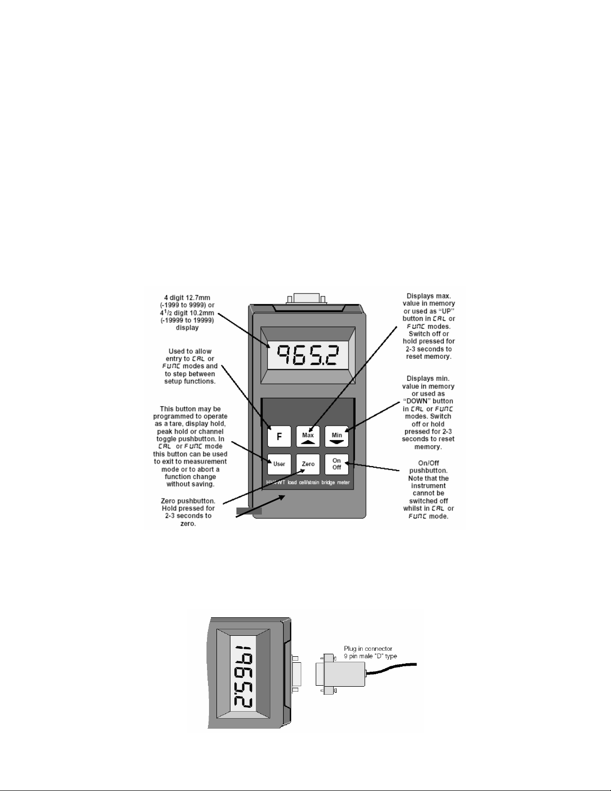
2.0 ELECTRICAL CONNECTIONS
Power for the DFI 200 is provided by a 9VDC (216) battery. The battery cover is located at the underside of the
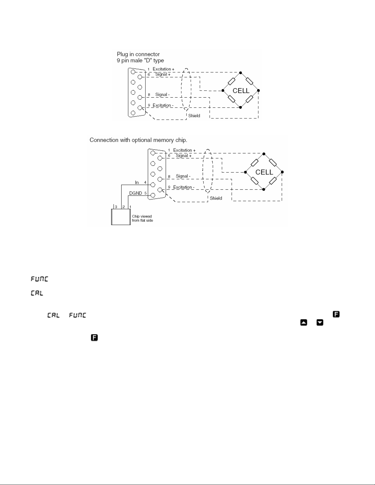
case. External connections to the DFI 200 are made via a 9 pin “D” male connector. Electrical connections are as
shown below. See "External memory" chapter for details of the optional external memory chip.
CF 112 3 2.2-0
Page 4
3.0 EXPLANATION OF FUNCTIONS
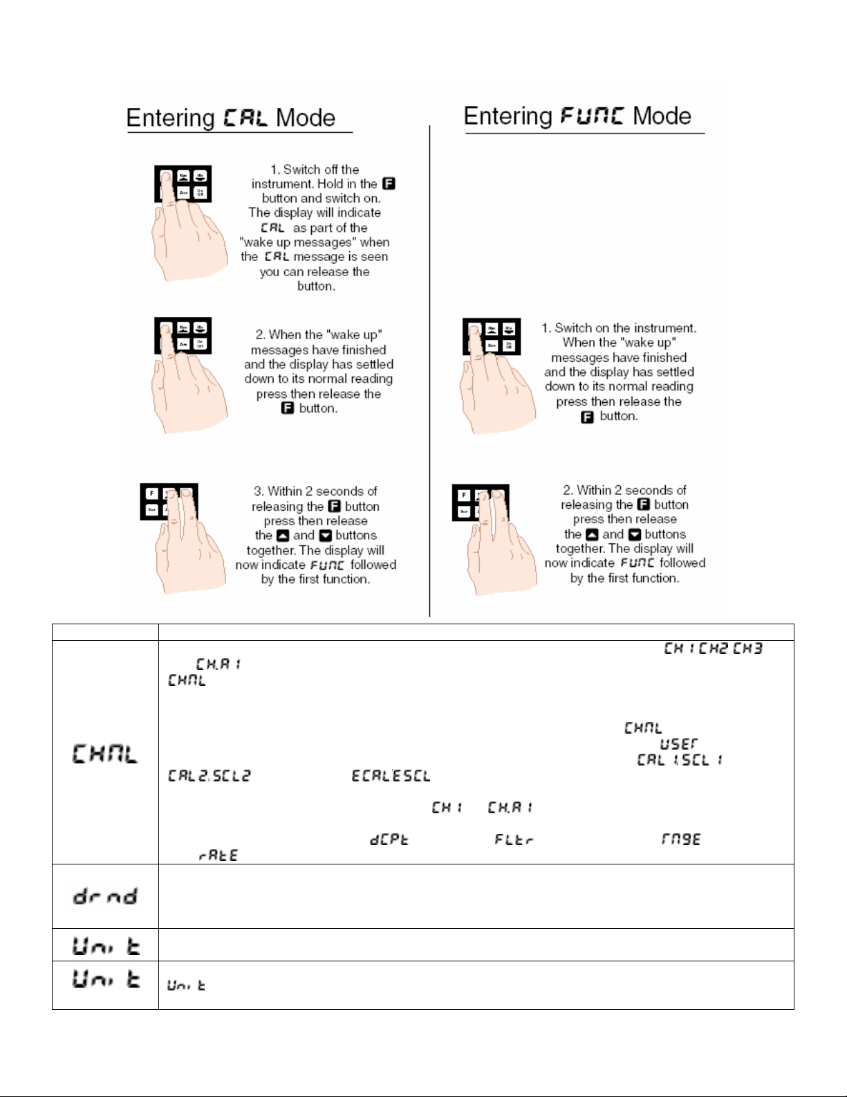
The DFI 200 setup and calibration functions are configured through a push button sequence. Two levels of access
are provided for setting up and calibrating: -
mode (simple push button sequence) allows access to calibration channel selection, display rounding,
decimal point and digital filter settings only.
mode (power up sequence plus push button sequence) allows access to all functions including calibration
parameters.
Once
push button, until the required function is reached. Changes to functions are made by pressing the
button (in some cases both simultaneously) when the required function is reached. Any changes to a function will
not be saved until the
or mode has been entered you can step through the functions, by pressing and releasing the
or push
button is pressed to accept the change.
CF 112 4 2.2-0
Page 5
Function Description
Cell calibration selection – selects one of the three possible calibration channels (
also if the optional external memory chip is used – see “External memory” chapter). The
function allows the instrument to be calibrated to up to 3 different load cells and hold the
calibration values in internal memory. Alternatively 3 different calibration scaling values may be
entered for a single cell, allowing the same cell to display in different units e.g. Kilonewtons,
Kilograms & Tonnes. The user may select the load cell to be used vial this
“User” pushbutton if the pushbutton has been programmed for this purpose (see
scale any of these independent calibration memories you may use either the
/ methods or the / method. Simply select the required cell number prior to
scaling then scale using whichever calibration method best suits the application.
The channel selected will always default to
In addition to independent calibration scalings for each channel selected each channel can be
assigned different decimal point (
rate (
Display rounding 0 displays and sets the display rounding value. This value may be set to 1-5000
displayed units. Display rounding is useful for reducing the instrument resolution without loss of
accuracy in applications where it is undesirable to display to a fine tolerance. (example: if set to 0.5
the instrument will display in multiples of 0.5 ie. 0, 0.5, 1.5, 2.0 etc).
Unit address – this function is used to display or set a unit address to one or more optional external
memory devices. For identification purposes each device should be allocated an address
if more than one external memory is used. When a sensor with a memory chip is plugged in the
Cont.
function can be used to view the address of the memory device. The address can be set from
1 to 250. If address 255 is seen this indicates that the device has not had yet had an address set. If a
, ,
function or via the
function). To
/ &
(or if external memory is used) at switch on.
), digital filter ( ), mV/V input range ( ) and sample
) settings.
CF 112 5 2.2-0
Page 6
Function Description
memory device has had an address set then the address can be viewed or altered at this function.
The procedure for setting or altering an address is as follows.
1. The
function must be set to either i.e. a memory device must be connected
2. With the external memory device connected enter function mode and step through to the
function.
3. Use the
or arrow to select the required address for that chip then press to accept
the change.
The address selected will now be stored in that memory device.
The same address can be allocated to more than one memory device and the address of a device
can be changed at any time by following steps 1, 2 & 3 above.
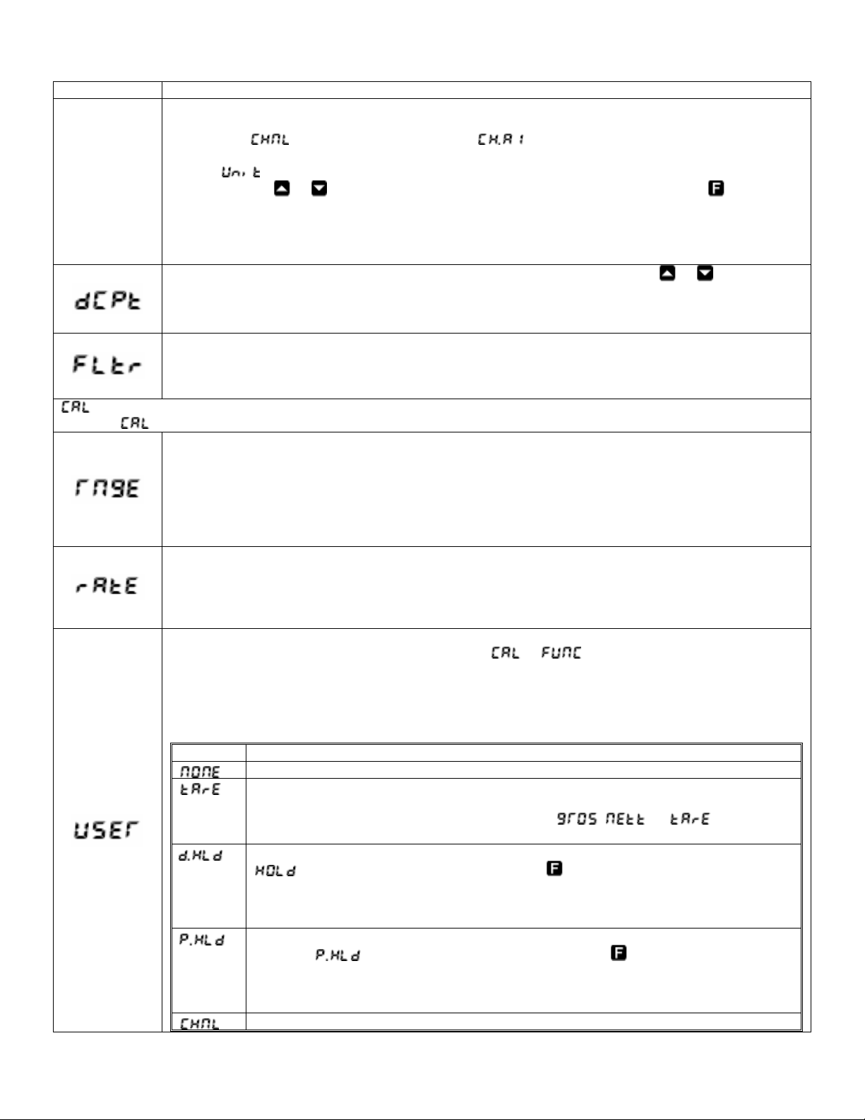
Decimal point selection – displays and sets the decimal point. By pressing the
or pushbuttons
the decimal point position may be set. The display will indicate as follows: 0 (no decimal point), 0.1 (1
decimal point place), 0.02 (2 decimal point places) or 0.003 (3 decimal point places). 3 decimal
places is the maximum for both 4 & 4½ digit displays.
Digital filter – displays and sets the digital filter value. Digital filtering is used for reducing
susceptibility to short term interference. The digital filter range is selectable from 0 to 8, where 0 =
none and 8 = most filtering. A typical value for the digital filter would be 3. The digital filter uses a
weighted averaging method of filtering which will increase the display update time at higher settings.
mode functions
Entry via mode (see first page of this chapter) must be made in order to view and adjust the functions that follow.
Full scale mV/V output of transducer – displays and sets the full scale mV/V range to suit the load
cell transducer usable range and is selected in steps as follows:
0.5, 1.0, 2.5, 5.0, 10, 20, 40, and 80
If there is no exact match to your transducer choose the next highest setting e.g. if your load cell has
2mV/V output then choose 2.5 as the range setting. Choosing a setting higher than required will
result in a loss of resolution. Choosing a setting lower than required may result in the overload
display “ - - - -“
Sample rate – displays and sets the ADC sample rate from 5 to 100 samples per second and may be
selected in steps as follows:
5, 10, 15, 20, 30, 40, 50, 60, 80 and 100
For best resolution choose the lowest acceptable sample rate. A resolution table can be found in the
Specifications chapter.
User pushbutton function – in normal measurement mode the User push button can be programmed
to operate in one of the modes described below. In
or modes pressing the User button
will cause the instrument to immediately return to normal measurement mode. Any changes to the
function selected when the button was pressed will not be saved.
Displays and sets the user pushbutton function. This function may be set to any one of the following
shown in the table below:
Function Description
No function
Push button tare – the pushbutton must be pressed for 2-3 seconds to perform a tare
operation. When tare is selected you can toggle between the nett, tare and gross
displays via the User pushbutton. The message
the measurement value.
Display hold – Press the User button momentarily to hold the display the message
, or will precede
will flash every few seconds. Press the button to reset back to normal
display. If the User button is held pressed for 2-3 seconds the held value in memory
will be reset and a the current value will be held. The display will automatically reset to
normal measurement after 20 seconds.
Peak hold – Press the User button momentarily to hold the peak value display the
message
will flash every few seconds. Press the button to reset back to
normal display. If the User button is held pressed for 2-3 seconds the peak value in
memory will be reset and a the current value will be become the new peak value. The
display will automatically return to normal measurement after 20 seconds.
Change calibration channel – Allows toggling between input readings for calibration
CF 112 6 2.2-0
Page 7

Function Description
channels (if memory device fitted) , & . If switched off then the
instrument automatically reverts to
This function is not used with standard DFI 200 instruments.
2 point calibration scaling – this is an alternative calibration method to the
note that only one method needs to be used (See “Use of
using & ). The & functions are used to set two independent
calibration/scaling points of the input to the display. This method uses two different live input values
to scale the instrument. The method is as follows:
1. Enter the setup functions via
function. The channel number selected will be the channel for which this calibration
scaling operation applies.
2. Step through the functions by pressing and releasing the
.
3. Press the release, the
4. The display will now indicate (1
5. Apply a known input to the instrument of nominally 0% (this value is not critical and may be
anywhere within the measuring range of the instrument). For example you could arrange that
the load or pressure is zero at this time. When the live reading has stabilized press the
button.
6. The display will indicate
7. Use the
8. Press the
the first point is complete).
9. The display will now indicate
second point at this stage then press and release the
seen. If you wish to enter the second point at this stage press the
simultaneously.
10. The display will now indicate
11. Apply an input of 100% (again this value is not critical, but there must be at least 10% of
rated capacity difference between
difference between
and inputs should be as large as possible).
12. When the reading has stabilized, press the
2) followed by the second scale value in memory.
13. Use the
14. Press the
second point is complete). The display will now move to the next function.
2 Point calibration graphs
(or ) when switched on again.
method of scaling,
and as reference values” if
mode and choose the required channel number at the
button until the display indicates
and buttons simultaneously to enter the calibration functions.
st
calibration point) followed by a “live” reading.
(scale 1) followed by the scale value in memory.
or button to obtain the required scale value.
button, the display will now indicate (indicating that calibration of
(2nd calibration point). If you do not wish to enter the
until the message is
or buttons
(2nd calibration point) followed by a “live” reading.
and inputs. For best accuracy the
and inputs. For best accuracy the difference between
button, the display will now read (scale
or button to obtain the required scale value.
button, the display will now read (indicating that calibration of the
CF 112 7 2.2-0
Page 8

Function Description
cont.
mV/V calibration – this is an alternative calibration method to the
scaling, note that only one of these methods should be used. The
& method of
method allows the know
rated mV/V value of the load cell to be entered followed by the maximum capacity of the load cell
in whatever measuring units are required. The mV/V value is entered to 3 decimal places (3
decimal places will automatically appear up when you enter
Maximum
value is 9.999 for a 4 digit display or 19.999 for a 4.5 digit display. If an the mV/V
figure is greater than the DFI 200 allows you can divide the
).
and values by
the same amount to give the correct scaling e.g. for a 4 digit display with an 18.000mV/V input
with a full scale reading 1000 you could enter the
value as 9.000 and the value as
500.
Note: Steps 1. to 6. which follow can be completed with or without a load cell being connected,
step 7 required the load cell to be connected.
The
/ procedure is as follows:
1. At the
function press, then release, and simultaneously to enter the
mode.
2. The display will show the previous mV/V value (or the mV/V value calculated by the DFI
200 if its last scaling was via
& ). Use the or pushbutton to enter the
known rated mV/V value of your load cell.
3. Press
4. The display will now show
5. Use the
to store this mV/V value in memory.
followed by the previous scale value.
or pushbutton to enter the full scale value of your load cell in the measuring
units you are using e.g. kilograms, tonnes etc.
6. Press
to accept this new value. Note: it is important that the actual full scale value for
the cell, i.e. maximum rated load, is entered and not simply the maximum load it will be
used to in your application.
CF 112 8 2.2-0
Page 9

Function Description
7. Once the
on the cell use either the
is required to give a zero load reference point to the instrument to eliminate any zero
offsets present in the lad cell.
Use of
and as reference values.
Note: do not use this facility if an optional external memory chip is connected.
If using the two point calibration method (
automatically calculated and stored at the
Cont.
& the and values may be viewed and a note taken of their value,
ensure that you do not change either the
the instrument is accidentally recalibrated incorrectly the
re-entered to scale the instrument back to the same load cell.
Note that the mV/V reference value stored at the
rated mV/V value for the load cell if
of rated load. For example if the manufacturer states that the load cell has a 2.000mV/V value for
the load cell if
reference value you would expect to see would be approximately half of the rated mV/V i.e
approximately 1.000mV/V.
Offset calibration – allows the instrument calibration to be offset by a single point value. This value
is added or subtracted across equally the range of the instrument. This scaling method is used to
correct for a constant error in the reading. The procedure is as follows:
1. Press, the release,
display will show the current display value.
2. Press the
3. Use the
input load.
4. Press
to accept the new scale value. The display will show to indicate that
the offset calibration scaling has been completed.
Zero range – the zero range function is expressed as a percentage of full range (0.0 to 100.0%).
The full range input is calculated by the figure minus the figure for 2 point calibration
or the figure if calibration is used. If the display value (as a percentage of range) is
greater than the percentage selected in the
display will be aborted and a message will be seen, the beeper will also sound
repeatedly. If the zero operation is successful then the instrument will beep once and the
message will be seen prior to the display value going to 0.
A zero range setting of 0.0 will mean that no zero operation is possible, a zero range setting of
100.0 will mean that the display can be zeroed at any time no matter what the display value at the
time.
Example: A load cell is calibrated using 2 point calibration the
figure is 70. If the
zeroed if the display is below approximately 18. This is calculated by (
(70-10) x 0.3=18.
Note that the zero operation is cumulative i.e. the zero operations are added in memory. For
example if the display is scaled to read from 0 to 1000 and the zero range is set a 20.0% then the
DFI 200 will allow multiple zero operations up until a total of 200 (200% of 1000 = 200) units have
been zeroed off. So, for example if the DFI 200 will allow a zero with a reading of 50, a second
zero with a display reading of 100 but a third zero with a display reading of 70 will not be allowed
since 50+100+70=220 which is over the limit of 200 set by the 20.0% zero range selection. The
best solution to allow zeroing beyond this is to set a new calibration zero reference point via the
function, alternatively the setting can be increased.
value has been entered connect the cell to the instrument. With zero load
function or operate the Zero button. This operation
& ) the mV/V value and scale is
and functions. After calibration using
or values whilst they are being viewed. If
and values recorded can be
function will only match the manufacturers
and were carried out at exactly 0% and 100%
and were carried out at 0% and 50% of rated load then the
and simultaneously ton enter the function. The
button. The display will show followed by the previous scale value.
or button to alter this scale value to the required reading for the current
function then any attempt to zero the
figure is 10 and the
function is set to 30.0 (30.0 percent) then the display can only be
- x 30%) i.e.
CF 112 9 2.2-0
Page 10

Function Description
Zero reference – this function allows the user to select a zero position anywhere within the input
range. The
function only and does not form part of the calibration scaling i.e. display values are not affected
by a
operation. Press the and buttons simultaneously to execute this function, a
live reading will be seen. Press the
message
range memory will now be cleared.
Set zero – used to set the load cell system to display reading of zero. The set zero point is entered
when the load cell is installed and in a no weight condition. To operate the set zero function
press, then release,
button to zero the display. The message
has been completed. If the zero point set by this function is lost due to subsequent from
pushbutton zero operations then in can be recovered via the
The
function operates in the same manner as the Zero pushbutton on the instrument.
The input at the time of the operation will now show as a zero display but the
calibration scaling slope is not affected.
Clear zero – the clear zero function allows the zero point to be set back to the position
programmed at the
this function. The message
Power off time – selects the automatic power off time in minutes. This function allows the
instrument to conserve batter power by automatically powering down if a button has not been
pressed for the number of minutes selected. Selections allow range from 0 to 300 minutes. If 0
minutes is selected then the instrument will not automatically power down and must be switched
off via the “On Off” pushbutton.
This function is not used with standard DFI 200 instruments.
function is provided to allow a zero reference for the
button to enter this as the new zero reference. The
will be seen to confirm that the cooperation has been completed. The zero
and buttons simultaneously, a live reading will be seen. Press the
will be seen to confirm that the operation
function (see below).
function. Press the and buttons simultaneously to execute
will be seen to confirm that the operation has been completed.
See “Serial communications” chapter.
3.1 Error Messages
“ ” This message indicates that the mV input is higher than the DFI 200 is expecting. This could be due to an
incorrect
“-
--” This message indicates that the DFI 200 is being asked to display a number which is too large e.g. a
number greater than 9999 on a 4 digit display. Check that the instrument has been correctly calibrated and that the
display range required is not greater than the number of digits on the display.
“
If you wish to proceed with the zero operation then you will find that either the value needs to be
changed or a
“
the settings and adjust either the
“
change must be a minimum of 10% of rated capacity of the load cell/pressure sensor to allow calibration.
“
automatically switch the instrument off after a selected time of no operation to extend the life of the battery.
“
” This message indicates that the instrument is about to automatically power down, see function.
function setting or an incorrectly wired or faulty load cell.
” This message means that the function setting has stopped the zero operation.
operation carried out.
” This message indicates that the value selected is higher than the setting. Check
or setting as required.
” This message indicates that the change in load between and was not enough. The
” This message indicates a low battery voltage. Fit a new battery. The function can be used to
CF 112 10 2.2-0
Page 11

“ ” This message indicates that a memory chip has been detected but that an error has occurred usually
due to a unit address not being assigned to the chip. Check that the memory chip has been assigned an address –
see
to view and change the
function for procedure. It may be necessary to manually change the function to to be able
function.
4.0 FUNCTION TABLE
Initial
display
Meaning of display Next display
Cell number selection
The functions below relate to serial communications – see “Serial communications” chapter.
Display rounding
selects resolution
Unit address for
external memory
Display decimal point
Digital filter range 0 to 8
Functions below are accessible only via mode
Full scale mV/V range 0.5, 1.0, 2.5, 5.0, 10, 20, 40, or 80 5.0
Sample rate (samples
per second)
“User” pushbutton
function
Calibration standard
two point
Calibration standard
two point
Calibration by entering
mV/V value
Offset calibration See “Explanation of functions” chapter n/a
Allowable % reading for
zero operation
Calibration zero See “Explanation of functions” chapter n/a
Set zero See “Explanation of functions” chapter n/a
Clear zero See “Explanation of functions” chapter n/a
Auto power off time
(minutes)
5, 10, 15, 20, 30, 40, 50, 60, 80 or 100 10
See “Explanation of functions” chapter n/a
See “Explanation of functions” chapter n/a
See “Explanation of functions” chapter n/a
Not used with standard DFI 200 instruments
, , or (and if
external memory used
Value in memory 1
1 to 255 255
Decimal pt position
(0, 0.1, 0.02 or 0.003)
0 to 8
(8 = most filtering)
0.0 to 100.0 10
0 to 300 10
Default
Setting
0
2
NONE
Record Your
Settings
Baud rate
Parity
Output mode
Unit address 0 to 31 0
300, 600, 1200, 2400, 4800, 9600, 19.2,
38.4
9600
NONE
Cont
5.0 EXTERNAL MEMORY
An external memory option is available for the DFI 200. The purpose of the external memory is to allow calibration
scaling details for a particular load cell to be stored; the external memory is then permanently connected to the load
CF 112 11 2.2-0
Page 12

cell. The external memory allows the DFI200 to be used with many load cells, each attached to individual memory
chips, without the need to recalibrate every time the load cell is connected i.e. each load cell requires only one
calibration. When the external memory is connected to the DFI 200 the calibration scaling data is used but the DFI
200 to display the required scale values for that load cell. The external memory will normally be housed inside the
9-pin “D” connector shell connected to the load cell although memory chips can also be used with switch boxes to
allow ease of switching between load cells.
External memory housed inside the
connector shell
Note: each external memory device should be allocated a unit address, see
to 250. If the
given an address. The same address can be allocated to more than one memory device and the address of a
device can be changed at any time. The setting of individual unit addresses simply allows identification of the load
cell by viewing the
If the error message
200 has recognized that an external memory is connected but cannot read from it. Usually the cause is that the
address of the chip is 255. To overcome this, follow the procedure below.
1. Switch on the DFI 200.
2. Go to the
3. Go to the UNIT function and select an address other than 255.
4. Continue pressing and releasing the F button until the
The external memory stores the unit address, calibration slope and zero offset values and these are read by the
DFI200 when it is connected to the external memory. The scaling values are used to display the stored calibration
for the load cell to which the external memory is connected. The external memory does not return
values to the DFI 200 therefore the
necessarily those of the cell connected. Do not view the & settings when external memory is
connected unless you wish to recalibrate the load cell since the calibration slope information for these settings will
be overwriting the calibration slope in the external memory chip.
See “Electrical connections” chapter for details of electrical wiring for the memory device.
Calibration and setup with external memory
The calibration and setup procedures are identical those described in the “Explanation of functions” chapter. If
connected to a load cell with an external memory device then you simply need to ensure that the channel you wish
to calibrate (
selected when the DFI 200 detects that a memory device is connected.
Taking readings with external memory
Once the load cell with external memory is connected to the DFI 200 the instrument will automatically display the
calibrated scaling figures for that load cell. Simply ensure that the required channel (
taking a reading. The
device is connected.
function indicates an address of 255 then this indicates that the memory device has not been
function.
is seen on attaching the external memory this error message means that the DFI
function and select .
message is seen.
& values in the DFI 200 will be those of the last cell calibrated, not
) is selected prior to any calibration or setup. The channel should automatically be
channel should automatically be selected when the DFI 200 detects that a memory
function. Valid addresses are 1
&
) is selected prior to
6.0 SERIAL COMMUNICATIONS
RS232 communications allowing continuous or polled downloading of the display data is possible on instruments
with software versions Ht0.4 or above.
CF 112 12 2.2-0
Page 13

Electrical connections
The diagram below shows the electrical connections for a DFI 200 with both serial and load cell connectors. This
dual lead arrangement allows for a convenient connection to the load cell and serial port. Note: an adaptor may be
required to allow connection directly to a serial port.
DIP switch settings
The RS232 communications can be enabled or disabled via a DIP switch SW7 located at the display end of the DFI
200 Circuit board. Switch 3 of this DIP switch is used to switch the communications facility on or off as detailed
below. To gain access to the DIP switch remove the four screws at the rear of the DFI 200 Case and remove the
back. The back is connected to the circuit board via a ribbon cable, there is no need to case and remove the back.
The back is connected to the circuit board via a ribbon cable; there is no need to unplug this cable. Once the back
is removed SW7 should be visible at the top edge of the circuit board.
SW7
Switch 3 off.
Communications disabled.
SW7
Switch 3 on.
Communications enabled.
With the communications enabled the following extra functions will be seen:
(set baud rate)
Select from 300, 600, 1200, 2400, 4800, 9600, 19.2 or 38.4 baud.
(set parity)
Select parity check bit to either
, or .
(set RS232/485 interface mode)
Select
, or
Allows user to select the RS232/485 interface operation as follows:-
Sends image data from the display without conversion to ASCII. This mode is intended for use only
when the DFI 200 is used to transmit data to a compatible display.
CF 112 13 2.2-0
Page 14

Sends ASCII form of display data every time display is updated
Controlled by computer or PLC as host.
Host sends command via RS232 and the instrument responds as requested in ASCII form. See
“Poll commands” section which follows.
(set unit address for polled ( ) mode (0 to 31)).
Allows an individual address to be assigned to a number of DFI 200 instruments. The instrument will respond with
it address proceeding the display reading.
The unit address ranges from 0 to 31 (DEC) but is offset by 32 (DEC) to avoid clashing with ASCII special function
characters (such as <STX> and <CR>). Therefore 32 (DEC) or 20 (HEX) or SPACE (ASCII) is address 0 whilst 42
(DEC) or 2A (HEX) or * (ASCII) is address 10.
If the host computer or PLC etc. uses address 0 when polling then the DFI 200 connected to the host will always
respond no matter what the
function setting. If the host uses any other address then only instruments with
the same address will respond to a polling command.
Poll commands – Host Controlled Transmit Mode:
This mode requires a host computer or PLC to poll the instrument to obtain display or other information or reset
various setpoint parameters. Communications software often known as a “terminal” program is required when using
Poll mode.
When polling the DFI 20 it is essential that the command characters are sent with less than a 10mS delay between
them. This means that each command line must be sent as a whole string e.g. <STX>PA<CR> is sent as one string
rather than <STX> on one line followed by P etc. If testing using “Telix” or other software this is normally achieved
by allocating a command string to a function key. Whenever the function key is operated the whole string is sent.
The format used is ASCII (8 data bits + 1 stop bit) so, for instance, if address 1 is used then the string
<STX>PA<CR> would typically be put into the terminal program as:
^BP!^M
where: ^B is the ASCII character for STX
P is the command line to transmit the primary display value
! is the ASCII character for address 1 (33 Dec of 21 Hex)
^M is the ASCII character for CR
A typical format for the host command is as follows: <STX>CA<CR> (Standard read)
Where: <STX> is Start of Text Character (2 Dec, 02 Hex, ^B ASCII)
C is the command character (see following commands)
A Is the unit address (Range: 32 to 63 Dec,
20 to 3F Hex, “SPACE” to ? ASCII, the address is offset by 32 Dec, 20
Hex)
CR is Carriage Return (13 Dec, 0D Hex, ^M ASCII)
The
commands available and instrument responses are as follows:
1. Transmit Primary Display Value: <STX>PA<CR>
e.g. ^BP!^M in the terminal program (address 1).
Instructs unit to return the primary display value. The primary value is the main display reading e.g. load or
pressure. Format of returned data is:-
<ACK>PAXYYYY<CR>
Where: <ACK> is Acknowledge (6 Dec, 06 Hex)
P echo command received ‘P’ (80 Dec, 50 Hex)
A is the responding unit’s address
X SPACE for positive and ‘-‘ for negative
CF 112 14 2.2-0
Page 15

YYYY is the display value in ASCII
<CR> is a Carriage Return (13 Dec, 0D Hex)
The number of display characters returned depends on the number of display digits present. If the decimal point is
non zero then it will be sent in the appropriate place as ‘.’ (46 Dec, 2E Hex).
2. Transmit Secondary Display Value: <STX>SA<CR>
e.g. ^BS!^M in the terminal program (address 1).
Instructs the unit to send the secondary display value. The value will equal the primary display value if the
function is set to . If the function is set to , , or the value for the selected
operation will be returned. Format of returned data is:
<ACK>SAYYYY <CR>
<ACK>SAYYYY,YYYY<CR> in the case of HiLo
Where: <ACK> is Acknowledge (6 Dec, 06 Hex)
S echo command received ‘S’ (83 Dec, 53 Hex)
A is the responding unit’s address
YYYY is the secondary display value in ASCII
<CR> is a Carriage Return (13 Dec, 0D Hex)
For
If is used then the primary display value transmitted will be the live input value, i.e. the gross value.
The secondary display value transmitted will be the tared value i.e the nett value.
For
value.
For
3. Transmit Instrument Model and Version: <STX>IA<CR>
e.g ^BI!^M in the terminal program (address 1)
Instructs unit to return the model and version number of the instrument.
Format of returned data is:-^^^^^
Where: <ACK> is Acknowledge (6 Dec, 06 Hex)
I is echo command received ‘I’ (73 Dec, 49 Hex)
A is the responding unit’s address
CC a 2 character model identifier (“Ht” for the DFI 200)
X.X is the version number (e.g.: “0.1”)
<CR> is a Carriage Return (13 Dec, 0D Hex)
4. Invalid Command
If the command received from the host is not valid then the unit may return the following:-
Where: <ACK> is Acknowledge (6 Dec, 06 Hex)
? is the character ‘?’ (63 Dec, 3F Hex)
A is the responding unit’s address
<CR> is a Carriage Return (13 Dec, 0D Hex)
If the address received from the host does not match the units address then the unit will not respond at all.
the primary and secondary display values will be identical.
and the secondary display will be the held value and the primary display the live input
the secondary display returned data will be the channel number i.e. 1, 2 or 3.
<ACK>IACCX.X<CR>
<ACK>?A<CR>
7.0 SPECIFICATIONS
Technical Specifications
Input:
Input sensitivity:
Bridge compatibility:
CF 112 15 2.2-0
Ratiometric 4 wire strain gauge
0.5 mV/V to 100mV/V selectable
80Ω to > 2000Ω
Page 16

Excitation:
Accuracy:
Sample rate:
ADC resolution:
ADC conversion:
Microprocessor:
Ambient temperature:
Humidity:
Display:
Power supply:
Communications:
Low battery warning:
Options
External memory:
5VDC
Up to 0.005% of full scale dependant upon sample rate selection
If
/ method is used then accuracy is 1% of full scale.
5 to 100 per sec selectable
Up to 22 bits, see table and uV calculations below.
Sigma Delta
MC68HC11 CMOS
0 to 50°C
5 to 95% non condensing
Model DFI 200 4½ digit 11.7mm (-19999 to 19999)
Battery 9VDC type 216 (alkaline recommended)
Inbuilt RS232 communications. Maximum serial output approx. 65 samples/sec
with
function set at 100 and set to .
message + beeper
Memory chip, 9 pin D connector & shell
Physical Characteristics
Dimensions: 80mm (w) x 145mm (l) x 32 to 39mm (d)
Connections: 9 pin “D” connector, female at instrument end.
Weight: 250 gms. including battery.
Effective Resolution (Bits) DFI 200 Over Full Scale
mV/V Input
Samples/Second 0.5 mV/V 1mV/V 2.5mV/V 5mV/V 10mV/V 25mV/V 50mV/V or 100mV/V
5 15.5 16.5 17.5 18.5 19.5 20.5 20.5
10 15.5 16.5 17.5 18.5 19.0 19.0 19.0
15 15.5 16.5 17.5 18.5 18.5 19.0 19.0
20 15.5 16.5 17.5 18.0 18.5 18.5 18.5
30 15.5 16.5 17.5 18.0 18.5 18.5 18.5
50 15.0 16.0 16.5 17.0 17.5 17.5 17.5
100 14.0 14.0 14.5 14.5 15.0 15.0 14.5
Note: Figures in the table above apply when the digital filter setting is 0. Add 0.5 bits effective resolution for each
step on the digital filter setting e.g. if the digital filter is set at 4 add 2 bits of effective resolution to each of the
figures in the table above.
Resolution in uV can be calculated using the resolution in bits figures above. These uV resolution values are
calculated by the following method:
Resolution (uV) = full signal input voltage range / number of divisions of resolution.
e.g. for 2.5mV/V range full signal input voltage is 2.5mV x 5V excitation = 12.5mV.
For 14.5 bits (100 samples/sec, zero filter) the number of divisions is 2
For 21.5 bits (5 to 30 samples/sec, filter setting of 8) the number of divisions is 2965820 (2
14.5
which equals 23170 divisions.
21.5
).
Resolution (uV) at 14.5 bits = (2.5 mV x 5) / 23170 = 0.54uV
Resolution (uV) at 21.5 bits = (2.5 mV x 5) / 2965820 = 0.0042uV
8.0 WARRANTY
Limited Warranty on Products
Any Cooper Instruments product which, under normal operating conditions, proves defective in material or in
workmanship within one year of the date of shipment by Cooper will be repaired or replaced free of charge provided
that a return material authorization is obtained from Cooper and the defective product is sent, transportation
charges prepaid, with notice of the defect, and it is established that the product has been properly installed,
maintained, and operated within the limits of rated and normal usage. Replacement or repaired product will be
shipped F.O.B. from our plant. The terms of this warranty do not extend to any product or part thereof which, under
normal usage, has an inherently shorter useful life than one year. The replacement warranty detailed here is the
CF 112 16 2.2-0
Page 17

buyer’s exclusive remedy, and will satisfy all obligations of Cooper whether based on contract, negligence, or
otherwise. Cooper is not responsible for any incidental or consequential loss or damage which might result from a
failure of any and all other warranties, express or implied, including implied warranty of merchantability or fitness for
particular purpose. Any unauthorized disassembly or attempt to repair voids this warranty.
Obtaining Service under Warranty
Advance authorization is required prior to the return to Cooper Instruments. Before returning the item, contact the
Repair Department c/o Cooper Instruments at (540) 349-4746 for a Return Material Authorization number.
Shipment to Cooper shall be at buyer’s expense and repaired or replacement items will be shipped F.O.B. from our
plant in Warrenton, Virginia. Non-verified problems or defects may be subject to a $100 evaluation charge. Please
return the original calibration data with the unit.
Repair Warranty
All repairs of Cooper products are warranted for a period of 90 days from date of shipment. This warranty applies
only to those items that were found defective and repaired; it does not apply to products in which no defect was
found and returned as is or merely recalibrated. It may be possible for out-of-warranty products to be returned to
the exact original specifications or dimensions.
* Technical description of the defect: In order to properly repair a product, it is absolutely necessary for Cooper to
receive information specifying the reason the product is being returned. Specific test data, written observations on
the failure and the specific corrective action you require are needed.
CF 112 17 2.2-0
 Loading...