

Page 1

DFI 1550/1650
COMMUNICATIONS GUIDE
Page 2

Table of Contents
Chapter 1 Introduction................................................................................................................................... 1
1.1 About This Manual...............................................................................................................................1
1.1.1 Scope............................................................................................................................................1
1.1.2 Conventions ..................................................................................................................................1
1.2 Related Documents.............................................................................................................................1
1.3 What is the DFI Series? ......................................................................................................................1
1.3.1 Features........................................................................................................................................1
1.3.2 Chassis Models.............................................................................................................................1
1.3.3 Channel Types.............................................................................................................................. 2
1.4 What is Calibration? ............................................................................................................................2
1.4.1 Overview ....................................................................................................................................... 2
1.4.2 Benefits .........................................................................................................................................2
1.4.3 Information Stored ........................................................................................................................ 2
Chapter 2 Getting Started Quickly ................................................................................................................3
2.1 Introduction..........................................................................................................................................3
2.2 Locate Required Parts and Information...............................................................................................3
2.3 Connect the Instrument to the Computer's RS-232 Serial Port ..........................................................3
2.4 Turn on the Instrument ........................................................................................................................ 3
2.5 Configure a Terminal Emulator Program ............................................................................................4
2.6 Establish Communications .................................................................................................................. 4
2.6.1 Example 1 .....................................................................................................................................4
2.6.2 Example 2 .....................................................................................................................................4
Chapter 3 Command Format ........................................................................................................................4
3.1 Introduction..........................................................................................................................................4
3.2 Baud Rate, Start Bits, Stop Bits and Parity ......................................................................................... 4
3.3 Differences between Instruments........................................................................................................4
3.4 Two Types of Commands ...................................................................................................................5
3.4.1 System Commands.......................................................................................................................5
3.4.2 Channel Commands ..................................................................................................................... 5
3.5 Addressing........................................................................................................................................... 5
3.6 Command Format................................................................................................................................5
3.6.1 Format........................................................................................................................................... 5
3.6.2 Command Codes..........................................................................................................................6
3.6.3 Attention Character.......................................................................................................................6
3.7 Response Format ................................................................................................................................6
Chapter 4 RS-232 Installation Notes ............................................................................................................6
4.1 Introduction..........................................................................................................................................6
4.2 System Connector Pinout.................................................................................................................... 6
4.3 Operation Notes ..................................................................................................................................7
4.4 Typical Wiring Diagrams......................................................................................................................7
Chapter 5 RS422/RS-485 Installation Notes ................................................................................................ 8
5.1 Introduction..........................................................................................................................................8
5.2 Installation Overview ........................................................................................................................... 8
5.3 System Connector Pinout.................................................................................................................... 8
5.4 RS-422 Wiring ..................................................................................................................................... 9
5.5 RS-485 Wiring ..................................................................................................................................... 9
5.6 Addressing........................................................................................................................................... 9
5.6.1 Determine Address ..................................................................................................................... 10
5.6.2 Change Address ......................................................................................................................... 10
Chapter 6 Application Programs ................................................................................................................. 10
6.1 Introduction........................................................................................................................................10
6.2 HyperTerminal ...................................................................................................................................10
6.2.1 Start the Program........................................................................................................................10
6.2.2 Create a New Connection........................................................................................................... 10
6.2.3 Establish Communications .........................................................................................................12
6.3 WinWedge .........................................................................................................................................12
CF 126 ii Nov 2001
Page 3

6.4 QBasic I QuickBasic ..........................................................................................................................12
6.5 Visual BASIC 5 or 6........................................................................................................................... 12
6.5.1 MSCOMM Active X Control ........................................................................................................12
6.5.2 Third party Active X controls and DLLs ......................................................................................13
6.6 C and C++ ......................................................................................................................................... 13
6.6.1 Win32 API ...................................................................................................................................13
6.6.2 Third-party Libraries.................................................................................................................... 13
6.7 LabVIEW ...........................................................................................................................................13
6.8 Trademarks .......................................................................................................................................13
Chapter 7 System Commands....................................................................................................................14
7.1 Introduction........................................................................................................................................14
7.2 Listings.......................................................................................................................................... 14
7.3 Descriptions.......................................................................................................................................14
Chapter 8 Strain-Gage Input Channel Commands.....................................................................................23
8.1 Introduction........................................................................................................................................23
8.2 Descriptions.......................................................................................................................................23
Chapter 9 AC-AC LVDT Input Channel Commands...................................................................................30
9.1 Introduction........................................................................................................................................30
9.2 Descriptions.......................................................................................................................................30
Chapter 10 High-Level Input Channel Commands ..................................................................................... 36
10.1 Introduction......................................................................................................................................36
10.2 Descriptions.....................................................................................................................................36
Chapter 11 Relay Output Channel Commands ..........................................................................................43
11.1 Introduction......................................................................................................................................43
11.2 Descriptions.....................................................................................................................................44
Chapter 12 DAC Output Channel Commands............................................................................................46
12.1 Introduction......................................................................................................................................46
12.2 Descriptions.....................................................................................................................................46
Chapter 13 Split-Display Virtual Channel Commands ................................................................................ 48
13.1 Introduction......................................................................................................................................48
13.2 Descriptions.....................................................................................................................................48
Chapter 14 Mathematics Virtual Channel Commands................................................................................ 50
14.1 Introduction......................................................................................................................................50
14.2 Descriptions.....................................................................................................................................50
Warranty and Repair Policy ........................................................................................................................52
CF 126 iii Nov 2001
Page 4

Chapter 1 Introduction
1.1 About This Manual
1.1.1 Scope
This manual contains information about the wiring and protocol used for serial communications SC series
instruments. This series includes the models DFI 1550, DFI 1650, DFI 1650PT, and DFI 1650-3004.
Nearly all of the DFI’s features available via its front panel switches, indicators, display and rear panel
connectors are also available through its serial communications interface. This guide is primarily intended
for those DFI users already familiar with RS-232 and RS-422/RS- 485 serial communications interfaces
and who wish to use the DFI remotely using them. If you are not familiar with serial communications terms
such as "baud rate" and "ASCII character", you may wish to review the subject before using this guide.
The information and programs contained in this manual are believed to be correct, however no warranty
is expressed or implied including fitness for a particular purpose. The capabilities of the instrument are
continuously being improved upon, and the information in this manual is subject to change without notice.
1.1.2 Conventions
This manual uses the following conventions to present information:
[TEXT IN BRACKETS] The label of a front panel button.
DISPLAY
->
DATA
↵
1.2 Related Documents
Instruction Manual
The Serial Communications Guide explains the setup, features and operation of 3rd generation DFI
instruments.
1.3 What is the DFI Series?
The DFI Series of Signal Conditioners/Indicators are versatile, multi-channel devices designed to operate
with many different types of sensors. Several different 9 chassis types, Input channels, and Output
channels are available to allow the configuration of a DFI instrument to meet a variety of measurement
and control needs. The operation of a DFI instrument is based on digital technology to provide improved
accuracy, superior ease of setup, and a wealth of features.
1.3.1 Features
The main features of the DFI Series are:
• Four alarm limits (optional sixteen), with versatile setup (not available on Model DFI 1550).
• Automatic setup, calibration, and scaling of strain-gage sensors through the use of Signature
Calibration TM
• Field selectable, digital, low-pass filtering ("damping") on each Input channel
• Up to ±50,000 part resolution
• Field selectable five-, six- or seven-digit (9,999,999 maximum) display
• RS-232 communications standard (RS-485 optional)
• Local or remote setup using the RS-232 or RS-422/RS-485 port
• Push-button on/off tare feature
• No knobs or adjustments
1.3.2 Chassis Models
Several models (i.e. chassis types) are available:
Text that appears on the display, such as error messages or menu items.
Indicates that what follows is an item from a sub-menu, such as SYSTEM
MENU -> DIAGNOSTICS.
Commands sent to or replies from the instrument
The carriage-return character, ASCII code decimal 13
CF 126 1 Nov 2001
Page 5

• DFI 1550: 1 to 4 physical channels, 3/8 DIN case, no limits or peak detector
• DFI 1650: 1 to 4 physical channels, 3/8 DIN case
• DFI 1650PT: 1 to 4 physical channels, portable case
• DFI 1650-3004: 1 to 14 physical channels, 19" rack mount case, 1 to 3 quad-Iine displays
1.3.3 Channel Types
Channels can be one of three types: Input, Output, or Virtual
Input Channels Input channels are hardware circuit boards with a unique channel number. Currently,
they are available for the following types of sensors:
• Strain-gage sensors, such as unamplified pressure transducers and load cells
• Sensors with voltage outputs
• Sensors with current outputs
• AC-AC LVDTs (Linear Variable Displacement Transducers)
• DC-DC LVDTs
Output Channels Output channels are hardware circuit boards with a unique channel number. They
include:
• Relay Output channels, which can add additional limits to the standard four (N/A on DFI 1550).
• DAC Output channels, which provide additional voltage or current outputs.
Virtual Channels Virtual channels are software-based devices that occupy a channel number, but not a
physical slot, in an instrument.
• Split Display Virtual channels allow the displaying of any two channel's track, peak or valley
values at the same time.
• Mathematics Virtual channels run small programs written in an interpretive language called
SensoCode. This provides great flexibility which allows the DFI Series to do many jobs which
otherwise requires a personal computer or PLC.
1.4 What is Calibration?
1.4.1 Overview
A small integrated circuit is located either inside the transducer, in an in-Iine package between the
instrument and the transducer, or in the connector of a cable. All data necessary to set up the transducer
with the instrument are stored (even linearity data), and setup is automatic when a new transducer is
connected to the instrument.
The Strain Gage Input channel of the DFI Series is designed to operate with Signature Calibration. It will
automatically set itself up with transducers that contain the memory device, but can also be set up using a
front-panel interactive procedure. The Signature Calibration module can also be programmed from the
instrument's front panel.
Calibration is only available with un-amplified strain-gage transducers.
1.4.2 Benefits
The benefits are:
• The transducer's Calibration Record is always located where it is needed most - with the
transducer.
• The instrument is always set up correctly with the transducer.
• Interchanging of transducers and instruments is a quick process.
• A User Calibration Data area that can be altered by customers to fit their requirements.
• A Factory Calibration Sheet Data area, unalterable by the customer, can be copied back into the
User Calibration Data.
1.4.3 Information Stored
The following information is stored inside transducers equipped with Calibration:
CF 126 2 Nov 2001
Page 6

• Full-scale mV/V: The full-scale millivolt-per-volt (mV/V) rating of the transducer when its full load
is applied; also called "calibration factor".
• Shunt-Cal mV/V: The millivolt-per-volt output of the transducer when the shunt calibration resistor
is placed across its -SIGNAL and -EXCITATION leads.
• Shunt Resistance: The resistance value, in Ohms, that was used to obtain the shunt-cal mV/V
value above.
• Full-Scale Value: The full-scale value of the transducer, in engineering units.
• Engineering Units: The engineering units that the transducer is calibrated in (i.e. pounds, grams,
Pascals, inches of water, etc.)
• Serial Number: The serial number of the transducer.
• Excitation Voltage: The magnitude and type of signal used to excite the transducer.
• Linearization Points (optional): These can be used by an instrument using Shunt Calibration or
Millivolt-per-Volt Calibration to correct any non-linearity in the transducer and thus improve the
accuracy of the system. An additional "multiple-point calibration" can be purchased with the
transducer that allows linearity correction information to be placed into its Calibration module.
Chapter 2 Getting Started Quickly
2.1 Introduction
This chapter explains how to quickly establish communications with a DFI Series instrument equipped
with the standard RS-232 interface. It assumes that you are very familiar with serial communications and
have access to a terminal emulator program.
Most computers are equipped with either a standard 25-pin male or an IBM 9-pin male RS-232 serial
connector.
Remember that all personal computer serial ports have male connectors! Parallel printer ports have
female connectors.
RS-422 or RS-485 serial ports are NOT STANDARD EQUIPMENT on PC computers!
2.2 Locate Required Parts and Information
The following items are required quickly establish communications with a DFI Series instrument equipped
with the standard RS-232 interface.
• DFI Series instrument
• A computer that is running a terminal emulator program that you are familiar with.
• 25-pin D-sub pass-through male/female cable, such Radio Shack pin 26-240.
• If your computer's serial port has a 9-pin D-sub male connector, an adapter to convert the
computer's male 9-pin RS-232 port to a standard male 25-pin port. Example: Radio Shack pin 26-
209.
• The Customer Information Sheet that shipped with your instrument. Examine it to confirm that the
instrument is equipped with the standard RS-232 interface.
• Power cord for the instrument.
2.3 Connect the Instrument to the Computer's RS-232 Serial Port
Connect the 25-pin serial cable (female connector) or 25-pin serial cable plus 9-pin adapter (female
connector) to the computer's RS-232 serial port (male connector). Determine if this port is called out as
COM 1 or COM2.
Connect the 25-pin cable (male connector) to the instrument's System connector (female connector).
In nearly all situations, a gender changer device is not required! Do not connect the serial
communications cable to your computer's female printer port.
2.4 Turn on the Instrument
Connect the power cord between the instrument power source and the instrument, and turn the OnlOff
switch on the back of the instrument to the On position.
CF 126 3 Nov 2001
Page 7

The instrument enters its INITIALIZE mode that lasts a few seconds per channel. When the instrument
enters its normal operating mode (RUN mode), you will see the following format on the front panel
display:
1 c ШШШШШ. PSIG ◊
2.5 Configure a Terminal Emulator Program
Start your favorite terminal emulator program. Configure it to communicate with the serial port you have
connected the instrument to (usually COM1 or COM2), at 9600 baud, no parity bits, 8 data bits and 1 stop
bits ("9600,8,N, 1"). Disable any hardware or software handshaking or flow control such as (RTS/CTS
handshaking, DSR/DTR handshaking or Xon/Xoff flow control.
2.6 Establish Communications
The following examples assume that the two-character address of the instrument is the factory default of
"00" (ASCII code decimal 30, ASCII code decimal 30).
2.6.1 Example 1
All instruments will respond to the "RR: Read Revision" command. Type the following command into your
terminal emulator software, followed by the Enter key:
#00RR↵
You should see a reply from the instrument similar to:
084-1500-01 2.07
2.6.2 Example 2
The "FI: Display Characters" command can be used to send a message to the instruments display. For
example, type the following command into your terminal emulator program:
#00FIHELLO, WORLD↵
The instrument will acknowledge with "OK" and the characters "HELLO, WORLD!" III should be displayed
on the instrument's front panel.
Chapter 3 Command Format
3.1 Introduction
All DFI instruments have a standard DB-25 type female connector that is used for both serial
communications and other control functions. One of two communications hardware interfaces is available:
RS-232 or RS-485. Instruments equipped with the RS-485 two-wire interface can also be used in an RS422 four-wire type setup; thus this interface is sometimes called RS-422/RS-485. Regardless of the type
of hardware interface used, the SC uses the same software command set, the general format of which is
described in this chapter.
3.2 Baud Rate, Start Bits, Stop Bits and Parity
DFI Instruments always use 8 data bits, one start bit and one stop bit and no parity bits (often described
as "N81 ") for serial communications. Baud rates of 300, 1200, 2400, 4800, 9600, 19200 or 38400 baud
are available. As shipped from the factory, DFI Instruments are set to communicate at 9600 baud. The
baud rate can be viewed from the front panel but can only be changed over the serial communications
link. For details on changing the baud rate, see "W1 Write Baud Rate".
3.3 Differences between Instruments
The commands described in this guide may not be available on all versions of DFI series instruments.
For example, since the model DFI 1550 does not have "limits" or "peak/valley" functions, commands
CF 126 4 Nov 2001
Page 8

relating to this functionality will not work with it. If a command is not available on such an instrument, it will
be mentioned in the description for that command.
Likewise, if your instrument is not equipped with an optional Relay/DAC channel, commands relating to
relays and DAC outputs will not work on your instrument.
3.4 Two Types of Commands
3.4.1 System Commands
System commands are commands that apply to the entire instrument. For example, since the instrument
has one serial communications port all commands that apply to serial communications are system
commands.
3.4.2 Channel Commands
Channel commands are those that affect the operation of only one particular channel. For example, if the
full-scale range of a Strain Gage Input channel is altered, it applies only to a single channel of the
instrument and not the entire instrument.
3.5 Addressing
Every instrument on the communications loop must have a unique two-character address. As shipped
from the factory, every DFI has an address of "00" (ASCII codes decimal 30, decimal 30). This address
can only be viewed, not changed, from the front panel. An instrument's address can only be changed over
the serial communications link. For details on addressing, see "Addressing".
3.6 Command Format
3.6.1 Format
An example command is shown below:
#0002WK0169.89↵
where:
# is called the attention character, which alerts all instruments that a command is being
transmitted to them. This character is ASCII code decimal 35.
00 is the two-character address of the SC to be communicated with. Each character must
be a number or an uppercase letter.
02 is the two-numeric-ASCll-character channel number to which this command will apply.
When using system commands that affect the entire instrument, the channel number can
be "00" (zero, zero) or it can be omitted altogether.
WO is the two-character command to be executed. A list of the valid system commands is
given at the beginning of "System Commands". Lists of the valid channel commands are
given at the beginning of the remaining chapters.
01 is an optional two numeric character parameter number needed by some commands.
69.89 is the optional argument to be written to the instrument.
↵ represents the carriage return (ASCII code decimal 13), which indicates the end of the
command.
For example, the system command string “#00W12400”, followed by a carriage return, will cause the
instrument addressed as "00" to process the "W1 " command with a data value of "2400". The W1 system
command changes the baud rate 2400 baud.
An example of a channel command string is “#0301F1”, This command, followed by a carriage return,
causes the instrument addressed as "03" to process the "F1" command on channel "01 ". The "F1"
command activates the tare function, and thus this command string activates the tare function for channel
01.
CF 126 5 Nov 2001
Page 9

3.6.2 Command Codes
The first character of each two-character command code signifies if that command is a function command
("F"), a read operating parameter command ("R"), or a write operating parameter command ("W"). Read
and write commands can be used instead of the front panel setup menus to configure the operation of the
instrument. Function commands are used as an alternative to the front panel to gather data from the
instrument or to cause it to perform an operation.
3.6.3 Attention Character
All characters received before the "#" (ASCII code decimal 35) attention character are ignored. Therefore,
one or more instruments can share a single communications link with other "foreign instruments" (within
the physical limits of the RS-232 8 or RS-422/RS-485 interface, of course) as long as the host or the
"foreign instruments" do not use the "#" character.
When the "#" attention character is sent, the instrument enters its receive mode and will attempt to parse
out the rest of the characters before the carriage return as a possible message. If another attention
character is received in the middle of a message, the previous incomplete message is ignored. If the
instrument receives a garbled character, or if the character received has an ASCII value larger than 127,
then the entire message sent is ignored.
3.7 Response Format
An instrument will give a response over the serial communications link for every valid and invalid
command given that uses its unique two-character address. There are four types of responses used:
• "OK", which is sent after an instrument has accepted the data presented with a write operating
parameter ("W") command, or when a function ("F") command has been completed.
• "ERROR", which is sent when an instrument has been asked to perform an invalid command, or
when invalid information is given with a write operating parameter ("W") command.
• "N/A", which is sent when you are requesting information from the instrument which is not
applicable to its present configuration. For example, requesting limit setup information from a DFI
1550 will cause this message to be sent.
• a floating point number as the result of a read operating parameter ("R") or function ("F")
command.
• other ASCII strings, such as serial numbers, dates, the front panel contents, etc.
To signal the end of a response the instrument will transmit a carriage-return (ASCII code decimal 13) if
the Auto-Linefeed function is off, or a linefeed/carriage- return (ASCII codes decimal 10, decimal 13)
when the Auto-Linefeed is on. The Auto-Linefeed status can be viewed from the front panel but can only
be changed over the serial communications link using the "W2 Write Automatic Line-feed Set- ting"
system command.
Chapter 4 RS-232 Installation Notes
4.1 Introduction
This chapter provides wiring examples and hardware information for RS-232 communications. "DTE"
(Data Terminal Equipment) will be used to refer to the personal computer, programmable controller,
terminal, data acquisition system, etc. to which the instrument is connected.
4.2 System Connector Pinout
The table below lists the pins on the System Connector used for RS-232 communication. Other pins on
the System Connector may be used for other purposes.
Table 4-1: System Connector Pins used for RS-232
Pin Name Function Input/Output Reference Pin
2 RS-232 IN RS-232 Data In Input 7
3 RS-232 OUT RS-232 Data Out Output 7
4 CTS RS-232 Clear to Send (connected to pin
N/A N/A
5)
5 RTS RS-232 Request to Send (connected to N/A N/A
CF 126 6 Nov 2001
Page 10
pin 4)
6 DSR RS-232 Data Set Ready Output 7
7 GND RS-232/RS-485 reference Reference 8 DCD RS-232 Data Carrier Detect (not
N/A N/A
connected)
20 DTR RS-232 Data Terminal Ready (not
N/A N/C
connected)
22 RI RS-232 Ring Indicator (not connected) N/A N/C
The RS-232 communications pins are electrically isolated from the rest of the instrument.
The RS-232 and RS-485 interfaces are exclusive; an instrument cannot have both.
4.3 Operation Notes
If the DTE wishes to send a command to the instrument, it should first wait for the DSR line (pin 6) to be
high. Then, the DTE can send the command string (which starts with the '#' character and ends in a
Carriage Return). See "Command Format" for further information.
If the address sent by the DTE matches the address of the instrument and the command string is valid,
then the instrument pulls the DSR line low to indicate that it is busy processing the command string. After
the instrument has finished processing the command string, it will pull the DSR line high (to indicate that
new commands will be accepted) and will send the response.
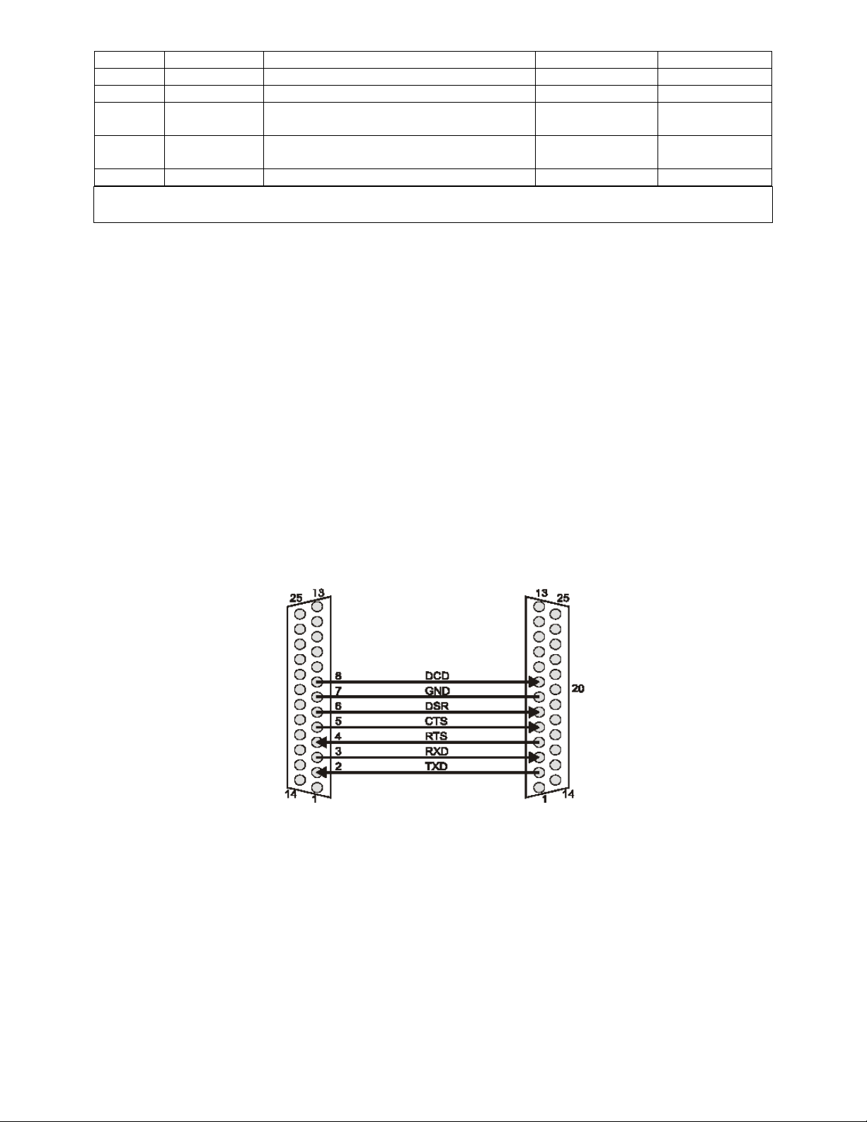
4.4 Typical Wiring Diagrams
Most computers are equipped with either a standard 25-pin male or an IBM 9-pin male RS-232 serial
connector.
Remember that all personal computer serial ports have male connectors! ~ Parallel printer ports have
female connectors. In nearly all situations, a gender changer device is not required!
Model DFI Computer or Terminal
DB 25 connector DB-25 connector
DCE DTE
Figure 4-1: Wiring to 25-pin DTE
CF 126 7 Nov 2001
Page 11
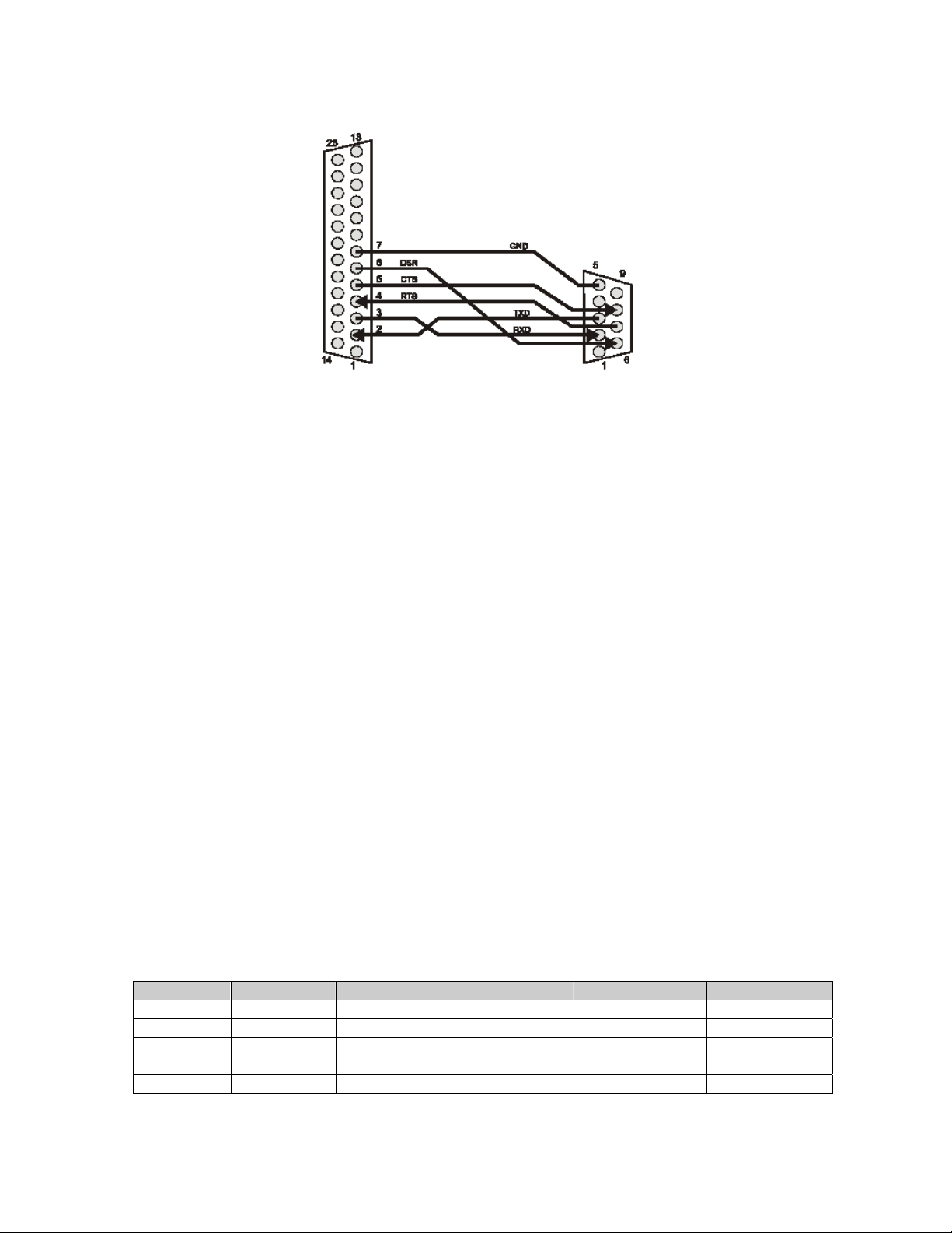
Model DFI Computer or Terminal
DB-25 connector DB-9 connector
DCE DTE
Figure 4-2: Wiring to 9-pin DTE
Chapter 5 RS422/RS-485 Installation Notes
5.1 Introduction
This chapter provides wiring examples and hardware information for RS-422/RS-485 communications.
"Bus master" will be used to refer to the personal computer, programmable controller, terminal, data
acquisition system, etc. to which the instrument is connected.
5.2 Installation Overview
Every slave instrument on the communications bus must have a unique 2-character address. Before
wiring multiple instruments into an RS-422/RS-485 communications bus, it is recommended that you read
this document thoroughly and then follow the sequence given below to avoid problems during installation.
1. Determine if the bus master has an RS-422 interface or a RS-485 interface. Wire up one, and
only one, slave instrument to the communications loop z according to the wiring diagrams in this
chapter.
2. Determine the address used by this DFI instrument (factory default is "00") by using the front
panel setup menus. This procedure is explained in (I) "Addressing". Use this address to establish
communications with this instrument.
3. Change this instrument's address to another unique value, such as "01 ", using the "W4"
command as explained in "Addressing".
4. Wire the next instrument to the communications loop and repeat steps 2-4 until the last unit is online.
5.3 System Connector Pinout
The table below lists the pins on the System Connector used for RS-422/RS-485 communication. Other
pins on the System Connector may be used for other purposes.
Table 5-1: System Connector Pins used for RS-422/RS-485
Pin Name Function Input/Output Reference Pin
7 GND RS-422/RS-485 reference Reference 12 (-) TX RS-485 Transmit - Output 7
13 (+) TX RS-485 Transmit + Output 7
24 (-) RX RS-485 Receive - Input 7
25 (+) RX RS-485 Receive + Input 7
CF 126 8 Nov 2001
Page 12
The RS-485 communications pins are electrically isolated from the rest of the instrument.
The RS-232 and RS-485 interfaces are exclusive; an instrument cannot have both.
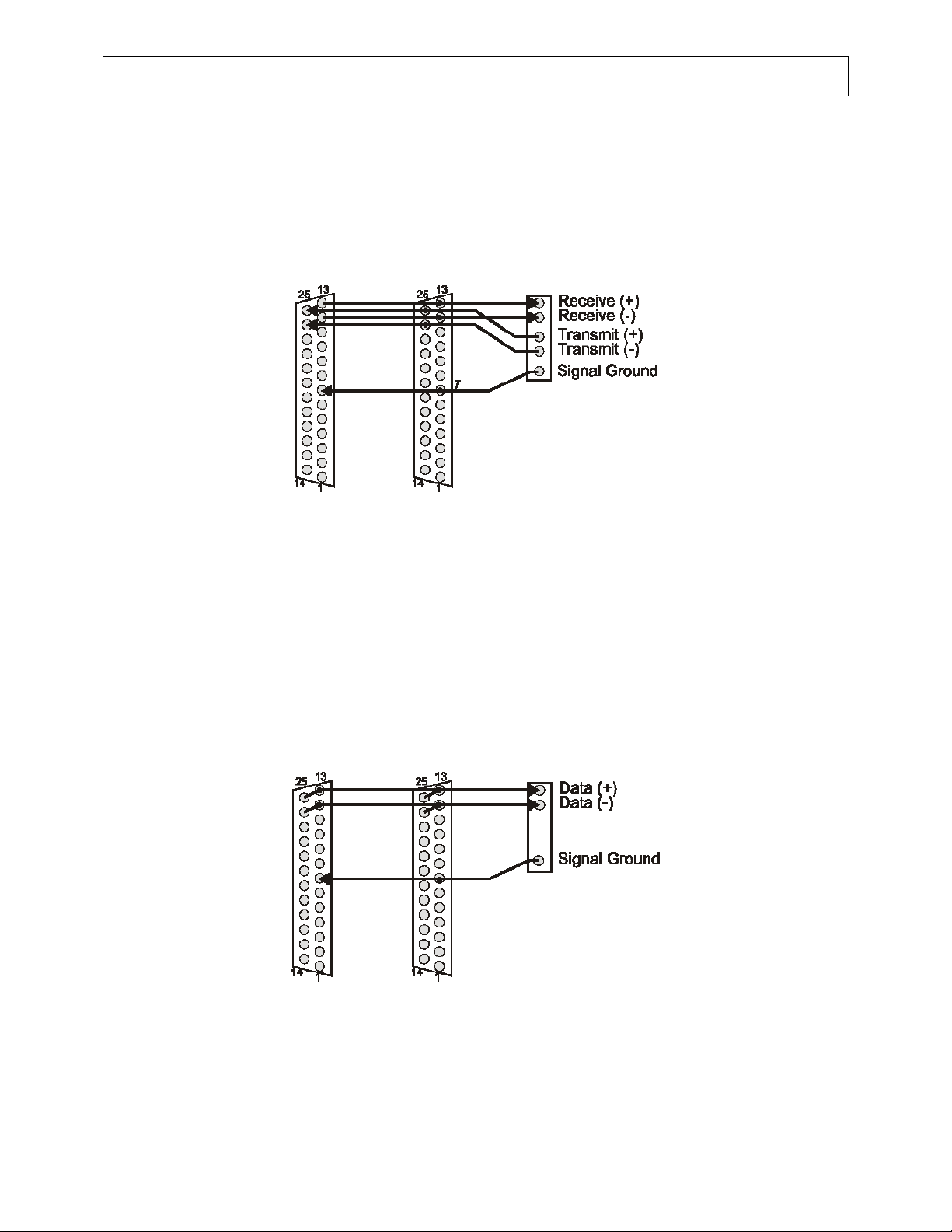
5.4 RS-422 Wiring
RS-422 uses two pairs of wires to communicate between one bus master and up to 10 slave devices. It is
a full-duplex system, i.e. the bus master can transmit and receive data from the slaves at the same time.
Model DFI Model DFI Controller
DDB-25 connector DB-25 connector RS-422
Slave Slave Bus Master
Figure 5-1:RS-422 Wiring
5.5 RS-485 Wiring
An RS-485 balanced differential communications bus uses one pair of wires to allow up to 32 devices to
send and receive data. A two-wire RS-485 system is a half-duplex system, which means that no device
can transmit and receive data at the same time, and that only one device can "drive" or "talk" on the bus
at a time. An SC Instrument is configured as a two-wire RS-485 device when "Transmit (+)" (pin 13) is
connected to "Receive (+)" (pin 25), and "Transmit (-)" (pin 12) and "Receive (-)" (pin 24) are connected
together.
Model DFI Model DFI Controller
DB-25 connector DB-25 connector RS-485
Slave Slave Bus Master
Figure 5-2: RS-485 Wiring
5.6 Addressing
Every DFI instrument on the RS-422/RS-485 communications bus must have a unique 2-character
address. Each instrument as shipped from the factory has its address set at "00" (i.e. ASCII code 30
decimal, 30 decimal).
CF 126 9 Nov 2001
Page 13

5.6.1 Determine Address
To determine what address the instrument is using from the front panel:
1) Enter the setup menus by pressing [UP] and [DOWN] together. The display will read “SETUP”
and then “CHANNEL 01 MENU” (which is the top-most item on the setup menus).
2) Press and release [DOWN] until the display reads “SERIAL COM.MENU”. Press [ENTER] to
enter the SERIAL COM. menu.
3) Press and release [DOWN] until the display reads “ADDRESS". Press [ENTER] and the display
will show this DFI’s address, for example “ADDRESS 00”. The address cannot be changed from
the front panel, only from the serial port.
4) Press [EXIT] to exit the menus and restart the instrument.
5.6.2 Change Address
To change the address of a DFI instrument:
1) Establish communication with the instrument, using its present address. For F example, if the
DFI's present address is "00", the command string “#00F0” followed by a carriage return will
cause the instrument to transmit the contents of the display. If the instrument's response appears
garbled, this may be caused by improper wiring or bus termination, having two or more
instruments on the bus with identical addresses, or having the bus master's baud rate not match
that of the instrument. DFI instruments ship from the factory set at 9600 baud.
2) Use the "W4" command to change the DFI's address. For example, if you wish to change the
address of a DFI from "00" to "01 ", send it the command string “00W401” followed by a carriage
return.
Chapter 6 Application Programs
6.1 Introduction
This chapter provides several programming examples and hints for using serial communications with
various applications and programming languages.
Cooper Instruments can also be a source of application information for your specific needs.
Many other programs and languages than the ones listed here allow communication between Cooper
instruments and your computer. Cooper Instruments is not affiliated with any of these companies and
cannot provide technical support for their products.
6.2 HyperTerminal
HyperTerminal is a terminal emulator program that has shipped with Microsoft Windows operating
systems starting with Windows 95. Characters coming in over the port are sent to your screen, and
whatever you type is transmitted out. Although HyperTerminal is generally not useful for data acquisition
or control applications, it can be used to communications verification and experimentation.
6.2.1 Start the Program
If HyperTerminal is installed on your computer, it will be located under either "Start Menu -> Programs ->
Accessories -> Communications -> HyperTerminal" or "Start Menu -> Programs -> Accessories ->
HyperTerminal". If it is not installed, consult your system administrator.
6.2.2 Create a New Connection
If you see a dialog box, which asks:
"You need to install a modem before you can make a connection. Would you like to do this now?"
respond "No".
Create a new connection setup as shown on the screenshot below. Select a descriptive name you will
remember such as "Direct to COM2"
CF 126 10 Nov 2001
Page 14
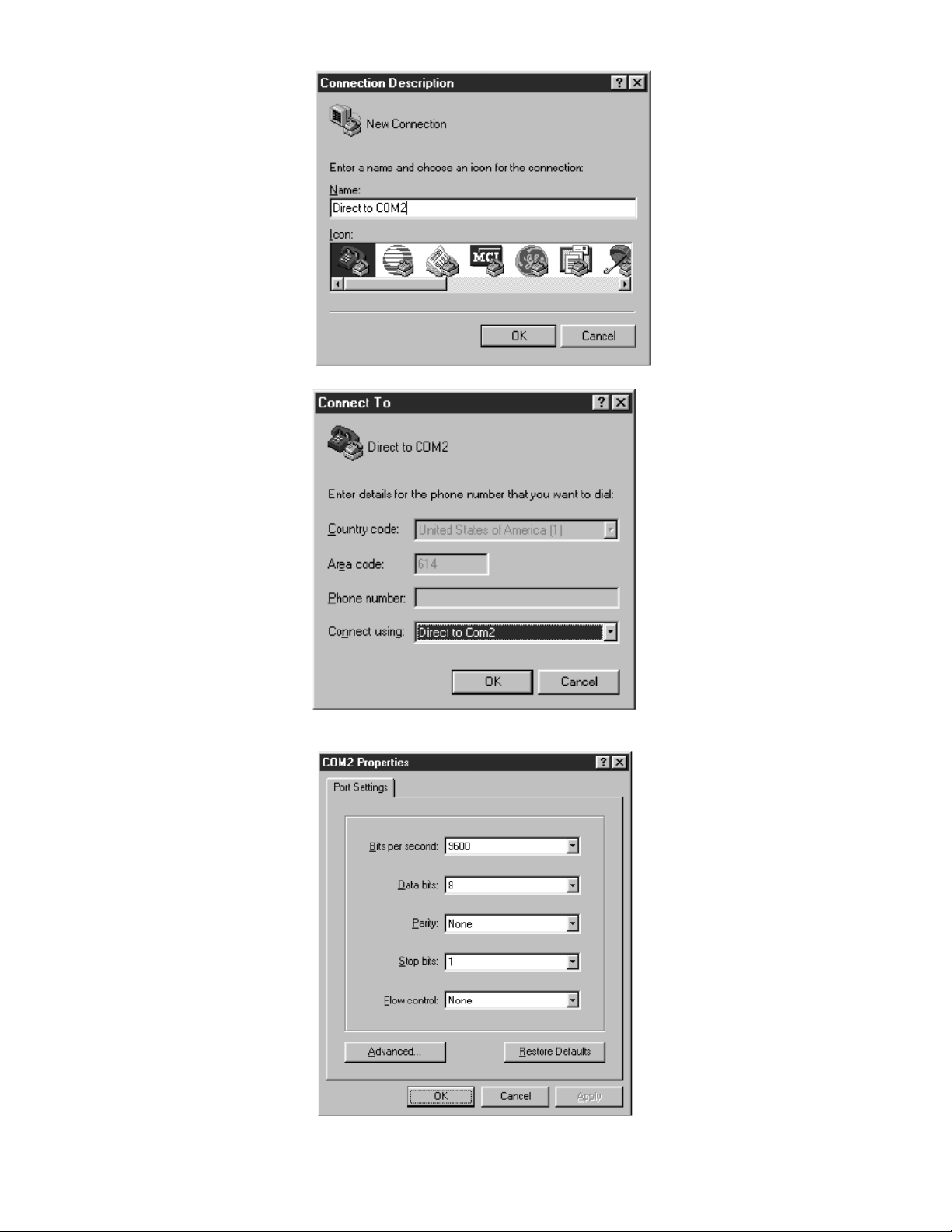
Next, select the serial port you wish to connect with.
Finally, configure the serial port parameters as shown below.
CF 126 11 Nov 2001
Page 15

If HyperTerminal reports "Unable to open Com 2" (or whatever port you are using} some other application
on your computer is currently using the port. It could be a printer, a mouse or another terminal emulation
program.
6.2.3 Establish Communications
Type “#00RR” (you will not see these characters on the screen) then press enter to transmit this
command to the instrument. If all goes well, the instrument should respond with a message in the form of
“084-1500-01 2.07”.
6.3 WinWedge
WinWedge (a.k.a. SoftwareWedge for Windows) by TALTech is a Microsoft Windows applications that
allows you to input data from a device connected to a serial port on your computer directly into any other
Windows program. The data is transferred into another Windows program (such as Microsoft Excel,
Corel Quattro Pro or Lotus 1-2-3) either as keystrokes or by using DDE (Dynamic Data Exchange).
WinWedge is easy to use for novice users and also is available in a "professional" version for more
demanding tasks. Information about WinWedge can be found at
http://www.winwedge.com
6.4 QBasic I QuickBasic
Microsoft includes a copy of QBasic (a version of QuickBasic with reduced functionality) with MS-DOS 5.0
and above, Windows 95, Windows 98, Windows NT 3.51 and Windows NT 4.0. Microsoft intended to
release QBasic with Windows 2000, but forgot to place it onto the installation CD (Microsoft support
article 0258265); they suggest copying QBasic manually from a Windows NT 4.0 computer.
Both QBasic and QuickBasic can only access ports COM1 and COM2.
Two sample programs for Microsoft QuickBasic can be located on Sensotec's web site at:
http://www.sensotec.com/scprograms/084-1031-00.zip
Note than QuickBasic's "LINE INPUT #" statement will not work when it receives a line-feed/carriagereturn combination. Therefore, you must disable the instrument's Auto Line-Feed function as explained in
"W2 Write Automatic Line-feed Setting".
6.5 Visual BASIC 5 or 6
6.5.1 MSCOMM Active X Control
Microsoft provides the MSComm ActiveX control along with Visual Basic; the file MSCOMM32.OCX is
copied and registered onto your computer when Visual Basic is installed. Some developers have been
able to use the MsComm control in VB without problems. Others, however, have encountered one or
more of the following issues:
• If you deploy your application onto a computer that does not have Visual Basic installed, you will
have to register the MSComm control manually on the other computer. Copy the file
MSCOMM32.OCX into the Windows\System directory then using the Windows "Start -> Run"
menu item type "REGSVR32 C:\Windows\System\MSCOMM32.OCX". This fix does not always
work.
• Memory leaks when using the MsComm control. See Microsoft support document Q171472.
• When another application created with Visual Basic re-installs the MsComm control and the
Visual Basic Development Environment is installed onto the same machine afterwards, you may
not be able to use the MsComm control in your VB programs. See Microsoft support document
Q177799.
For these reasons, Cooper recommends the use of a third-party Active X control or DLL for serial
communications with Visual Basic.
CF 126 12 Nov 2001
Page 16

6.5.2 Third party Active X controls and DLLs
Because of the above problems with the MsComm control, you may wish to use a third-party Active X
control for serial communications. One such product is CommX from Greenleaf software. Their web site is
located at:
http://www.greenleafsoftware.com
Several vendors offer DLL libraries for serial communications. MarshallSoft Computing offers 16-bit and
32-bit DLLs available as a shareware download. Their web site is:
http://www.marshallsoft.com
6.6 C and C++
6.6.1 Win32 API
One way of using serial communications with a C or C++ program is with the serial communications
functions of the Win32 API developed by Microsoft. These functions include CreateFile (), ReadFile () and
WriteFile (). Sample source code that demonstrates the use of these functions is available on Sensotec's
web site at:
http://www.sensotec.com/scprograms/084-1198-00.zip
The sample program was compiled with the Borland C++ compiler. Although the program is a console
mode program, the communications functions can also be used with a GUI program.
The advantage of using the Win32 API for communications is that access to it is free with your CIC++
compiler. The disadvantages are that these functions are complicated, not well documented, and do not
always work in a consistent way across Win32 operating systems.
6.6.2 Third-party Libraries
Another way of using serial communications with a CIC++ program is by purchasing a third-party library
such as CommLib from Greenleaf Software. The advantages of third-party libraries is their ease of use,
quality documentation, quantity of example code, technical support and source-code compatibility across
past, present and future operating systems.
Information about CommLib can be found at Greenleaf's web site at:
http://www.greenleafsoftware.com
6.7 LabVIEW
LabVIEW from National Instruments is a program development application, which uses a LabVIEW, uses
a graphical programming language to create programs in block diagram form. A low-cost student version
of LabVIEW is also available.
Information about LabVIEW can be found at National Instrument's web site at:
http://www.natinst.com
LabVIEW applications can use either the Serial Port VIs or VISA Vis for serial communications. A
package (Sensotec pin 084-1173-00) containing samples illustrating the use of both is available on
Sensotec's web site at
http://www.sensotec.com/scprograms/084-1173-00.zip
6.8 Trademarks
"Microsoft" and "Windows" are trademarks of the Microsoft Corporation.
"WinWedge" and "SoftwareWedge" are trademarks of TAL Technologies.
"Corel" and "Quattro" are registered trademarks of Corel Corporation.
"Lotus" is a registered trademark of Lotus Development Corporation.
CF 126 13 Nov 2001
Page 17

"CommLib" and "CommX" are trademarks of Greenleaf Software Inc.
"National Instruments" and "LabVIEW" are trademarks of National Instruments Corporation.
"MARSHALLSOFT" is a registered trademark of MarshallSoft Computing, Inc.
Chapter 7 System Commands
7.1 Introduction
System commands affect the operation of the entire instrument.
7.2 Listings
Following are the Commands listed in this section.
F0 Transmit Front Panel Display
F6 Transmit Limit Status
F8 Clear Latched Limits
FI Display Received Characters
FL Transmit Multiple Readings
FR Reset
W1 Write Baud Rate
W2 Write Automatic Line-feed Setting
W4 Write Address
RA/WA Read/Write Limit Set Point
RB/WB Read/Write Limit Return Point
RC/WC Read/Write Limit Operation
WI Write Continuous Transmit Setting
RL/WL Read/Write Multiple Readings Setup
RP/WP Read/Write Dual-Line Display Operation
RQ/WQ Read/Write Power Up Display Value
RR Read Firmware Revision
RS/WS Read/Write Channel to Display
ZM Read Scan Time
ZX Temporarily Suppress Continuous Transmissions
ZY Read Configuration
7.3 Descriptions
F0 Transmit Front Panel Display
Purpose To transmit the contents of the front panel display
Usage
Example
“#
aaF0↵”
# is the 'pound' or 'hash' character (ASCII decimal 35).
aa is the two-character instrument address.
↵ is the 'carriage return' character (ASCII decimal 13).
#00F0↵
Reply “02HI 5670.5 LBS” (typical)
Remarks This function is used to verify that communications with the instrument have been
established rather than reading data. Data is usually desired from a particular channel
number regardless of which channel the display happens to be monitoring.
The “S” and “T” display symbols are transmitted as “
“”and “” symbols are not transmitted.
HI” and “LO” respectively. The
F6 Transmit Limit Status
Purpose To transmit which of the limits have been activated
Usage
CF 126 14 Nov 2001
“#
aaF6↵”
# is the 'pound' or 'hash' character (ASCII decimal 35).
aa is the two-character instrument address.
↵ is the 'carriage return' character (ASCII decimal 13).
Page 18

Example
Reply The floating-point value in the reply is created by adding together the values for each
If “#00F6↵“ is sent when limits 02 and 04 are activated, the reply will be “10.”
activated limit as shown below.
Limit number
01 1.
02 2.
03 4.
04 8.
05 16.
06 32.
07 64.
08 128.
09 256.
10 512.
11 1024.
12 2048.
13 4096.
14 8192.
15 16384.
16 32768.
This command does not apply to instruments not equipped with limits, such as the DFI
1550.
Value
F8 Clear Latched Limits
Purpose Deactivate all latched limits
Usage
Example
Reply “OK” or “N/A”
Remarks Manually deactivates a limit that has been activated and has its “LIMIT.LATCHING” menu
“
aaF8↵”
# is the 'pound' or 'hash' character (ASCII decimal 35).
aa is the two-character instrument address.
↵ is the 'carriage return' character (ASCII decimal 13).
“00F8↵”
item set to “
button or by using the Function Input #2 pin on the rear panel System Connector.
This command does not apply to instruments not equipped with limits, such as the Model
DFI 1550.
ON”. Latched limits may also be cleared by pressing the front panel [CLEAR]
FI Display Received Characters
Purpose Display text momentarily on the display.
Usage
Example
Reply “OK”
Remarks Lower case characters are converted to upper case characters.
#
aaFIn↵”
# is the 'pound' or 'hash' character (ASCII decimal 35).
aa is the two-character instrument address.
n is the text to be displayed.
↵ is the 'carriage return' character (ASCII decimal 13).
“#
00FIHELLO WORLD↵”
The text stays on the display for about 3 seconds.
This function can be used to verify that serial communications to the instrument is
working. For RS-232 instruments, using this command can ensure that the "GND" and
"TXD" pins on the computer are properly connected to the instrument.
This command does not apply to the DFI 1650.
CF 126 15 Nov 2001
Page 19

FL Transmit Multiple Readings
Purpose Transmit a set of multiple readings as defined with the "WL" command
Usage
Example
Reply A series of ASCll-floating-point values, separated by the 'comma' character (decimal 44).
Remarks See "RL/WL Read/Write Multiple Readings Setup" for more information.
#aa
FL↵”
# is the 'pound' or 'hash' character (ASCII decimal 35).
aa is the two-character instrument address.
↵ is the 'carriage return' character (ASCII decimal 13).
Suppose that the command “#00WL01110212↵“ has been previously sent. Sending
“#00FL↵“ might result in a reply of “-001.2, 0051.3, 000.05, 100.31↵”
The format of each transmitted reading is the one that would be used to display the
readings on the front panel. Because some types of channels (such as Relay Output
channels) do not acquire or calculate data, the data read from these channels will be zero.
See "WI Write Continuous Transmit Setting" for information on how to execute this
command as quickly as possible.
FR Reset
Purpose Resets the instrument as if the power switch had been toggled
Usage
Example
Reply none
Remarks "Do not pass 'GO!' Do not collect $200." -Monopoly
“aa
FR↵”
# is the 'pound' or 'hash' character (ASCII decimal 35).
aa is the two-character instrument address,
↵ is the 'carriage return' character (ASCII decimal 13).
“00FR↵”
W1 Write Baud Rate
Purpose Writes a new baud rate for serial communications
Usage
# is the 'pound' or 'hash' character (ASCII decimal 35).
Example
Reply “OK” (at new baud rate) or “ERROR" (at present baud rate).
Remarks As shipped from the factory, DFI instruments are set to communicate at 9600 baud.
“aa
W1n↵”
aa is the two-character instrument address.
n may be 300,600,1200,2400, 4800,9600,19200 or 38400.
↵ is the 'carriage return' character (ASCII decimal 13).
Sending “#00W138400↵” will cause the instrument to communicate at 38400 baud. The
instrument will reply with “OK” at this new baud rate.
To determine what baud rate the instrument is using from the front panel:
1) Enter the setup menus by pressing [UP] and [DOWN] together. The display will read
“
SETUP” and then “CHANNEL 01 MENU” (which is the top-most item on the setup menus).
2) Press and release [DOWN] until the display reads “
[ENTER] to enter the SERIAL COM. menu.
3) Press and release [DOWN] until the display reads “
the display will show the baud rate. The baud rate cannot be changed from the front
panel, only from the serial port.
4) Press [EXIT] to exit the menus and restart the instrument.
SERIAL COM. MENU” Press
BAUD RATE". Press [ENTER] and
W2 Write Automatic Line-feed Setting
Purpose Enables or disables use of the line-feed character (ASCII decimal 10) in replies.
Usage
“aa
W2n↵”
#is the 'pound' or 'hash' character (ASCII decimal 35).
CF 126 16 Nov 2001
Page 20

aa is the two-character instrument address.
n is the argument defined below.
↵ is the 'carriage return' character (ASCII decimal 13).
Argument “0” disables the auto line-feed function. Each reply ends only with a carriage return.
“1” enables the auto line-feed function (default). Each reply ends with a line-feed/carriagereturn combination.
Example
“#00W20↵”
Reply “OK” or “ERROR”
W4 Write Address
Purpose Writes a new baud rate for serial communications
Usage
"#aa
W4nn. ↵"
# is the 'pound' or 'hash' character (ASCII decimal 35).
aa is the old two-character instrument address.
nn is the new two-character instrument address.
↵ is the 'carriage return' character (ASCII decimal 13).
Example
“#00W402↵”
Reply "OK" or "ERROR".
Remarks Each character of the new address must be alphanumeric.
Lower-case characters are converted to upper case.
As shipped from the factory, DFI instruments are set to communicate at address 00.
To determine what address the instrument is using from the front panel:
1) Enter the setup menus by pressing [UP] and [DOWN] together. The display will read
"
SETUP" and then "CHANNEL 01 MENU" (which is the top-most item on the setup menus).
2) Press and release [DOWN] until the display reads "
SERIAL COM. MENU". Press
[ENTER] to enter the SERIAL COM. menu.
3) Press and release [DOWN] until the display reads "
ADDRESS".
Press [ENTER] and the display will show the address. The address cannot be changed
from the front panel, only from the serial port.
4) Press [EXIT] to exit the menus and restart the instrument.
RA/WA Read/write Limit Set Point
Purpose Reads or writes the SET POINT of a limit.
Usage
“aa
RApp↵”to read, “aaWAappn↵“ to write.
# is the 'pound' or 'hash' character (ASCII decimal 35).
aa is the two-character instrument address.
pp is the two-numeric-character limit number.
n is the limit SET POINT value.
↵ is the 'carriage return' character (ASCII decimal 13).
Example
Sending “#00WA01325.2↵“ will change the SET POINT of Limit 1 to 325.2.
Reply When writing: "OK", "ERROR" or "N/A"
When reading: a floating-point value, or "N/A".
Remarks This command does not apply to instruments not equipped with limits, such as the DFI
1550.
RB/WB Read/write Limit Return Point
Purpose Reads or writes the RETURN POINT of a limit.
Usage
“aa
RBpp↵” to read, “#aaWBppn↵” to write.
# is the 'pound' or 'hash' character (ASCII decimal 35).
aa is the two-character instrument address.
pp is the two-numeric-character limit number.
n is the limit RETURN POINT value.
↵ is the 'carriage return' character (ASCII decimal 13).
CF 126 17 Nov 2001
Page 21

Example
Reply When writing: "OK", "ERROR" or "N/A"
Remarks This command does not apply to instruments not equipped with limits, such as the DFI
Sending “00WB04415.5↵“ will change the RETURN POINT of Limit 4 to 415.5.
When reading: an floating-point value or "N/A"
1550.
RC/WC Read/write Limit Operation
Purpose Reads or writes the operation of a limit.
Usage
Argument The argument is created by adding together the values of the desired options as shown.
Example It is desired to have Limit 1 to operate as follows:
Reply When writing: "OK", "ERROR" or "N/A".
Remarks This command does not apply to instruments not equipped with limits, such as the DFI
“#aa
RCpp↵” to read, “#aaWCppn↵” to write.
# is the 'pound' or 'hash' character (ASCII decimal 35).
aa is the two-character instrument address.
pp is the two-numeric-character limit number.
n is the argument defined below.
↵ is the 'carriage return' character (ASCII decimal 13).
Channel
01 256. OFF 0.
02 512. ON 1.
03 768.
04 1024.
05 1280. Latching
06 1536. OFF 0.
07 1792. ON 2.
08 2048.
09 2304. Source
10 2560. TRACK 0.
11 2816. PEAK 4.
12 3072. VALLEY 8.
13 3328.
14 3584.
15 3840.
16 4096. Energize
17 4352. signal<setpoint 0.
18 4608. signal>setpoint 16.
19 4864. signal inside 32.
20 5120. signal outside 48.
21 5376.
22 5632.
23 5888.
Sending "#00WC01273↵" will change Limit 1 operation accordingly.
When reading: a floating-point value described above or "N/A".
1550.
Value Enable Value
Value
Value
Value
Limit will monitor channel 01 = 256
Source of limit is track value = 0
Enable limit operation = 1
Do not latch limit after it activates = 0
Activate when signal > setpoint = 16
WI Write Continuous Transmit Setting
Purpose Enable of disable continuous transmission
Usage
“aaWIn↵”
# is the 'pound' or 'hash' character (ASCII decimal 35).
CF 126 18 Nov 2001
Page 22

aa is the two-character instrument address.
n is the argument defined below.
↵ is the 'carriage return' character (ASCII decimal 13).
Argument "0" disables continuous transmission (default). The instrument will only transmit when
requested.
"1" enables continuous transmission of the front panel display. This is equivalent to
sending the system command "F0 Transmit Front Panel Display" repeatedly. The
instrument will respond to other commands normally.
"2" performs the system command "FL Transmit Multiple Readings" repeatedly. The
instrument will respond to other commands normally.
Examples
Reply "OK" or "ERROR".
Remarks Some terminal emulator programs running under Microsoft Windows operating systems
Sending “#00WI1↵“ will cause the instrument to transmit the front panel display
contents as quickly as possible. The instrument will reply with "OK" before
commencing transmissions.
(such as HyperTerminal) may appear to "lockup" the computer after enabling
continuous transmissions with baud rates greater than 2400 baud. This is because
Windows is so busy reading and displaying the received characters that it will not
accept keyboard or mouse input.
It is a bad idea to use continuous transmission with two-wire RS-485 communications.
RL/WL Read/write Multiple Readings Setup
Purpose Read or Write how to reply to the "FL Transmit Multiple Readings" command.
Usage
Argument A list of up to 15 codes each of which indicates a channel's data value to be transmitted.
Example
“#aaRL↵” to read, “aaWLn↵” to write.
# is the 'pound' or 'hash' character (ASCII decimal 35).
aa is the two-character instrument address.
n is the argument defined below.
↵ is the 'carriage return' character (ASCII decimal 13).
Each code consists of two hexadecimal characters. The code is created by first adding
together the values of the desired options as shown in decimal and then converting the
result into hexadecimal.
Channel
01 1. TRACK 0.
02 2. PEAK 16.
03 3. VALLEY 32.
04 4.
05 5.
06 6.
07 7.
08 8.
09 9.
10 10.
11 11.
12 12.
13 13.
14 14.
15 15.
16 64.
17 65.
18 66.
19 67.
20 68.
21 69.
22 70.
23 71.
Sending “00WL031323↵” will cause the "FL Transmit Multiple Readings" command to
Value Source Value
CF 126 19 Nov 2001
Page 23

reply with the track, peak and valley values of channel 03. The instrument will reply with
"OK".
Reply When writing: "OK", "ERROR" or "N/A".
When reading: a list of hexadecimal characters as explained above.
Remarks See "FL Transmit Multiple Readings" and "WI Write Continuous Transmit Setting" for
more information.
RP/WP Read/write Dual-Line Display Operation
Purpose Read or Write the operation of the dual-Iine display
Usage
Parameters&
Arguments
Example
Reply When writing: "OK" or "ERROR"
Remarks Not available on the DFI 1650.
“#aa
RPpp↵” to read, “#aaWPppn↵” to write.
# is the 'pound' or 'hash' character (ASCII decimal 35).
aa is the two-character instrument address.
pp is one of the two-character parameters given below.
n is the argument.
↵ is the 'carriage return' character (ASCII decimal 13).
Using pp="00" reads/writes the lower line's display mode.
When writing this parameter:
n=0 blanks the lower-Iine
n=1 displays the limit indicators
n=2 displays the channel specified with parameter "80"
Using pp="01" reads/writes the channel displayed on the lower line. When writing this
parameter, n is the channel to be displayed. See ***ken for encoding information.
Using pp="80" reads/writes display operation.
When writing this parameter:
n=0 enables the display (default)
n=1 disables the display. The display will be blanked after power up until a front
panel button is pressed.
Sending “#00WP0001↵” will cause the lower line to display the limit indicators. The
instrument will reply with "OK".
When reading: a numeric value
RQ/WQ Read/write Power-Up Display Value
Purpose Read or Write which channel and data value is displayed when the instrument is
powered up.
Usage
Argument A number that selects a channel's value. This number is created by adding together the
“aa
RQ↵” to read, “#aaWQn↵” to write.
# is the 'pound' or 'hash' character (ASCII decimal 35).
aa is the two-character instrument address.
n is the argument defined below.
↵ is the 'carriage return' character {ASCII decimal 13).
values of the desired options as shown.
Channel
01 1. TRACK 0.
02 2. PEAK 16.
03 3. VALLEY 32.
04 4.
05 5.
06 6.
07 7.
08 8.
09 9.
10 10.
Value Source Value
CF 126 20 Nov 2001
Page 24

11 11.
12 12.
13 13.
14 14.
15 15.
16 64.
17 65.
18 66.
19 67.
20 68.
21 69.
22 70.
23 71.
Example If the instrument is setup to display channel 01 's track value on power up, sending
“#00RQ↵” will generate a reply of "1".
Reply When writing: “OK" or "ERROR".
When reading: a number corresponding to a channel number and data value as shown
above.
Remarks See also "RS/WS Read/Write Channel to Display".
RR Read Firmware Revision
Purpose Read the internal firmware revision information
Usage
Example
Reply A text string such as
Remarks This command is useful when establishing or debugging communications because it
“#aa
RR↵”
# is the 'pound' or 'hash' character (ASCII decimal 35).
aa is the two-character instrument address.
↵ is the 'carriage return' character (ASCII decimal 13).
“#00RR↵”
084-1501-01 2.08
generates a consistent reply.
RS/WS Read/Write Channel to Display
Purpose Read or Write which channel and data value are displayed
Usage
Argument "UP" increments the number of the channel to be displayed, or
“#aaRS↵”to read, “#aaWS↵”to write.
# is the 'pound' or 'hash' character (ASCII decimal 35).
aa is the two-character instrument address.
n is the argument defined below.
↵ is the 'carriage return' character (ASCII decimal 13).
"DN" decrements the number of the channel to be displayed, or
a number which selects a channel's value. This number is created by adding together
the values of the desired options as shown.
Channel
01 1. TRACK 0.
02 2. PEAK 16.
03 3. VALLEY 32.
04 4.
05 5.
06 6.
07 7.
08 8.
09 9.
10 10.
11 11.
Value Source Value
CF 126 21 Nov 2001
Page 25

12 12.
13 13.
14 14.
15 15.
16 64.
17 65.
18 66.
19 67.
20 68.
21 69.
22 70.
23 71.
Examples
Reply When writing: "OK" or "ERROR".
Remarks Any changes made to the channel number and data value are lost when the instrument
Sending “#00WS01↵” will cause the display to show channel 01 's tracking value. The
instrument will reply with "OK".
Sending “#00WSUP↵” will increment the channel number shown on the display. The
instrument will reply with "OK".
When reading: a numeric value corresponding to a channel number and data value as
explained above.
is reset.
ZM Read Scan Time
Purpose Read how much time it last took for the instrument to service all channels.
Usage
Example
Reply The number of seconds that it last took for the chassis to ser- vice all of the channels.
Remarks This command can provide information about how fast the instrument can service the
“#aa
ZM↵”
# is the 'pound' or 'hash' character (ASCII decimal 35).
aa is the two-character instrument address.
↵ is the 'carriage return' character (ASCII decimal 13).
“#00ZM↵”
limits.
ZX Temporarily Suppress Continuous Transmissions
Purpose Temporarily suppress or allow continuous transmissions
Usage
Example
Reply "OK" or "ERROR"
Remarks If this command is used to suppress continuous transmissions enabled by the "WI Write
“#aa
ZMn↵”
# is the 'pound' or 'hash' character (ASCII decimal 35).
aa is the two-character instrument address.
n is "0" to suppress continuous transmissions, "1" to allow them (power-up setting).
↵ is the 'carriage return' character (ASCII decimal 13).
“#00ZM1↵”
Continuous Transmit Setting" system command, resetting the instrument will allow
them.
See "WI Write Continuous Transmit Setting" for more information.
ZY Read Configuration
Purpose Reads a list of the types of channels installed in the instrument.
Usage
Example If an instrument is configured with a dual-Iine display (card type 04), one Strain Gage
“#aa
ZY↵”
# is the 'pound' or 'hash' character (ASCII decimal 35).
aa is the two-character instrument address.
↵ is the 'carriage return' character (ASCII decimal 13).
channel (card type 65), four Mathematics channels (card type AE) and two Split Display
channels (card type AB), sending “#00ZY↵” will generate a reply of
“0465AEAEAEAEABAB1CA9”
CF 126 22 Nov 2001
Page 26

Reply A list card types, followed by a CRC check.
The list of card types consists of a series of two hexadecimal - characters for every
installed channel in the instrument. Note that the display is considered to be an installed
channel with a channel number of "00".
The CRC check consists of four hexadecimal characters, which is the 16-bit Cyclic
Redundancy Check of the ASCII characters 8 in the reply. The polynomial used is
Remarks This command is intended for internal factory use.
The number of channels installed in the instrument (not including the display) can be
determined by counting the number of characters in the reply.
NumChannels=NumCharacters
2
–3
Chapter 8 Strain-Gage Input Channel Commands
8.1 Introduction
These commands affect the operation of Strain-Gage Input channels.
8.2 Descriptions
F0 Transmit Track Data
Purpose To transmit the channel's tracking data value
Usage
Example
Reply “5670.5” (typical)
Remarks The input channel continuously reads the transducer. This function transmits the most
“#aacc
# is the 'pound' or 'hash' character (ASCII decimal 35). aa is the two-character instrument
address. cc is the two-character channel number
↵ s the 'carriage return' character (ASCII decimal 13).
“#0001F0↵”
recent reading.
F0↵”
F1 Activate Tare
Purpose To reset the channel's data values to zero.
Usage
Example
Reply "OK"
“aacc
F1↵”
# is the 'pound' or 'hash' character (ASCII decimal 35).
aa is the two-character instrument address. cc is the two-character channel number
↵ Is the 'carriage return' character (ASCII decimal 13).
“#0001F1↵”
F2 Deactivate Tare
Purpose To remove the offset from the channel's data values which was applied when tare was
activated.
Usage
Example
Reply "OK"
“aacc
F2↵”
# is the 'pound' or 'hash' character (ASCII decimal 35).
aa is the two-character instrument address.
cc is the two-character channel number
↵ is the 'carriage return' character (ASCII decimal 13).
“#0001F2↵”
CF 126 23 Nov 2001
Page 27

F5 Apply Shunt Resistor and Transmit Reading
Purpose To apply the channel's internal shunt resistor to the transducer and transmit a reading.
Usage
Example
Reply A numeric data reading or "N/A"
Remarks This can be used as a quick check to verify that the transducer is operating properly
“#aaccF5↵”
# is the 'pound' or 'hash' character (ASCII decimal 35).
aa is the two-character instrument address.
cc is the two-character channel number
↵ is the 'carriage return' character (ASCII decimal 13).
“#0001F5↵”
F9 Transmit Peak Data
Purpose To transmit the channel's peak data value
Usage
Example
Reply “12602.5” (typical) or "N/A"
Remarks This command is not available on the DFI 1550
“#aacc
# is the 'pound' or 'hash' character (ASCII decimal 35).
aa is the two-character instrument address.
cc is the two-character channel number
↵ is the 'carriage return' character (ASCII decimal 13).
“0001F9↵”
F9↵”
FA Transmit Valley Data
Purpose To transmit the channel's valley data value
Usage
Example
Reply "-0012.5" (typical) or "N/A"
Remarks This command is not available on the DFI 1550.
“#aacc
# is the 'pound' or 'hash' character (ASCII decimal 35).
aa is the two-character instrument address. cc is the two-character channel number
↵ is the 'carriage return' character (ASCII decimal 13).
“#0001FA↵”
FA↵”
FB Clear Peak and Valley Data
Purpose To reset the channel's peak and valley data values to the track value.
Usage
Example
Reply "OK" or "N/A"
Remarks This command is not available on the DFI 1550.
“#aacc
# is the 'pound' or 'hash' character (ASCII decimal 35).
aa is the two-character instrument address. cc is the two-character channel number
↵ is the 'carriage return' character (ASCII decimal 13).
“#0001FB↵”
FB↵”
FE Transmit Transducer Serial Number
Purpose To transmit the serial number of the Signature-Calibration- equipped transducer attached
to the channel.
Usage
Example
Reply "872945" (typical) or "NONE"
Remarks If the transducer attached to the channel does not have a Signature Model, then its serial
“aacc
FE↵”
# is the 'pound' or 'hash' character (ASCII decimal 35).
aa is the two-character instrument address.
cc is the two-character channel number
↵ is the 'carriage return' character (ASCII decimal 13).
“#0001FE↵”
number can't be determined.
CF 126 24 Nov 2001
Page 28

FF Transmit Analog-to-Digital Converter Reading
Purpose To transmit the Analog-to-Digital converter reading as a percentage from -100% to +100%
of the AID converter’s full scale
Usage
Example
Reply “872945" (typical)
Remarks none
“#aacc
# is the 'pound' or 'hash' character (ASCII decimal 35).
aa is the two-character instrument address. cc is the two-character channel number
↵ is the 'carriage return' character (ASCII decimal 13 ).
“#0001FF↵”
FF↵”
FH Write DAC Control Value
Purpose To control the channel's Digital-to-Analog Converter (DAC) manually or automatically.
Usage
Argument "AUTO" returns the DAC to its normal automatic operation (power-on default). That is, it is
Example
Reply "OK" or "ERROR"
Remarks You might wish to force a channel's DAC to a certain output to help calibrate the attached
“#aacc
# is the 'pound' or 'hash' character (ASCII decimal 35)
aa is the two-character instrument address
cc is the two-character channel number
n is the argument defined below
↵ is the 'carriage return' character (ASCII decimal 13 ).
controlled by the "DAC. CHANNEL", “DAC. SOURCE", "DAC. ZERO-SCALE" and "DAC.
FULL-SCALE" menu items.
If the argument is a numeric value between -1 and +1, the DAC is forced to manual
control and the value is used to drive the DAC from -100% to +100% of its output.
“#0001FH.5↵ will force channel 01 's DAC to +50% of full-scale.
data acquisition system or other device.
FHn↵”
R5/W5 Read/write Full-Scale Value
Purpose Reads or writes the channel's "FULL SCALE VALUE" menu item
Usage
# is the 'pound' or 'hash' character (ASCII decimal 35).
Example
Reply When writing: "OK" or "ERROR".
“#aacc
aa is the two-character instrument address. cc is the two-character channel number
n is the full-scale value in engineering units.
↵ is the 'carriage return' character (ASCII decimal 13).
“ 0001W520000↵”
When reading: an ASCll-floating-point value.
Changing this value has no effect until the channel is recalibrated to the transducer.
R5↵” to read, “aaccW5n↵” to write
R6/W6 Read/write Units Label
Purpose Reads or writes the channel's "DISPLAY. UNITS" menu item
Usage
Example
Reply When writing: "OK" or "ERROR".
“#aacc
# is the 'pound' or 'hash' character (ASCII decimal 35).
aa is the two-character instrument address.
cc is the two-character channel number
n is the four-character units label.
↵ is the 'carriage return' character (ASCII decimal 13 ).
“#0001W6CATS↵”
When reading: a four-character string.
Changing this value doesn't change the mathematically scaling of the channel's values;
that can be changed by altering the "CALIBRATION DATA -> FULL -SCALE VALUE"
menu item and performing a recalibration.
R6↵” to read, “#aaccW6n↵” to write.
CF 126 25 Nov 2001
Page 29

R7/W7 Read/write Full-Scale Range
Purpose Reads or writes the channel's "FULL SCALE MU/U" menu item
Usage
Example
Reply When writing: "OK" or "ERROR".
“ #aacc
# is the 'pound' or 'hash' character (ASCII decimal 35).
aa is the two-character instrument address. cc is the two-character channel number
n is the full-scale mV/V value.
↵ is the 'carriage return' character (ASCII decimal 13).
“#0001W73.2↵”
When reading: an ASCll-floating-point value.
Changing this value will change the gain of the amplifier circuit. It is recommended that a
recalibration of the transducer to the channel be performed to maintain calibration.
R7↵” to read, “#aaccW7n↵” to write
R8/W8 Read/write Shunt Cal Value
Purpose Reads or writes the channel's "SHUNT CRL URLUE" menu item
Usage
Example
Reply When writing: "OK" or "ERROR"
“ aacc
R8↵” to read, “#aaccW8n↵” to write
# is the 'pound' or 'hash' character (ASCII decimal 35).
aa is the two-character instrument address.
cc is the two-character channel number
n is the shunt calibration value in engineering units.
↵ is the 'carriage return' character (ASCII decimal 13).
“#0001W8147.89↵”
When reading: an ASCll-floating-point value.
Changing this value has no effect until the channel is recalibrated to the transducer with
the Shunt Calibration method.
R9/W9 Read/write Excitation Voltage Setting
Purpose Reads or writes the channel's "EXCITATION" menu item
Usage
Argument A value of 0 means 5 volts excitation.
Example
Reply When writing: "OK" or "ERROR".
“#aacc
# is the 'pound' or 'hash' character (ASCII decimal 35).
aa is the two-character instrument address.
cc is the two-character channel number
n is the argument defined below.
↵ is the 'carriage return' character (ASCII decimal 13 ).
A value of 1 means 10 volts excitation.
“#0001W90↵”
When reading: an ASCll-floating-point value.
Changing this value will change the excitation voltage to the transducer. It is
recommended that a re-calibration of the transducer to the channel be performed to
maintain calibration.
R9↵” to read, “#aaccW9n↵” to write.
RK/WK Read/write Known-Load Calibration Point
Purpose Reads or writes the channel's "KNOWN POINT x/y” menu items
Usage
Parameter “00" accesses the "KNOWN POINT 1/2", "KNOWN POINT 1/3" or "KNOWN POINT 1/5"
“#aacc
# is the 'pound' or 'hash' character (ASCII decimal 35).
aa is the two-character instrument address.
cc is the two-character channel number
pp is the parameter defined below.
n is the known-load calibration point in engineering units. .
↵ is the 'carriage return' character (ASCII decimal 13).
menu items.
"01" accesses the "KNOWN POINT 2/5" menu item.
"02" accesses the "KNOWN POINT 2/3" and "KNOWN POINT 3/5" menu items.
RKpp↵” to read, “#aaccWKppn↵” to write.
CF 126 26 Nov 2001
Page 30

"03" accesses the "KNOWN POINT 4/5" menu item.
"04" accesses the "KNOWN POINT 2/2", "KNOWN POINT 3/3" or "KNOWN POINT 5/5"
menu items.
Example
“#0001RK01↵”
Reply When writing: "OK" or "ERROR".
When reading: an ASCll-floating-point value.
Changing this value has no effect until the channel is re-calibrated to the transducer with
the Known-Load Calibration method.
RM/WM Read/Write DAC Channel & Value
Purpose Reads or writes the channel's "DAC. CHANNEL" and "DAC. SOURCE" menu items
Usage
“#aacc
RM↵” to read, “#aaccWMn↵” to write.
# is the 'pound' or 'hash' character (ASCII decimal 35).
aa is the two-character instrument address.
cc is the two-character channel number.
n is the argument defined below.
↵ is the 'carriage return' character (ASCII decimal 13).
Argument A number which selects a channel's value. This number is created by adding together the
values of the desired options as shown.
Channel
Value Source Value
01 1. TRACK 0.
02 2. PEAK 16.
03 3. VALLEY 32.
04 4.
05 5.
06 6.
07 7.
08 8.
09 9.
10 10.
11 11.
12 12.
13 13.
14 14.
15 15.
16 64.
17 65.
18 66.
19 67.
20 68.
21 69.
22 70.
23 71.
Example
“#0001RM33↵” will cause the channel 01 's DAC to monitor channel 01's valley value.
Reply When writing: "OK", "ERROR" or "N/A".
When reading: a number corresponding to a channel number and data value as shown
above.
Remarks none
RN/WN Read/Write DAC Zero-Scale Value
Purpose Reads or writes the channel's "DAC. ZERO-SCALE" menu item
Usage
“#aacc
RN↵” to read, “#aaccWNn↵” to write.
# is the 'pound' or 'hash' character (ASCII decimal 35).
aa is the two-character instrument address.
cc is the two-character channel number
n is the zero Analog Output value in engineering units.
↵ is the 'carriage return' character (ASCII decimal 13).
CF 126 27 Nov 2001
Page 31

Example
“#0001WN-8000↵”
Reply When writing: "OK" or "ERROR".
When reading: an ASCll-floating-point value.
RO/WO Read/Write DAC Full-Scale Value
Purpose Reads or writes the channel's "DAC. FULL-SCALE" menu item
Usage
“#aacc
RO↵” to read, “#aaccWOn↵” to write
# is the 'pound' or 'hash' character (ASCII decimal 35)
aa is the two-character instrument address
cc is the two-character channel number ~
n is the full Analog Output value in engineering units. z ..1
is the 'carriage return' character (ASCII decimal 13). -0
Example
“#0001WO8000↵”
Reply When writing: "OK" or "ERROR".
When reading: an ASCll-floating-point value
RP/WP Read/write Operation
Purpose Read or write the operation settings of the channel
Usage
Parameters&
Arguments
Example
Reply When writing: "OK" or "ERROR"
“#aacc
RPpp↵” to read, “#aaccWPppn↵” to write.
# is the 'pound' or 'hash' character (ASCII decimal 35).
aa is the two-character instrument address.
cc is the two-character channel number.
pp is one of the two-character parameters given below.
n is the argument.
↵ is the 'carriage return' character (ASCII decimal 13).
Using pp="00" accesses the "AUTO-ZERO" and "LINEARIZATION" menu items.
When writing this parameter, the argument n is a number which selects different operating
features. This number is created by adding together the values of the desired options as
shown.
Auto-Zero
Value Linearization Value
OFF 0. OFF 0.
ON 2. ON 16.
Using pp="01" accesses the "CALIBRATION TYPE" menu item. When writing this
parameter:
n=0 means Shunt Calibration.
n=1 means Millivolt-per-Volt Calibration.
n=2 means 2-Point Known-Load Calibration.
n=3 means 3-Point Known-Load Calibration.
n=5 means 5-Point Known-Load Calibration.
Using pp="02" accesses the "AUX FUNCTION" menu item.
Using pp="03" accesses the "AUX FUNCTION" menu item.
When writing these parameters:
n=0 means the Auxiliary Function pin is disabled.
n=1 means track hold.
n=2 means peak & valley hold.
n=4 means peak & valley clear (edge triggered).
n=16 means activate Tare function.
n=32 means deactivate Tare function.
Sending “#0001WP0216↵” will allow the assertion of channel 01 's Auxiliary 1 Function pin
to activate the Tare function. The instrument will reply with "OK".
CF 126 28 Nov 2001
Page 32

When reading: a numeric value according to the information above.
RQ/WQ Read/Write Display Formatting
Purpose Reads or writes the operation of the channel's display formatting.
Usage
“#aacc
RQ↵” to read, “#aaccWQn↵” to write.
# is the 'pound' or 'hash' character (ASCII decimal 35).
aa is the two-character instrument address.
cc is the two-character channel number
n is the argument defined below.
↵ is the 'carriage return' character (ASCII decimal 13).
Argument The argument is created by adding together the values of the desired options as shown.
Digits
Value Decimal Point Value
5 (bipolar) 0. 0 0.
6 (Unipolar) 32. 1 1.
7 (Unipolar) 3104. 2 2.
3 3.
4 4.
Count-By
Value 5 5.
1 0.
2 152.
5 280. Averaging
Value
10 8. OFF 0.
20 408. ON 64.
100 16.
200 664.
Example It is desired to set channel 08's display to operate as shown:
Two digits after decimal point =2
5 digit, bipolar display =0
Count by one digit =0
Enable display averaging =64
Sending “#0008WQ66↵ will change display operation accordingly.
Reply When writing: "OK" or "ERROR".
When reading: an ASCll-floating-point value described above.
RR Read Version Info
Purpose Read version information found on the "VERSION INFO" menu item
Usage
“#aacc
RR↵”
# is the 'pound' or 'hash' character (ASCII decimal 35).
aa is the two-character instrument address.
cc is the two-character channel number
↵ is the 'carriage return' character (ASCII decimal 13).
Example
“#0001RR↵”
Reply A text string such as
084-1169-01 01
Remarks This is the part number and version of the firmware used by the channel's
microprocessor.
RT/WT Read/write Front Panel Switch Operation
Purpose Reads or writes the operation the front panel switches when the Protection jumper is
installed.
Usage
“#aacc
RT↵” to read, “#aaccWTn↵” to write.
# is the 'pound' or 'hash' character (ASCII decimal 35).
aa is the two-character instrument address.
cc is the two-character channel number.
CF 126 29 Nov 2001
Page 33

n is the argument defined below.
↵ is the 'carriage return' character (ASCII decimal 13)
Argument The argument is created by adding together the values of the desired options as shown.
[VALUE]
ENABLED 0. ENABLED 0.
DISABLED 8. DISABLED 4.
[CHANNEL]
ENABLED 0. ENABLED 0.
DISABLED 2. DISABLED 1.
Example It is desired to disable the [TARE] button for channel 02 when the Protection jumper is
installed. Sending “#0002WT1↵“ will accomplish this.
Reply When writing: "OK" or "ERROR".
When reading: an ASCll-floating-point value described above.
Remarks
If a disabled front panel button is pressed, the message "PROTECTED" will appear on the
display.
Value [CLEAR] Value
Value [TARE] Value
RU/WU Read/Write Frequency Response Value
Purpose Reads or writes the channel's "FREQ. RESPONSE" menu item
Usage
Example
Reply When writing: "OK" or "ERROR".
“#aacc
# is the 'pound' or 'hash' character (ASCII decimal 35).
aa is the two-character instrument address.
cc is the two-character channel number
n is the frequency response in Hz.
↵ is the 'carriage return' character (ASCII decimal 13).
“#0001WU10↵”
When reading: an ASCll-floating-point value.
RU↵” to read, “#aaccWUn↵” to write.
Chapter 9 AC-AC LVDT Input Channel Commands
9.1 Introduction
These commands affect the operation of AC-AC LVDT Input channels.
9.2 Descriptions
F0 Transmit Track Data
Purpose To transmit the channel's tracking data value
Usage
Example
Reply "5670. 5" (typical)
Remarks The input channel continuously reads the transducer. This function transmits the most
F1 Activate Tare
Purpose To reset the channel's data values to zero
Usage
“#aaccF0↵"
# is the 'pound' or 'hash' character (ASCII decimal 35).
aa is the two-character instrument address.
cc is the two-character channel number
↵ is the 'carriage return' character (ASCII decimal 13).
“#0001F0↵"
recent reading.
“#aaccF1↵”
# is the 'pound' or 'hash' character (ASCII decimal 35).
aa is the two-character instrument address.
cc is the two-character channel number
CF 126 30 Nov 2001
Page 34

↵ is the 'carriage return' character (ASCII decimal 13).
Example
“0001F1↵"
Reply "OK"
F2 Deactivate Tare
Purpose To remove the offset from the channel's data values that was applied when tare was
activated.
Usage
"#aaccF2↵"
# is the 'pound' or 'hash' character (ASCII decimal 35).
aa is the two-character instrument address.
cc is the two-character channel number
↵ is the 'carriage return' character (ASCII decimal 13).
Example
"#0001F2↵”
Reply “OK”
F9 Transmit Peak Data
Purpose To transmit the channel's peak data value
Usage
"#aaccF9↵"
# is the 'pound' or 'hash' character (ASCII decimal 35).
aa is the two-character instrument address.
cc is the two-character channel number
↵ is the 'carriage return' character (ASCII decimal 13).
Example
"#0001F9↵”
Reply " 12620.5" (typical) or "N/A"
Remarks This command is not available on the DFI 1550.
FA Transmit Valley Data
Purpose To transmit the channel's valley data value
Usage
"#aaccFA↵”
# is the 'pound' or 'hash' character (ASCII decimal 35).
aa is the two-character instrument address
cc is the two-character channel number
↵ is the 'carriage return' character (ASCII decimal 13).
Example
"#0001FA↵"
Reply "-0012.5" (typical) or "N/A"
Remarks This command is not available on the DFI 1550.
FB Clear Peak and Valley Data
Purpose To reset the channel's peak and valley data values to the track value.
Usage
“#aaccFB↵"
# is the 'pound' or 'hash' character (ASCII decimal 35).
aa is the two-character instrument address.
cc is the two-character channel number
↵ is the 'carriage return' character (ASCII decimal 13).
Example
“#0001FB. ↵"
Reply "OK" or "N/A"
Remarks This command is not available on the DFI 1550.
FF Transmit Analog-to-Digital Converter Reading
Purpose To transmit the Analog-to-Digital converter reading as a percentage from -100% to
+100% of the AID converter’s full scale.
Usage
"#aaccFF↵"
# is the 'pound' or 'hash' character (ASCII decimal 35),
aa is the two-character instrument address.
cc is the two-character channel number
↵ is the 'carriage return' character (ASCII decimal 13).
Example
"#0001FF↵"
CF 126 31 Nov 2001
Page 35

Reply “872945" (typical)
Remarks none
FH Write DAC Control Value
Purpose To control the channel's Digital-to-Analog Converter (DAC) manually or automatically.
Usage
"#aaccFHn↵"
# is the 'pound' or 'hash' character (ASCII decimal 35).
aa is the two-character instrument address
cc is the two-character channel number
n is the argument defined below.
↵ is the 'carriage return' character (ASCII decimal 13).
Argument "AUTO" returns the DAC to its normal automatic operation (power-on default).
That is, it is controlled by the "DAC. CHANNEL", "DAC. SOURCE", "DAC. ZEROSCALE" and "DAC. FULL-SCALE" menu items.
If the argument is a numeric value between -1 and +1, the DAC is forced to manual
control and the value is used to drive the DAC from -100% to + 100% of its output.
Example
"#0001FH.5↵" will force channel 01 's DAC to +50% of full-scale.
Reply "OK" or "ERROR"
Remarks You might wish to force a channel's DAC to a certain output to help calibrate the attached
data acquisition system or other device.
R5/W5 Read/Write Full-Scale Value
Purpose Reads or writes the channel's "FULL SCALE VALUE" menu item
Usage
"#aaccR5↵" to read, "#aaccW5n↵" to write.
# is the 'pound' or 'hash' character (ASCII decimal 35).
aa is the two-character instrument address.
cc is the two-character channel number
n is the full-scale value in engineering units.
↵ is the 'carriage return' character (ASCII decimal 13).
Example
"#0001W520000↵”
Reply When writing: "OK" or "ERROR".
When reading: an ASCll-floating-point value.
Changing this value has no effect until the channel is re-calibrated to the transducer.
R6/W6 Read/Write Units Label
Purpose Reads or writes the channel's "DISPLAY. UNITS" menu item
Usage
"#aaccR6↵” to read, "#aaccW6n↵" to write.
# is the 'pound' or 'hash' character (ASCII decimal 35).
aa is the two-character instrument address.
cc is the two-character channel number
n is the four-character units label.
↵ is the 'carriage return' character (ASCII decimal 13).
Example
"#0001W6CATS↵"
Reply When writing: "OK" or "ERROR".
When reading: a four-character string.
Changing this value doesn't change the mathematically scaling of the channel's values;
that can be changed by altering the "CALIBRATION DATA -> FULL -SCALE VALUE"
menu item and performing a re-calibration.
R7/W7 Read/Write Full-Scale VRMS
Purpose Reads or writes the channel's "FULL-SCALE VRMS" menu item.
Usage
"#aaccR7↵" to read, "#aaccW7n↵" to write.
# is the 'pound' or 'hash' character (ASCII decimal 35).
aa is the two-character instrument address.
cc is the two-character channel number.
n is the full-scale output of the LVDT at 3VAC excitation in units of VRMS.
n is the argument defined below.
↵ is the 'carriage return' character (ASCII decimal 13).
CF 126 32 Nov 2001
Page 36

Example
"#0001W7l0. ↵"
Reply When writing: "OK" or "ERROR".
When reading: an ASCll-floating-point value.
Changing this value will change the gain of the amplifier circuit.
It is recommended that a re-calibration of the transducer to the channel be performed to
maintain calibration.
RK/WK Read/Write Known-Load Calibration Point
Purpose Reads or writes the channel's "KNOWN POINT x/y" menu items
Usage
"#aaccRKpp↵" to read, "#aaccWKppn↵" to write.
# is the 'pound' or 'hash' character (ASCII decimal 35).
aa is the two-character instrument address.
cc is the two-character channel number
pp is the parameter defined below.
n is the known-load calibration point in engineering units.
↵ is the 'carriage return' character (ASCII decimal 13).
Parameter " 00" accesses the "KNOWN POINT 1/2", "KNOWN POINT 1/3" or "KNOWN POINT 1/5"
menu items.
"01" accesses the "KNOWN POINT 2/5" menu item.
"02" accesses the "KNOWN POINT 2/3" and "KNOWN POINT 3/5" menu items.
"03" accesses the "KNOWN POINT 4/5" menu item.
"04" accesses the "KNOWN POINT 2/2", "KNOWN POINT 3/3" or "KNOWN POINT 5/5"
menu items.
Example
"#0001RK01↵"
Reply When writing: "OK" or "ERROR".
When reading: an ASCll-floating-point value.
Changing this value has no effect until the channel is re-calibrated to the transducer with
the Known-Load Calibration
RM/WM Read/Write DAC Channel & Value
Purpose Reads or writes the channel's "DAC. CHANNEL" and "DAC. SOURCE" menu items
Usage
"#aaccRM↵" to read, "#aaccWMn↵" to write.
# is the 'pound' or 'hash' character (ASCII decimal 35).
aa is the two-character instrument address.
cc is the two-character channel number.
n is the argument defined below.
↵ is the 'carriage return' character (ASCII decimal 13).
Argument A number which selects a channel's value. This number is created by adding together the
values of the desired options as shown.
Channel
Value Source Value
01 1. TRACK 0.
02 2. PEAK 16.
03 3. VALLEY 32.
04 4.
05 5.
06 6.
07 7.
08 8.
09 9.
10 10.
11 11.
12 12.
13 13.
14 14.
15 15.
16 64.
17 65.
18 66.
CF 126 33 Nov 2001
Page 37

19 67.
20 68.
21 69.
22 70.
23 71.
Example
“aaccRM33↵” will cause the channel 01's DAC to monitor channel 01 's valley value.
Reply When writing: "OK", "ERROR" or "N/A".
When reading: a number corresponding to a channel number and data value as shown
above.
Remarks none
RN/WN Read/write DAC Zero-Scale Value
Purpose Reads or writes the channel's "DAC. ZERO-SCALE" menu item
Usage
"#aaccRN↵" to read, "#aaccWNn↵" to write.
# is the 'pound' or 'hash' character (ASCII decimal 35).
aa is the two-character instrument address.
cc is the two-character channel number
n is the zero Analog Output value in engineering units. .
↵ is the 'carriage return' character (ASCII decimal 13).
Example
"#0001WN-8000↵"
Reply When writing: "OK" or "ERROR".
When reading: an ASCll-floating-point value.
RO/WO Read/write DAC Full-Scale Value
Purpose Reads or writes the channel's "DAC. FULL-SCALE" menu item
Usage
"#aaccRO↵" to read, "#aaccWOn↵" to write
# is the 'pound' or 'hash' character (ASCII decimal 35). >
aa is the two-character instrument address. c;>
cc is the two-character channel number
n is the full Analog Output value in engineering units.
↵ is the 'carriage return' character (ASCII decimal 13). 0
Example
"#0001WO8000↵"
Reply When writing: "OK" or "ERROR".
When reading: an ASCll-floating-point value.
RP/WP Read/write Operation
Purpose Read or write the operation settings of the channel
Usage
"#aaccRPpp↵" to read, "#aaccWPppn↵" to write.
# is the 'pound' or 'hash' character (ASCII decimal 35).
aa is the two-character instrument address.
cc is the two-character channel number.
pp is one of the two-character parameters given below.
n is the argument.
↵ is the 'carriage return' character (ASCII decimal 13).
Parameters &
Arguments
Using pp="00" accesses the "AUTO-ZERO" and "LINEARIZATION" menu items.
When writing this parameter, the argument n is a number which selects different
operating features. This number is created by adding together the values of the desired
options as shown.
Auto-Zero
Value Linearization Value
OFF 0. OFF 0.
ON 2. ON 16.
Using pp="01" accesses the "CALIBRATION TYPE" menu item.
When writing this parameter:
n=2 means 2-Point Known-Load Calibration.
n=3 means 3-Point Known-Load Calibration.
n=5 means 5-Point Known-Load Calibration.
CF 126 34 Nov 2001
Page 38

Using pp="02" accesses the "AUX1 FUNCTION" menu item.
Using pp="03" accesses the "AUX2 FUNCTION" menu item.
When writing these parameters:
n=0 means the Auxiliary Function pin is disabled.
n=1 means track hold.
n=2 means peak & valley hold.
n=4 means peak & valley clear (edge triggered)
n=16 means activate Tare function.
n=32 means deactivate Tare function.
Example
Sending "#0001WP0216↵" will allow the assertion of channel
01 's Auxiliary 1 Function pin to activate the Tare function. The instrument will reply with
"OK".
Reply When writing: "OK" or "ERROR"
When reading: a numeric value according to the information above.
RQ/WQ Read/write Display Formatting
Purpose Reads or writes the operation of the channel's display formatting.
Usage
"#aaccRQ↵" to read, "#aaccWQn↵" to write.
# is the 'pound' or 'hash' character (ASCII decimal 35).
aa is the two-character instrument address.
cc is the two-character channel number n is the argument defined below.
↵ is the 'carriage return' character (ASCII decimal 13).
Argument The argument is created by adding together the values of the desired options as shown.
Digits Value Decimal Point Value
5 (bipolar) 0. 0 0.
6 (Unipolar) 32. 1 1.
7 (Unipolar) 3104. 2 2.
3 3.
4 4.
5 5.
Count-By
Value
1 0.
2 152. Averaging
Value
5 280. OFF 0.
10 8. ON 64.
20 408.
100 16.
200 664.
Example It is desired to set channel 08's display to operate as shown:
Two digits after decimal point = 2
5 digit, bipolar display = 0
Count by one digit = 0
Enable display averaging = 64
Sending "#0008WQ66↵" will change display operation accordingly.
Reply When writing: "OK" or "ERROR".
When reading: an ASCll-floating-point value described above.
RR Read Version Info
Purpose Read version information found on the "VERSION INFO" menu item.
Usage
"#aaccRR↵"
# is the 'pound' or 'hash' character (ASCII decimal 35).
aa is the two-character instrument address.
cc is the two-character channel number
↵ is the 'carriage return' character (ASCII decimal 13)
Example
"#0001RR↵"
CF 126 35 Nov 2001
Page 39

Reply A text string such as
084-1169-0101
Remarks This is the part number and version of the firmware used by the channel's
microprocessor.
RT/WT Read/write Front Panel Switch Operation
Purpose Reads or writes the operation the front panel switches when the Protection jumper is
installed.
Usage
Argument The argument is created by adding together the values of the desired options as shown. .
Example It is desired to disable the [TARE] button for channel 02 when the Protection jumper is
Reply When writing: "OK" or "ERROR".
Remarks
RU/WU Read/write Frequency Response Value
Purpose Reads or writes the channel's "FREQ, RESPONSE" menu item
Usage
Example
Reply When writing: "OK" or "ERROR".
"#aaccRT↵" to read, "#aaccWTn↵" to write.
# is the 'pound' or 'hash' character (ASCII decimal 35).
aa is the two-character instrument address.
cc is the two-character channel number.
n is the argument defined below.
↵ is the 'carriage return' character (ASCII decimal 13).
[VALUE]
ENABLED 0. ENABLED 0.
DISABLED 8. DISABLED 4.
[CHANNEL]
ENABLED 0. ENABLED 0.
DISABLED 2. DISABLED 1.
installed. Sending "#0002WT1↵" will accomplish this.
When reading: an ASCll-floating-point value described above.
If a disabled front panel button is pressed, the message "PROTECTED" will appear on the
display.
"#aaccRU↵" to read, "#aaccWUn↵" to write.
# is the 'pound' or 'hash' character (ASCII decimal 35).
aa is the two-character instrument address.
cc is the two-character channel number
n is the frequency response in Hz.
↵ is the 'carriage return' character (ASCII decimal 13).
"#0001WU10↵"
When reading: an ASCll-floating-point value.
Value [CLEAR] Value
Value [TARE] Value
Chapter 10 High-Level Input Channel Commands
10.1 Introduction
These commands affect the operation of High-Level lnput channels.
10.2 Descriptions
F0 Transmit Track Data
Purpose To transmit the channel's tracking data value
Usage
CF 126 36 Nov 2001
“#aaccF0↵"
# is the 'pound' or 'hash' character (ASCII decimal 35).
aa is the two-character instrument address.
cc is the two-character channel number
↵ is the 'carriage return' character (ASCII decimal 13).
Page 40

Example
“#0001F0↵"
Reply “5670.5" (typical)
Remarks The input channel continuously reads the transducer. This function transmits the most
recent reading.
F1 Activate Tare
Purpose To reset the channel's data values to zero
Usage
“#aaccF1↵"
# is the 'pound' or 'hash' character (ASCII decimal 35).
aa is the two-character instrument address.
cc is the two-character channel number
↵ is the 'carriage return' character (ASCII decimal 13).
Example
“#0001F1↵"
Reply "OK"
F2 Deactivate Tare
Purpose To remove the offset from the channel's data values which was applied when tare was
activated.
Usage
"#aaccF2↵"
# is the 'pound' or 'hash' character (ASCII decimal 35).
aa is the two-character instrument address.
cc is the two-character channel number
↵ is the 'carriage return' character (ASCII decimal 13).
Example
"#0001F2↵"
Reply "OK"
F5 Apply Shunt Resistor and Transmit Reading
Purpose To apply the channel's internal shunt resistor to the transducer and transmit a reading.
Usage
"#aaccF5↵"
# is the 'pound' or 'hash' character (ASCII decimal 35).
aa is the two-character instrument address.
cc is the two-character channel number
↵ is the 'carriage return' character (ASCII decimal 13).
Example
"#0001F5↵”
Reply A numeric data reading or "N/A"
Remarks This can be used as a quick check to verify that the transducer is operating properly.
F9 Transmit Peak Data
Purpose To transmit the channel's peak data value
Usage
"#aaccF9↵"
# is the 'pound' or 'hash' character (ASCII decimal 35).
aa is the two-character instrument address.
cc is the two-character channel number
↵ is the 'carriage return' character (ASCII decimal 13).
Example
"#0001F9↵ "
Reply " 12620.5" (typical) or "N/A"
Remarks This command is not available on the DFI 1550.
FA Transmit Valley Data
Purpose To transmit the channel's valley data value
Usage
"#aaccFA↵"
# is the 'pound' or 'hash' character (ASCII decimal 35).
aa is the two-character instrument address.
cc is the two-character channel number
↵ is the 'carriage return' character (ASCII decimal 13).
Example
"#0001FA↵"
Reply "-0012.5" (typical) or "N/A"
CF 126 37 Nov 2001
Page 41

Remarks This command is not available on the DFI 1550.
FB Clear Peak and Valley Data
Purpose To reset the channel's peak and valley data values to the track value.
Usage
"#aaccFB↵"
# is the 'pound' or 'hash' character (ASCII decimal 35).
aa is the two-character instrument address.
cc is the two-character channel number
↵ is the 'carriage return' character (ASCII decimal 13).
Example
"#0001FB↵"
Reply "OK" or "N/A"
Remarks This command is not available on the DFI 1550.
FF Transmit Analog-to-Digital Converter Reading
Purpose To transmit the Analog-to-Digital converter reading as a percentage from -100% to
+100% of the A/D converter’s full scale.
Usage
“#aaccFF↵"
# is the 'pound' or 'hash' character (ASCII decimal 35).
aa is the two-character instrument address.
cc is the two-character channel number
↵ is the 'carriage return' character (ASCII decimal 13 ).
Example
“#0001FF↵”
Reply " 872945" (typical)
Remarks None
FH Write DAC Control Value
Purpose To control the channel's Digital-to-Analog Converter (DAC) manually or automatically
Usage
“#aaccFHn↵"
# is the 'pound' or 'hash' character (ASCII decimal 35).
aa is the two-character instrument address.
cc is the two-character channel number.
n is the argument defined below.
↵ is the 'carriage return' character (ASCII decimal 13).
Argument "AUTO" returns the DAC to its normal automatic operation (power-on default). That is, it
is controlled by the "DAC. CHANNEL", "DAC. SOURCE", "DAC. ZERO-SCALE" and
"DAC. FULL-SCALE" menu items.
If the argument is a numeric value between -1 and +1, the DAC is forced to manual
control and the value is used to drive the DAC from -100% to + 100% of its output.
Example
"#0001FH. 5↵" will force channel 01 's DAC to +50% of full-scale.
Reply OK" or "ERROR
Remarks You might wish to force a channel's DAC to a certain output to help calibrate the attached
data acquisition system or other device.
R5/W5 Read/write Full-Scale Value
Purpose Reads or writes the channel's "FULL SCALE VALUE" menu item
Usage
"#aaccR5↵" to read, "#aaccW5n↵" to write.
# is the 'pound' or 'hash' character (ASCII decimal 35).
aa is the two-character instrument address.
cc is the two-character channel number
n is the full-scale value in engineering units.
↵ is the 'carriage return' character (ASCII decimal 13).
Example
"#0001W520000↵”
Reply When writing: "OK" or "ERROR".
When reading: an ASCll-floating-point value.
Changing this value has no effect until the channel is re-calibrated to the transducer.
CF 126 38 Nov 2001
Page 42

R6/W6 Read/write Units Label
Purpose Reads or writes the channel's "DISPLAY. UNITS" menu item
Usage
"#aaccR6↵" to read, "#aaccW6n↵" to write.
# is the 'pound' or 'hash' character (ASCII decimal 35).
aa is the two-character instrument address.
cc is the two-character channel number
n is the four-character units label.
↵ is the 'carriage return' character (ASCII decimal 13).
Example
"#0001W6CATS↵"
Reply When writing: "OK" or "ERROR".
When reading: a four-character string.
Changing this value doesn't change the mathematically scaling of the channel's values;
that can be changed by altering the "CALIBRATION DATA -> FULL-SCALE VALUE"
menu item and performing a re-calibration.
R7/W7 Read/write Full-scale Range
Purpose Reads or writes the channel's "FULL-SCALE VOLT" or "FULL-SCALE CURR" menu
items.
Usage
"#aaccR7↵" to read, "#aaccW7n↵" to write.
# is the 'pound' or 'hash' character (ASCII decimal 35).
aa is the two-character instrument address.
cc is the two-character channel number
n is the argument defined below.
↵ is the 'carriage return' character (ASCII decimal 13).
Argument If the channel's Signal Type Jumpers are set for "voltage", the argument value can be 5
or 10 for 5V or 10V input.
If the channel's Signal Type Jumpers are set for "current", the argument value must be
20 for 4-20mA input.
Example
"#0001W710↵"
Reply When writing: "OK" or "ERROR".
When reading: an ASCll-floating-point value.
Changing this value will change the gain of the amplifier circuit. It is recommended that a
re-calibration of the transducer to the channel be performed to maintain calibration.
R8/W8 Read/Write Shunt Cal Value
Purpose Reads or writes the channel's "SHUNT CAL VALUE" menu items.
Usage
"#aaccR8↵" to read, "#aaccW8n↵" to write.
# is the 'pound' or 'hash' character (ASCII decimal 35).
aa is the two-character instrument address.
cc is the two-character channel number
n is the shunt calibration value in engineering units.
↵ is the 'carriage return' character (ASCII decimal 13).
Example
"#0001W8147.89↵”
Reply When writing: "OK" or "ERROR".
When reading: an ASCll-floating-point value.
Changing this value has no effect until the channel is re-calibrated to the transducer with
the Shunt Calibration method.
R9 Read Signal Type Jumper
Purpose Read the setting of the Signal Type Jumper
Usage
"#aaccR9↵"
# is the 'pound' or 'hash' character (ASCII decimal 35).
aa is the two-character instrument address.
cc is the two-character channel number
↵ is the 'carriage return' character (ASCII decimal 13).
Argument
Example
"# 0001R9↵"
Reply When reading: an ASCll-floating-point value.
CF 126 39 Nov 2001
Page 43

A value of 3 means the Signal Type Jumper is set to "voltage". A value of 4 means the
Signal Type Jumper is set to "current".
RK/WK Read/write Known-Load Calibration Point
Purpose Reads or writes the channel's "KNOWN POINT x/y" menu items
Usage
"#aaccRKpp↵ " to read, "#aaccWKppn↵" to write.
# is the 'pound' or 'hash' character (ASCII decimal 35).
aa is the two-character instrument address.
cc is the two-character channel number
pp is the parameter defined below.
n is the known-load calibration point in engineering units.
↵ is the 'carriage return' character (ASCII decimal 13).
Parameter "00" accesses the "KNOWN POINT 1/2", "KNOWN POINT 1/3" or "KNOWN POINT 1/5"
menu items. .
"01" accesses the "KNOWN POINT 2/5" menu item.
"02" accesses the "KNOWN POINT 2/3" and "KNOWN POINT 3/5" menu items.
"03" accesses the "KNOWN POINT 4/5" menu item.
"04" accesses the "KNOWN POINT 2/2", "KNOWN POINT 3/3" or "KNOWN POINT 5/5"
menu items.
Example
"#0001RK01↵”
Reply When writing: "OK" or "ERROR".
When reading: an ASCll-floating-point value.
Changing this value has no effect until the channel is re-calibrated to the transducer with
the Known-Load Calibration method.
RM/WM Read/write DAC Channel & Value
Purpose Reads or writes the channel's "DAC. CHANNEL" and "DAC. SOURCE" menu items
Usage
"#aaccRM↵" to read, "#aaccWMn↵" to write.
# is the 'pound' or 'hash' character (ASCII decimal 35).
aa is the two-character instrument address.
cc is the two-character channel number.
n is the argument defined below.
↵ is the 'carriage return' character (ASCII decimal 13).
Argument A number which selects a channel's value. This number is created by adding together the
values of the desired options as shown.
Channel
Value Source Value
01 1. TRACK 0.
02 2. PEAK 16.
03 3. VALLEY 32.
04 4.
05 5.
06 6.
07 7.
08 8.
09 9.
10 10.
11 11.
12 12.
13 13.
14 14.
15 15.
16 64.
17 65.
18 66.
19 67.
20 68.
21 69.
22 70.
CF 126 40 Nov 2001
Page 44

23 71.
Example
"#0001RM33↵" will cause the channel 01's DAC to monitor 8 channel 01 's valley value.
Reply When writing: "OK", "ERROR" or "N/A".
When reading a number corresponding to a channel number and data value as shown
above.
Remarks none
RN/WN Read/write DAC Zero-Scale Value
Purpose Reads or writes the channel's “DAC. ZERO-SCALE" menu item
Usage
"#aaccRN↵" to read, "#aaccWNn↵" to write.
# is the 'pound' or 'hash' character (ASCII decimal 35).
aa is the two-character instrument address.
cc is the two-character channel number
n is the zero Analog Output value in engineering units.
↵ is the 'carriage return' character (ASCII decimal 13).
Example
"#0001WN-8000↵"
Reply When writing: "OK" or "ERROR".
When reading: an ASCll-floating-point value.
RO/WO Read/write DAC Full-Scale Value
Purpose Reads or writes the channel's "DAC. FULL-SCALE" menu item
Usage
"#aaccRO↵" to read, "#aaccWOn↵" to write.
# is the 'pound' or 'hash' character (ASCII decimal 35).
aa is the two-character instrument address.
cc is the two-character channel number
n is the full Analog Output value in engineering units.
↵ is the 'carriage return' character (ASCII decimal 13).
Example
"#0001WO8000↵"
Reply When writing: "OK" or "ERROR".
When reading: an ASCll-floating-point value.
RP/WP Read/write Operation
Purpose Read or write the operation settings of the channel
Usage
"#aaccRPpp↵" to read, "#aaccWPppn↵" to write.
# is the 'pound' or 'hash' character (ASCII decimal 35).
BB is the two-character instrument address. C
c is the two-character channel number.
pp is one of the two-character parameters given below.
n is the argument.
↵ is the 'carriage return' character (ASCII decimal 13).
Parameters Using pp="00" accesses the "AUTO-ZERO" and "LINEARIZATION" menu items.
When writing this parameter, the argument n is a number which selects different
operating features. This number is created by adding together the values of the desired
options as shown.
Auto-Zero
Value Linearization Value
OFF 0. OFF 0.
ON 2. ON 16.
CF 126 41 Nov 2001
Page 45

Using pp="01" accesses the "CALIBRATION TYPE" menu item.
When writing this parameter:
n=1 means Shunt Calibration.
n=2 means 2-Point Known-Load Calibration.
n=3 means 3-Point Known-Load Calibration.
n=5 means 5-Point Known-Load Calibration.
Using pp="02" accesses the "AUX1 FUNCTION" menu item.
Using pp="03" accesses the "AUX2 FUNCTION" menu item.
When writing these parameters:
n=0 means the Auxiliary Function pin is disabled.
n=1 means track hold.
n=2 means peak & valley hold.
n=4 means peak & valley clear (edge triggered).
n=16 means activate Tare function.
n=32 means deactivate Tare function.
Example
Sending "#0001WPO216↵" will allow the assertion of channel 01 's Auxiliary 1 Function
pin to activate the Tare function. The instrument will reply with "OK".
Reply When writing: "OK" or "ERROR"
When reading: a numeric value according to the information above.
RQ/WQ Read/write Display Formatting
Purpose Reads or writes the operation of the channel's display formatting.
Usage
"#aaccRQ↵" to read, "#aaccWQn↵" to write.
# is the 'pound' or 'hash' character (ASCII decimal 35).
aa is the two-character instrument address.
cc is the two-character channel number
n is the argument defined below.
↵ is the 'carriage return' character (ASCII decimal 13).
Argument The argument is created by adding together the values of the desired options as shown.
Digits
Value Decimal Point Value
5 (bipolar) 0. 0 0.
6 (Unipolar) 32. 1 1.
7 (Unipolar) 3104. 2 2.
6 3.
7 4.
8 5.
Count-By
Value
1 0.
2 152. Averaging
Value
5 280. OFF 0.
10 8. ON 64.
20 408.
100 16.
200 664.
Example It is desired to set channel 08's display to operate as shown:
Two digits after decimal point = 2
5 digit, bipolar display = 0
Count by one digit = 0
Enable display averaging = 64
Sending "#0008WQ66↵" will change display operation accordingly.
Reply When writing: "OK" or "ERROR".
When reading: an ASCll-floating-point value described above.
RR Read Version Info
Purpose Read version information found on the "VERSION INFO" menu item.
CF 126 42 Nov 2001
Page 46

Usage
Example
Reply A text string such as
Remarks This is the part number and version of the firmware used by the channel's
RT/WT Read/write Front Panel Switch Operation
Purpose Reads or writes the operation the front panel switches when the Protection jumper is
Usage
Argument The argument is created by adding together the values of the ""0 desired options as
Example It is desired to disable the [TARE] button for channel 02 when the Protection jumper is
Reply When writing: "OK" or "ERROR".
Remarks If a disabled front panel button is pressed, the message "PROTECTED" will appear on
RU/WU Read/write Frequency Response Value
Purpose Reads or writes the channel's "FREQ. RESPONSE" menu item
Usage
Example
Reply When writing: "OK" or "ERROR".
"#aaccRR↵"
# is the 'pound' or 'hash' character (ASCII decimal 35).
aa is the two-character instrument address.
cc is the two-character channel number
↵ is the 'carriage return' character (ASCII decimal 13).
"#0001RR↵"
084-1169-01 01
microprocessor.
installed.
"#aaccRT↵" to read, "#aaccWTn↵" to write.
# is the 'pound' or 'hash' character (ASCII decimal 35).
aa is the two-character instrument address.
cc is the two-character channel number.
n is the argument defined below.
↵ is the 'carriage return' character (ASCII decimal 13).
shown.
[VALUE]
ENABLED 0. ENABLED 0.
DISABLED 8. DISABLED 4.
[CHANNEL]
ENABLED 0. ENABLED 0.
DISABLED 2. DISABLED 1.
installed. Sending "#0002WT1↵" will accomplish this.
When reading: an ASCll-floating-point value described above
the display.
"#aaccRU↵" to read, "#aaccWUn↵" to write.
# is the 'pound' or 'hash' character (ASCII decimal 35).
aa is the two-character instrument address.
cc is the two-character channel number
n is the frequency response in Hz.
↵ is the 'carriage return' character (ASCII decimal 13 ).
"#0001WU10↵"
When reading: an ASCll-floating-point value.
Value [CLEAR] Value
Value [TARE] Value
Chapter 11 Relay Output Channel Commands
11.1 Introduction
These commands affect the operation of Relay Output channels.
CF 126 43 Nov 2001
Page 47

11.2 Descriptions
F0 Transmit Track Data
Purpose To maintain compatibility with other types of channels
Usage
#aaccF0↵”
# is the 'pound' or 'hash' character (ASCII decimal 35).
aa is the two-character instrument address.
cc is the two-character channel number
↵ is the 'carriage return' character (ASCII decimal 13).
Example
“#0002F0↵”
Reply “ 00000."
Remarks Since this channel generates no track, peak or valley data values, this command always
returns 0.
F9 Transmit Peak Data
Purpose To maintain compatibility with other types of channels
Usage
"#aaccF9↵"
# is the 'pound' or 'hash' character (ASCII decimal 35).
aa is the two-character instrument address.
cc is the two-character channel number
↵ is the 'carriage return' character (ASCII decimal 13).
Example
“#0002F9↵”
Reply “ 00000.”
Remarks Since this channel generates no track, peak or valley data values, this command always
returns 0.
This command is not available on the DFI 1550.
FA Transmit Valley Data
Purpose To maintain compatibility with other types of channels
Usage
"#aaccFA↵"
# is the 'pound' or 'hash' character (ASCII decimal 35).
aa is the two-character instrument address.
cc is the two-character channel number
↵ is the 'carriage return' character (ASCII decimal 13).
Example
"#0002FA↵"
Reply " 00000."
Remarks Since this channel generates no track, peak or valley data values, this command always
returns 0. This command is not available on the DFI 1550.
FJ Write Relay Control Value
Purpose To control the channel's relay outputs manually or automatically
Usage
"#aaccFJn↵"
# is the 'pound' or 'hash' character (ASCII decimal 35).
aa is the two-character instrument address.
cc is the two-character channel number
n is the argument defined below.
↵ is the 'carriage return' character (ASCII decimal 13).
Argument "AUTO" returns the relays to normal automatic operation (power-on default). That is, the
limits control the relays.
If the argument n is a numeric value, the relays are forced to manual control and the
value is used to drive the relays.
Relay 1
Value Relay 3 Value
OFF 0. OFF 0.
ON 1. ON 4.
Relay 2
Value Relay 4 Value
OFF 0. OFF 0.
ON 2. ON 8.
CF 126 44 Nov 2001
Page 48

Example
"#0012FJ12↵" turns on relays 3 and 4 of channel 12
Reply "OK" or "ERROR"
RA/WA Read/write Limit Set Point
Purpose Reads or writes the SET POINT of a limit
Usage
"#aaRApp↵ " to read, "#aaWAppn↵" to write.
# is the 'pound' or 'hash' character (ASCII decimal 35).
aa is the two-character instrument address.
pp is the two-numeric-character limit number.
n is the limit SET POINT value.
↵ is the 'carriage return' character (ASCII decimal 13).
Example
Sending "#00WA01325 .2↵” will change the SET POINT of Limit 1 to 325.2
Reply When writing: "OK", "ERROR" or "N/A"
When reading: a floating-point value, or "N/A".
Remarks This command does not apply to instruments not equipped with limits, such as the DFI
1550.
RB/WB Read/write Limit Return Point
Purpose Reads or writes the RETURN POINT of a limit.
Usage
"#aaRBpp↵" to read, "#aaWBppn↵" to write.
# is the 'pound' or 'hash' character (ASCII decimal 35).
aa is the two-character instrument address.
pp is the two-numeric-character limit number.
n is the limit RETURN POINT value.
↵ is the 'carriage return' character (ASCII decimal 13).
Example
Sending "#00WB04415 .5↵" will change the RETURN POINT of Limit 4 to 415.5.
Reply When writing: "OK", "ERROR" or "N/A"
When reading: a floating-point value or "N/A"
Remarks This command does not apply to instruments not equipped with limits, such as the DFI
1550.
RC/WC Read/Write Limit Operation
Purpose Reads or writes the operation of a limit.
Usage
"#aaRCpp↵" to read, "#aawcppn↵" to write.
# is the 'pound' or 'hash' character (ASCII decimal 35).
aa is the two-character instrument address.
pp is the two-numeric-character limit number.
n is the argument defined below.
↵ is the 'carriage return' character (ASCII decimal 13).
Argument The argument is created by adding together the values of the desired options as shown.
Channel
Value Enable Value
01 256. OFF 0.
02 512. ON 1.
03 768.
04 1024.
05 1280. Latching
Value
06 1536. OFF 0.
07 1792. ON 2.
08 2048.
09 2304.
10 2560. Source
Value
11 2816. TRACK 0.
12 3072. PEAK 4.
13 3328. VALLEY 8.
14 3584.
15 3840.
16 4096.
CF 126 45 Nov 2001
Page 49

17 4352. Energize
18 4608. signal<setpoint 0.
19 4864. signal>setpoint 16.
20 5120. signal inside 32.
21 5376. signal outside 48.
22 5632.
23 5888.
Example It is desired to have Limit 1 to operate as follows:
Limit will monitor channel 01 = 256
Source of limit is track value = 0
Enable limit operation = 1
Do not latch limit after it activates = 0
Activate when signal > setpoint = 16
Sending "#00WC01273↵" will change Limit 1 operation accordingly.
Reply When writing: "OK", "ERROR" or "N/A".
When reading: a floating-point value described above or "N/A".
Remarks This command does not apply to instruments not equipped with limits, such as the DFI
1550.
Value
Chapter 12 DAC Output Channel Commands
12.1 Introduction
These commands affect the operation of DAC (digital-to-analog converter) Output channels.
12.2 Descriptions
FO Transmit Track Data
Purpose To maintain compatibility with other types of channels
Usage
Example
Reply “ 00000.”
Remarks Since this channel generates no track, peak or valley data values, this command
“#aaccF0↵”
# is the 'pound' or 'hash' character (ASCII decimal 35).
aa is the two-character instrument address.
cc is the two-character channel number
↵ is the 'carriage return' character (ASCII decimal 13).
“#0002F0↵”
always returns.
F9 Transmit Peak Data
Purpose To maintain compatibility with other types of channels
Usage
Example
Reply “ 00000.”
Remarks Since this channel generates no track, peak or valley data values, this command
"#aaccF9↵"
# is the 'pound' or 'hash' character (ASCII decimal 35).
aa is the two-character instrument address.
cc is the two-character channel number
↵ is the 'carriage return' character (ASCII decimal 13).
“#0002F9↵”
always returns 0. This command is not available on the DFI 1550.
FA Transmit Valley Data
Purpose To maintain compatibility with other types of channels
Usage
Example
"#aaccFA↵"
# is the 'pound' or 'hash' character (ASCII decimal 35).
aa is the two-character instrument address.
cc is the two-character channel number
↵ is the 'carriage return' character (ASCII decimal 13).
“#0002FA↵”
CF 126 46 Nov 2001
Page 50

Reply " 00000."
Remarks Since this channel generates no track, peak or valley data values, this command
always returns 0. This command is not available on the DFI 1550.
FH Write DAC Control Value
Purpose To control the channel's Digital-to-Analog Converter (DAC) manually or automatically.
Usage
Argument "AUTO" returns the DAC to its normal automatic operation (power-on default). That is,
Example
Reply "OK" or "ERROR"
Remarks You might wish to force a channel's DAC to a certain output to help calibrate the
"#aaccFHn↵"
# is the 'pound' or 'hash' character (ASCII decimal 35).
aa is the two-character instrument address.
cc is the two-character channel number
n is the argument defined below.
↵ is the 'carriage return' character (ASCII decimal 13).
it is controlled by the "DAC. CHANNEL", "DAC. SOURCE", "DAC. ZERO-SCALE" and
"DAC. FULL -SCALE" menu items.
If the argument is a numeric value between -1 and +1, the DAC is forced to manual
control and the value is used to drive the DAC from -100% to +100% of its output.
"#0009FH. 5↵" will set channel 09's DAC to +50% of its full scale.
attached data acquisition system or other device.
RM/WM Read/Write DAC Channel & Value
Purpose Reads or writes the channel's "DAC. CHRNNEL" and "DAC. SOURCE" menu items
Usage
Argument A number that selects a channel's value. This number is created by adding together
Example
Reply When writing: "OK", "ERROR" or "N/A".
"#aaccRM↵" to read, "#aaccwMn↵" to write.
# is the 'pound' or 'hash' character (ASCII decimal 35).
aa is the two-character instrument address.
cc is the two-character channel number.
n is the argument defined below.
↵ is the 'carriage return' character (ASCII decimal 13).
the values of the desired options as shown
Channel
01 1. TRACK 0.
02 2. PEAK 16.
03 3. VALLEY 32.
04 4.
05 5.
06 6.
07 7.
08 8.
09 9.
10 10.
11 11.
12 12.
13 13.
14 14.
15 15.
16 64.
17 65.
18 66.
19 67.
20 68.
21 69.
22 70.
23 71.
"#000BRM33↵" will cause the channel 08's DAC to monitor channel 01's valley value.
Value Source Value
CF 126 47 Nov 2001
Page 51

When reading: an number corresponding to a channel number and data value as
shown above.
RN/WN Read/Write DAC Zero-Scale Value
Purpose Reads or writes the channel’s “DAC.ZERO-SCALE” menu item.
Usage
Example
Reply When writing: “OK” or “ERROR”
“#aaccRN↵” to read, “#aaccWNn↵” to write
# is the ‘pound’ or ‘hash’ character (ASCII decimal 35).
aa is the two-character instrument address.
cc is the two-character channel number.
n is the zero Analog Output value in engineering units.
↵ is the ’carriage return’ character (ASCII decimal 13).
“#0004WN-8000↵” sets the zero-scale value of channel 04’s DAC to –8000.
When reading: an ASCII-floating-point value.
RO/WO Read/Write DAC Full-Scale Value
Purpose Reads or writes the channel’s “DAC.FULL-SCALE” menu items.
Usage
Example
Reply When writing: “OK” or “ERROR”
“#aaccRO↵” to read, “#aaccWOn↵” to write.
# is the ‘pound’ or ‘hash’ character (ASCII decimal 35).
aa is the two-character instrument address.
cc is the two-character channel number.
n is the zero Analog Output value in engineering units.
↵ is the ’carriage return’ character (ASCII decimal 13).
“#0001WO8000↵”
When reading: an ASCII-floating point value.
Chapter 13 Split-Display Virtual Channel Commands
13.1 Introduction
These commands affect the operation of Split-Display Virtual channels
13.2 Descriptions
FO Transmit Track Data
Purpose To maintain compatibility with other types of channels.
Usage
Example
Reply “ 00000."
Remarks Since this channel generates no track, peak or valley data values, this command always
“#aaccFO↵"
# is the 'pound' or 'hash' character (ASCII decimal 35).
aa is the two-character instrument address.
cc is the two-character channel number
↵ is the 'carriage return' character (ASCII decimal 13).
“#0002FO↵"
returns 0.
F9 Transmit Peak Data
Purpose To maintain compatibility with other types of channels
Usage
Example
Reply “ 00000."
Remarks Since this channel generates no track, peak or valley data values, this command always
“#aaccF9↵"
# is the 'pound' or 'hash' character (ASCII decimal 35).
aa is the two-character instrument address.
cc is the two-character channel number
↵is the 'carriage return' character (ASCII decimal 13).
1I#0002F9↵"
CF 126 48 Nov 2001
Page 52

returns 0.
This command is not available on the DFI 1550.
FA Transmit Valley Data
Purpose To maintain compatibility with other types of channels
Usage
Example
Reply “ 00000."
Remarks Since this channel generates no track, peak or valley data values, this command always
“#aaccFA↵"
# is the 'pound' or 'hash' character (ASCII decimal 35).
aa is the two-character instrument address.
cc is the two-character channel number
↵ is the 'carriage return' character (ASCII decimal 13).
1I#0002FA↵"
returns 0.
This command is not available on the DFI 1550.
RS/WS Read/write Left and Right Display Channel & Value
Purpose Reads or writes the channel's "LEFT. CHANNEL", "LEFT. SOURCE", "RIGHT.
CHANNEL" and "RIGHT. SOURCE" menu items
Usage
Argument A number which selects a channel's value. This number is created by adding together the
Example
Reply When writing: "OK", "ERROR" or "N/A".
"#aaccRspp↵" to read, "#aaccwsppn↵" to write.
# is the 'pound' or 'hash' character (ASCII decimal 35).
aa is the two-character instrument address.
cc is the two-character channel number.
pp is "00" to access the left side, "01" to access the right.
n is the argument defined below.
↵ is the 'carriage return' character (ASCII decimal 13).
values of the desired options as shown.
Channel
01 1. TRACK 0.
02 2. PEAK 16.
03 3. VALLEY 32.
04 4.
05 5.
06 6.
07 7.
08 8.
09 9.
10 10.
11 11.
12 12.
13 13.
14 14.
15 15.
16 64.
17 65.
18 66.
19 67.
20 68.
21 69.
22 70.
23 71.
"#000SRSO033↵" will cause the left side of channel 08 to monitor channel 01 's valley
value.
When reading: a number corresponding to a channel number and data value as shown
above.
Value Source Value
CF 126 49 Nov 2001
Page 53

Chapter 14 Mathematics Virtual Channel Commands
14.1 Introduction
These commands affect the operation of Mathematics Virtual channels.
14.2 Descriptions
FO Transmit Track Data
Purpose To transmit the channel's tracking data value
Usage
Example
Reply " 5670.5" (typical)
Remarks This function transmits the most recently computed reading.
"#aaccFO↵"
# is the 'pound' or 'hash' character (ASCII decimal 35).
aa is the two-character instrument address.
cc is the two-character channel number .
↵ is the 'carriage return' character (ASCII decimal 13).
"#0001FO↵"
F1 Activate Tare
Purpose To reset the channel's data values to zero
Usage
Example
Reply "OK"
"#aaccF1↵"
# is the 'pound' or 'hash' character (ASCII decimal 35).
aa is the two-character instrument address.
cc is the two-character channel number
↵ is the 'carriage return' character (ASCII decimal 13).
"#0001F1↵"
F2 Deactivate Tare
Purpose To remove the offset from the channel's data values which was applied when tare was
activated.
Usage
Example
Reply "OK"
"#aaccF2↵"
# is the 'pound' or 'hash' character (ASCII decimal 35).
aa is the two-character instrument address.
cc is the two-character channel number
↵ is the 'carriage return' character (ASCII decimal 13).
"#0001F2↵"
F9 Transmit Peak Data
Purpose .To transmit the channel's peak data value
Usage
Example
Reply " 12620.5" (typical) or "N/A"
Remarks This command is not available on the DFI 1550.
"#aaccF9↵"
# is the 'pound' or 'hash' character (ASCII decimal 35).
aa is the two-character instrument address.
cc is the two-character channel number
↵ is the 'carriage return' character (ASCII decimal 13).
"#0001F9↵"
FA Transmit Valley Data
Purpose To transmit the channel’s valley data value
Usage
"#aaccFA. ↵"
# is the 'pound' or 'hash' character (A↵↵II decimal 35).
aa is the two-character instrument address.
cc is the two-character channel number
CF 126 50 Nov 2001
Page 54

↵ is the 'carriage return' character (ASCII decimal 13).
Example
Reply "-0012.5" (typical) or "N/A"
Remarks This command is not available on the DFI 1550.
"#0001FA↵”
FB Clear Peak and Valley Data
Purpose To reset the channel's peak and valley data values to the track value
Usage "#aaccFB.J"
# is the 'pound' or 'hash' character (ASCII decimal 35).
aa is the two-character instrument address.
cc is the two-character channel number
↵ is the 'carriage return' character (ASCII decimal 13).
Example
Reply "OK" or "N/A"
Remarks This command is not available on the DFI 1550.
"#0001FB↵"
R6/W6 Read/write Units Label
Purpose Reads or writes the channel's "DISPLAY UNITS" menu item
Usage
Example
Reply When writing: "OK" or "ERROR".
"#aaccR6↵" to read, "#aaccw6n↵" to write.
# is the 'pound' or 'hash' character (ASCII decimal 35).
aa is the two-character instrument address.
cc is the two-character channel number
n is the four-character units label
↵ is the 'carriage return' character (ASCII decimal 13).
"#000lW6CATS↵"
When reading: a four-character string.
Changing this value doesn't change the mathematical computation of the channel's
values.
RQ/WQ Read/write Display Formatting
Purpose Reads or writes the operation of the channel's display formatting.
Usage
Argument The argument is created by adding together the values of the desired options as shown
Example It is desired to set channel 08's display to operate as shown:
"#aaCCRQ↵" to read, "#aaccwQn↵" to write
# is the 'pound' or 'hash' character (ASCII decimal 35).
aa is the two-character instrument address.
cc is the two-character channel number
n is the argument defined below.
↵ is the 'carriage return' character (ASCII decimal 13).
Digits
Value Decimal Point Value
5 (bipolar) 0. 0 0.
6(Unipolar) 32. 1 1.
7(Unipolar) 3104. 2 2.
3 3.
4 4.
5 5.
Count-By
1 0.
2 152. Averaging
5 280. OFF 0.
10 8. ON 64.
20 408.
100 16.
200 664.
Two digits after decimal point = 2
Value
Value
CF 126 51 Nov 2001
Page 55

5 digit, bipolar display = 0
Count by one digit = 0
Enable display averaging = 64
Sending "#000BWQ66↵" will change display operation accordingly.
Reply When writing: "OK" or "ERROR".
When reading: an ASCll-floating-point value described above.
RT/WT Read/write Front Panel Switch Operation
Purpose Reads or writes the operation the front panel switches when the Protection jumper is
installed.
Usage
Argument The argument is created by adding together the values of the desired options as shown.
Example It is desired to disable the [TARE] button for channel 02 when the Protection jumper is
Reply When writing: "OK" or "ERROR".
Remarks If a disabled front panel button is pressed, the message "PROTECTED" will appear on
"#aaccRT↵" to read, "#aaccwTn. ↵" to write.
# is the 'pound' or 'hash' character (ASCII decimal 35).
aa is the two-character instrument address.
cc is the two-character channel number.
n is the argument defined below.
↵ is the 'carriage return' character (ASCII decimal 13).
[VALUE]
ENABLED 0. ENABLED 0.
DISABLED 8. DISABLED 4.
[CHANNEL]
ENABLED 0. ENABLED 0.
DISABLED 2. DISABLED 1.
installed. Sending "#0002WT1.J" will accomplish this.
When reading: an ASCll-floating-point value described above
the display.
Value [CLEAR] Value
Value [TARE] Value
Warranty and Repair Policy
LIMITED WARRANTY ON PRODUCTS
Any of our products which, normal operating conditions, proves defective in material or in workmanship
within one year from the date of shipment by COOPER, will be repaired or replaced free of charge
provided that you obtain a return material authorization from COOPER and send the defective product,
transportation charges prepaid with notice of the defect, and establish that the product has been properly
installed, maintained, and operated within the limits of rated and normal usage. Replacement or required
product will be shipped F.O.B. our plant. The terms of this warranty do not extend to any product or part
thereof which, under normal usage, has an inherently shorter useful life than one year. The replacement
warranty detailed here is the buyer’s exclusive remedy, and will satisfy all obligations of COOPER
whether based on contract, negligence, or otherwise. COOPER is not responsible for any incidental or
consequential loss or damage which might result from a failure of any and all other warranties, express or
implied, including implied warranty of merchantability or fitness for particular purpose. Any unauthorized
disassembly or attempt to repair voids this warranty.
OBTAINING SERVICE UNDER WARRANTY
CF 126 52 Nov 2001
Page 56

Advance authorization is required prior to the return to COOPER. Before returning the item contact the
Repair Department at (540) 349-4746 to obtain a Return Material Authorization. Shipment to COOPER
shall be at buyer’s expense and repaired or replacement items will be shipped F.O.B. our plant in
Warrenton, Virginia. Non-verified problems or defects may be subject to a $125 evaluation charge.
Please return the original calibration data with the unit.
REPAIR WARRANTY
All repairs of COOPER products are warranted for a period of 90 days from date of shipment. This
warranty applies only to those items that were found defective and repaired, it does not apply to products
in which no defect was found and returned as is or merely recalibrated. Out of warranty products may be
capable of being returned to the exact original specifications or dimensions.
* Technical description of the defect: In order to properly repair a product, it is absolutely necessary for
COOPER to receive information specifying the reason the product is being returned. Specific test data,
written observations on the failure and the specific corrective action you require are needed.
CF 126 53 Nov 2001
 Loading...