

Page 1

DCM 482
LVDT SIGNAL CONDITIONING
MODULE
www.cooperinstruments.com
PH: 540-349-4746 • FAX: 540-347-4755
DCM 482/2004
Page 2

TABLE OF CONTENTS
1. INTRODUCTION....................................................................................................... 1
2. INSTALLATION INSTRUCTIONS............................................................................1
2.1 EMC Requirements.................................................................................................. 1
2.2 Connections General ................................................................................................ 1
2.3 Typical supply/output connections ............................................................................ 3
2.4 Transducer connections (LVDT and half bridge)................................................. 4
3. CONTROLS .............................................................................................................. 6
3.1 Voltage/Current Output ............................................................................................ 6
3.2 Coarse Gain Selection .............................................................................................. 6
3.3 Fine Gain ................................................................................................................ 6
3.4 Coarse Zero ............................................................................................................. 7
3.5 Zero Input ............................................................................................................... 7
3.6 Fine Zero................................................................................................................. 7
3.7 Over-Range Indicator............................................................................................... 7
3.8 Excitation Frequency................................................................................................ 7
3.9 Master/Slave............................................................................................................ 7
4.0 SETTING UP PROCEDURES ................................................................................ 8
4.1 LVDT & Half Bridge (Differential Inductance) Transducers....................................... 8
5. SPECIFICATION ....................................................................................................10
6 WARRANTY AND SERVICE................................................................................... 11
DCM 482/2004 ii
Page 3

1. INTRODUCTION
The DCM 482 is a signal-conditioning unit for use with transducers requiring AC excitation and
synchronous demodulation, producing a DC output voltage or current. Units may be master-slaved in
systems where carrier frequency beating is a problem.
The unit is housed in a robust aluminum case with connections via glands, all sealed to IP65
specification. All controls are internal with coarse range switches and fine adjustment potentiometers
for gain and zero setting. Other controls include a zero-input switch, over range indicator and pinmounted components for frequency changing and half-bridge operation.
The unit is suitable for use with the complete range of Cooper Instruments & Systems LVDT
transducers.
2. INSTALLATION INSTRUCTIONS
2.1 EMC Requirements
For full EMC compliance, only shielded multi-core cables should be used for connection to this
instrument; the cable shield may be terminated by means of a short "pig-tail" and connected to the
terminals marked:
(a) SCN - for transducer cable
(b) GND - for supply/output cable
With units to Mod.7 onwards status, with metal glands, for optimum EMC the shields should be
terminated as shown in Fig.2 (b).
The metal case should be grounded. This would usually be achieved by the use of fixing bolts
through the case mounting holes into the (grounded metal) surface the DCM 482 is mounted on.
NOTES:
1. Cable shields to be grounded at only one end - the DCM 482 end, although earthing at both
ends may reduce the effects of high frequency EMI.
2. When the DCM 482 is a small part of a large electrical installation, ensure the cables to and
from the DCM 482 are segregated from electrically noisy cables.
3. Ensure cables to and from the DCM 482 are routed away from any obviously powerful sources
of electrical noise, e.g. electric motor, relays, solenoids.
4. ESD precautions should be used when working on the instrument with the lid removed. The
user should ensure he is "grounded" by use of an earthed wrist strap or at least touching earth
before touching any component including wires, terminals or switches.
5. The transducer body should be grounded. Some transducers such as LVDTs, load cells, etc.
without an internal body-to-shield connection, require a separate earth. This should preferably
be connected to the instrument shield terminal or as near (electrically) as possible to this point.
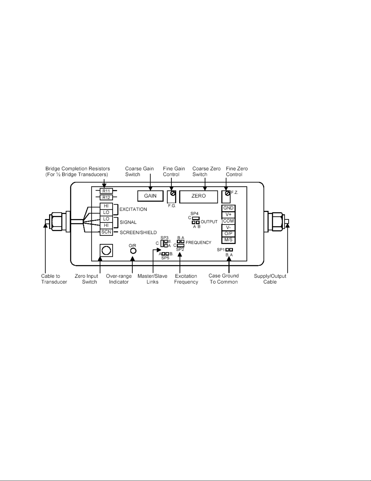
2.2 Connections General
Transducer and supply/output connections are made via two screw-clamped terminal blocks mounted
on the circuit board adjacent to the two cable glands as shown in Fig.1.
DCM 482/2004 1
Page 4
To reverse output polarity, reverse Signal Hi/Signal Lo. With all supplies, voltage output is between
OUTPUT and COMMON, which is internally connected to Excitation Lo and Shield. For best results,
COMMON should be grounded. NEVER CONNECT COMMON TO V+ OR V-.
Note that when using single supply, the output common is referenced to approximately half the supply
voltage and should be monitored with a floating or differential input instrument with sufficient common
mode voltage range.
Current (4-20mA) output is between OUTPUT and V-.
WARNING: INCORRECT SUPPLY CONNECTION, e.g. CONNECTING SUPPLY WIRE TO
OUTPUT (O/P) MAY DAMAGE THE UNIT AND INVALIDATE THE WARRANTY.
Fig. 1 Control locations etc.
The G'ND terminal is connected to the case.
DCM 482/2004 2
Page 5

2.3 Typical supply/output connections
a) Voltage output, single supply (ensure SP1 is NOT linked, see fig. 1)
This arrangement should only be used if (c) is not possible. If this arrangement is used, either the
supply V- or the output common (or both) must be fully floating. Failure to do this may result in
damage to the amplifier that is not covered by warranty.
b) Current output, single supply (ensure SP1 is NOT linked, see fig. 1)
c) Voltage output, dual supply
d) Current output, dual supply
This arrangement should only be used if (b) is not possible.
If this arrangement is used output common (V-) must be fully floating. Failure to do this may result in
damage to the amplifier that is not covered by warranty.
Note 1 In a) and b) the COM (common) terminal floats at 1/2 the supply voltage
Note 2 Ground is connected to the case
DCM 482/2004 3
Page 6

2.4 Transducer connections (LVDT and half bridge)
Fig. 2a LVDT transducer connections.
See fig. 1 (or amplifier PCB) for pin designations.
Most Cooper LVDT transducers also have a BLACK wire. This is not required with the DCM 482
amplifier and should be insulated and left unconnected.
If the above configuration does not give the required output phase (i.e. the output rises for outward
transducer movement instead of falling); reverse signal high and signal low connections.
Fig. 2b Half bridge (differential inductance) transducer connections.
In addition to these connections, it is necessary to add two bridge completion resistors to compensate
for the fact that the transducer is only half bridge. For Cooper transducers, the resistors should be 1k
Ohms, high stability. These should be mounted in R11 and R12 locations, as shown in Fig. 1.
If when connected, the phase of the amplifier output is not as required (for example, an inward moving
armature causes a rising amplifier output when a falling output is required) then reversing the
excitation high and excitation low wires will correct this.
Fig. 3 Signal Cable Installation for Optimum ECM
1
DCM 482/2004 4
Page 7

2 Insert the end of the cable, plus the plastic sleeve into the metal outer shell of the gland. The bore
of the gland is a tight fit onto the cable shield, giving the required ground contact.
3 Fit gland cap and tighten
DCM 482/2004 5
Page 8

3. CONTROLS
(For locations, see Figure 1)
3.1 Voltage/Current Output
Solder link SP4 determines which output mode is available at the Output terminal 2 of the
supply/output connector. The unit is normally supplied linked for voltage output, i.e. SP4 A-C. For
current output change the link to B-C.
3.2 Coarse Gain Selection
Typically, transducer manufacturers' data sheets or calibration certificates will give a figure allowing
the full-scale output to be calculated. Possible formats for this are as follows; the examples assume
a transducer range of ±50mm.
Sensitivity format Explanation To convert to F.S. output
mV/V/mm
e.g. 46mV/V/mm
Millivolts of output, per volt
of excitation, per mm of
Sensitivity x 1 x range in mm
e.g. 0.046 x 1 x 50 = 2.3V
travel
V/V at full-scale,
e.g. 2.3 V//V
mV/mm at a specified
excitation voltage
E.g. 230mV/mm at 5V
Volt of output, per volt of
excitation, at full-scale
Millivolts of output, per mm
of travel, given a specified
excitation voltage.
Sensitivity x 1
e.g. 2.3 x 1 = 2.3V
(Sensitivity / specified excitation
voltage) x 1 x range in mm
e.g. (0.230/5) x 1 x 50=2.3V
exc.
The standard excitation of the DCM 482 is 1V, as used in the calculations above.
The following table shows the band of transducer full-scale output voltages appropriate to each of the
8 Gain Range Settings. For example, a transducer with a full-scale output of 2.3V would be correctly
set as gain range 3.
An 8-position slide switch setting the overall gain in the ranges shown below:
Switch
Position
Gain Range
(Approximate)
Recommended Input
For ±5V O/P For 4-20mA O/P
1 X0.07 to x0.25 4V max 4V max
2 0.25 to 0.7 4V max 4V max
3 0.7 to 2.5 2 – 4V max 1.7 – 4V man
4 2 to 6 0.8 – 2.5 0.7 – 2
5 5 to 20 0.3 – 1 0.22 – 0.8
6 17 to 50 0.1 – 0.3 0.07 – 0.25
7 50 to 170 0.03 – 0.1 0.02 – 0.08
8 170 to 500 0.01 – 0.03 -
3.3 Fine Gain
A screwdriver-adjusted, 20-turn potentiometer providing a 4:1 adjustment of gain, interpolating
between the ranges set by the GAIN RANGE switch.
DCM 482/2004 6
Page 9

3.4 Coarse Zero
A 9-position slide switch (position 10 not used) providing output zero shifts of about 1v per step (with
Fine Gain at minimum - up to 4v at maximum). When used with ZERO FINE will suppress any output
(up to 5v) to zero. Position 5 is normal, i.e. no suppression applied, 6
to 9 suppress negative outputs,
1 to 4 suppress positive outputs. Moving the slider in either direction away from 5 increases the
suppression.
3.5 Zero Input
A push-button switch, which, when pressed, zero’s the signal, input voltage to the amplifier
irrespective of transducer position. This enables a true amplifier zero to be realized.
3.6 Fine Zero
A screwdriver-adjusted, 20-turn potentiometer allowing adjustment of output zero by ±1v to ±4v
depending on Fine Gain setting. Used with 3.3 will provide up to 100% suppression.
3.7 Over-Range Indicator
A red lamp that indicates when the demodulator input exceeds the linear range.
3.8 Excitation Frequency
Units are normally supplied with link SP2 fitted A-C for 5kHz excitation. For 2.5kHz, change the link to
B-C.
Other frequencies may be selected by changing resistor R33 (on pins) where R(k) = 70 / f(kHz), e.g.
for 2kHz, R = 35k Note: If the frequency is reduced then output noise (ripple) will increase, e.g. for
2.5kHz, 15mV; and 1kHz, 900mV peak to peak.
3.9 Master/Slave
The module may be configured as a master oscillator or slave oscillator via solder links
SP3 and SP5.
For Master oscillator link SP3 B-C and SP5 A-B.
For Slave units, link SP3 A-C and remove SP5.
Link the M/S terminal of the supply/output connector of all modules as shown below:
Normally, units are supplied as masters with SP3 linked B-C and SP5 linked A-B, although for a
stand-alone unit, SP3 is not essential.
DCM 482/2004 7
Page 10

4.0 SETTING UP PROCEDURES
4.1 LVDT & Half Bridge (Differential Inductance) Transducers
4.1.1 Determine the transducer output from the manufacturer's data sheet (See Section 4 for
Cooper LVDT transducer outputs) and set the Coarse Gain control as shown in Sections 3 and 4.
4.1.2 Connect the transducer to the 5-way connector as detailed in Section 2. Switch ON power and
allow a 15-minute warm-up period (for maximum accuracy).
4.1.3 Press the ZERO/INPUT switch and adjust the ZERO controls for zero output as
shown in Section 3. (For 4-20mA outputs, "zero output" = 12mA). Release the switch.
4.1.4 Adjust the transducer armature for zero output (12mA). The FINE ZERO control
may be used to obtain an absolute zero indication if the armature adjustment is too coarse.
Now proceed with either 4.15 or 4.16 according to application.
4.1.5 Bipolar Operation (e.g. ±10V)
(a) Move the transducer armature by a precise amount (e.g. 0.200 inches for a D5/200
transducer) and adjust the FINE GAIN control for the desired output, e.g. 5v, or 20mA.
(b) Relocate the transducer armature at the center of the stroke and check that the output is zero.
Re-adjust the FINE ZERO control if necessary.
Repeat (a) and (b) for consistent results.
(c) Move the armature to the full-scale position in the opposite direction and check for example -
5v or 4mA output.
4.1.6 Unipolar Operation (e.g. 0 to 10V)
If it is required that the transducer be used over its entire working range in the one direction, e.g. 0 to
0.4 inches for a D5/200 transducer, then the zero controls are used to "back-off" the signal equivalent
to 0.200 inches.
Move the armature by exactly 0.200 inches (for a D5/200 transducer) and then adjust the ZERO
controls to back off this signal to zero (or 12mA). Now move the armature back 0.400 inches and
adjust the FINE GAIN control for the required output.
DCM 482/2004 8
Page 11

DCM 482/2004 9
Page 12

5. SPECIFICATION
DCM 482/2004 10
Page 13

6 WARRANTY AND SERVICE
WARRANTY
Cooper Instruments products are warranted against defects in materials or workmanship. This
warranty applies for one year from the date of delivery. We will repair or replace products that prove to
be defective during the warranty period provided they are returned to Cooper Instruments. This
warranty is in lieu of all other warranties, expressed or implied, including the implied warranty of
fitness for a particular purpose to the original purchaser or to any other person. Cooper Instruments
shall not be liable for consequential damages of any kind. If the instrument is to be returned to Cooper
Instruments for repair under warranty, it is essential that the type and serial number be quoted,
together with full details of any fault.
SERVICE
We maintain comprehensive after-sales facilities and the instrument can, if necessary be returned to
our factory for servicing. Equipment returned to us for servicing, other than under warranty, must be
accompanied by an official order as all repairs and investigations are subject to at least the minimum
charge prevailing at the date of return. The type and serial number of the instrument should always be
quoted, together with full details of any fault and services required.
IMPORTANT NOTES
1. No service work should be undertaken by the customer while the unit is under warranty except
with the authorization of Cooper Instruments.
2. If the instrument is to be returned to Cooper Instruments for repair, (including repair under
warranty) it is essential that it is suitably packed and that carriage is insured and prepaid.
Cooper Instruments can accept no liability whatsoever for damage sustained during transit.
3. It is regretted that the above warranty only covers repairs carried out at our factory. Should
the instrument have been incorporated into other equipment that requires our engineers to
perform the repair on site, a charge will be made for the engineer's time to and from the site,
plus any expenses incurred.
The aforementioned provisions do not extend the original warranty period of any product that has
been either repaired or replaced by Cooper Instruments.
THIS WARRANTY MAY BE NULL AND VOID SHOULD THE CUSTOMER FAIL TO MEET OUR
TERMS OF PAYMENT.
DCM 482/2004 11
 Loading...