

Page 1

DCM 480
LVDT SIGNAL CONDITIONING
MODULE
www.cooperinstruments.com
PH: 540-349-4746 • FAX: 540-347-4755
DCM 480/2004 1
Page 2

TABLE OF CONTENTS
1. INTRODUCTION ........................................................................................................ 1
2. INSTALLATION INSTRUCTIONS .......................................................................... 1
2.1 EMC Requirements................................................................................................... 1
2.2 Supply/Output Connections...................................................................................... 1
2.3 Transducer Connections............................................................................................ 2
3. CONTROLS .................................................................................................................. 5
3.1 Coarse Zero Switch................................................................................................... 5
3.2 Fine Zero Potentiometer ........................................................................................... 5
3.3 Zero Input Switch ..................................................................................................... 5
3.4 Span Switch (Coarse gain)........................................................................................ 5
3.5 Fine Span Potentiometer........................................................................................... 6
3.6 Filter Switch.............................................................................................................. 6
4. SETTING UP PROCEDURE............................................................................. 7
4.1 Bipolar or Half-stroke Applications.......................................................................... 7
4.2 Offset Stroke Applications........................................................................................ 7
5. SPECIFICATION......................................................................................................... 8
6. WARRANTY AND SERVICE .................................................................................... 9
DCM 480/2004 ii
Page 3

1. INTRODUCTION
The DCM 480 is a two-wire, 4-20mA-output oscillator/demodulator for use with LVDT
transducers having suitable primary impedance. (Refer to sect 5).
Coarse and Fine controls for gain and zero (4mA) allow use with the full range of Cooper
transducers and a filter switch allows selection of optimum bandwidth/noise. The
differential signal amplifier circuit allows the use of long transducer cables.
The two-wire supply/output system allows use with long cables from the supply/monitor
with a wide range of supply voltage and high noise immunity.
In order to meet the primary impedance requirements of the DCM 480, some Cooper
transducers are modified to TM202. Section 2.4 refers.
Note: The DCM 480 is not suitable for use with differential or half-bridge transducers.
2. INSTALLATION INSTRUCTIONS
2.1 EMC Requirements
For EMC compliance, good quality shielded cable should be used for connection to this
instrument. The shields of both transducer and 4-20mA loop cables should be
connected as shown in Fig. 4.
• Note 1-Cable shields to be grounded at only one end - the instrument end.
• Note 2-When the instrument is a small part of a large electrical installation,
ensure the cables to and from the instrument are segregated from electrically
noisy cables.
• Note 3-Ensure cables to and from the instrument are routed away from any
obviously powerful sources of electrical noise, e.g. electric motors, relays,
solenoids.
• Note 4-ESD precautions should be used when working on the instrument circuit
board with the lid removed. The user should ensure he is "grounded" by use of a
wrist strap or at least touching ground before touching any component including
wires, terminals or switches.
• Note 5-The body of the transducer and the DCM 480 case should be grounded.
If the transducer fixing attachments do not provide a good ground, then a ground
strap should be used.
2.2 Supply/Output Connections
The two wires from the supply/output monitor are connected to terminals 6 and 7
Polarity of supply is irrelevant as a reverse polarity protection circuit automatically
energises the oscillator/demodulator with the correct polarity.
DCM 480/2004 1
.
Page 4
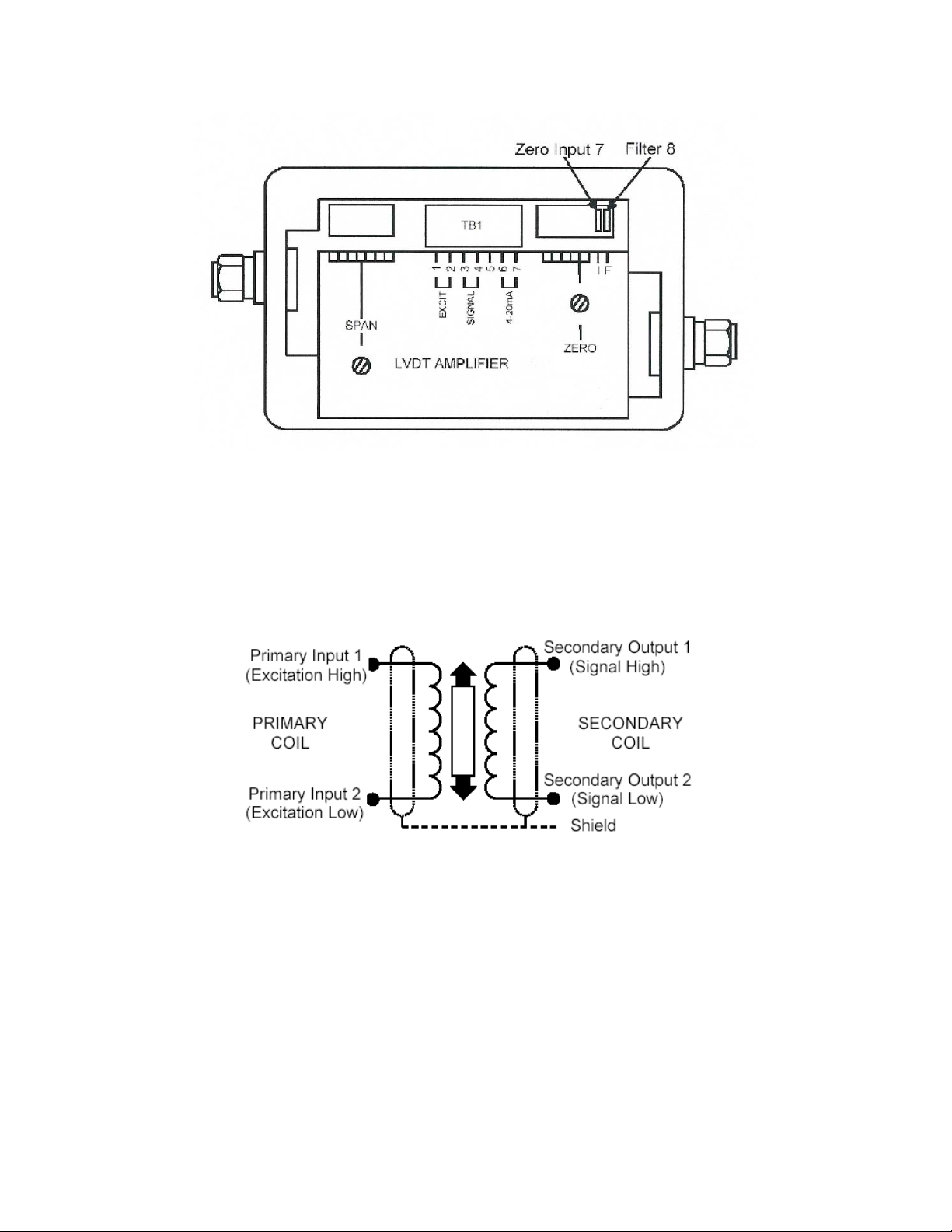
2.3 Transducer Connections
Fig. 1 General view of DCM 480
Fig. 2 Connection for LVDT Transducers
Function TB1 PIN
Excitation Hi Excit 1
Excitation Lo Excit 2
Signal Hi Signal 3
Signal Lo Signal 4
Shield Gland shell
(see Fig. 4)
Some Cooper LVDTs have a BLACK wire. This
must be insulated.
If when connected, the phase of the amplifier
output is not as required (for example, an
inward moving armature causes a rising
amplifier output when a falling output is
required) then reversing the signal high and
signal low wires will correct this.
DCM 480/2004 2
Page 5

DCM 480 Case
Fig. 3 Connection Schematic
DCM 480/2004 3
Page 6

DCM 480/2004 4
Page 7

3. CONTROLS
Please refer also to Fig. 1 for locations. The locations of all controls are also shown on
the legend plate mounted on the PCB.
3.1 Coarse Zero Switch
The toggles or levers 1 to 6 of an 8-way DIL switch are used to inject varying amounts of
offset into the output signal circuit. This, together with the Fine Zero Potentiometer,
allows aligning the 4mA output point to coincide with any desired armature position. For
example, an ACT1000 can be made to give a 4-20mA output with a stroke of -0.5in. to
+1in., etc.
The amount of offset for each lever setting is shown below:
Lever On mA Output Shift (approx.)
1 -7
2 -5
3 -3
4 -2
5 +2
6 +3
3.2 Fine Zero Potentiometer
This control is used together with the coarse zero switch to set the 4mA output level.
Refer also to Section 3.1. Avoid applying excessive tightening force to the locking nut.
3.3 Zero Input Switch
Toggle/lever 7 of the Zero Switch, when set to ON, zeroes the amplifier input signal
irrespective of the transducer position. This simulates the transducer mid-stroke (zero
output) signal and may be used to set the mid-range output level (e.g. 12mA) or
transducer mid-stroke position without disconnecting the transducer secondary.
3.4 Span Switch (Coarse gain)
This is an 8-toggle/lever DIL switch which, when used with the Fine Span control, allows
a 4-20mA output to be obtained with a wide range of transducer signals. Typically,
transducer manufacturers' data sheets or calibration certificates will give a figure
allowing the full-scale output to be calculated. Possible formats for this are as follows;
the examples assume a transducer range of ±50mm.
DCM 480/2004 5
Page 8

Sensitivity format Explanation To convert to F.S. output
mV/V/mm
e.g. 46mV/V/mm
V/V at full-scale,
e.g. 2.3 V//V
mV/mm at a specified
excitation voltage.
E.g. 230mV/mm at 5V
exc.
Millivolts of output, per volt of
excitation, per mm of travel
Volt of output, per volt of
excitation, at full-scale
Millivolts of output, per mm
of travel, given a specified
excitation voltage.
Sensitivity x 0.5 x range in mm
e.g. 0.046 x 0.5 x 50 = 1.15V
Sensitivity x 1
e.g. 2.3 x 0.5 = 1.15V
(Sensitivity / specified
excitation voltage) x 0.5 x
range in mm
e.g. (0.230/5) x 0.5 x 50=1.15V
The standard excitation of the DCM 480 is 0.5V for mod 6 onward, as used in the calculations
above.
The following table shows the band of transducer full-scale output voltages appropriate
to each of the 8 Gain Range Settings. For example, a transducer with a full-scale output
of 1.15V would be correctly set as gain range 2.
The table below shows the V r.m.s. signals required for full
output with the Fine Span either at minimum or maximum:
Lever On
2 to 4 1
1-2 2
0.7-1 3
0.4-0.7 None
0.25-0.44 4
0.15-0.25 5
0.1-0.15 6
0.05-1 7
0.03-0.05 8
3.5 Fine Span Potentiometer
This control interpolates between the ranges of the Span switch. (Section 3.4).
Avoid applying excessive tightening force to the locking nut.
3.6 Filter Switch
Toggle/lever 8 of the "zero" DIL switch is used to select the bandwidth/noise
performance as shown in the specification:
DCM 480/2004 6
Page 9

4. SETTING UP PROCEDURE.
4.1 Bipolar or Half-stroke Applications
1. Connect the transducer and supply as shown in Section 2.
2. Select the relevant gain range by setting the Coarse Span switch as shown in
Section 3.4. Refer also to the transducer data to determine the input signal.
3. Set Zero Input lever to ON, all other Zero levers to OFF.
4. Adjust Fine Zero potentiometer for 12mA output.
5. Reset Zero Input lever to OFF and adjust the transducer armature for 12mA
output. This determines the transducer center stroke position.
6. Move the armature to the required full-scale position and adjust Fine Span for
20mA output. (Note: primary or secondary connections may be reversed to
reverse the output polarity.)
7. Move the armature to the required zero position (an equal but opposite
displacement to that in step 6) and check the output is 4mA. Trim Fine Span and
zero if necessary for optimum linearity over the 4-20mA range.
4.2 Offset Stroke Applications
1. Carry out steps 1 to 5 in Section 4.1, then: -
2. Move the armature to the desired half-stroke position and use the Coarse Zero
switch to suppress the output to near 12mA (refer to Section 3.1). Trim for
exactly 12mA via Fine Zero.
3. Move the armature to the desired full-scale position and adjust Fine Span for
20mA output.
4. Repeat steps 2 and 3 for consistent results.
5. Move the armature to the desired 4mA position and check for 4mA output.
DCM 480/2004 7
Page 10

5. SPECIFICATION
(Note: all figures are typical values)
Supply Voltage
Output regulation
Loop Resistance (Max)
(Min)
Output regulation
Excitation 0.5V rms. 5kHz sinusoidal at 4mA max.
Signal Range 30mV to 4V
Zero Range ±8mA
Linearity 0.05%
Bandwidth
Filter ON
Noise
Filter ON
Zero Temperature Coefficient
Gain Temperature Coefficient
Maximum Output Overload 45mA
EMC Performance When subjected to radiated electromagnetic energy
Operating Temperature -20 to 85°C (to 100°C possible)
Dimensions 125 x 80 x 57mm (4.7 x 3.2 x 2.1 inches)
Weight 550g (1.2lb)
Seal To IP65
Gland Cable Diameter 3 to 6.5mm (0.12 to 0.26 inches)
Note 1 The maximum allowable total external circuit
Note 2 Where the supply voltage is higher than 24 volts and
12 to 36V dc universal polarity
1µA/V
50 (12V) to 1200 (36V). See Note 1 below
See Note 2 below
2µA/100
250Hz flat
25Hz
50µA peak-peak
15µA peak-peak
0.005% FS/°C
0.015% FS/°C
(as IEC 801-3) an additional error can occur at
certain spot frequencies:
Field Strength
30V/m 0.5mA
3V/m 0.25mA
resistance is calculated from:
R max = 50(Vs – 11)
the ambient temperature higher than 25°C, then a
minimum value of loop resistance is required:
R min = (Vs – 28)(t – 25)
Where Vs = supply voltage (volts) and t = ambient
temperature (°C)
E.g. at 36 volts supply and 85°C ambient, the value
of RL must be between 480 ohms and 1200 ohms.
Typical Max. Error
DCM 480/2004 8
Page 11

6. WARRANTY AND SERVICE
WARRANTY
Cooper Instruments & Systems products are warranted against defects in materials or
workmanship. This warranty applies for one year from the date of delivery. We will
repair or replace products that prove to be defective during the warranty period provided
they are returned to Cooper Instruments & Systems.
This warranty is in lieu of all other warranties, expressed or implied, including the implied
warranty of fitness for a particular purpose to the original purchaser or to any other
person. Cooper Instruments & Systems shall not be liable for consequential damages of
any kind.
If the instrument is to be returned to Cooper Instruments & Systems for repair under
warranty, it is essential that the type and serial number be quoted, together with full
details of any fault.
SERVICE
We maintain comprehensive after-sales facilities and the instrument can, if necessary,
be returned to our factory for servicing.
Equipment returned to us for servicing, other than under warranty, must be accompanied
by an official order as all repairs and investigations are subject to at least the minimum
charge prevailing at the date of return.
The type and serial number of the instrument should always be quoted, together with full
details of any fault and services required.
IMPORTANT NOTES
1. No service work should be undertaken by the customer while the unit is under
2. If the instrument is to be returned to Cooper Instruments & Systems for repair,
3. It is regretted that the above warranty only covers repairs carried out at our
warranty except with the authorization of Cooper Instruments & Systems.
(including repair under warranty) it is essential that it is suitably packed and that
carriage is insured and prepaid. Cooper Instruments & Systems can accept no
liability whatsoever for damage sustained during transit.
factory. Should the instrument have been incorporated into other equipment that
requires our engineers to perform the repair on site, a charge will be made for the
engineer's time to and from the site, plus any expenses incurred. The
aforementioned provisions do not extend the original warranty period of any
product that has been either repaired or replaced by Cooper Instruments &
Systems.
DCM 480/2004 9
 Loading...