

Page 1

DCM 162
BRIDGESENSOR
USER’S GUIDE
www.cooperinstruments.com
PH: 540-349-4746 FAX: 540-347-4755
Page 2

CONTENTS
Features....................................................................................................................................... 1
Description.................................................................................................................................. 1
DCM 162 vs. DCM 160 ................................................................................................................ 1
DCM 162 Schematic.................................................................................................................... 1
Specifications ............................................................................................................................. 2
Functional Description............................................................................................................... 3
Instrumentation Amplifier .......................................................................................................... 3
Active Filter ................................................................................................................................. 4
Bridge Supply ............................................................................................................................. 5
Half Bridge Completion/Bridge Balance................................................................................... 5
General Calibration Procedures................................................................................................ 5
Application Examples ................................................................................................................ 6
Mechanical Specifications ......................................................................................................... 7
Warranty Repair Policy .............................................................................................................. 8
CF 118 ii DCM 162 - 4/2001
Page 3
Features
• Pin for Pin Replacement for DCM 160.
• Compact, complete and convenient to use
• Easy access to all trim adjustments
• Half Bridge applications made easy by Internal Completion Resistors
• On card Bridge Balance Trimpot eliminates additional wiring for Three Wire applications
• Changing Bridge supply voltage is easy using on board trimpot with adjustment range from +4 to +10 VDC
• Bridge supply lead resistance effects can be ignored with built-in remote sensing
• Filter frequency can be changed with the flick of a DIP switch
Description
The DCM 162 Bridgesensor is a complete signal conditioning system on a card designed expressly for either half or
full bridge transducers. The DCM 162 consists of a high performance instrumentation amplifier, a user adjustable
active filter, high stability bridge supply and all of the required circuitry, trimpots, etc., so that only point to point wiring need be made to the inputs, outputs and power to have a complete signal conditioning system up and running.
The mounting kit provides coarse and fine gain adjustment trimpots along with input and output offset adjustments,
DIP switches for setting the bridge supply output and active low pass filter cutoff frequency.
Application of the DCM 162 is easy by following the detailed applications information that is included with this data
sheet and full engineering specifications allow easy and complete worst-case analysis.
DCM 162 vs. DCM 160
The Model DCM 162 is a pin compatible replacement for the DCM 160, which is no longer available. The one
major difference is that the DCM 162 does not have a reference voltage on pin J. Pin J has no connection. The
DCM 162 also has a high frequency input filter to reduce EMI. This filter has a high frequency cutoff above
200KHz, which is well above the requirements of weighing systems. See Figure 3 DCM 162 Input Amp Response.
The output of the instrumentation amplifier, pin P, is not inverted with respect to the Filter Output as it was in the
DCM 160. The output offset pot, RP1, is disabled by a jumper, J1, which must be removed to use RP1. The
external output offset input, pin K, is always active.
Applications using the DCM 160 can use the DCM 162 simply by inserting the board and making the typical zero
and span adjustments. No wiring changes should be required.
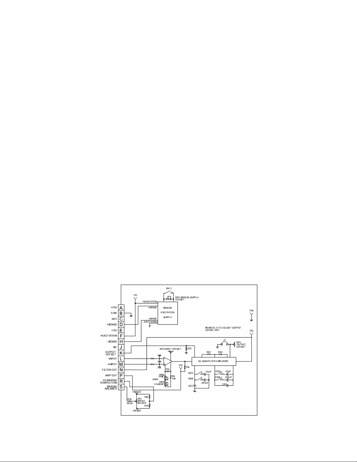
DCM 162 Schematic
Figure 1. Complete schematic of the DCM 162 Bridgesensor
CF 118 1 DCM 162 - 4/2001
Page 4

Specifications
Conditions (Unless Noted): Ta = 25°C, Vs = ±15 VDC, G = 500 V/V
Amplifier (1)
Gain Range Adjustable (2)
w/External Set Resistor
Gain Equation Rg= 100,000/(G-2) ohms
Gain Equation Accuracy 2 <G<1000 V/V 3 %
Gain Temperature w/Trimpots
Coefficient Amplifier alone
Nonlinearity, ±10V Output Swing 0.002 0.005 %
Offset Voltage, Input and Output Adjustable to Zero
Warmup Drift (3) ±1 ±5 µV
Input Offset
Vs. Temperature: G=2V/V
G=1000V/V
At Other Gains, Max.
Vs. Power Supply
Output Offset Adjust Range ±10 V
Input Bias Current (4)
Vs. Temperature
Input Offset Current
Vs. Temperature
Input Impedance (5) 4G ohms II .0047 µF
Common Mode Range, Linear Response
Input Voltage: Maximum
CMR (6): 1 kHz bw, DC-60 Hz (7)
10 kHz bw, DC-60 Hz (7)
Input Noise Voltage: 0.1 Hz-10 Hz
10 Hz-100 Hz
Current: 0.1 Hz-10Hz 80 pA P-P
Rated Output: Voltage, 2 kohm Load
Current
Load Capacitance
Short Circuit
Dynamic Response (8): Small Signal Bandwidth
Amp Response (see figure 3)
Low Pass Filter (9): Number of Poles
DC Gain (Pin P to N)
Roll Off
Bridge Excitation Supply (10)
Output Adjustment Range: w/Trimpot 4 10 VDC
Output Current 0 120 mA
Load Regulation =0-120 mA 0.02 0.05 %
Line Regulation Vin=14.5-16 VDC 0.005 0.01 %/V
Stability (11): Short Term
Long Term
Vs. Temperature
Warm-up Drift
Short Circuit Protection Short Term-10 minutes
Output Noise, 10 Hz-1kHz 200 µV P-P
Half Bridge Completion
Nominal Resistance Value 10 kohms
Initial Accuracy 0.1% %
Temperature Tracking 5 ppm/ºC
Balance Adjustment Range, 350 ohm Bridge ±15 mV
Power Requirements
Voltage: Rated Performance
Operating
Current (12) ±12 mA
Environmental
Ambient: Operating
Storage
Notes:
(1) Specifications referred to the filter output (Pin N).
(2) Using on board coarse and fine gain adjust trimpots.
(3) Warm-up drift is specified as the input offset drift for the first 5 minutes after the application of power with G = 1000 V/V, Bridge supply =
10V driving a 350 ohm bridge.
Parameter Minimum Typical Maximum Units
100
2
75
1
1
±9
100
0.3
±10
±5
Adjustable kHz
2
0.05
±13
-25
-40
500
25
±2
±0.2
±0.2 ±(20/G)
±1
40
40
±15
120
1
1 minute
+2
40
0.2
40
0.01
±15
55
5000
150
100
±10
±1
±5
5 nA
5 nA
VDC
dB
µV P-P
1000
80
±16
80
V/V
Ppm/ºC
µV/ºC
µV/V
pA/ºC
pA/ºC
VDC
mA
pF
V/V
dB/Dec
%/24 Hrs
%/kHrs
ppm/ºC
%
VDC
ºC
CF 118 2 DCM 162 - 4/2001
Page 5

(4) Measured at 25°C Ambient with unit fully warmed up.
(5) Measured from -Input to +Input or input with respect to ground.
(6) Specified with 350-ohm bridge as source impedance.
(7) Filter frequency set with DIP switches.
(8) Small signal response, switch or resistor/capacitor selectable, see applications section.
(9) The low pass filter cutoff frequency is adjustable to 10, 100 and 1000 Hz using the onboard DIP switches and from 1 Hz to 10 KHz using
external resistors and capacitors.
(10) Bridge supply must be operated with +Sense connected to the Bridge Supply Pin and with -Sense connected to Common.
(11) Stability is defined after a 5-minute warm-up period and with constant line, load and ambient temperature unless otherwise specified.
(12) Quiescent current for amplifiers only, the current drawn from the bridge supply must be added to the +15 VDC current drain for total current
draw.
Functional Description
The DCM 162 is a completely self-contained single channel signal conditioning system on a card. This device offers
the high performance and reliability of surface mount circuitry with the completeness of a mounting kit containing all
trimpots and components needed for operation. All that needs to be added is power and transducer inputs to get a
conditioned output suitable for driving A/D converters, panel meters, indicators, or PC based controllers.
Instrumentation Amplifier
The heart of the DCM 162 is the high performance instrumentation amplifier. This amplifier features low noise, low
drift and high accuracy along with trimpot adjustments for coarse/fine gain and input offset voltage. The direct
instrumentation amplifier output is brought out to Pin P on the
output is also brought out to the test point AMP OUT at the trimpot edge of the mounting kit. The trimpots allow a
gain adjustment range of 100 to 500 V/V with a coarse and fine gain adjuster (clockwise rotation increases gain). A
user-supplied resistor can be used in place of the trimpots (see equations below) to get any gain from 2 to 5000V/V
(referred to filtered output). To use an external resistor remove R6 from the mounting kit to disable the trimpots,
then calculate the required value for RG and solder it on the mounting kit in the spot provided.
The gain equation accuracy is ±3 percent for gains from 2 to 1000 V/V.
RG =
100,000
Equation 1: User supplied resistor value required to set gain with respect to Pin N, filtered
RG =
50,000
Equation 2: User supplied resistor value required to set gain with respect to Pin P, amplifier direct output. NOTE: If
a fixed resistor is used for RG, then resistor R6 should be removed from the 162MK to disable the gain trimpots. If
a slightly higher RG is used, the pots and R6 can be used to provide a small
Example Resistor Values for Common Gains (to Filtered Output):
Required Gain,
Filtered Output
10 12,400 ohms
100 10,200 ohms
333.33 301 ohms (Use for 3mV/V Transducers)
500 205 ohms (Use for 2mV/V Transducers)
1000 100 ohms
Note: A high stability, 5 ppm/ºC metal film resistor should be selected for RG for maximum performance.
The instrumentation amplifier also has a trimpot adjustment for input offset voltage, this trimpot should be used to
null the instrumentation amplifier offset only. System offsets should be adjusted out using the Bridge Balance or
the Output Offset feature (see applications section for more information) to retain minimum offset drift of the
instrumentation amplifier.
The DCM 162 inputs should be placed as close to the transducer as possible. This will minimize any possible
pickup of electrostatic or electromagnetic noise into the very high impedance inputs. See the applications section
for more information on shielding methods.
DCM 162, through a 100-ohm isolation resistor. This
G-2
G-1
Ohms
Ohms
adjustment range.
RG Value
CF 118 3 DCM 162 - 4/2001
Page 6

Active Filter
The output of the instrumentation amplifier is connected to the input of a 2 pole, active filter with a gain of 2. This
filter has an adjustable filter cutoff frequency of 10, 100 and 1kHz by the use of on board DIP switches and can be
set to any frequency from 10 Hz to 10 kHz by the use of user supplied resistors and capacitors. The filtered output
is brought out to Pin N and to test point FILTER OUT at the trimpot end of the board on the DCM 162. Pin N is the
standard output for most strain gage and instrumentation applications. By using the filtered output extraneous noise
above the useful signal frequency is removed at a rate of 40dB/decade above the filter cutoff frequency allowing
very precise and low noise measurements to be made. Figure 2 details the DIP switch settings and the equations
required to set the filter cutoff to any other frequency.
The filter stage is also the input for the output offset voltage adjustment. The output offset may be adjusted with the
on board trimpot or by driving the output offset input (Pin K) with a low impedance source or the wiper of a trimpot.
NOTE: to use the on-board offset pot, J1 must first be removed. The gain from the External Output Offset pin (Pin
K) to the filtered output (Pin N) is approximately 1 V/V (i.e. if Pin K is changed by 1 Volt in a positive direction then
Pin N will also change by 1 Volt in a positive direction).
If pin K is used as the Output Offset control, than J1 should be installed to prevent interaction of RP1.
Filter Cutoff Frequency Adjustment
Cutoff Frequency SW2 SW3 SW4 SW5
10 Hz ON ON
100 Hz ON ON
1000 Hz
or User Select
CX1 = CX2 = 0.0024 µF
1000
Fc
CUTOFF FREQUENCY > 1000 hZ
RX1 = 35,000/
RX2 = 105,000/
1000
1000
ALL OFF
-1
Fc
Fc
-1
-1
Built in low pass filter frequency response
FIGURE 2. Dip switch settings and equations required to set the filter cutoff frequency.
CF 118 4 DCM 162 - 4/2001
Page 7

Figure 3. DCM 162 Input Amp Response
Bridge Supply
The bridge excitation supply is a very well regulated low noise output designed to drive either full or half bridge
transducers from 0 to 120mA output current. The output can be set to a fixed +10V by setting DIP switch SW1 ON.
By setting SW1 OFF the output can be adjusted from +4 to +10Volts by adjusting the bridge supply adjust trimpot.
The bridge supply uses + and - sense connections to compensate for any line drops that might be present when
using remote transducers. See the applications examples for more information on properly using the + and - sense
pins. If remote sensing is not required connect +Sense (Pin D) to Bridge Supply (Pin F) and -Sense (Pin H) to
Common (Pin B) directly at the mounting kit socket. The maximum voltage difference between the Bridge Supply,
Pin F and the +Sense, Pin D, is 0.4V.
Half Bridge Completion/Bridge Balance
Two 10K ohm thin film resistors are connected to the excitation supply sense lines and their center connection is
brought out to pin R. These resistors have a low temperature coefficient and track to 5 PPM/°C. This circuit can be
used as the other half of a Half Bridge transducer to provide a common mode voltage to the instrumentation
amplifier. Pin R can be connected to either the + or - input pin, depending on the polarity of the transducer output
signal.
A Bridge Balance circuit is also provided. RP6, BAL ADJ, is also connected across the excitation sense leads and
its swinger is brought out to Pin S through R18. With pin S connected to the same amplifier input as a 350-ohm Half
Bridge transducer, a bridge balance range of ±50% is available. Alternately, pin S can be connected to the Bridge
Completion resistors. However, in this case R18 should be increased to 1 megohms to reduce the sensitivity of the
adjustment. The Bridge Balance pin can be connected to either input when a Full Bridge transducer is used.
General Calibration Procedures
The DCM 162 comes from the factory adjusted to the following specifications:
GAIN 333 V/V
INPUT OFFSET Adjusted to 0, ±2mV
OUTPUT OFFSET J1 Installed
BRIDGE SUPPLY SW1 CLOSED, Bridge
Output at +10 Volts
FILTER SW2 - SW5 OFF, Filter at 1
kHz
BRIDGE BALANCE Pin S at 0 Volts
When adjusting the DCM 162 to other values the following methodology should be used:
Ground the inputs, set the input offset trimpot to get 0 Volts on the output you will be using (Pins N or P). Input
offset is for amplifier nulling only. Do not use the input offset for zeroing systems offsets, use the bridge balance or
the output offset adjustments for system offset correction.
Using a millivolt calibrator or the transducer output itself, set the gain so that the proper full scale output voltage is
realized (the mV calibrator or transducer should be set to simulate full scale output).
CF 118 5 DCM 162 - 4/2001
Page 8

If system offsets must be accounted for repeat step 1 again with the inputs disconnected from the source and
connected to ground, or short them together with the bridge connected, then reconnect the inputs and re-zero the
output with the bridge balance (if used).
Steps 1-3 above may need to be repeated several times to achieve the desired accuracy of gain and offset.
Application Examples
Figure 4. DCM 162 Trimpot Adjustment Detail
Figure 5. Full bridge with remote excitation sense
Figure 6. Full bridge with no remote sense
CF 118 6 DCM 162 - 4/2001
Page 9

Mechanical Specifications
Figure 7. Half Bridge
CF 118 7 DCM 162 - 4/2001
Page 10

Warranty Repair Policy
Limited Warranty on Products
Any Cooper Instruments product which, under normal operating conditions, proves defective in material or in
workmanship within one year of the date of shipment by Cooper will be repaired or replaced free of charge provided
that a return material authorization is obtained from Cooper and the defective product is sent, transportation
charges prepaid, with notice of the defect, and it is established that the product has been properly installed,
maintained, and operated within the limits of rated and normal usage. Replacement or repaired product will be
shipped F.O.B. from our plant. The terms of this warranty do not extend to any product or part thereof which, under
normal usage, has an inherently shorter useful life than one year. The replacement warranty detailed here is the
buyer’s exclusive remedy, and will satisfy all obligations of Cooper whether based on contract, negligence, or
otherwise. Cooper is not responsible for any incidental or consequential loss or damage which might result from a
failure of any and all other warranties, express or implied, including implied warranty of merchantability or fitness for
particular purpose. Any unauthorized disassembly or attempt to repair voids this warranty.
Obtaining Service under Warranty
Advance authorization is required prior to the return to Cooper Instruments. Before returning the item, contact the
Repair Department c/o Cooper Instruments at (540) 349-4746 for a Return Material Authorization number.
Shipment to Cooper shall be at buyer’s expense and repaired or replacement items will be shipped F.O.B. from our
plant in Warrenton, Virginia. Non-verified problems or defects may be subject to a $100 evaluation charge. Please
return the original calibration data with the unit.
Repair Warranty
All repairs of Cooper products are warranted for a period of 90 days from date of shipment. This warranty applies
only to those items that were found defective and repaired; it does not apply to products in which no defect was
found and returned as is or merely recalibrated. It may be possible for out-of-warranty products to be returned to
the exact original specifications or dimensions.
* Technical description of the defect: In order to properly repair a product, it is absolutely necessary for Cooper to
receive information specifying the reason the product is being returned. Specific test data, written observations on
the failure and the specific corrective action you require are needed.
CF 118 8 DCM 162 - 4/2001
 Loading...