

Page 1

XC/XPP/XST
Mechanical Force Gauges
User’s Guide
www.cooperinstruments.com
PH: 540-349-4746 • FAX: 540-347-4755
Page 2
MODELS
XC – with compression calibration
XST – with tension calibration
XPP - with compression/tension calibration
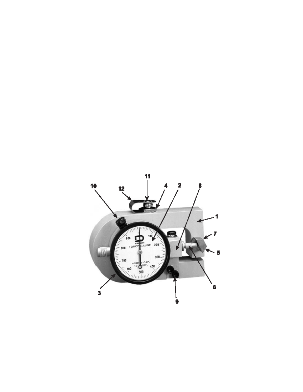
PRINCIPAL PARTS
For easy identification of Force Gauge parts*, the following illustration has been prepared. Correspondence with
our Service Department should refer to this illustration, and a rough pencil sketch of your particular setup will be
helpful.
1. “U” SHAPED DEFLECTION BEAM
2. DIAL INDICATOR
3. BEZEL (FOR ZERO ADJUSTMENT PURPOSES)
4. PRESSURE BUTTON
5. ANVIL
6. DIAL INDICATOR GAUGE MOVEMENT PLUNGER
7. ANVIL SET SCREW
8. DIAL INDICATOR MOUNTING BRACKET
9. MOUNTING BRACKET SCREWS
10. BEZEL LOCKING SCREW
11. LOADING BALL
12. SPRING RETAINER CLIP
* An optional MAXIMUM POINTER is available but not shown.
CF 109 1 11/02
Page 3

OPERATIONAL DATA
IMPORTANT!
When adjusting bezel-locking screw, #10, only tighten as much as is necessary to hold bezel in proper position.
DO NOT OVERTIGHTEN, as this will distort the thin housing of the dial indicator gauge; affect the smooth
action of the movement and produce false readings!
Your Force Gauge is ready to go to work for you without any special assembly. Upon removing it from the
storage case, it is only necessary to check the zero setting. This is done by placing the unit on a flat table with
the pressure button, # 4, at the top. Note that the dial bezel, # 3, is locked lightly by a knurled thumbscrew, # 10.
Simply loosen this knurled screw and then revolve the bezel in either direction, depending upon which way zero
may be off. Revolving the bezel causes the dial to follow. With zero positioned directly under the pointer tip,
again tighten the locking screw, and the instrument is ready to use.
Because of the sensitivity of the Cooper Gauge, zero should always be set with the unit resting on the lower or
thicker portion of the deflection beam as illustrated. This is the same position it occupies during calibration.
Ordinarily, zero will be retained indefinitely. However, under repeated stress or through accidental banging
around, it may go off slightly. Thus, it is a good plan to check zero occasionally.
Caution: The small anvil, #6, against which the dial indicator plunger rides, should never be altered except by
factory technicians. This anvil has nothing to do with zero setting. By careful adjustment, it has been positioned
in such a way that, for full load application within the range of the instrument, the pointer will revolve 360°.
TAMPERING WITH THE SETTING OF THIS ANVIL AUTOMATICALLY VOIDS THE ACCURACY
GUARANTEE. If the anvil should be accidentally thrown out of position by dropping or striking against another
object, the entire gauge should be returned to the factory for resetting and calibration check.
HELPFUL POINTERS
It is a good plan to test the tightness of the hardened dial indicator plunger, #6, occasionally. This part is
screwed into a finely threaded seat and may sometimes work loose. This would cause the gauge to read high
and might be mistaken for an off zero condition. Be sure not to force the plunger tip too tightly when screwing it
down since, as explained, the threads are fairly delicate and might break off.
Note that threaded mounting holes have been provided in opposite faces of the “U” shaped deflection beam, #1.
In the upper mounting hole, a spherically recessed pressure button, #4, is screwed. This button is hardened
and plated. It receives the loading ball, #11. Force should be applied directly against this ball. In operation, the
deflection beam bends inward slightly, and the ball revolves, tending to keep the line of force vertical. A drop of
light oil on the ball assists this action.
Never fasten the “U” shaped deflection beam in such a way that the free movement of the upper portion will be
retarded. The lower or thicker “leg”, however, may be tightened as securely as desired, using a stud or bolt
through the threaded mounting hole.
Since the deflection beam is hardened, it is not possible nor would it be recommended, to drill and tap it once it
is in the field. If special mounting holes are desired, these can be provided during early stages of manufacture,
but must be specified at that time.
If a particular test calls for load application through a pulley, roller or chuck, etc., due care should be taken to
see that the load is applied in a true vertical line through the center of the top-mounting hole #4. Off-center
loading would introduce leverage, thereby increasing or decreasing readings from their true value. Universal
joints or hinged fittings should be carefully machined to obviate side slop or play. If in doubt about the best
method of applying load for specific arrangement, don’t hesitate to consult our Engineering Department.
Remember, a rough pencil sketch or snapshot will aid tremendously in understanding your problem. Never oil
the dial indicator at any point. It is unnecessary. If oil or other fluids should get on the unit, wipe off gently, but
well. Foreign matter lodging on the plunger, #6 will retard its free action, resulting in inaccurate readings.
If accidental overload is anticipated, a solid steel rod about 3/4 inch in diameter can be inserted at the center
point of the Gauge between the “U” shaped bar. Length of this rod should be figured so that the upper, flexible
half of beam will bottom against it, once the full capacity of the instrument has been reached. Further load will
CF 109 2 11/02
Page 4

then pass through this solid path without harm to the Force Gauge. Note the method of mounting the dial
indicator to the supporting bracket on the reverse side of the case. Allen screws are used. Be sure to check
these screws at intervals, making sure that they are always tight. Vibration may in time loosen them slightly,
and it is best to take this precaution.
TENSILE MODEL
Generally speaking, the same requirements and suggestions applying to the compression model Force Gauge
also apply to the tensile unit. The main exception, of course, is that on the tensile model, load is applied through
the use of special end rod bearings.
Model XPP
These bearings are available for all tensile models as standard equipment. They are a perfect fit and without
any side play. Bearing pins can be machined from drill rod to suit your particular test plan. Remember that if
you require a special adapter of some kind in place of these bearings; be sure that such adapters are selfaligning so that applied force is always able to assume a vertical line.
Caution: Because there is the possibility that in service the ball-socket connectors can become unscrewed from
the beam, the operator should check these parts at intervals to make sure that some of the threaded shank is
ALWAYS showing on the inside of the “U” shaped beam. If it is not showing, no further loads should be applied
until the connector is screwed down to its normal position.
Do not attempt to weld, cotter pin, or otherwise make tensile connectors a solid part of the bar since every
requirement is different as to the length of the shank that has to be utilized. In summation, we must emphasize
that Cooper will not be liable for any incident that might result from accidental or intentional screw-out or break
away of the ball-socket connectors. For your own protection, keep these parts properly seated at all times.
Tare settings cannot be made on the Force Gauge without a slightly resultant loss in accuracy. This is due to
the fact that the dial layout is not 100% linear. Each unit is individually machined and thus must be individually
calibrated. While this makes for split-hair accuracy, division marks are not equidistant and hence do not lend
themselves to tare adjustment. Instead, any tare weight encountered in a typical test should simply be deducted.
CF 109 3 11/02
Page 5

WARRANTY REPAIR POLICY
Limited Warranty On Products
Any Cooper Instruments product which, under normal operating conditions, proves defective in material or in
workmanship within one year of the date of shipment by Cooper will be repaired or replaced free of charge
provided that a return material authorization is obtained from Cooper and the defective product is sent,
transportation charges prepaid, with notice of the defect, and it is established that the product has been properly
installed, maintained, and operated within the limits of rated and normal usage. Replacement or repaired
product will be shipped F.O.B. from our plant. The terms of this warranty do not extend to any product or part
thereof which, under normal usage, has an inherently shorter useful life than one year. The replacement
warranty detailed here is the buyer’s exclusive remedy, and will satisfy all obligations of Cooper whether based
on contract, negligence, or otherwise. Cooper is not responsible for any incidental or consequential loss or
damage which might result from a failure of any and all other warranties, express or implied, including implied
warranty of merchantability or fitness for particular purpose. Any unauthorized disassembly or attempt to repair
voids this warranty.
Obtaining Service Under Warranty
Advance authorization is required prior to the return to Cooper Instruments. Before returning the item, contact
the Repair Department c/o Cooper Instruments at (540) 349-4746 for a Return Material Authorization number.
Shipment to Cooper shall be at buyer’s expense and repaired or replacement items will be shipped F.O.B. from
our plant in Warrenton, Virginia. Non-verified problems or defects may be subject to a $100 evaluation charge.
Please return the original calibration data with the unit.
Repair Warranty
All repairs of Cooper products are warranted for a period of 90 days from date of shipment. This warranty
applies only to those items that were found defective and repaired; it does not apply to products in which no
defect was found and returned as is or merely recalibrated. It may be possible for out-of-warranty products to
be returned to the exact original specifications or dimensions.
* Technical description of the defect: In order to properly repair a product, it is absolutely necessary for Cooper
to receive information specifying the reason the product is being returned. Specific test data, written
observations on the failure and the specific corrective action you require are needed.
CF 109 4 11/02
 Loading...