

O W
N E R ' S M A N U A L
C&H A IR C O N D
ITI O
N E R S
GFH18K3BI
GFH24K3BI
GFH36K3BI
GFH48K3BI
GFH60K3BI
Split Air Conditioner
DUCT SERIES
MODELS:
Thanks for your selection of this Ducted Air-Conditioning Unit. Before use, please read this
instruction manual carefully and keep it properly to ensure correct use of this machine.

Safety Considerations
Please read this manual carefully before use and operate correctly as instructed in the manual.
1 You are specially warned to note the two symbols below.:
WARNING! A symbol indicating that improper operation might cause human death or severe
● This unit shall be used in offices, restaurants, residences or similar places.
● Please seek an authorized repair station for installation work. Improper installation might cause water leakage,
● Please install at a place strong enough to support the weight of air conditioner unit. If not, the air conditioner
● To ensure proper drainage, the drainage pipe shall be correctly installed according to installation instructions.
● Do not use or store flammable, explosive, poisonous or other dangerous substances beside the air conditioner.
● In case of trouble (e.g. burnt smell), please immediately cut off the main power of air conditioner unit.
● Keep air flow to avoid shortage of oxygen in the room.
● Never insert your finger or any objects into air outlet and inlet grill.
● Never plug or unplug the power cable directly to start or stop the air-conditioning unit.
● Please take constant care to check if the mounting rack is damaged after long use.
● Never modify the air conditioner. Please contact the dealer or professional installation workers for repair or
● The appliance shall not be installed in the laundry.
● Before installation, please check the power supply for compliance with the ratings on nameplate. Check the
● Before use, please check and confirm if the cables, drainage pipes and pipelines are correctly connected,
● Main power must be securely earthed to ensure effective grounding of air conditioner unit and avoid the risk
● Once started, the air conditioner shall not be stopped at least after 5 minutes or longer; otherwise the oil
● Do not let the child to operate the air conditioner unit.
● Do not operate the air conditioner unit with wet hands.
● Please disconnect the main power before cleaning the air conditioner or replacing the air filter.(Operating by
● Please disconnect the main power if to put the air conditioner unit out of use for a long period.
● Please do not expose the air conditioner unit directly under corrosive environment with water or moisture.
● Please do not foot on or place any goods on air conditioner unit.
● After electrical installation, the air conditioner unit shall be energized for electrical leakage test.(Operating by
● If the supply cord is damaged, it must be replaced by the manufacturer or its service agent or a similarly
● An all-pole disconnection switch having a contact separation of at least 3mm in all poles should be connected
● The appliance shall be installed in accordance with national wiring regulations.
● The temperature of refrigerant circuit will be high, please keep the interconnection cable away from the
WARNING!
electric shock or fire.
unit might fall down and cause human injury or death.
Take proper measures for heat preservation to prevent condensing. Improper installation of pipes might cause
leakage and wet the articles in the room.
relocation of the air conditioner.
power safety as well.(Operating by professinal)
hence to eliminate the risk of water leakage, refrigerant leakage, electric shock or fire.
of electric shock. Please do not connect the earthing cable to coal gas pipe, water pipe, lightning rod or
telephone line.
return to compressor may be affected.
professinal)
professinal)
qualified person in order to avoid a hazard .
in fixed wiring.
copper tube.
WARNING!
injury
A symbol indicating that improper operation might cause human property damage.
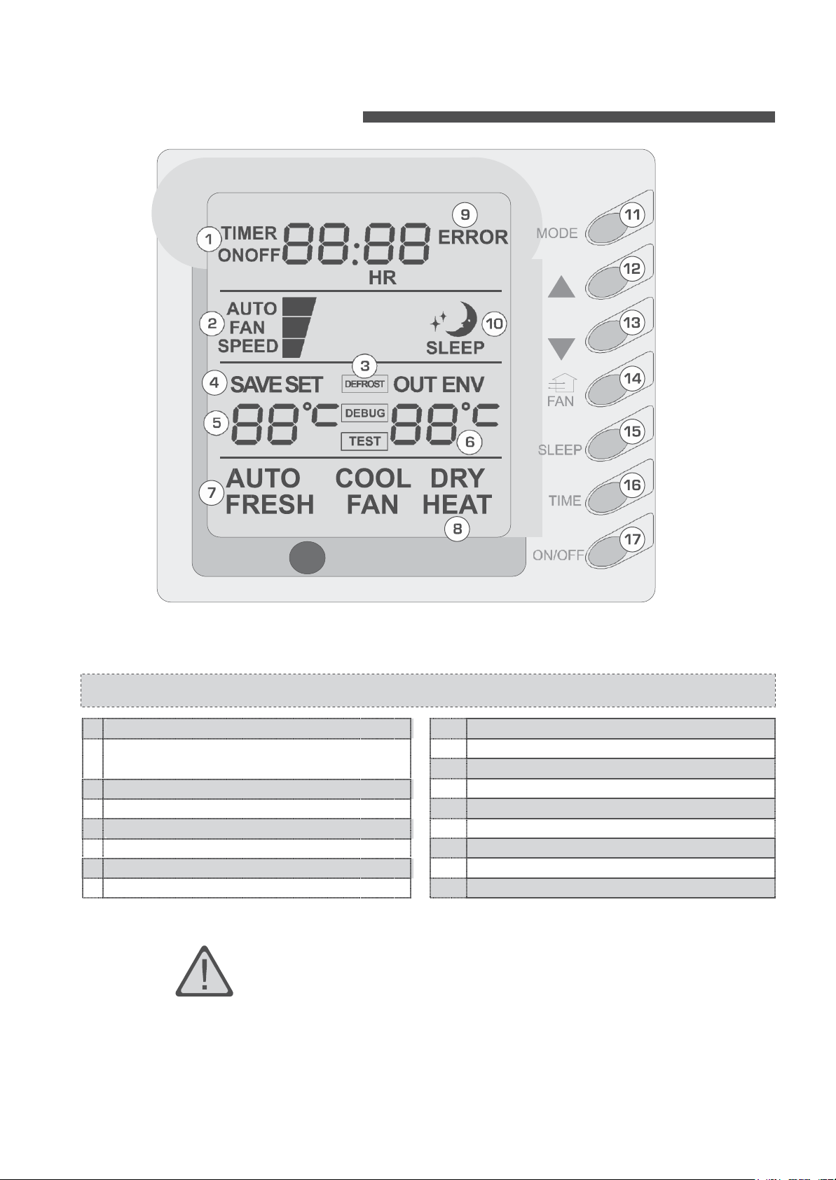
9
Failure st atus display
10
Sleep st atus display
11
Mode key
12
Se t temperatur e incr ease key
13
Se t temperatur e decr ease key
14
Fan speed key (fresh air setting)
15
Sleep key (outdoor environment temperatur
e check)
16
Timing key
17 ON/OFF key
1
Timing display
2
Fan speed display (Auto, High speed, Medium
speed, Low speed)
3
Defros ting st atus display
4
Ener gy saving st atus display
5
Se t temperatur e display
6
Ambient temperatur e display
7
Fr esh air st atus display (not supplied)
8
Mode (cooling, dehumidifying,fan, heating, auto)
Wire
controller (standard fitting)
Composition of wire controller
•
Never install the wire controller in a place where is water
• Avoid bunping, throwing, tossing
or frequently opening
leakage.
the
wire controller
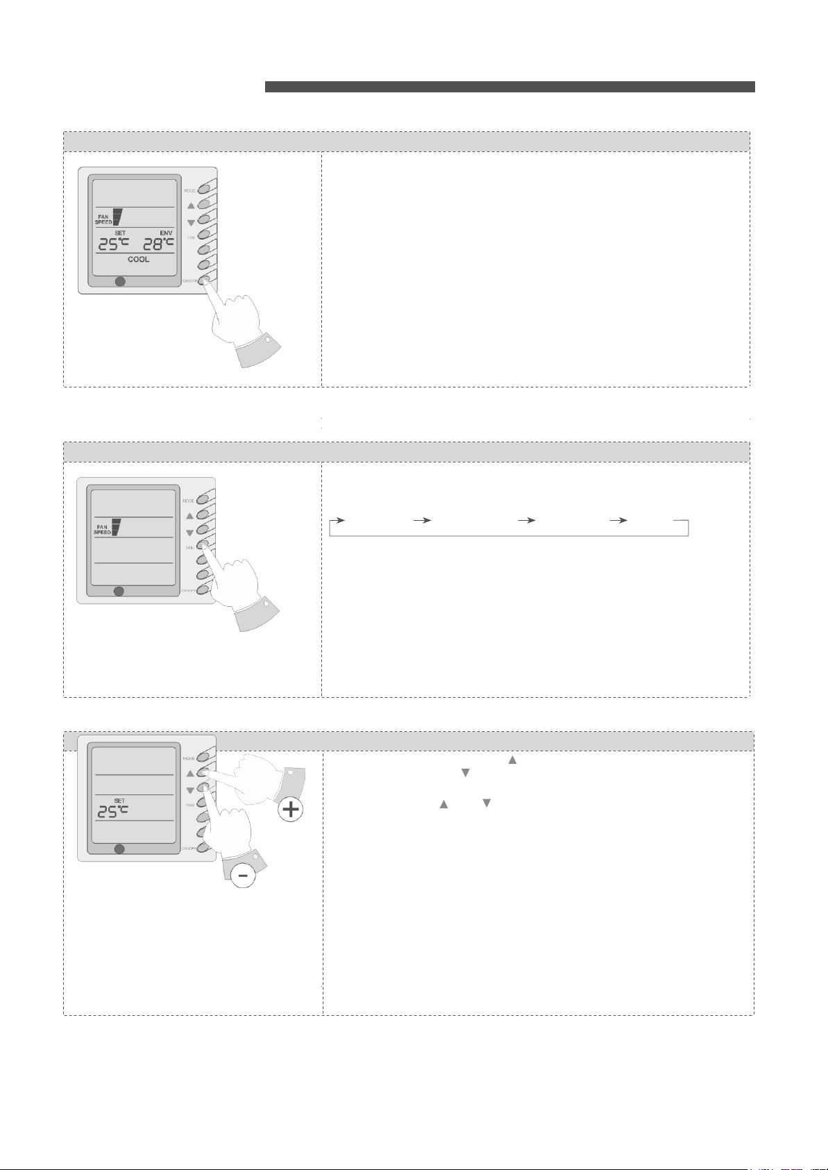
Oper
ating
Turning ON/OFF
unit
SW NG
TIMER
Pr
ess t he
ON/OFF key, then the unit shall start up. Press t he ON/OFF key
again, then the unit shall shut off.
Fan control (the figures show the relevant display ar
If
the fan control key is pressed
he following
Low
speed Medium speed High speed Auto
SWING
TIMER
In the dehumidifying mode: The fan speed shall be automatically se t
Temperature setting
SW NG
TIMER
Pr
ess the temper
tem
per
ature se
keys once, the temper
function: when the and key are pr
the se t temper
shall be shut
key lock function shall be re
monitor or centralized controller, the keys of the wire controller and the signal of
the remote
temperature indicating ar
under
various
Heating: 16 °C~ 30 °C Cooling: 16 °C
Dehumidifying1: 6 °C~ 30 °C
Fan: No temper
instructions
eas)
consecutively, the fan speed shall
sequence:
controller ar
modes:
ature se
tting key to decrease the set temper
atur
off;
atur
tting key to incr
atur
e shall increase or decrease by 1
e indicating are a shall display
press the two keys simultaneously for 5 second again, the
lea- sed. When the wire controller is locked by remote
e all locked and invalidated,
e a shall display
e setting function.
of
~ 30 °C
wire
ease the set temper
essed
“CC” Range of temperature setting
controller
changes
atur
ature (when pressing the
°C) NOTE:
simultaneously for 5 second,
“EE”
and all keys response
and then the se t
as per t
as lo
w
e; press the
key lock

Swing function setting
Sleep function
SWING
SWING
TIMER
setting
SWNG
TIMER
Press Swing button then the swing mode will be operated by the air conditioner.
Repress Swing button once to stop swing mode.
Note: There is no swing mode for duct type indoor unit
When under the cooling or dehumidifying mode, after receiving the
SLEEP order for 1 hour, the previous set temp. Set will be risen for
1°C, and another 1°C will be risen after 2 hours that means that the temperature
been risen 2°C within 2 hours. Then the unit will run according to this set temp.
When under the heating mode, after receiving the SLEEP order for 1 hour, the
previous set temp. Set will be lower for 1°C, and another 1°C will be lower after 2
hours that means that the temperature been lowered 2°C within 2 hours. Then the
unit will run according to this set temp.
There is no SLEEP mode under fan mode.
Note: The wired remote controller has no SLEEP mode button; if
SLEEP mode is needed to be set, complete the procedure by wireless remote
controller.

Operating
Mode Setting
SWING
T M R
This key is pressed
following
sequence:
Cooling Dehumidifying
When the unit
Now the set
if the set
not produce cooling effect but shall only
When the unit
displayed. Now the interior fan shall
supply within a ce rtain range of temperature
of this mode is better than that of the Cooling mode and saves more
energy
When the unit
Now the set
Now if the set
heating function shall not be started.
When the unit
the unit
unit shall adjust its
t
emper
When the unit
is low and the humidity is high, frost shall produce at the
Now the heating efficiency shall be decreased. When frosting
the controller shall automatically start to defrost, and
display
Note: Cooling only type unit does not have heating mode and when
saving is set the Auto mode shall be
temperature
operates
ature.
ed.
consecutively,
operates
temperature
is higher than the ambient
operates
operates
temperature
temperature
operates
under “Aut
operating
operates
the
operating
under
“Cooling”
must be lower than the ambient temper
under “Dehumidifying” mode, “DRY”
under “Heating” mode,
must be higher than the ambient temper
is lower than the ambient
under
“Fan” mode,
o” mode, “AUTO”
mode automatically according to
under Heating mode and the outdoor temper
mode,
operate
invalidated.
mode shall change
Fan
Heating Auto
“COOL”
shall be
temperature, the
operate
“FAN”
under Fan
in the manner of low
s The dehumidifying
“HEAT”
shall be
temperature, the
shall be displayed When
shall be displayed
“DEFR
display
atur
mode.
shall
display
atur
the ambient
outdoor
hap-
OS
T”
shall be
unit shall
speed
as
and the
unit.
pens,
ener
per the
ed.
e.
Now
be
effect
ed.
e;
ature
air
gy

Timer Setting
SWING
TIMER
Energy Saving Setting
SWING
T MER
When the unit is shut off, timing start can be set; After the unit is started up, timing
shutoff can be set. After the "TIMER" key is pressed, the unit enters the timing set
status and the word "TIMER" flashes on the display. Now user can press ( ) or ( )
key to increase or decrease the set time. Press the "TIMER" key again and then the
timing shall go into effect. Now the unit starts to count the time passed. When the unit
is under timing status, you can cannel timing set by pressing the “TIMER” key. The
range of set time is between 0.5 to 24 hours.
When the unit is shut off, press the
consecutive seconds to activate the energy saving setting menu.
“COOL”
are displayed (In case it is the first time to set energy saving, the initial
value shall be displayed: 26 The lower limit of
the set
temperature
lower limit of cooling
temperature
key to confirm the setting;
of
temperature
area
(OUT ENV
between 16-30). Press the
that the upper limit
temperature;
upper limit
the
temperature
“MODE”
and the
temperature
temperature
can be selected from the range between 16-30). Press the
Also
and the
temperature
area) (the upper limit
“ON/OFF”
temperature
Otherwise the system shall regard the higher tem
and the lower one as the lower limit
key to complete the energy saving setting for the modes of cooling
and dehumidifying and turn to the energy saving setting for the heating mode
(Cooling only unit does not have this function). Now the LCD
“HEAT” After se
tting is complet
simultaneously for 5 consecutive seconds to exit the setting of energy saving. After
the energy saving setting interface is activated, the system
if there is no any operation within 20 seconds after the
normal shutoff status interface shall be displayed. After the above settings are
completed, the system shall display
exceed the
temperature
range of the energy saving set
the lower cooling limit is set as 23°C and the
the energy saving
be select
ed fr
wire controller
temperature,
modes. Remove
temperature
om t
he r
ange of 23 °C t
later If
the upper limit tem
the system can only
of energy saving setting:
after it takes into effect, you can press the
for 5 consecutive seconds when the unit is shut off. But the value set before
not be cleared but as the initial set temper
After the
unit
is
disconnect
ed to
stored. The setting still functions
again.
If
the energy saving mode is set, the sleep mode and the aut
invalidat
ed
...
“FAN”
key and the ( ) simultaneously for 5
Now
“SAVE”
temperature
shall be
displayed
value under setting shall flash. Set the
using the ( ) key or the ( ) key (the lower limit
“ON/OFF”
use the ( ) key or the ( ) key to set the
value shall flash on the
temperature
can be
ambient temperature
selected from
key to confirm the setting.
must be higher than the set
lower limit
upper limit
the range
Please pay attention
perature as the
temperature.
ed, pr
ess the
“F
AN”
key
and the ( ) key
displays
“SAVE” and
shall exit the interface
last key input, and the
“SAVE”
Now the set
temperature
shall not
ting before. For example,
upper
cooling limit is set as
setting in left
o 2
so the cooling t
7°C
by using the remote controller or the
emper
atur
e can only
perature is the same as the lower limit
operate at such
To
power supply,
when
the unit is
temperature
under relevant
remove the energy saving setting
“FAN”
and the ( ) key simultaneously
ature f
or the
next
ener
gy
saving setting.
the energy saving setting shall be
connected
to power supply
o mode shall be
and
Press
27°C
will
on
for

Display
outdoor
SWING
TIMER
temperature
Power-fail Memory Function Se
Debug Function Setting
SWING
TIMER
tting
Under normal conditions, the
temperature.
shut off or start up, the
temperature
interface of indoor
ambient sensor, t
Press
the “SLEEP” key
is displayed for 10 seconds, the system
temperature.
he unit shall no
“OUT ENV” column shall
for 5 consecutive
LCD shall display “OUT
Note: If not
t hav
e t
his
function.
only display t
seconds
ENV”. After the outdoor
shall return to the display
equipped wit
when the unit is
h an outdoor
Press and hold the
set values so as to decide if the unit operating status or shutoff status shall be
memorized after a power
unit operating status or shutoff status shall be memorized after a power fail; 02
means the operating status or shutoff status shall not be memorized. Press the
“ON/OFF”
When the unit is shut off, press the “FAN” key and the “SWING” key
Simultaneously to activate the debug menu. Now the LCD displays “DEBUG”.
Press the “MODE” key to select setting item and use the ( ) key or the ( )
key to set actual value.
Setting of Ambient Temp. Sensor
Under the debug mode , press the “MODE” key so as to display “01” On the set
temperature area (at the left of “DEBUG”). The OUT ENV area (at the right of
“DEBUG”) displays setting status. Now use the ( ) key or the ( ) key to select
from the following two settings:
The indoor room temperature is measured at the air intake(Now the OUT ENV
area displays 01).
The indoor room temperature is measured at the wire controller (Now the OUT
ENV area displays 02).
The indoor room temperature is measured at the wire controller when the mode is
'heating' or 'auto'. At other modes, it is measured at the air intake (Now the OUT
ENV area displays 03). The default is 03.
“MODE” key
fail.
key to store the se
for 10 seconds when the unit is shut off to
If the set
t value and exit t
temperature ar
he se
tting.
ea
displays 01, it means the
he
indoor
switch
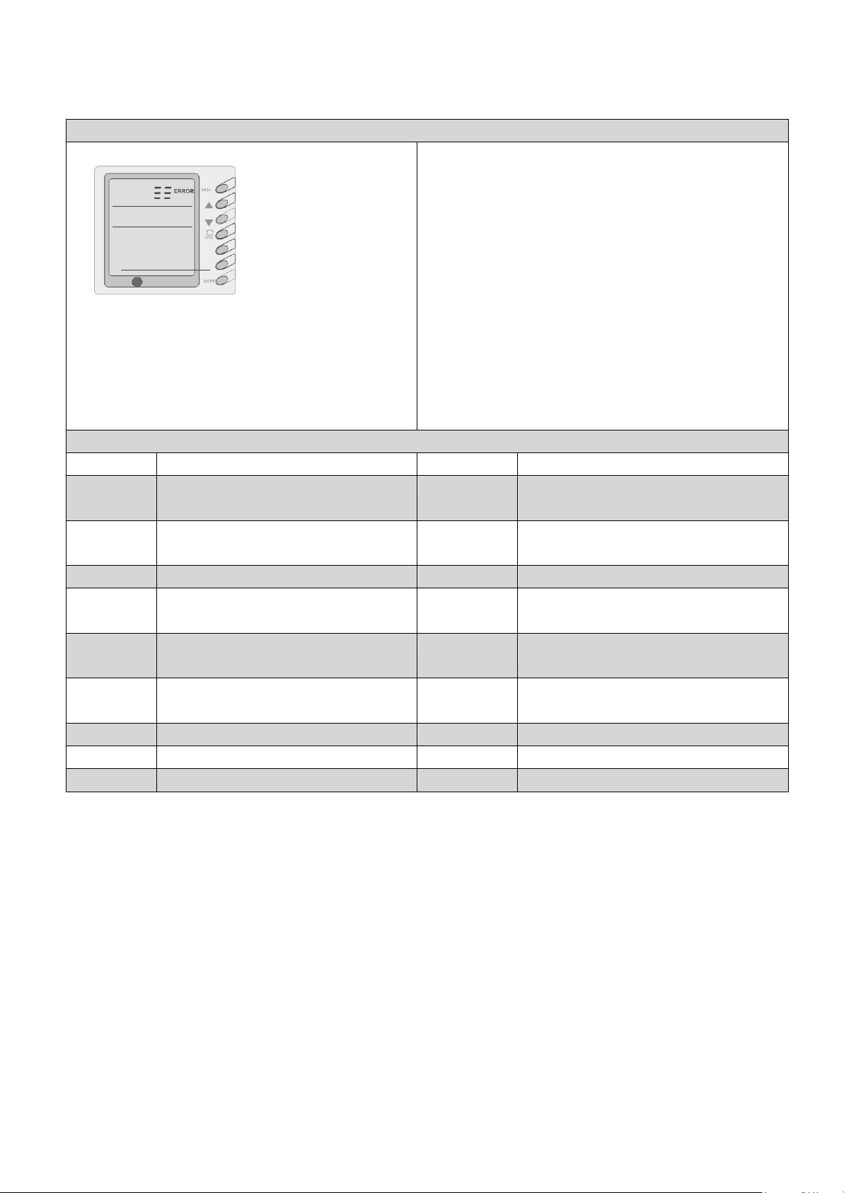
Failure Display
SLEEP
TIMER
When there is failure in the unit operation, “ERROR” will flash on
the LCD of the wire controller and the code of failure will also be
displayed. When there are multiple failures at the same time, the
codes of failures will be displayed one after one on the wire controller.
The first digit of the code denotes the system number. When there is
only one system, the system number is not displayed. The last two
digits denote the detailed failure code. For example, the code in left
means low pressure protection of compressor.
The Codes of Failure Definitions are as Follows:
Fault code
Fault
Fault code
Fault
E0
Pump Failure
F0
Failure of Indoor Room Sensor at Air
Intake
E1
Compressor High Pressure
Protection
F1
Failure of Evaporator Temp. Sensor
E2
Indoor Frost-Proof Protection
F2
Failure of Condenser Temp. Sensor
E3
Compressor Low Pressure
Protection
F3
Failure of Outdoor Ambient Sensor
E4
Compressor Exhaust High
Temperature Protection
F4
Failure of Exhaust Temp. Sensor
E5
Compressor Overheat
F5
Failure of Indoor Room Sensor at Wire
Controller
E6
Communications Failure
FF
All of the terminal air valve closed
E8
Indoor Fan Protection
E9
Full Water Protection
E5 Material Malfunction Will Be Showed By The Indicator Light On The Mother Board Of Outside Unit

Wire controller (with week timer functions)
Each part of wired controller
1
Timing Display
11
Timer interval Display
2
Ambient Temperature Display
12
Sleeping Status Display
3
Energy Saving Status Display
13
Mode Button
4
Set Temperature Display
14
Set Temperature Increase Button
5
Week Display
15
Set Temperature Decrease Button
6
Fan Speed Display (Auto, High Speed,
Medium Speed, Low Speed)
16
Fan Speed Button
7
Defrosting Status Display
17
Sleep Button
8
Fresh Air Status Display
18
Timing Button
9
Mode (Cooling, Dehumidifying, Fan,
Heating, Auto)
19
ON/OFF Button
10
Malfunction Display
WARNING!
●Never install the wired controller where there is water leakage.
●Never knock, throw or frequently open the wired controller.
Fig.1
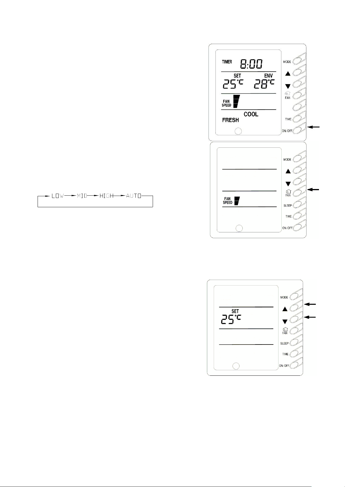
1) ON/OFF(Fig.2)
Press the “ON/OFF” button, the unit will start running.
Press the “ON/OFF” button again, the unit will stop
running.
2)Fan Control (Fig.3 is about display region and the
same as following figures.)
When press FAN button once, the fan speed will be changed
as follow:
In DRY mode: the fan speed will be set at low automatically.
3)Setting Temperature (Fig.4)
Press th e setting temperature button:
▲:For temperature increase
▼:For temperature decrease
(Press this button once, the temperature will be increased or
decreased by 1℃.)
Note: Press ▲+ ▼button for 5 seconds, “EE” will appear
Fig.2
Fig.3
where SET TEMP is displayed and all buttons are shielded.
Press ▲+▼button again for 5 seconds to cancel locked
function.
If long-distance monitoring controller or central controller
shield displayer, all buttons and signals from remote
controller will be shielded too, and CC will be displayed
where SET TEMP is displayed.
Setting temperature range under each mode:
Fig.4

HEAT --------
16℃~30℃
COOL
-------- 16℃~30℃
DRY -------- 16℃~30℃
FAN -------- can not be set
4)Sleep Function Setting(Fig.5)
If the unit has been running for 1 hour after pressing
SLEEP button in cooling or dry mode, set temp will
increase by 1℃, and then by 1℃ in another two hours,
then the unit runs at this temp.
If the unit has been running for 1 hour after pressing
SLEEP button in heating mode, set temp will
decrease by 1℃, and then by 1℃
in another two
hours, then the unit runs at this temp.
No this function in fan mode.
5)Running Mode Setting (Fig.6)
Every press of mode button, the operation mode will
Fig.5
change as follow:
→ COOL→ DRY → FAN → HEAT→ AUTO
In cool mode, COOL will light, in which case, setting
temperature should be set to be lower than present
ambient temperature; If not, the unit will not operate in cool
mode and only the fan is active.
In dry mode, DRY will light .Indoor fan will run at low
speed in certain temp. range. Dry efficiency as well as
energy saving efficiency in this mode is much better than
that in cool mode
In heat mode, HEAT will light. The setting temperature
should be set to be higher than present ambient
temperature; if not, the unit can not operate in heat mode.
In fan mode, FAN will light.
In auto mode, AUTO will light and the unit will run at the
Fig.6
mode automatically adjusted according to ambient
temp.
In heating mode, if outdoor temp is low with high
humidity, the outdoor unit will be frosted resulting in low

efficiency of heating, in which case, the controller will
automatically start to defrost with DEFROST displayed.
Note: No heating for cooling-only unit and auto
mode will be shielded after setting energy saving.
6) Setting Timer (Fig.7, 8, 9)
Timer function in this wired controller conneted with
weekly timer is invalid and wired controller will be
controlled by weekly timer.
Either in ON status or OFF status of the unit press TIMER
button into timing setting, and then press▲ or ▼
button to set timing(Fig.7),set time(Fig.8) and delete
timing (Fig.9). At last, press TIMER to set it.
Fig.7
Fig.8
Fig.9

In timing setting mode, press MODE button to select
any desired setting object: Week (1-7), timer
interval (1-4), timing (Timer on or Timer off time), min.
part or hour part of time, and then press▲ or
▼ button to adjust this object, which is fixed by pressing
TIMER button or can be canceled by pressing Timer
again. During fixing setting there must be blinking
characters. During canceling setting, if there are also
blinking characters, setting can be continuous till quit It by
pressing ON/OFF button; meanwhile, timing data are
memorized. (Fig.10, 11)
In time setting mode press MODE button to select any
desired setting object: Week (1-7), min. part (0-59)
or hour part (0-23), and then press▲ or ▼ button to
Fig.10
Fig.11
adjust this object, which is fixed by pressing TIMER
button or can be canceled by pressing Timer again.
During fixing setting there must be blinking
characters. During canceling setting, if there are also
blinking characters, setting can be continuous till quit
It by pressing ON/OFF button.(Fig.12)
Fig.12

In deleting timing status, press ▲ or ▼ button to
select one day of a week, and then press TIMER button
to confirm ,in which case, ”dd” is
displayed .The day also can be canceled by pressing
TIMER button without “dd” displayed. At last, press
ON/OFF button to quit the setting after finish.(Fig.13)
7)
Energy saving setting
(Fig.14)
Press FAN+▼ for 5 seconds into energy saving menu, in
Fig.13
which case, SAVE and COOL is displayed ( If it’s the first
time
for setting, initial value 26℃ will be displayed.) ,lower-
limit
temp is displayed where set temp is displayed and set temp
during setting is displayed and blinking. Press▲ and ▼ to
set
lower-limit cooling temp (setting range is16-30) and then
press ON/OFF to fix .Press ▲ and ▼ to set upperlimit cooling temp, which will be displayed where ambient
temp is displayed (setting range is 16-30), and then press
ON/OFF to fix.
Note: Upper- limit temp can not be set to be lower than lowerlimit temp, or else the higher temp will be defaulted to be
upper limit and the lower one to be lower- limit. Press MODE
Fig.14
button to set energy saving in cooling or dry mode and then
switch to energy saving setting in heating mode, in which case,
SAVE and HEAT will be displayed, which is quitted by

pressing FAN and ▼ for 5 seconds. If there is no operation
after the energy saving interface appears in 20s when the
system responds the last press of one button, the system will
trip off the menu and display normal interface of unit off.
SAVE will be displayed in LCD at next startup of the unit if
above setting has been finished. Either by pressing buttons of
the displayer or remote controller, the setting temp can never
be set to be higher than temp range set under energy saving
mode before. For example, lower-limit cooling temp under
energy saving mode is 23℃ and upper limit is 28℃,so the
user can only set cooling temperature in the range of 23-28℃.
If the same limit temperature is set, th e unit will only run under
corresponding mode at this setting temp. Press Fan+▼
simultaneously for 5s to quit this function if it has been
effective, but former setting value can not be cleared, which will
be as the original value of next setting. If the power is off,
energy saving setting will be memorized, which continues
effectively after the power is on next time. If energy-saving
mode and sleeping mode is setting, auto mode will be
shielded.
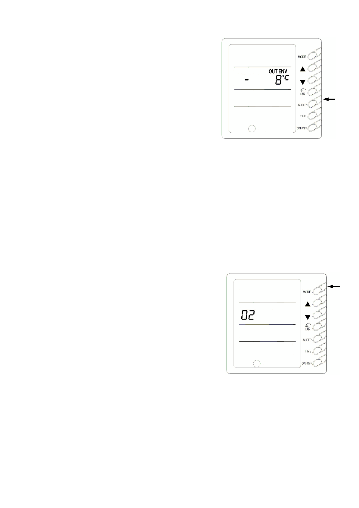
9)Outdoor ambient temp display ( Fig.15)
In normal condition, only indoor ambient temp is
displayed where “ENVIROMENT” is displayed. Either at
unit on or off press SWING button for 5 seconds, outdoor
ambient temp (OUT ENV) will be displayed.
① If outdoor temp is tested to be above zero, there will be
no display where setting temp is displayed and outdoor
ambient temp tested by inner system will be displayed
where ambient temp is displayed.
② If outdoor temp is tested to be below zero, “-” will be
displayed where set temp is displayed and absolute
value of outdoor ambient temp tested by inner system
will be displayed where ambient temp is displayed.
After 10- second display, the system will return to
display interface of indoor ambient temp.
Note: This unit function is invalid without connecting with
outdoor ambient temp sensor.
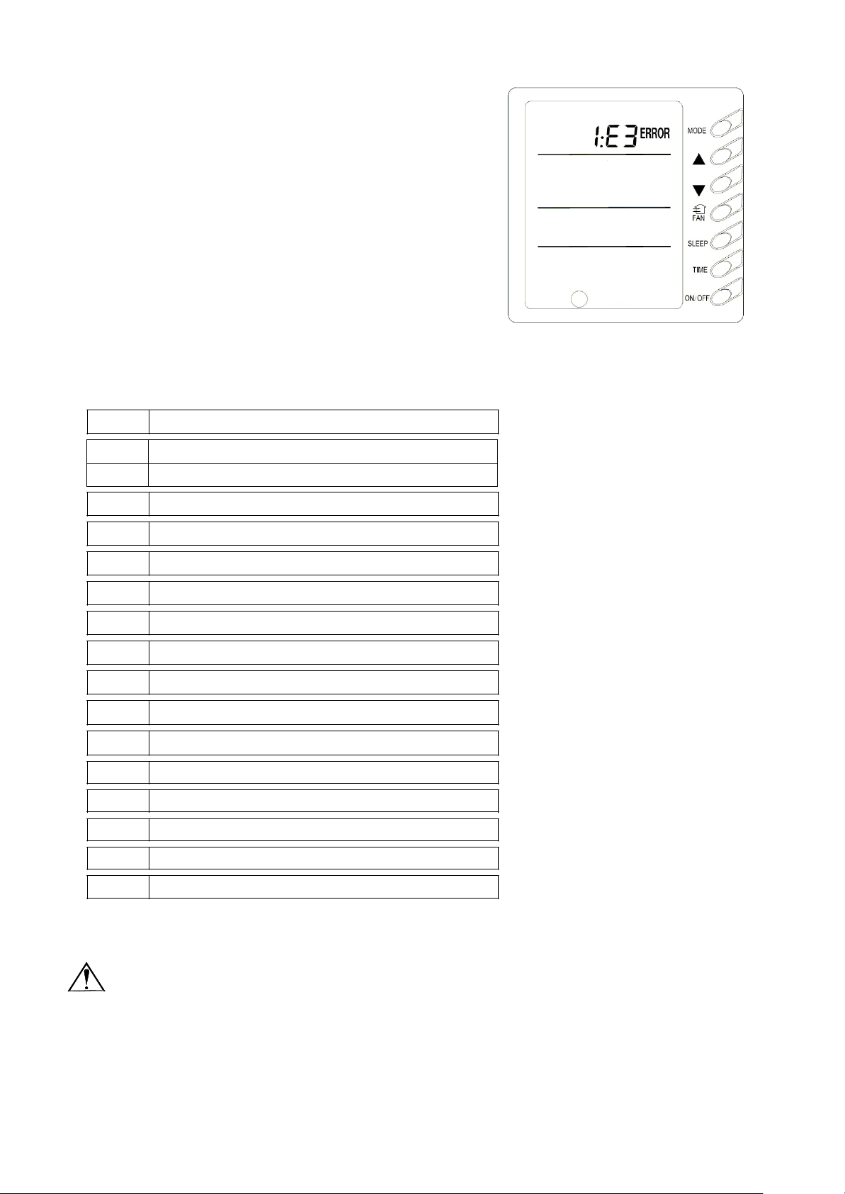
10) Power –off Memory setting (Fig.16)
Press MODE button continuously for 10s and select if
Fig.15
memorize start or stop status of the unit at unit off.01 where
set temp is displayed indicates memorizing start and stop
status of the unit after power off .02, which quit by pressing
ON/OFF button ,indicates not memorizing. If after the
interface of memorizing start and stop status of the unit
appears, there is no operation in 20s when the system
responds the last press of one button, the system will trip off
the menu and display normal interface of unit off, but it also
memorizes present information.
Fig. 16
E0
Water pump malfunction
E1
Compressor high-pressure protection
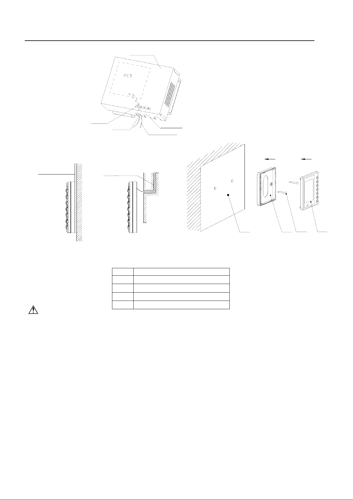
11) Malfunction Display (F ig.17)
If malfunction happens during operating of the unit, ERROR will
blink with error code displayed. If some malfunctions occur
simultaneously, the codes will be displayed in cycle. The first
number indicates system number, which won’t appear if only one
system. The last two numbers indicate detailed malfunction codes.
For example, the right figure indicates compressor low-pressure
protection of system 1.
Codes Malfunction
E2 Indoor anti-freezing protection
E3 Compressor low-pressure protection
E4 Compressor high-temp. exhaust protection
E5 Compressor overload protection
E6 Communication malfunction
E8 Indoor fan protection
E9 Water-full protection
F0 Air inlet indoor ambient temp. sensor malfunction
F1 Evaporator temp. sensor malfunction
F2 Condenser temp. sensor malfunction
F3 Outdoor ambient temp. sensor malfunction
F4 Exhaust ambient temp. sensor malfunction
F5 Ambient temp. sensor malfunction in displayer
EH Auxiliary electric heat malfunction
Fig.17
Note!
If EH malfunction happens, please power the unit off immediately and ask professionals for
help.

Instructions of Unit Installation
Installation of Connecting Pipe
Position and Method of Installing Wire Controller
1. One end of the control wire of the wire controller is connected with main board of electric box of
indoor unit inside, it should be tightened by wire clamp, the other end should be connected with the
wire controller (installation sketch map as shown in below). The control wire be used for the indoor
unit and wire controller, which is special, the length is 8 meters,
the material be adopted for the control wire should be metallic substance. The wire controller could not
be disassembled and the control wire be used for the wire controller should not
be changed by users optionally, the installation and maintenance should be carried out by the
professional personnel.
2. First select an installation position. According to the size of the control wire of the wire controller,
leave a recess or a embedded wire hole to bury the control wire.
3. If the control wire between the wire controller and the indoor unit is surface-mounted, use 1#
metallic pipe and make matching recess in the wall (refer to Figure 41); If concealed installation is
adopted, 1# metallic pipe can be used (Refer to Figure 42).
4. No matter if surface mounting or concealed mounting is selected, it is required to drill 2 holes (in the
same level) which distance shall be the same as the distance (60mm) of installation holes in the
bottom plate of the wire controller. Then insert a wood plug into each hole. Fix the bottom plate of the
wire controller to the wall by using the two holes. Plug the control wire onto the control panel.
Lastly install the panel of the wire controller.
Caution:
During the installation of the bottom plate of the wire controller, pay attention to the direction of
the bottom plate. The plate’s side with two notches must be at the lower position, and otherwise the panel
of the wire controller cannot be correctly installed.
Instructions of Unit Installation Installation of Wire Controller
No.
Name
1
Wall Surface
2
Bottom Plate of Wire Controller
3
Screw M4XIO
4
Panel of Wire Controller
Wire clamp
metallic pipe metallic pipe
Figure 43 Surface
Mounting of Cable
Control wire
Electric box cover
Cable-cross loop
Communication wire
Figure 44 Concealed
mounting of Cable
sketch map for indoor unit
communication wire
1
Figure 45 Schematic Diagram of Installation
2
3
4
Caution:
1.
The communication distance between the main board and the wire controller is 8 meters.
2.
The wire controller shall not be installed in a place where there is water drop or large amount
of water vapor.
Instructions of Unit Installation
Electrical Installation
Caution: Before installing the electrical equipment, please pay attention to the following matters
(1)
nameplate.
(2)
(3)
An electricity leakage protection switch and an air switch with gap between electrode heads larger
than
3mm shall be installed in the fixed line.
twisted wires.
the multiple twisted wires.
the
Power Cable Connection:
1. Air-conditioning unit with single-phase power supply
(1)
(2)
(3) Connect the power supply cable to the “L, N” terminals and the grounding screw on the metal
(4 ) Use cable fastener to bundle and fix the cable.
Check to see if the power supply used conforms to the rated power supply specified on the
The capacity of the power supply must be large enough.
The lines must be installed by professional personnel.
1. Connection of signal wire
(1) Use wire stripper to strip the insulation layer (25mm long) from the end of the signal wire.
(2) Remove the screw at the terminal board of the air-conditioning unit.
(3) Use pliers to bend the end of the signal wire so that a loop matching the screw size is formed.
(4) Put the screw through the loop of the signal wire and fix the loop at the terminal board.
2. Connection of multiple twisted wires
(1) Use wire stripper to strip the insulation layer (10mm long) from the end of the multiple
(2) Remove the screw at the terminal board of the air-conditioning unit.
(3) Use crimping pliers to connect a terminal (matching the size of the screw) at the end of
(4) Put the screw through the terminal of the multiple twisted wires and fix the terminal at
terminal board.
Warning:
If the power supply flexible line or the signal line of the equipment is damaged, only use special
flexible line to replace it.
1. Before connecting lines, read the voltages of the relevant parts on the nameplate. Then carry
out line connection according to the schematic diagram.
2. The air-conditioning unit shall have special power supply line which shall be equipped with
electricity leakage switch and air switch, so as to deal with overload conditions.
3. The air-conditioning unit must have grounding to avoid hazard owing to insulation failure.
4. All fitting lines must use crimp terminals or single wire. If multiple twisted wires are connected
to terminal board, arc may arise.
5. All line connections must conform to the schematic diagram of lines. Wrong connection may
cause abnormal operation or damage of the air-conditioning unit.
6. Do not let any cable contact the refrigerant pipe, the compressor and moving parts such as fan.
7. Do not change the internal line connections inside the air-conditioning unit. The manufacturer
shall not be liable for any loss or abnormal operation arising from wrong line connections.
Remove the front-side panel of the outdoor unit.
Pass the cable though rubber ring.
electric box.
which have been specially pointed out by our designers:
Troubleshooting and Maintenance
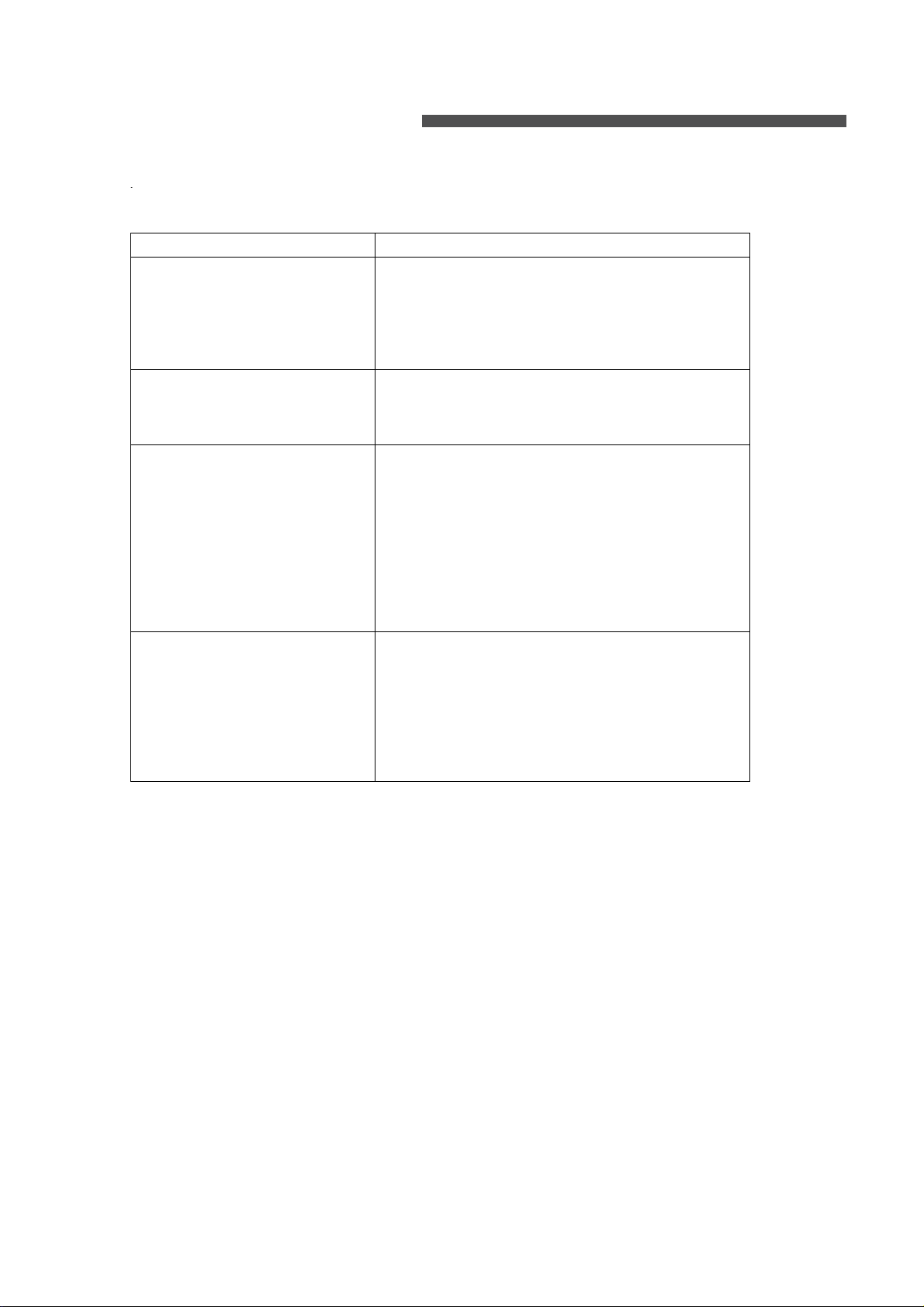
Failure
Possible Reasons
The unit cannot be started.
1. The power supply is not connected.
2. Electrical leakage of air-conditioning unit
causes tripping of leakage switch.
3. The operating keys are locked.
4.
The control loop has failure.
The unit operates for a while
and then stops.
1. There is obstacle in front of the condenser.
2. The control loop is abnormal.
3. Cooling operation is selected when the
outdoor ambient temperature is above 43 .
Poor cooling effect.
1. The air filter is dirty or blocked.
2. There is heat source or too many people
inside the room.
3. The door or window is open.
4. There is obstacle at the air intake or outlet.
5. The set temperature is too high thus cooling
is hindered.
6. There is refrigerant leakage.
7. The performance of room temperature
sensor becomes worse
Poor heating effect
1. The air filter is dirty or blocked.
2. The door or window is not firmly closed.
3. The set room temperature is too low thus
heating is hindered.
4. There is refrigerant leakage.
5. The outdoor ambient temperature is lower
than -5 .
6. Control line is abnormal.
If your air-conditioning unit suffers from abnormal operation or failure, please first check the
following points before repair:
WARNING!
● This appliance is not intended for use by persons (including children) with reduced physical sensory
or capabilities, or leak of experience and konwledge , unless they have been given supervision on
instruction concerning use of appliance by a person responsible for their safety.
● Children should be supervised to ensure that they do not play with the appliance.
This product must not be disposed together with the domestic
waste. This product has to be disposed at an authorized place
for recycling of electrical and electronic appliances.
66129904714
 Loading...