


MULTI
DUCTLESS INVERTER
HEAT PUMP
INSTALLATION
MANUAL
PANEL CONSOLE TYPE
INDOOR UNIT
Models:
GEN(12)AA-D3DNA1C/I
GEN(18)AA-D3DNA1C/I

Contents
The figures in this manual may be different with the material objects, please
refer to the material objects for reference.
This appliance is not intended for use by persons (including children) with
reduced physical , sensory or mental capabilities or lack of experience
and knowledge,unless they have been given supervision or instruction
concerning use of the appliance by a person responsible for their safety.
Children should be supervised to ensure that they do not play with the appliance.
Thank you for choosing a
C&H Multi Ductless Heat Pump!
You can feel confident in your selection because the same
pride incraftsmanship and engineering knowledge that goes
into millions of other C&H installed products worldwide has
gone into your unit.
Please read this owner’s manual carefully before
operationand retain it for future reference.
INSTALLATIONINSTRUCTIONS
1. Installation of indoor unit...........................................................................................1
2. Routine check after installation.................................................................................9
3. Configuration of connection pipe and additional volume of refrigerant......................10

INSTALLATION INSTRUCTIONS
The appliance shall not be installed in the laundry.
Installation of indoor unit
●
●
●
●
Such a place where cool air can be distributed
Such a place where condensation water is easily
Such a place that can handle the weight of indoor unit.
Such a place which has easy access for maintenance.
drained out.
throughout the room.
SELECTION OF INSTALLATION LOCATION.
Each type is similar to the other as follows;
●
●
THERE ARE 2 STYLES OF INSTALLATION.
CEILING TYPE
FLOOR TYPE
Schematic drawing of hooks:
Where there is too much of oil area.
Where it is acid base area.
Where there is irregular electrical supply.
●
●
●
TOOCCUR.
AIR CONDITIONER TROUBLEIS LIABLE
CAUTIONS FOR INSTALLATION WHERE
8in
(
200mm
)
Indoor unit
The indoor unit should be sited in a place where:
1) the restrictions on installation specified in the indoor
unit installation drawings are met.
2) both air intake and exhaust have clear paths met.
3) the unit is not in the path of direct sunlight.
4) the unit is away from the source of heat or steam.
5) there is no source of machine oil vapour (this may shorten indoor unit life).
6) cool(warm) air is circulated throughout the room.
7) the unit is away from electronic ignition type fluorwscent lamps
(inverter or rapid stert type) as they may shorten the remote
controller range.
8) the unit is at least 39in(1m) away from any television or
radio set(unit may cause interference with the picture or
sound).
Indoor Unit Installation Drawings
The indoor unit may be mounted in any of the three styles shown here.
Exposed
Floor lnstallation Wall Installation
Molding
Mounting plate
Half conceated
Concealed
Grid(field supply)
Location for securing the installation panel.
27in(
700
mm)
5in(
120
mm)
9in(
220
mm)
7in
(
170
mm)
1in(
30
mm)
25in(
644
mm)
120
mm
220
mm
6in
(
160
mm)
1in(
30
mm)
22in(
570
mm)
23in(
600
mm)
8in(
200
mm)
59in(150cm)
or more
59in(150cm)
6in(15cm) or
below from
the floor
59in(150cm)
or more
59in(150cm)
or more
or more
1
INSTALLATION
PAPER PLANK

3”
(75)
Refrigerant piping
1)Drill a hole ( 2 1/8”(55mm) in diameter ) in the spot indicated by the symbol in the illustration as
below .
2)The location of the hole is different depending on which side of the pipe is taken out .
3)For piping ,see Connecting the refrigerant pipe ,under Indoor Unit Installation(1).
4)Allow space around the pipe for a easier indoor unit pipe connection.
Min.allowable length
The suggested shortest pipe length is 98in(2.5m),in order to avoid noise from the outdoor unit and vibration.
(Mechanical noise and vibration may occur depending on how the unit is installed and the environment in which it is
used.)
See the installation manual for the outdoor unit for the maximum pipe length.
CAUTION
14in(350mm)
wall
Refrigerant pipe
1 3/4”
(45)
1 3/4”
(45)
1 3/4”
(45)
1 3/4”
(45)
1 3/4”
(45)
2 3/8”
(60)
3”
(75)
3”
(75)
3”
(75)
3”
(75)
1 3/4”
(45)
Left back piping
gnipipmottobthgiRgnipipmottobtfeL
Wall
Unit : in(mm)
Right back piping
Left/right piping
2
INSTALLATION INSTRUCTIONS
Installation of indoor unit
Floor

Drain piping
1)Use commercial regid polyvinyl chloride pipe general VP 20 pipe, outer diameter 1”(26mm), inner diameter
3/4”(20mm) for the drain pipe.
2)The drain hose (outer diameter 3/4”(18mm) at connecting end, 9”(220mm) long)is supplied with the indoor unit.
Prepare the drain pipe picture below position.
3)The drain pipe should be inclined downward so that water will flow smoothly without any accumulation.(Should not
be trap.)
4)Insert the drain hose to this depth so it won’t be pulled out of the drain pipe.
5)Insulate the indoor drain pipe with 3/8”(10mm) or more of insulation material to prevent condensation.
6)Remove the air filters and pour some water into the drain pan to check the water flows smoothly.
4”(100mm)
Drain hose
4”(100mm)
6”(150mm)
Vinyl chloride
drain pipe
2”(50mm)
or more
Reducer
Must be no trap
Do not touch water
3
INSTALLATION INSTRUCTIONS
Installation of indoor unit
Boring a wall hole and installing wall embedded pipe
For walls containing metal frame or metal board ,be sure to use a wall embedded
pipe and wall cover in the feed-through hole to prevent water leakage.
Be sure to caulk the gaps around the pipes with caulking material to prevent
water leakage.
1)Bore a feed-through hole of 2 1/8”(55mm) in the wall so it has a down slope
toward the outside.
2)Insert a wall pipe into the hole.
3)Insert a wall cover into wall pipe .
4)After completing refrigerant piping, wiring, and drain piping, caulk pipe hole gap
with putty.
Inside Outside
Caulking
Wall embedded pipe
(field supply)
Wall hole cover
Wall embedded pipe
(field supply)
Φ
2 1/8”
(
55
mm)

Open the front panel, remove the 4 screws and dis-
mount the front grille while pulling it forward.
Follow the procedure below when removing the slit
portions.
Front panel
Open the front panel
Remove
front grille
Casing
Front
grille
Remove 4 screws
3 tabs
For Moldings
Remove the pillars. (Remove the slit portions on the
bottom frame using nippers.)
For Side Piping
Remove the pillars.
1)Remove the 7screws.
2)Remove the upper casing (2 tabs).
3)Remove the left and right casings (2 tabs on each
side ).
4)Remove the slit portions on the bottom frame and
casings using nippers .
5)Return by following the steps in reverse order(3>2>
1).
3)Side
casings
2)Upper casing
3)Side
casings
Remove the pillar
Remove 7 screws
Casing
Remove the pillar
Casing
Remove the pillar
Bottom frame
Secure using 6 screws for floor installations.(Do not forget to secure to the rear wall.)
For wall installations, secure the mounting plate using 5 screws and the indoor unit using 4 screws.
Follow the arrows to disengage the clasps on the
front case to remove it.
Installing indoor unit
1.Preparation
2.Installation
4
INSTALLATION INSTRUCTIONS
Installation of indoor unit

The mounting plate should be installed on a wall which can support the weight of the indoor unit.
1) Temporarily secure the mounting plate to the wall, make sure that the panel is completely level, and mark the boring
points on the wall.
2) Secure the mounting plate to the wall with screws.
6screws
Casing
Floor Installation
Wall Installation
6screws
Molding
3) Once refrigerant piping and drain piping connections are complete, fill in the gap of the through hole with putty. A gap
can lead to condensation on the refrigerant pipe, and drain pipe, and the entry of insects into the pipes.
4) Attach the front panel and front grille in their original positions once all connections are complete.
Flaring the pipe end
1)Cut the pipe end with a pipe cutter.
2)Remove burrs with the cut surface facing downward so that the chips do not enter the pipe.
3)Fit the flare nut on the pipe.
4)Flare the pipe.
5)Check that the flaring is properly made.
WARNING
1) DO not use mineral oil on flared part.
2) Prevent mineral oil from getting into the system as this would reduce the lifetime of the units.
3) Never use piping which had been used for previous installations. Only use parts which are delivered with the unit.
4) Do never install a drier to this R410A unit in order to guarantee its lifetime.
5) The drying material may dissolve and damage the system.
6) Incomplete flaring may cause refrigerant gas leakage.
Make sure that the
flare nut is fitted
The pipe end must
be evenly flared in
a perfect circle
Flare’s inner
surface must
be scratch-free
Cut exactly
at right
angles
Renove
burrs
Flaring
Set exactly at the position shown below
A
Die
A
0-0.5mm
1.0-1.5mm
1.5-2.0mm
Flare tool for R410A
Clutch-type
Clutch-type
(Rigid-type)
Wing-nut type
(lmperial-type)
Conventional flare tool
8in (
200
mm
)
5
INSTALLATION INSTRUCTIONS
Installation of indoor unit

Connecting the refrigerant pipe
Wrench
Indoor unit tubing
Open-end wrench (fixed)
Connection pipe
Flare nut
1)Use torque wrenches when tightening the flare nuts to prevent damage to the flare nuts and gas leaks.
Coat here with refrigeration oil
2)Align the centres of both flares and tighten the flares and tighten the flare nuts 3 or 4 turns by hand.
Then tighten them fully with the torque wrenches.
3)To prevent gas leakage, apply refrigeration oil on both inner and outer surfaces in the flare. (Use refrigeration oil for
R410A.)
Liquid side
09K/12K
09K/12K
18K
09K 18K
09K/12K/18K18K
3/8 inch 1/2 inch 1/4 inch
31-35
N.m
50-55
N.m 15-20
N.m
Flare nut tightening torque
Gas side
Caution on piping handling
1)Protect the open end of the pipe against dust and moisture.
2)All pipe bends should be as gentle as possible. Use a pipe bender for
bending.
(Bending radius should be 1 1/6in to 1 3/5in (30 to 40mm) or larger.)
Gas pipe
Gas pipe
insulstion
Finising tape
Inter-unit wiring
Liquid pipe
Liquid pipe
insulation
Selection of copper and heat insulation materials
When using commercial copper pipes and fittings, observe the
following:
1)Insulation material: Polyethylene foam
Heat transfer rate:0.041 to 0.052W/mK(0.035 to 0.045kca/(mh
°C)
Refrigerant gas pipe’s surface temperature reaches 230
°F
(110
°C)
max.
Choose heat insulation materials that will withstand this temperature.
2)Be sure to insulate both the gas and liquid piping and to provide insulation dimensions as below.
Liquid side
Liquid pipe
thermal insulation
O.D.
3/8”
O.D. 1
/2”
O.D.
1/4”
I.D. 1
/2”-3/5”
I.D.
9/16”-5/8”
I.D.
5/16”-3/8”
noitalusnilamrehtepipsaGedissaG
0.38in (10mm) Min.
ssenkcihT
0,03in (0.8mm)
ssenkcihT
3)Use separate thermal insulation pipes for gas and liquid refrigerant pipes.
Be sure to
place a cap.
If no flare cap is
available,cover
the flare mouth
with tape to keep
dirt or water out.
INSTALLATION INSTRUCTIONS
Installation of indoor unit
6

7
Checking for gas leakage
1)Check for leakage of gas after air purging
2)See the sections on air purges and gas leak checks in
the installation manual for the outdoor unit.
Attaching the connection pipe
Check for leakage here
Apply soapy water and check carefully for leaking gas.
wipe soapy water off after
the check is complete.
Attach the pipe after checking for gas leakage, described above.
1)Cut the insulated portion of the on-site piping, matching it up with the connecting portion.
2)Secure the slit on the refrigerant piping side with the butt joint on the auxiliary piping using the tape, making sure there
are no gaps.
3)Wrap the slit and butt joint with the included insulation sheet, making sure there are no gaps.
Refrigerant
pipe
Refrigerant
pipe
Refrigerant
pipe
Slit
Slit
Tape
Auxiliary pipe
Insulation sheet
CAUTION
1)Insulate the joint of the pipes securely.
Incomplete insulation may lead to water leakage.
2)Push the pipe inside so it does not place undue force on the front grille.
Connecting the drain hose
Insert the supplied C drain hose into the socket
of the drain pan.
Fully insert the drain hose until it adheres to a
seat of the socket.
Drain pan
Seal
Drain pan
Seal
Drain hose
INSTALLATION INSTRUCTIONS
Installation of indoor unit

Live the sensor securing plate, remove the front metal plate cover, and connect the branch wiring to the terminal block.
1)Strip wire ends 3/5”(15mm)
2)Mach wire colours with terminal numbers on indoor and outdoor unit’s terminal blocks and firmly screw wires to
the corresponding terminals.
3)Connect the earth wires to the corresponding terminals.
4)Pull wires to make sure that they are securely latches up, then retain wires with wire retainer.
CAUTION
1)Do not use tapped wires, stranded wires, extensioncords, or starburst connections, as they may cause overheating,
electrical shock, or fire.
2)Do not use locally purchased electrical parts inside the product. (Do not branch the power for the drain pump, etc, from
the terminal block.) Doing so may cause electric shock or fire.)
8
INSTALLATION INSTRUCTIONS
Installation of indoor unit
Outdoor unit
Indoor unit
Firmly fix the wires with the
terminal screws
Firmly fix the wires with the
terminal screws
When wire length exceeds 10m,
use 2.0mmdiameter wires
2 3
Terminal block
Electrical
component
box
Wire retainer
Use the specified wire type.
Shape wires so
that the front metal
plate cover will fit
securely.
Firmly secure wire
retainer so that
wires sustain no
external stress.
Front metal
plate cover
Sensor securing plate
N(1
)

Routine check after installation
INSTALLATION INSTRUCTIONS
9
Check after installation
Items to be checked Possible malfunction Situation
Has it been fixed firmly?
Have you done the refrigerant leakage test?
Is heat insulation sufficient?
Does the unit drain well?
Is the voltage in accordance with the rated
voltage marked on the nameplate?
Is the electrical wiring and piping connection
installed correctly and securely?
Has the unit been connected to a secure earth
connection?
Is the power cord specified?
Has the inlet and outlet been covered?
Has the length of connection pipes and the
refrigerant charge been record?
The unit may drop,shake or emit noise.
It may cause insufficient refrigerating capacity.
It may cause condensation and dripping.
It may cause condensation and dripping.
It may cause electric malfunction or damage the
part.
It may cause electric malfunction or damage the
part.
It may cause electrical leakage.
It may cause electric malfunction or damage the
part.
It may cause insufficient refrigerating capacity.
The refrigerating capacity is not accurate

INSTALLATION INSTRUCTIONS
10
Configuration of connection pipe and additional volume of refrigerant
1. Standard length of connection pipe
16ft(5m)、24ft(7.5m)、26ft(8m)
2. Min length of connection pipe
For the unit with standard connection pipe of 16ft(5m), there is no
limitation
for the min length of connection pipe. For the unit with standard
connection
pipe of 24ft(7.5m) and 26ft(8m), the min length of connection
pipe is 9ft(3m).
3. Max length of connection pipe
4. The calculation method of additional refrigerant oil and refrigerant charging
amount after prolonging connection pipe
After the length of connection pipe is prolonged for 32ft(10m) at the basis
of standard length, you should add 5ml of refrigerant oil for each
additional 16ft(5m) of connection pipe.
The calculation method of additional refrigerant charging amount (on the
(1) Additional refrigerant charging amount= prolonged length of liquid pipe × additional
refrigerant charging amount per meter
(2) When the length of connection pipe is above
16ft(5m)
, add refrigerant
according
to the prolonged length of liquid pipe. The additional refrigerant
charging
amount per meter is different according to the diameter of liquid pipe. See
Sheet 2.
basis of liquid pipe):
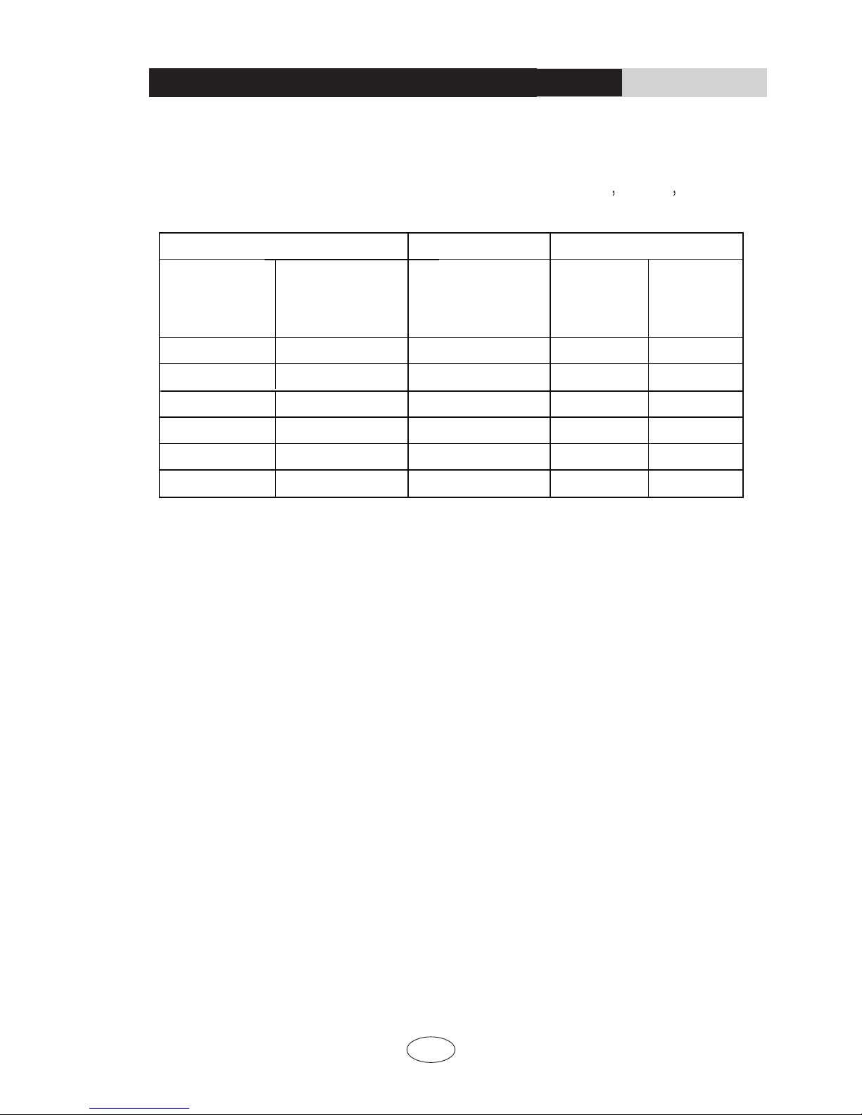
Sheet 1 Max length of connection pipe Unit: ft(m)
Capacity
Max length of
connection pipe
Capacity
Max length of
connection pipe
5000 Btu/h
(1465 W)
49(15)
24000 Btu/h
(7032 W)
7000 Btu/h
(2051 W)
49(15)
28000 Btu/h
(8204 W)
9000 Btu/h
(2637 W)
36000 Btu/h
(10548 W)
12000 Btu/h
(3516 W)
42000 Btu/h
(12306 W)
18000 Btu/h
(5274 W)
48000 Btu/h
(14064 W)
49(15)
65(20)
82(25)
82(25)
98(30)
98(30)
98(30)
98(30)
INSTALLATION INSTRUCTIONS
11
Configuration of connection pipe and additional volume of refrigerant
Sheet 2. Additional refrigerant charging amount
for R22 R407C R410A
and R134a
Note: The additional refrigerant charging amount in Sheet 2 is recommended
value, not compulsory.
Diameter of connection pipe in(mm) Indoor unit throttle Outdoor unit throttle
Liquid pipe Gas pipe Cooling only,
cooling and heating
(g / m)
Cooling only
(g / m)
Cooling and
heating
(g / m)
Ф3/8”(9.5) or Ф1/2”(12)
20 15 20
Ф1/4”(6) or Ф3/8”(9)
50 15 50
Ф1/2”(12) Ф3/4”(19)
30 120
Ф5/8”(16)
60 120
Ф3/4”(19)
-
250 250 250
Ф3/4”(22.2)
350 350 350
Ф5/8”(16) or Ф3/4”(19)
100
Ф1/4”(6)
Ф1”(25.4) or
Ф1 1/6”(31.8)
170
-

66162665
Add: West Jinji Rd, Qianshan, Zhuhai, Guangdong, China, 519070
MANUFACTURER: GREE ELECTRIC APPLIANCES, INC. OF ZHUHAI
www.cooperandhunter.us
 Loading...