

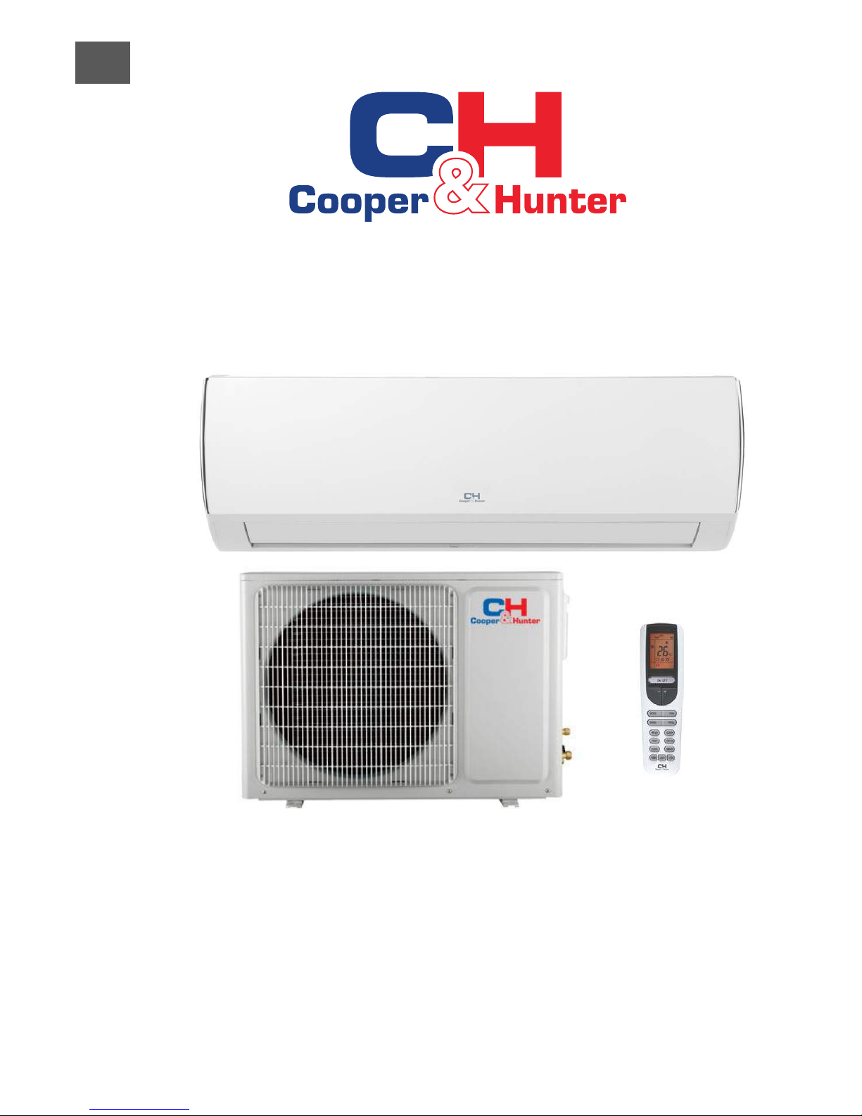
Split Air Conditioner
VERITAS INVERTER Series
M
ODEL
:
SERVICE MANUAL
Designed by Cooper&Hunter International Corporation, Oregon, USA
www.cooperandhunter.com
For proper operation, please read and keep this manual carefully.
CH-S12FT
XQ (WI-FI)
CH-S18FT
XQ (WI-FI)
EN

1. Summary
Part
Ⅰ
: Technical Information
Indoor Unit
Outdoor Unit
Remote Controller

Model
CH-S12FTXQ (Wi-Fi)
Product Code
CB470001101
Power
Supply
Rated Voltage V~ 220-240
Rated Frequency Hz 50
Phases 1
Power Supply Mode Outdoor
Cooling Capacity(Min~Max) W 3500
Heating Capacity(Min~Max) W 3600
Cooling Power Input(Min~Max) W 972
Heating Power Input(Min~Max) W 942
Cooling Current Input A 4.50
Heating Current Input A 4.4
Rated Input W 1500
Rated Cooling Current A 7.2
Rated Heating Current A 7.7
Air Flow Volume(SH/H/M/L/SL) m3/h 560/480/410/290/
-
Dehumidifying Volume L/h 1.4
EER W/W 3.60
COP W/W 3.82
SEER 6.1
SCOP(Average) 4.6
SCOP(Warmer) 5.1
SCOP(Colder) 3.3
Application Area m
2
15-22
Indoor
Unit
Indoor Unit Model
CH-S12FTXQ (Wi-Fi)
Indoor Unit Product Code
CB470N01100
Fan Type Cross-ow
Fan Diameter Length(DXL) mm Ф98X580
Cooling Speed(SH/H/M/L/SL) r/min 1350/1200/1050/750/-
Heating Speed(SH/H/M/L/SL) r/min 1350/1200/1050/850/-
Fan Motor Power Output W 20
Fan Motor RLA A 0.215
Fan Motor Capacitor μF 1
Evaporator Form Aluminum Fin-copper Tube
Evaporator Pipe Diameter mm Ф5
Evaporator Row-n Gap mm 2-1.4
Evaporator Coil Length(LXDXW) mm 584X22.8X266.7
Swing Motor Model MP24AA
Swing Motor Power Output W 1.5
Fuse Current A 3.15
Sound Pressure Level(SH/H/M/L/SL) dB (A) 40/37/28/24/-
Sound Power Level(SH/H/M/L/SL) dB (A) 55/47/44/38/-
Dimension(WXHXD) mm 790X275X200
Dimension of Carton Box(LXWXH) mm 850X339X262
Dimension of Package(LXWXH) mm 852X355X273
Net Weight kg 9
Gross Weight kg 11
2. Specications
2.1 Specication Sheet

Outdoor
Unit
Model of Outdoor Unit CH-S12FTXQ (Wi-Fi)
Product Code of Outdoor Unit CB427W04701
Compressor Manufacturer/Trademark Zhuhai Landa Compressor Co.; Ltd.
Compressor Model QXA-B102zE190
Compressor Oil RB68EP
Compressor Type Rotary
L.R.A. A 35.00
Compressor RLA A 4.80
Compressor Power Input W 1020
Overload Protector /
Throttling Method Capillary
Operation temp
o
C 16~30
Ambient temp (cooling)
o
C -24~48
Ambient temp (heating)
o
C -15~24
Condenser Form Aluminum Fin-copper Tube
Pipe Diameter mm Ф7.94
Rows-n Gap mm 1-1.4
Coil Length (LXDXW) mm 731X19.05X550
Fan Motor Speed rpm 900
Output of Fan Motor W 30
Fan Motor RLA A 0.4
Fan Motor Capacitor μF /
Air Flow Volume of Outdoor Unit m3/h 2200
Fan Type Axial-ow
Fan Diameter mm Ф438
Defrosting Method Automatic Defrosting
Climate Type T1
Isolation I
Moisture Protection IPX4
Permissible Excessive Operating
Pressure for the Discharge Side
MPa 4.3
Permissible Excessive Operating
Pressure for the Suction Side
MPa 2.5
Sound Pressure Level (H/M/L) dB (A) 51/-/-
Sound Power Level (H/M/L) dB (A) 62/-/-
Dimension (WXHXD) mm 848X596X320
Dimension of Carton Box (LXWXH) mm 878X360X630
Dimension of Package (LXWXH) mm 881X363X645
Net Weight kg 29.5
Gross Weight kg 32.5
Refrigerant R410A
Refrigerant Charge kg 0.90
Connection
Pipe
Length m 5
Gas Additional Charge g/m 20
Outer Diameter Liquid Pipe mm Ф6
Outer Diameter Gas Pipe mm Ф9.52
Max Distance Height m 10
Max Distance Length m 20
Note: The connection pipe applies metric diameter.
The above data is subject to change without notice; please refer to the nameplate of the unit.
Model
CH-S18FTXQ (Wi-Fi)
Product Code
CB460003800
Power
Supply
Rated Voltage V~ 220-240
Rated Frequency Hz 50
Phases 1
Power Supply Mode Outdoor
Cooling Capacity(Min~Max) W 5000
Heating Capacity(Min~Max) W 5300
Cooling Power Input(Min~Max) W 1430
Heating Power Input(Min~Max) W 1380
Cooling Current Input A 6.34
Heating Current Input A 6.12
Rated Input W 1860
Rated Cooling Current A 8.25
Rated Heating Current A 7.45
Air Flow Volume(SH/H/M/L/SL) m3/h 850/720/610/520/
-
Dehumidifying Volume L/h 1.8
EER W/W 3.50
COP W/W 3.84
SEER 6.1
SCOP(Average) 4.6
SCOP(Warmer) 5.1
SCOP(Colder) 3.3
Application Area m
2
21-31
Indoor
Unit
Indoor Unit Model
CH-S18FTXQ (Wi-Fi)
Indoor Unit Product Code
CB470N00800
Fan Type Cross-ow
Fan Diameter Length(DXL) mm Ф106X706
Cooling Speed(SH/H/M/L/SL) r/min 1230/1130/1030/800/-
Heating Speed(SH/H/M/L/SL) r/min 1350/1200/1050/900/-
Fan Motor Power Output W /
Fan Motor RLA A 0.35
Fan Motor Capacitor μF 2.5
Evaporator Form Aluminum Fin-copper Tube
Evaporator Pipe Diameter mm Ф7
Evaporator Row-n Gap mm 2-1.4
Evaporator Coil Length(LXDXW) mm 715X25.4X304.8
Swing Motor Model MP35CJ
Swing Motor Power Output W 2.5
Fuse Current A 3.15
Sound Pressure Level(SH/H/M/L/SL) dB (A) 44/39/33/28/-
Sound Power Level(SH/H/M/L/SL) dB (A) 58/53/50/45/-
Dimension(WXHXD) mm 970X300X224
Dimension of Carton Box(LXWXH) mm 1038X380X305
Dimension of Package(LXWXH) mm 1041X383X320
Net Weight kg 13.5
Gross Weight kg 16.5
Outdoor
Unit
Model of Outdoor Unit CH-S18FTXQ (Wi-Fi)
Product Code of Outdoor Unit CB427W06400
Compressor Manufacturer/Trademark Zhuhai Landa Compressor Co.; Ltd.
Compressor Model QXA-B102zE190A
Compressor Oil FVC68D or RB68EP
Compressor Type Rotary
L.R.A. A 35.00
Compressor RLA A 4.80
Compressor Power Input W 1020
Overload Protector /
Throttling Method Capillary
Operation temp
o
C 16~30
Ambient temp (cooling)
o
C -24~48
Ambient temp (heating)
o
C -15~24
Condenser Form Aluminum Fin-copper Tube
Pipe Diameter mm Ф7
Rows-n Gap mm 1-1.4
Coil Length (LXDXW) mm 742X38.1X550
Fan Motor Speed rpm 900
Output of Fan Motor W 30
Fan Motor RLA A 0.4
Fan Motor Capacitor μF /
Air Flow Volume of Outdoor Unit m3/h 2200
Fan Type Axial-ow
Fan Diameter mm Ф438
Defrosting Method Automatic Defrosting
Climate Type T1
Isolation I
Moisture Protection IPX4
Permissible Excessive Operating
Pressure for the Discharge Side
MPa 4.3
Permissible Excessive Operating
Pressure for the Suction Side
MPa 2.5
Sound Pressure Level (H/M/L) dB (A) 54/-/-
Sound Power Level (H/M/L) dB (A) 63/-/-
Dimension (WXHXD) mm 848X596X320
Dimension of Carton Box (LXWXH) mm 878X360X630
Dimension of Package (LXWXH) mm 881X363X645
Net Weight kg 33
Gross Weight kg 36
Refrigerant R410A
Refrigerant Charge kg 1.1
Connection
Pipe
Length m 5
Gas Additional Charge g/m 20
Outer Diameter Liquid Pipe mm Ф6
Outer Diameter Gas Pipe mm Ф9.52
Max Distance Height m 10
Max Distance Length m 20
Note: The connection pipe applies metric diameter.
The above data is subject to change without notice; please refer to the nameplate of the unit.
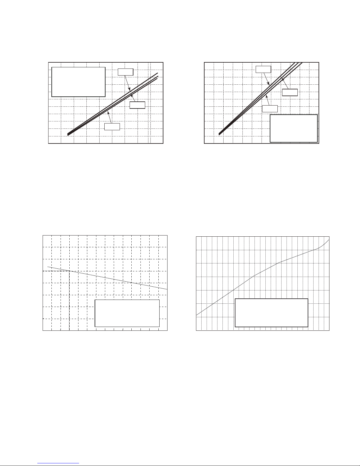
2.2 Operation Characteristic Curve
2.3 Capacity Variation Ratio According to Temperature
0 10 20 30 40 50 60 70 90 0 10 20 30 40 50 60 70 80 90 100 120 110
80
11
10
9
8
7
6
5
4
3
2
1
0
Compressor speed (rps)
) A ( t n e r r u C
11
10
9
8
7
6
5
4
3
2
1
0
Compressor speed (rps)
) A ( t n e r r u C
220V
230V
240V
220V
230V
240V
0 10 20 30 40 50 60 70 90 0 10 20 30 40 50 60 70 80 90 100
120
110
80
11
10
9
8
7
6
5
4
3
2
1
0
Compressor speed (rps)
)A(tnerruC
11
10
9
8
7
6
5
4
3
2
1
0
Compressor speed (rps)
)A(tnerruC
220V
230V
240V
220V
230V
240V
Conditions
Indoor: DB27°C/WB19°C
Outdoor: DB35°C/WB24°C
Indoor air flow: High
Pipe length: 5m
Conditions
Indoor: DB27°C/WB19°C
Outdoor: DB35°C/WB24°C
Indoor air flow: High
Pipe length: 5m
Conditions
Indoor: DB20°C/WB15°C
Outdoor: DB7°C/WB6°C
Indoor air flow: High
Pipe length: 5m
Conditions
Indoor: DB20°C/WB15°C
Outdoor: DB7°C/WB6°C
Indoor air flow: High
Pipe length: 5m
Cooling Heating
Cooling Heating
50
60
70
80
90
100
110
120
130
32 33 34 35 36 37 38 39 40 41 42 43 44 45 46
Capacity ratio(%)
Outdoor temp. (°C)
Capacity ratio(
%)
–15 –10 –5
110
100
90
80
70
60
50
40
0 5
7 10
Conditions
Indoor:DB20°C
Indoor air flow:Super High
Pipe length:5m
Outdoor temp.(°C)
Condition
Indoor:DB27°C WB19°C
Indoor air flow:
High
Pipe length:5m
Heating operation ambient temperature range is -15ºC~24ºC

32 33 34 35 36 37 38 39 43
40 41 42
100
105
95
90
85
80
75
70
65
60
55
50
Conditions
Indoor:DB27°C/WB19°C
Indoor air flow:Super High
Pipe length: 5m
Outdoor temp.(°C)
Capacity ratio (%)
Outdoor temp.(oC)
30
40
50
60
70
80
90
100
110
120
-22 -15 -10 -5 0 7 15 2
0 2
4
Conditions
Indoor:DB20°C/WB15°C
Indoor air flow:Super High
Pipe length: 5m
Cooling
Heating
Heating operation ambient temperature range is -22ºC~24ºC
2.4 Cooling and Heating Data Sheet in Rated Frequency
Rated cooling
condition(
o
C)
(DB/WB)
Model
Pressure of gas pipe
connecting indoor and
outdoor unit
Inlet and outlet pipe
temperature of heat
exchanger
Fan speed of
indoor unit
Fan speed of
outdoor unit
Compressor
frequency
(Hz)
Indoor Outdoor P (MPa) T1 (oC) T2 (oC)
27/19 35/24
12K 0.8 ~ 1.1 11 to 14 38 to 41
Super High High
72
18K 0.8 ~ 1.0 12 to 14 80 to 40 52
Rated heating
condition(
o
C)
(DB/WB)
Model
Pressure of gas pipe
connecting indoor and
outdoor unit
Inlet and outlet pipe
temperature of heat
exchanger
Fan speed of
indoor unit
Fan speed of
outdoor unit
Compressor
frequency
(Hz)
Indoor Outdoor P (MPa) T1 (oC) T2 (oC)
20/15 7/6
12K 2.8 ~ 3.2 38 to 41 2 to 5
Super High High
77
18K 2.2 ~ 2.4 70 to 40 1 to 5 65
Instruction:
T1: Inlet and outlet pipe temperature of evaporator
T2: Inlet and outlet pipe temperature of condenser
P: Pressure at the side of big valve
Connection pipe length: 5 m.
Cooling:
Heating:

2.5 Noise Curve
Indoor side noise
60
50
40
30
20
10
0
Indoor Fan Motor Rotating Speed
Noice/dB(A)
low
Middle
High Super High
Outdoor side noise
Compressor frequency/Hz
Noise/dB(A)
70
60
50
40
30
0
20 40 60 8
0 100
20
18K12K
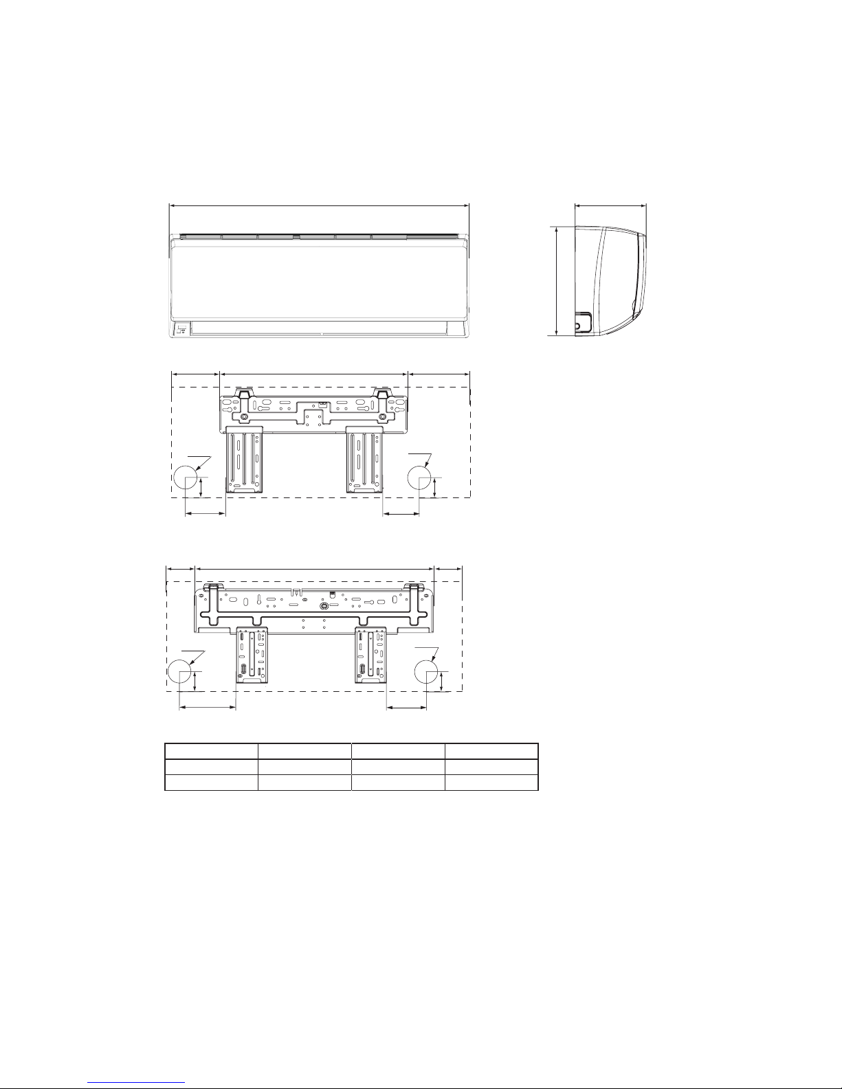
3. Outline Dimension Diagram
3.1 Indoor Unit
Unit:mm
104 685 181
140
190
38
Φ55
Φ55
38
90
150
54
168.5 462 159.5
Φ55
Φ55
54
W
D
H
12K
18K
Models W H D
12K 790 275 200
18K 970 300 224

3.2 Outdoor Unit
Unit:m
m
540
297
848
257
320
596
763
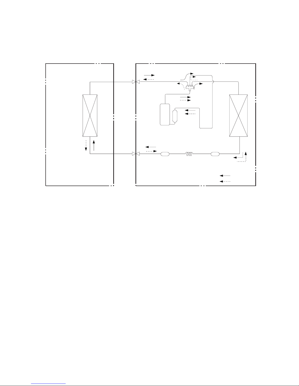
Indoor unit
Outdoor unit
COOLING
HEATING
4-Way valve
Discharge
Suction
Heat
exchanger
(evaporator)
Heat
exchanger
(condenser)
Valve
Valve
Liquid pipe
side
Gas pipe
side
Strainer Capillary Strainer
Accumlator
Compressor
4. Refrigerant System Diagram
Connection pipe specication:
Liquid pipe:1/4" (6mm)
Gas pipe:3/8" (9.52mm)
Cooling and heating model

5. Electrical Part
5.1 Wiring Diagram
● Indoor Unit
●Instruction
Symbol Symbol Color Symbol Symbol Color Symbol Name
WH White GN Green CAP Jumper cap
YE Yellow BN Brown COMP Compressor
RD Red BU Blue Grounding wire
YEGN Yellow/Green BK Black / /
VT Violet OG Orange / /
Note: Jumper cap is used to determine fan speed and the swing angle of horizontal lover for this model.
76(1625
7(03
6(1625
7(03
6(1625
57
5220
78%(
67(33,1*
',63/$<
35,17('&,5&8,7%2$5'
5(&(,9(5$1'
',63/$<%2$5'
&$%/(
&211(&7,1*
6:,1*8'
02725
%/2&.
7(50,1$/
$3
-803
&$3
%8
%.
<(*1
(9$325$725
3(
;7
1
0
287'22581,7
$3
3*
*(1(5$725
&2/'3/$60$
)$102725
0
5' %8
+($/7+1
+($/7+/
3*)
',63 ',63
%1
<(*1
57
1
&20287
/
%8
%.
%1
/
/
:,),02'8/(
$3
&200$18$/
:,),
6363222005
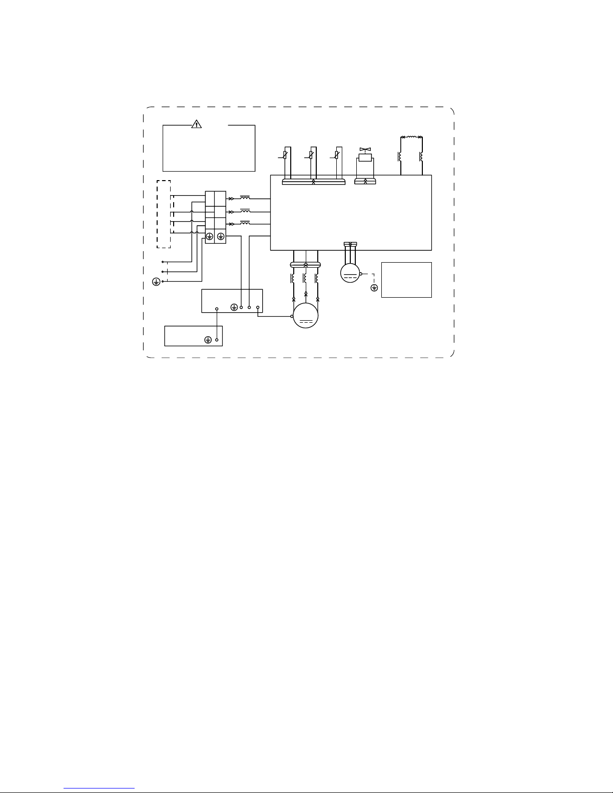
● Outdoor Unit
12K
18K
63610000453
%1
%.
%8
/
/
/
/
/
5,1*
0$*1(7,&
3(
/
%8
9
5'
<(
/;
/;
7(50,1$/
1
/
1
/
1
&1
2)$1
:
9
8
$30DLQ%RDUG
1
$&/
&208
3(
/
/
5($&725
/
%8
%1
7(03
6(1625
7(03
6(1625
7(03
57
57
57
6(1625
<9
:$<
:$<
0$*1(7,&
5,1*
N
N
N
0$*1(7,&
5,1*
;
0,',62/$7,21
6+((7
<(*1
3(
3(
<(*1
<(*1
<(*1
<(*1*1
9$/9(
28778%(
2875220
(;+$867
%/2&.
%8
%.
%1
%8:+
%1
%.
97
97
WKHULVNRIHOHFWULFVKRFN
3OHDVHGRQWWRXFKDQ\
WHUPLQDOZKHQWKHPDFKLQH
LVUXQQLQJVWRSSLQJRUKDV
EHHQSRZHUHGRIIIRUOHVV
WKDQPLQXWHVWRSUHYHQW
:$51,1*
%8
<(
5'
<(*1
,1'22581,7
:
8
&203
&203
;7
32:(5
)$1
0
3(
3(
127(
0RWRU
DSSOLHVWRWKH
LURQVKHOOPRWRU
JURXQG
(/(&75,&$/
%2;
<(*1
02725
RQO\

5.2 PCB Printed Diagram
Indoor Unit
● Top view
● Bottom view
1 Neutral wire terminal
2 Interface of health function neutral wire
3 Motor needle stand
4 Interface of health function live wire
5 Auto button
6 Up&down swing motor
7 Interface of up & down swing motor
8 WIFI
Fuse
9 Temperature sensor
10 Terminal for display board connection
11 Jump
12
Terminal with outdoor unit communication
wire
1314Live wire terminal
1 2 3 4
5 6 7
8
9
11
12
13
14
10
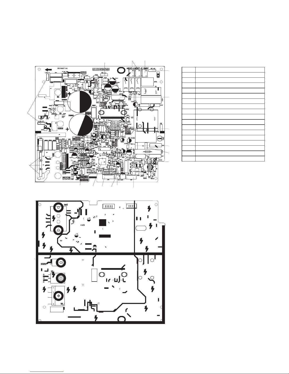
NO NAME
1
Interface of electronic expansion valve
2
Overload interface of compressor
3 Terminal of DRED
4
Interface of temperature sensor
5
Main board of IC
6 Eeprom
7
Interface of compressor wire
WVU
8
Reactor wiring terminal
9 DRED
Live wire interface
10
Interface of electric heating
11
4-way valve terminal
12 DRED
Interface of netural wire
13
Terminal of outdoor fan
14
Interface of earthing wire
15
Live wire interface
16
Neutral wire terminal
17
Communication wire
1
2
3
4
5
6
7
8
9
10 11
12
13
14
15
16
17
Outdoor Unit
● Top view
● Bottom view
 Loading...