


EN
OWNER’S MANUAL
Split Air Conditioner
Winner Series
M
ODELS
For proper operation, please read and keep this manual carefully.
Designed by Cooper&Hunter International Corporation, Oregon, USA
www.cooperandhunter.com
:
CH-S09FTX5
CH-S12FTX5
CH-S18FTX5
CH-S24FTX5

CONTENTS
1. IMPORTANT INFORMATIONS . ......................................................................................................................... 1
2. COMPONENTS . .................................................................................................................................................
3. DISPLAY . ............................................................................................................................................................
4. REMOTE CONTROLLER DESCRIPTION . . .......................................................................................................
4.1. Description of functions of remote controller buttons . . ....................................................................................
4.2. Name and functions of the display indicators . . ...............................................................................................
4.3. How to insert the batteries . ..............................................................................................................................
4.4. How to use the remote control to operate the unit . . ........................................................................................
4.5. Manual operation . ............................................................................................................................................
5. MAINTENANCE . .................................................................................................................................................
6. OPERATIONS AND PERFORMANCES .. ..........................................................................................................
7. TROUBLES AND CAUSES . ...............................................................................................................................
8. INSTALLATION . ...............................................................................................................................................
9. TEST OPERATION . .........................................................................................................................................
2
2
3
3
3
4
4
6
7
8
9
10
16

1. IMPORTANT INFORMATIONS
NORM: RISK:
Electrocution from live components. Personal injury from
Do not perform operations that involve opening the appliance.
Do not perform operations that involve removing the appliance
from its place of installation.
Do not start or stop the appliance by simply plugging it into or
out of the electricity mains.
Do not damage the power supply cable. Electrocution from live unsheathed wires.
burns due to overheated components or wounds caused by
sharp edges or protrusions.
Electrocution from live components. Personal injury from
burns due to cooling gases leaking from disconnected piping.
Electrocution from a damaged cable or plug or socket.
Do not leave anything on top of the appliance.
Do not climb onto the appliance. Personal injury due to the appliance falling.
Do not climb onto chairs, stools, ladders or unstable supports
to clean the appliance.
Do not attempt to clean the appliance without first turning it off
and unplugging it or switching the dedicated switch off.
Do not allow children or inexperienced people to use the
appliance.
Do not direct the air flow towards gas hobs or gas stoves.
Do not place your fingers in the air outlets or in the air inlet
grilles.
Do not drink the condensation water. Personal injury from poisoning.
Should the smell of burning be detected or smoke exit the
appliance, disconnect it from the electricity supply, open all
windows and call in the technician.
Do not perform operations that involve removing the appliance
from its place of installation.
Do not leave anything on top of the appliance.
Do not use any insecticides, solvents or aggressive detergents
to clean the appliance.
Do not use the appliance for any use other than normal
domestic use.
Do not allow children or inexperienced people to use the
appliance.
Do not direct the air flow towards valuable articles, plants or
animals.
Do not use the air conditioning unit for extended periods of
time in conditions of more than 80% humidity.
Personal injury from an object falling off the appliance
following vibrations.
Personal injury from falling from a height or from cuts
(stepladders shutting accidentally).
Electrocution from live components.
Damage to the appliance due to improper use.
Explosions, fires or intoxication from the discharge of gas
leaking from the burner nozzle once the air flow has put the
flame out.
Electrocution from live components. Personal injury from cuts.
Personal injury from burns or smoke inhalation.
Flooding due to water leaking from disconnected piping.
Damage to the appliance or any objects underneath it due to
the appliance falling off from its place of installation.
Damage to the plastic and painted parts.
Damage to the appliance due to operation overload. Damage
to objects treated inappropriately.
Damage to the appliance due to improper use.
Damage or perishing due to excessive cold/heat, humidity,
ventilation.
Damage to objects due to excessive dripping of condensation
from the appliance.
1

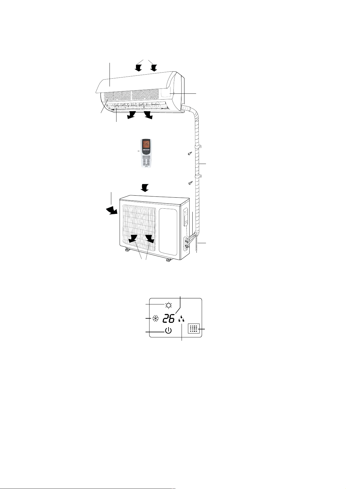
2. COMPONENTS
(6)
(2)
INDOOR UNIT
(5)
(12 )
(11)
(4)
(1)
(7)
(3)
(8)
(1) Air intake
(2) Front panel
(3) Control panel
(4) Air outlet
(5) Air flow louver
(6) Air filter
(7) Air intake
(8) Connecting pipe
(9) Drain
(10) Air outlet
(11) Air intake
(12) Remote controller
(9)
(10)
OUTDOOR UNIT
3. DISPLAY
(5)
(3)
(4)
(2)
(6)
(1) LED signal receiver
(2) Operation indicator
This indicator flashes after power is on and illuminates when the unit is in operation.
(3) Heating indicator
This indicator illuminates during the operation in heating mode.
(4) Cooling indicator
This indicator illuminates during the operation in cooling mode.
(5) Setting temperature indicator
It displays the setting temperature during the operation of the air conditioner.
(6) Dehumidification indicator
It illuminates during the operation in dehumidification mode.
(1)
2
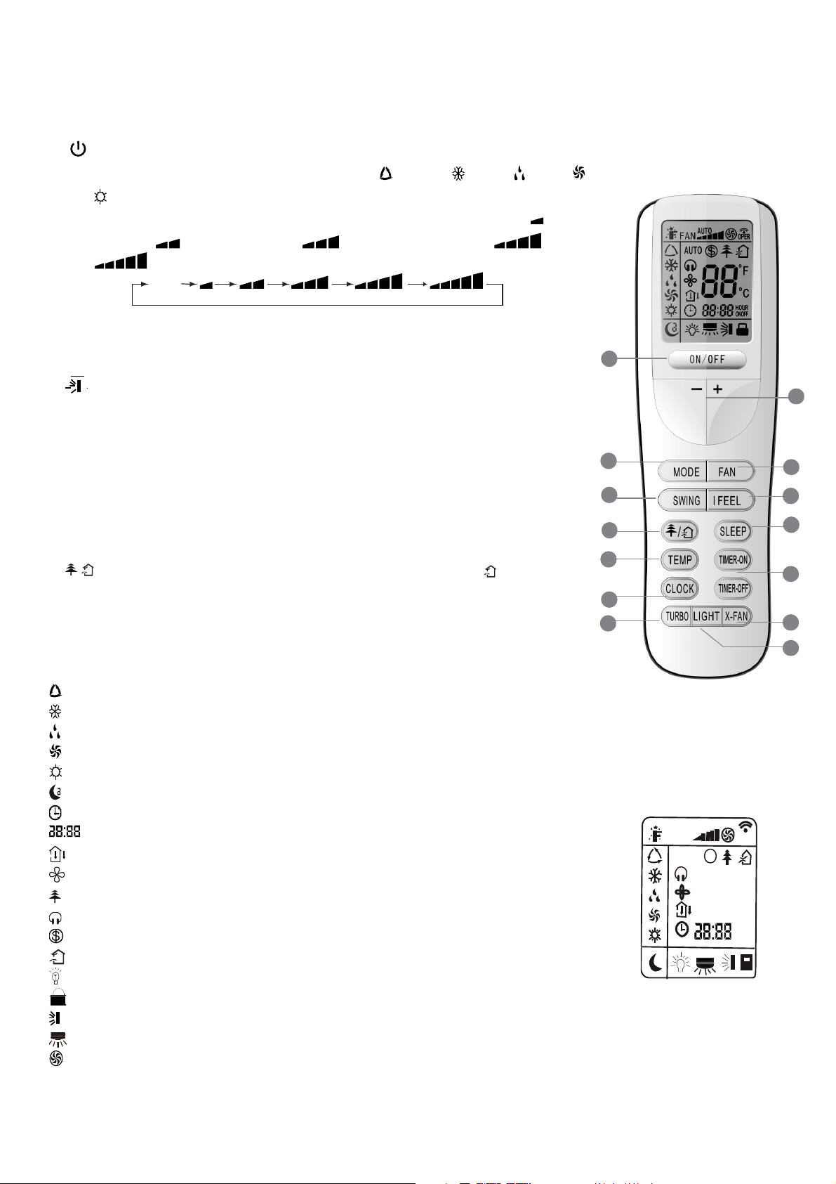
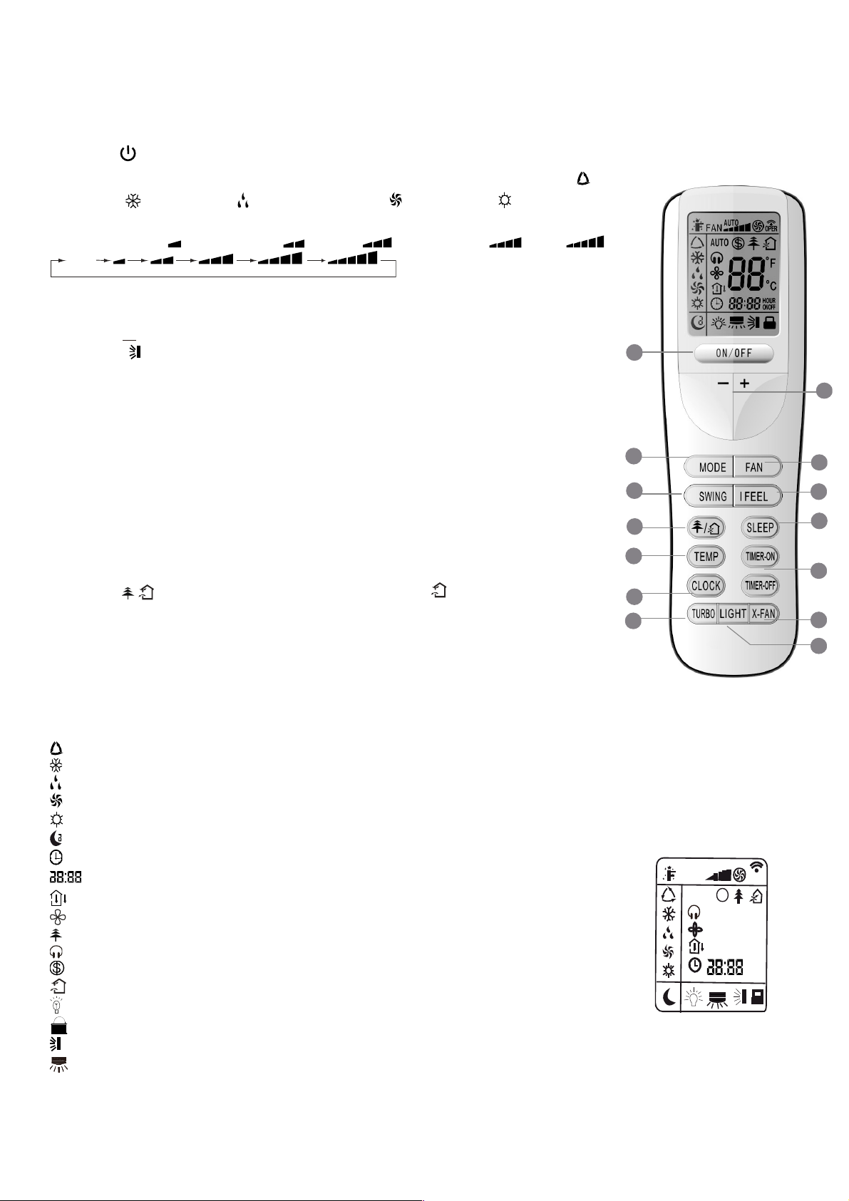
4. REMOTE CONTROLLER DESCRIPTION
4.1. Description of functions of remote controller buttons
①
button to turn the air conditioner on and off.
②
MODE button to select the operating mode: AUTO “ ”, COOL “ ”, DRY “ ”, FAN “ ”,
HEAT “ ”.
③
FAN button to set the fan speed in the sequence that goes from Auto, Low ( ), Low-
REMOTE CONTROLLER
Medium speed ( ), Medium speed ( ), Medium-High speed (
speed (
).
Auto
④
TURBO button used to enable/disable the rapid cooling or heating mode.
⑤
ADJUSTING "
increasing, "▼" decreasing.
⑥
button used to set up and down swing angle.
⑦ SLEEP
conditioner.
⑧ IFEEL
⑨
TIMER ON / TIMER OFF selection buttons. Used to set auto-off/auto-on timer.
⑩
CLOCK button is used to set the current time.
⑪ X-FAN
⑫
⑬
⑭
TEMP button, press it to show the set point temperature on the unit’s display.
button to set/cancel the Sleep mode regardless of the operating mode of the
button to enable/disable the IFEEL mode.
button press it to begin/stop indoor fan which is used to dry the components
LIGHT button used to turn on or off the unit’s display.
/ button to set HEALTH/AIR function for air cleaning / for air change ( not available).
▲/▼"
buttons to adjust ambient temperature and the timer: "▲"
), High
2
13
14
10
4
1
5
3
6
8
7
9
11
12
4.2. Name and functions of the display indicators
: AUTO mode indicator
: COOL mode indicator
: DRY mode indicator
: FAN mode indicator
: HEAT mode indicator
: SLEEP mode indicator
: CLOCK indicator
H
U
R
O
N
O
O
-
F
F
: TIMER ON-OFF mode indicator
: TEMP indicator
: FAN mode indicator
: AIR CLEANER mode indicator
: QUIET mode indicator
: 8°C Heating function indicator
: AIR RENEWING mode indicator
: LIGHT mode indicator
: LOCK indicator
: Up and down air deflector indicator
: Left and right air deflector indicator
: TURBO mode indicator
(not available).
(not available)
(not available).
DISPLAY
A
U
O
T
FA
N
AU
TO
$
88
6
O
P
E
R
°
F
°
C
H
O
U
R
N
O
O
-
F
F
3

: Signal sent confirmation LED
: IFEEL mode indicator
FAN : Fan Speed indicator
: Temperature display indicator
4.3. How to insert the batteries
Use two new alkaline type batteries with AAA 1,5V.
①
Slide down the cover of the battery compartment.
②
and ③ Remove the used batteries and insert new ones correctly.
④
Reattach the cover by sliding it back into its position.
Notes
♦ Do not use old batteries or different type batteries. Such a use may cause remote
control wrong functioning.
♦ If you do not use the remote control more than two weeks, remove the batteries.
Damages may be caused by possible leakages.
♦ Replace batteries when no "beep" is received from the indoor unit or if the
transmission indicator on the remote controller fails to light.
4.4. How to use the remote control to operate the unit
● SWITCHING THE UNIT ON AND OFF
Press the button to switch the unit on or off.
● SETTING THE OPERATING MODE
By pressing the Mode button several times it is possible to change the unit operating mode. The selected operating mode
symbol appears on the display.
2
1
3
4
→ → → →
: automatic mode
: cooling mode
: dehumidification mode
: fan only mode
: heating mode
When the automatic programme AUTO is selected, the unit may operate in COOLING or HEATING mode depending on the
temperature difference in place between the ambient temperature and the temperature selected on the remote control.
When the cooling mode is selected, the unit operates with a free temperature setting, lowering the ambient temperature.
When the dehumidification mode is selected, the unit operates with a free temperature setting, progressively lowering the
ambient temperature and humidity. When the dehumidification mode is in operation, the FAN button cannot be used. When
the heating mode is selected, the unit operates with a free temperature setting, raising the ambient temperature. When
the fan mode is selected, the unit operates without temperature settings, simply blowing air through the environment
IMPORTANT!
♦ The unit fan stops when the set temperature is reached and is then automatically reactivated at minimum
speed to prevent air stratification phenomena in the vicinity of the appliance.
♦ When the COOLING,
ANTI-HEATING mode is present. When the HEATING mode is selected, the fan may not start up straight away
because the ANTI-COOLING mode is present.
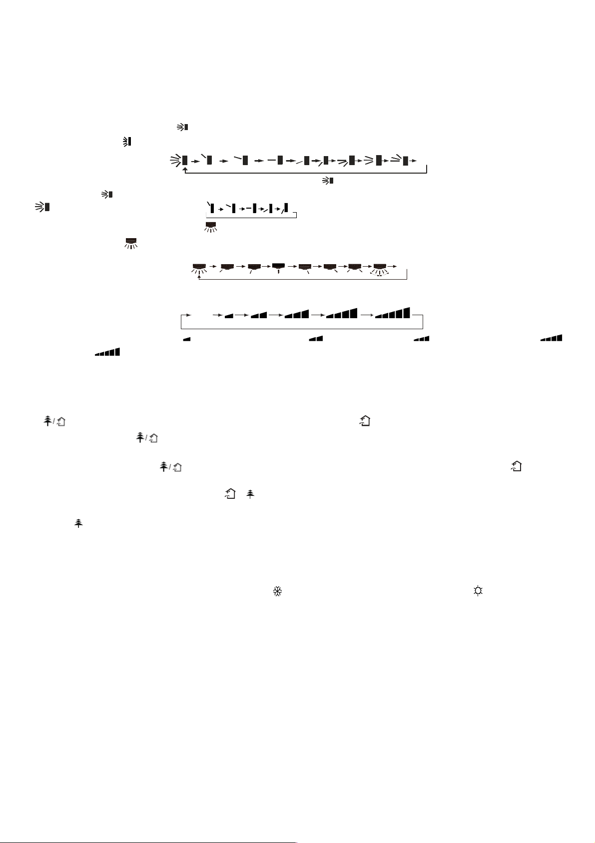
● SETTING THE LOUVERS
In order to obtain optimal air distribution, adjust the motorised louvers, making sure that the air flow is not directly pointed at
anyone. For the motorised louvers, proceed as follows:
DEHUMIDIFICATION mode is selected, the fan may not start up straight away because the
.
4

1) Press the button to set swing up and down angle, which circularly changes as below:
F
OF
Note: This remoter is universal. If any command , or is sent out, the unit will carry out the command as .
indicates the guide louver swings as:
2) Press the button to set left and right swig angle, which circularly changes as below (not available):
OFF
● SETTING THE FAN
By pressing the FAN button several times it is possible to adjust the fan speed between the three available speeds, or to
activate the AUTO mode. The operating mode appears on the display:
Auto
Auto, Low ( ), Low-Medium speed ( ), Medium speed ( ), Medium-High speed ( ), High speed ( ).
● IFEEL FUNCTION SETTING
Press this button to turn on IFEEL function. The unit automatically adjusts temperature according to the sensed
temperature. Press this button again to cancel IFEEL function.
● FUNCTION (the function of air renewing
is not available)
Press this button to achieve the on and off of healthy and scavenging functions in operation status. Press this button for the
first time to start scavenging function; LCD displays “ ”. Press the button for the second time to start healthy and
scavenging functions simultaneously; LCD displays “ ” and “
”. Press this button for the third time to quit healthy and
scavenging functions simultaneously. Press the button for the fourth time to start healthy function; LCD display “ ”. Press
this button again to repeat the operation above.
● SLEEP MODE SETTING
SLEEP mode can be set in COOLING or HEATING operation mode. This function gives you a more comfortable
environment for sleep.
In SLEEP mode,
♦ Fan speed is automatically set at low speed.
♦ Press the "SLEEP" button to set the unit to the sleep mode. The SLEEP indicator will light up on the display. The
temperature increases/decrease in cooling/heating mode operation by 1°C at set intervals. After reaching 2°C the unit
maintains this temperature through to the eighth hour (8 hours) of operation in the "SLEEP" mode and then switches off
automatically.
● TEMP FUNCTION
Press TEMP button to show the set point temperature, indoor ambient temperature and outdoor ambient temperature on the
unit’s display.
Note: Outdoor ambient temperature is only displayed for some models.
● CLOCK SETTING
To adjust the real time press CLOCK button, then use ''▲'' and ''▼'' buttons to get the correct time.
♦ Press the button ''▲'' / ''▼'' once to increase/decrease the time setting by 1 minute.
♦ Press the button ''▲'' / ''▼'' for 2 seconds to increase/decrease the time setting by 10 minutes.
♦ Press CLOCK button again the real time is set.
● TIMER MODE SETTING
Push the buttons TIMER to set the timer programming as wished in order to switch on and off the air conditioner at the
desired time.
- How to set TIMER ON
TIMER ON button can be used to set the timer programming as wished in order to switch on the appliance at your desired
time.
1) Press TIMER ON button, "ON" flashes on the LCD, then you can press the ''▲'' or ''▼'' buttons to select your desired
5

time for appliance on.
h
♦ Press the ''▲'' / ''▼'' button once to increase or decrease the time setting by 1 minute.
♦ Press the button ''▲'' / ''▼'' for 2 seconds to increase/decrease the time setting by 10 minutes.
Note: If you don't set the time in 10 seconds after you press TIMER ON button, the remote controller will exit the TIMER ON
mode automatically.
2) When your desired time displayed on LCD, press the TIMER ON button and confirm it, a beep can be heard and then the
TIMER indicator "ON" the indoor unit stops flashing.
3) After the set timer displayed, the clock will be displayed on the LCD of the remote controller instead of set timer.
- How to cancel TIMER ON
Press the TIMER ON button again, a "beep" can be heard and the indicator disappears, the TIMER ON mode has been
cancelled.
Note: It is similar to set TIMER OFF; you can make the appliance switch off automatically at your desired time.
● TURBO MODE SETTING:
♦ TURBO mode is used to start or stop fast cooling and heating at high fan speed.
♦ In Turbo mode, you can set airflow direction or timer. If you want to exit from TURBO mode, press any - TURBO, MODE,
FAN or button, the display will return to the original mode.
● LIGHT FUNCTION
Press LIGHT button to turn on the display's light and press this button again to turn off the display's light. If the light is turned
on, is displayed. If the light is turned off,
disappears.
● X-FAN FUNCTION
Pressing X-FAN button in COOL or DRY mode, the icon is displayed and the indoor fan will continue operation for 10
minutes in order to dry the indoor unit even though you have turned off the unit.
After electrification, X-FAN OFF is defaulted. X-FAN is not available in AUTO, FAN or HEAT mode.
● LOCK FUNCTION
Press the ''▲'' and ''▼'' buttons at the same time to block the last setting operation by the remote controller.
All the buttons disabled, including the button. Press the ''▲'' and ''▼'' buttons again to enable the buttons functions.
● °C / °F FUNCTION
Press the ''MODE'' and ''▼'' buttons at the same time with the unit off to choose the display of temperature in °C and °F.
● ENERGY-SAVING FUNCTION
Press “TEMP” and “CLOCK” simultaneously in COOL mode to start energy-saving function.
Nixie tube on the remote controller displays ''SE''. Repeat the operation to quit the function.
● 8°C HEATING FUNCTION
Press “TEMP” and “CLOCK” simultaneously in HEAT mode to start 8°C Heating Function Nixie tube on the remote
controller displays and a selected temperature of ''8°C''.
(46 if Fahrenheit is adopted). Repeat the operation to quit the function.
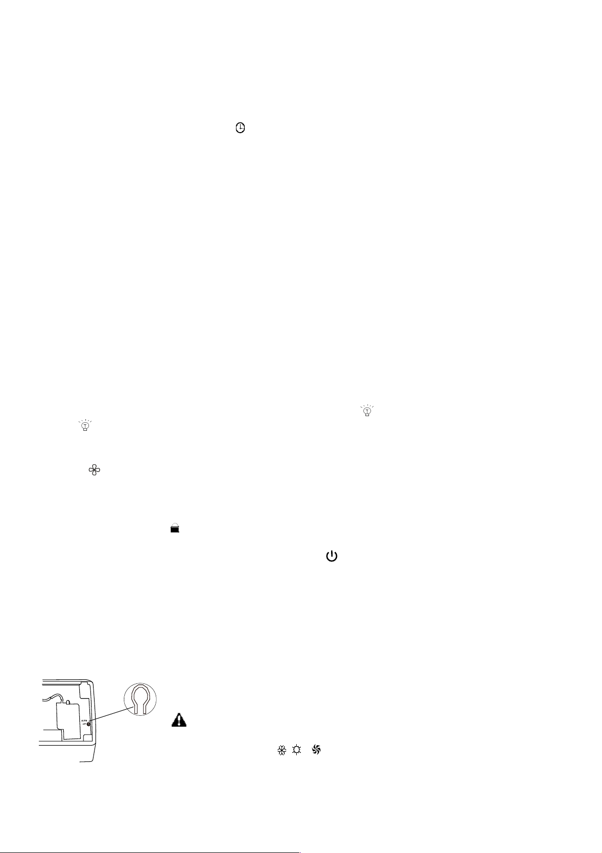
4.5. Manual operation
Manual operation can be used temporarily in case you cannot find the remote controller or its batteries are exhausted.
1. Open and lift the front panel up to an angle until it remains fixed with a clicking sound.
2. One press of the manual control button will lead to the forced AUTO operation.
3. Close the panel firmly to its original position.
Manual switc
CAUTION:
● Once you push the manual button, the operation mode will be selected according to
the room temperature as: COOL, HEAT, FAN.
● Press the button to stop the operation of the air conditioner.
6
5. MAINTENANCE
Household
Dra in
Cl eaner
No
WARNING
It is necessary to stop the air conditioner and disconnect the power supply before
cleaning.
Cleaning the indoor unit and remote controller
CAUTIONS
● Use a dry cloth to wipe the indoor unit and remote controller.
● A cloth dampened with cold water may be used on the indoor unit if it is very dirty.
● The front panel of the indoor unit can be removed and cleaned with water. Then
wipe it with a dry cloth.
● Do not use a chemically treated cloth or duster to clean the unit.
● Do not use benzene, thinner, polishing powder, or similar solvents for cleaning.
These may cause the plastic surface to crack or deform.
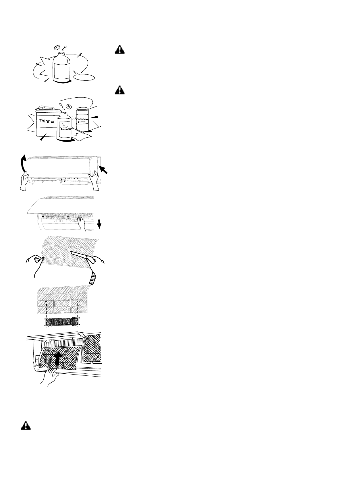
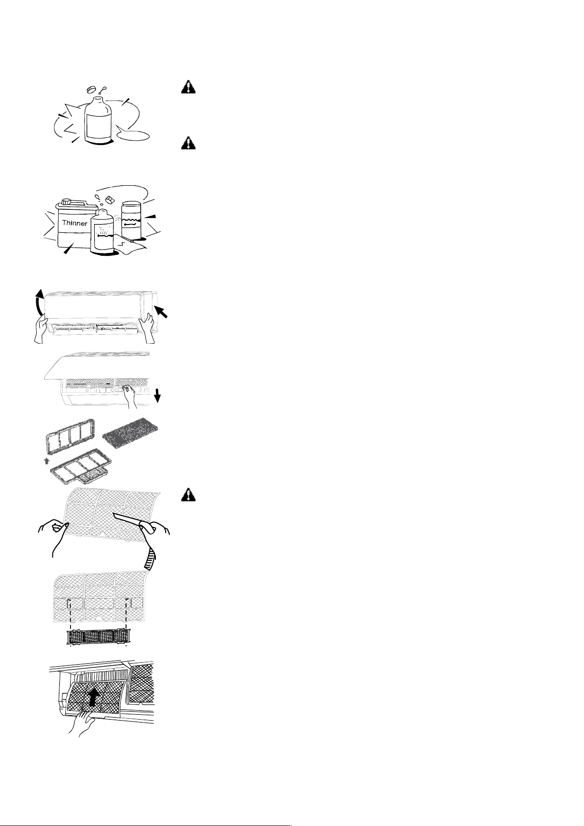
Cleaning the air filter
A clogged air filter reduces the cooling efficiency of this unit. Please clean the filter
once every 2 weeks.
1. Lift the indoor unit panel up to an angle until it stops with a clicking sound.
2. Take hold of the handle of the air filter and lift it up slightly to take it out from the
filter holder, and then pull it downwards.
3. Remove the AIR FILTER from the indoor unit.
- Clean the AIR FILTER once two weeks.
- Clean the AIR FILTER with a vacuum cleaner or water, and then dry it up cool place.
4. Remove the healthy filter from its support frame as shown in the Figure on the left
(Not applicable to the units without electrostatic filter).
Do not touch this Electrostatic Filter within 10 minutes after opening the inlet grille; it
may cause an electric shock.
● Clean the electrostatic filter with mild detergent or water and dry in the sunlight for
two hours.
● Before re-install the Electrostatic Filter, check whether the corona line or support
frame is damaged or not.
5. Install the air freshening filter back into position.
6. Insert the upper portion of air filter back into the unit taking care that the left and
right edges line up correctly and place filter into position.
Maintenance
If you plan to idle the unit for a long time, perform the following:
(1) Operate the fan for about half a day to dry the inside of the unit.
(2) Stop the air conditioner and disconnect power. Remove the batteries from the
remote controller.
(3) The outdoor unit requires periodic maintenance and cleaning. Do not attempt to do
this yourself. Contact your dealer or servicer.
Checks before operation
Check that the wiring is not broken off or disconnected.
Check that the air filter is installed.
Check if the air outlet or inlet is blocked after the air conditioner has not been used for a long time.
CAUTIONS
Do not touch the metal parts of the unit when removing the filter. Injuries can occur when handling sharp metal edges.
7

Do not use water to clean inside the air conditioner. Exposure to water can destroy the insulation, leading to possible
electric shock.
When cleaning the unit, first make sure that the power and circuit breaker are turned off.
6. OPERATIONS AND PERFORMANCES
The following events may occur during normal operation.
1. Protection of the air conditioner.
Compressor protection
● The compressor can't restart for 3 minutes after it stops.
Anti-cold air (Cooling and heating models only)
● The unit is designed not to blow cold air on HEAT mode, when the indoor heat exchanger is in one of the following three
situations and the set temperature has not been reached.
A) When heating has just starting.
B) Defrosting.
C) Low temperature heating.
● The indoor or outdoor fan stop running when defrosting (Cooling and heating models only). Defrosting (Cooling and
heating models only)
● Frost may be generated on the outdoor unit during heat cycle when outdoor temperature is low and humidity is high
resulting in lower heating efficiency of the air conditioner.
● During this condition air conditioner will stop heating operation and start defrosting automatically.
● The time to defrost may vary from 4 to 10 minutes according to the outdoor temperature and the amount of frost build-up
on the outdoor unit.
2. A white mist coming out from the indoor unit
● A white mist may generate due to a large temperature difference between air inlet and air outlet on COOL mode in an
indoor environment that has a high relative humidity.
● A white mist may generate due to moisture generated from defrosting process when the air conditioner restarts in HEAT
mode operation after defrosting.
3. Low noise of the air conditioner
● You may hear a low hissing sound when the compressor is running or has just stopped running. This sound is the sound
of the refrigerant flowing or coming to a stop.
● You can also hear a low "squeak" sound when the compressor is running or has just stopped running. This is caused by
heat expansion and cold contraction of the plastic parts in the unit when the temperature is changing.
● A noise may be heard due to louver restoring to its original position when power is first turned on.
4. Dust is blown out from the indoor unit.
This is a normal condition when the air conditioner has not been used for a long time or during first use of the unit.
5. A peculiar smell comes out from the indoor unit.
This is caused by the indoor unit giving off smells permeated from building material, from furniture, or smoke.
6. The air conditioner turns to FAN only mode from COOL or HEAT (For cooling and heating models only) mode.
When indoor temperature reaches the temperature setting on air conditioner, the compressor will stop automatically, and
the air conditioner turns to FAN only mode. The compressor will start again when the indoor temperature rises on COOL
mode or falls on HEAT mode (For cooling and heating models only) to the set point.
7. Dripping water may generate on the surface of the indoor unit when cooling in a high relatively humidity (relative
humidity higher than 80%).
Adjust the horizontal louver to the maximum air outlet position and select HIGH fan speed.
8. Heating mode (For cooling and heating models only)
The air conditioner draws in heat from the outdoor unit and releases it via the indoor unit during heating operation. When the
outdoor temperature falls, heat drawn in by the air conditioner decreases accordingly. At the same time, heat loading of the
air conditioner increases due to larger difference between indoor and outdoor temperature. If a comfortable temperature
can't be achieved by the air conditioner, we suggest you use a supplementary heating device.
8

9. Auto-restart function
Power failure during operation will stop the unit completely.
For the unit without Auto-restart feature, when the power restores, the OPERATION indicator on the indoor unit starts
flashing. To restart the operation, push the button on the remote controller. For the unit with Auto-restart feature, when
the power restores, the unit restarts automatically with all the previous settings preserved by the memory function.
10. Lightning or a car wireless telephone operating nearby may cause the unit to malfunction.
Disconnect the unit with power and then re-connect the unit with power again. Push the button on the remote controller
to restart operation.
7. TROUBLES AND CAUSES
Stop the air conditioner immediately if one of the following faults occur. Disconnect the power and contact the nearest
customer service center.
OPERATION indicator or other indicators flash rapidly (5 times every second) and this flash
cannot be fixed by disconnecting the power, and then connect it again
Trouble
Fuse blows frequently or circuit breaker trips frequently
Other objects or water penetrate the air conditioner
The remote controller won’t work or works abnormally
Other abnormal situations
Malfunctions Cause What should be done?
Power cut Wait for power to be restored
Unit may have become unplugged. Check that plug is securely in wall receptable
Fuse may have blown. Replace the fuse
Unit does not start
Battery in remote controller may have
Replace the battery
been exhausted.
The time you have set with timer is
Wait or cancel timer setting
incorrect.
Inappropriate temperature setting Set temperature correctly
Air filter is blocked Clean the air filter
Unit not cooling or heating
room very well while air
flowing out from the air
Doors or Windows are open Close the doors or windows
Air inlet or outlet of indoor or outdoor unit
Clear obstructions away first, then restart the unit
has been blocked
conditioner
Compressor 3 minutes protection has
Wait
been achieved
If the trouble has not been corrected, please contact a local dealer or the nearest customer service center. Be sure to inform
them of the detailed malfunctions and unit model.
Notes: Do not attempt to repair the unit yourself. Always consult an authorised service provider.
9

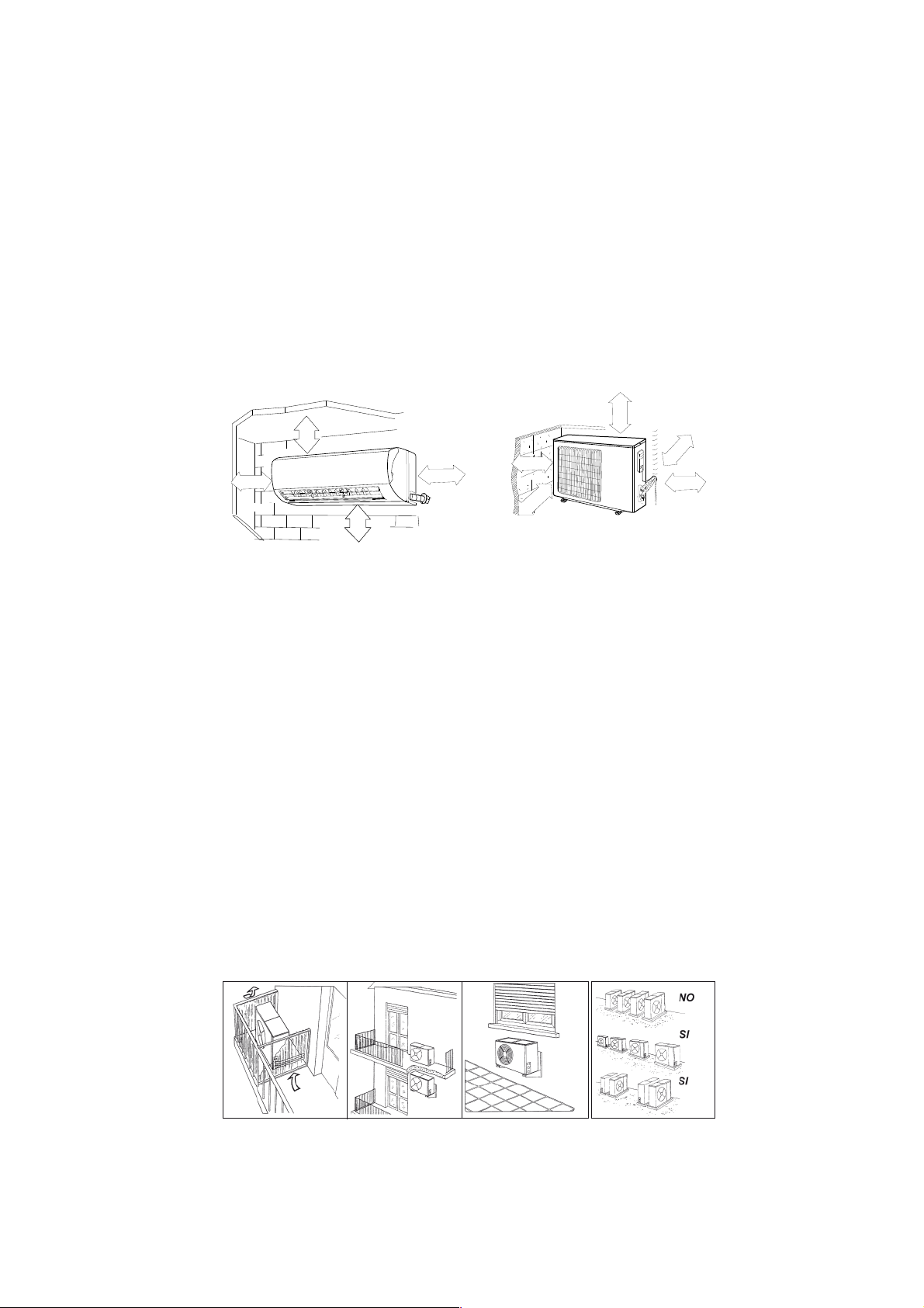
8. INSTALLATION
Indoor unit
● Do not expose the indoor unit to heat or steam.
● Select a place where there are no obstacles in front or around the unit.
● Make sure that condensation drainage can be conveniently routed away.
● Do not install near a doorway.
● Ensure that the space on the left and right of the unit is more than 12 cm.
● Use a stud finder to locate studs to prevent unnecessary damage to the wall.
● A minimum pipe run of 3 metres is required to minimise vibration & excessive noise.
● The indoor unit should be installed on the wall at a height of 2.3 metres or more from the floor.
● The indoor unit should be installed allowing a minimum clearance of 15cm from the ceiling.
● Any variations in pipe length will/may require adjustment to refrigerant charge.
60 cm
≤
m
≤ 15 cm
m
c
5
1
m
c
15
≤
cm
2
0
5
2
≤
≤
≤
60 cm
5
0
≤
0
2
m
c
0
Outdoor unit
If an awning is built over the outdoor unit to prevent direct sunlight or rain exposure, make sure that heat radiation from the
condenser is not restricted.
● Ensure that the clearance around the back of the unit is more than 30 cm and left side is more than 30 cm. The front of
the unit should have more than 200 cm of clearance and the connection side (right side) should have more than 60 cm of
clearance. Do not place animals and plants in the path of the air inlet or outlet.
● Take the air conditioner weight into account and select a place where noise and vibration will not be an issue.
● Select a place so that the warm air and noise from the air conditioner do not disturb neighbours.
● Install the outdoor unit on a rigid base to prevent increasing noise level and vibration.
● Determine the air outlet direction where the discharged air is not blocked.
● In the case that the installation place is exposed to strong wind such as a seaside, make sure the fan operating properly
by putting the unit lengthwise along the wall or using a dust or shield plates.
● Specially in windy area, install the unit to prevent the admission of wind.
● If need suspending installation, the installation bracket should accord with technique requirement in the installation
bracket diagram. The installation wall should be solid brick, concrete or the same intensity construction, or actions to
reinforce, damping supporting should be taken. The connection between bracket and wall, bracket and the air conditioner
should be firm, stable and reliable.
● Be sure there is no obstacles which block radiating air.
c
5
1
≤
≤ 15 cm
10
Rooftop installation:
● If the outdoor unit is installed on a roof structure, be sure to level the unit. Ensure the structure and anchoring method are
adequate for the unit location.
● Consult local codes regarding rooftop mounting.
● If the outdoor unit is installed on roof structures or external walls, this may result in excessive noise and vibration, and
may also be classed as a non-serviceable installation.
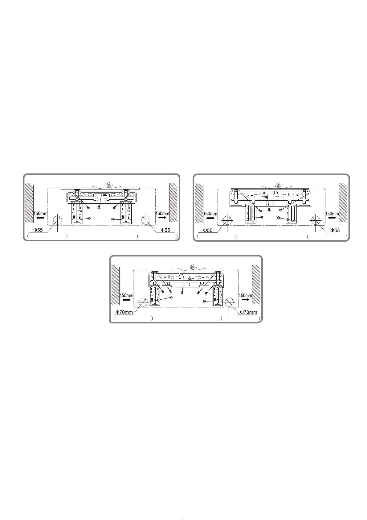
1. Fit the installation Plate
1. Fit the installation plate horizontally on structural parts of the wall with spaces around the installation plate.
2. If the wall is made of brick, concrete or the like, drill 5 holes in the wall of 5 mm diameter. Insert Clip anchor for
appropriate mounting screws.
3. Fit the installation plate on the wall with type "ST4.2X25TA" screws. Fit the Installation Plate and drill holes in the wall
according to the wall structure and corresponding mounting points on the installation plate. (Dimensions are in "mm" unless
otherwise stated).
Mod. 2600 W, 3500 W
Mod. 5300 W
Wall
Space
to the
wall
above
Left
Rear piping hole
Mark in the middle of it
Level meter
Rear piping hole
Space
to the
wall
above
Right
Wall
Wall
Space
to the
wall
above
Left
Rear piping hole
Mark in the middle of it
Level meter
Rear piping hole
Wall
Space
to the
wall
above
Right
Mod. 7000 W
Wall
Mark in the middle of it
Space
to the
wall
above
Left
Rear piping hole
Level meter
Rear piping hole
Wall
Space
to the
wall
above
Right
Drill a hole in the wall
1. Determine hole positions according to the diagram detailed in the figure above. Drill one (1) hole (the diameter is
indicated in the installation plate) slanting slightly to outdoor side.
2. Always use wall hole conduit when drilling metal plate or the like.
Connective Pipe and Drainage Installation
1. Run the drain hose sloping downward. Do not install the drain hose as illustrated below.
2. When connecting extension drain hose, insulate the connecting part of extension drain hose with a shield pipe, do not let
the drain hose slack.
Connective pipe
1. For the left-hand and right-hand piping, remove the pipe cover from the side panel.
● Explain to clients that the pipe cover must be kept as it may be used when relocate the air conditioner to any other place.
2. For the rear-right-hand and rear-left-hand piping, install the piping as shown. Bend the connective pipe to be laid at 43mm
height or less from the wall.
3. Fix the end of the connective pipe. (Refer to Tightening Connection in REFRIGERANT PIPING CONNECTION).
11

Indoor unit installation
1. Pass the piping through the hole in the wall.
2. Put the upper claw at the back of the indoor unit on the upper hook of the
installation plate, move the indoor unit from side to side to see that it is securely
hooked.
3. Piping can easily be made by lifting the indoor unit with a cushioning material
between the indoor unit and the wall. Get it out after piping.
4. Push the lower part of the indoor unit up on the wall. Then move the indoor unit from side to side, up and down to check if
it is hooked securely.
Settlement of outdoor unit
Anchor the outdoor unit with a bolt and nut 10 or 8 tightly and horizontally on a concrete or rigid mount.
Drain joint installation
Fit the seal into the drain elbow, then insert the drain joint into the base pan hole of outdoor unit, rotate 90 to securely
assemble them. Connecting the drain joint with an extension drain hose (Locally purchased), in case of the water draining
off the outdoor unit during the heating mode.
Piping and wrapping
Bundle the tubing, connecting cable, and drain hose with tape securely.
● Because the condensed water from rear of the indoor unit is gathered in pending box and is piped out of room. Do not put
anything else in the box.
CAUTION
● Connect the indoor unit first, then the outdoor unit.
● Do not allow the piping to let out from the back of the indoor unit.
indoor unit
indoor and outdoor
connectionwires
● Be careful not to let the drain hose slack.
● Heat insulated both of the auxiliary piping.
● Be sure that the drain hose is located at the lowest side of the bundle.
Locating at the upper side can cause drain pan to over flow inside the unit.
● Never intercross nor intertwist the power wire with any other wiring.
gas pipe
with isulation
band
liquid pipe
with isulation
drain hose
● Run the drain hose sloped downward to drain out the condensed water
smoothly.
● The power cables should not come into contact with the tubing.
Models
1 x 1 DC INV.
2600 W
3500 W
5300 W
7000 W
Connective pipe length max
without additional refrigerant (m)
5 15 10 20 Φ6,35/Φ9,52
5 20 10 20 Φ6,35/Φ9,52
5 25 10 20 Φ6,35/Φ12,7
5 25 10 50 Φ6,35/Φ16
Allowed connective pipe
length (m)
Max. difference
in level (m)
Additional amount
of refrigerant (g/m)
Φliquid/Φgas
12
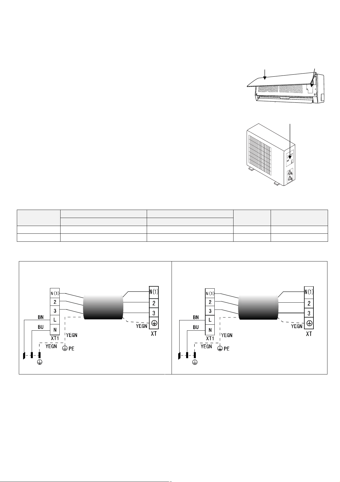
Wiring connections
Connect the cable to the indoor unit
1. Indoor/Outdoor connection cable should be H07RN-F type.
2. Lift the indoor unit panel up and remove the screw, then remove the window cover
Front panel Terminal
3. Connect cables according to their marks to terminals.
4. Wrap those cables not connected with terminals with insulation tapes, so that they will
not touch any electrical components.
Indoor unit
Connect the cable to the outdoor unit
Access door terminal
1. Remove the electric parts cover from the outdoor unit.
2. Connect the connective cables to the terminals as identified with their respective
matched numbers on the terminal block of indoor and outdoor units.
2. Power supply connection cable should be H07RN-F.
3. To prevent the ingress of water, from a loop of the connective cable as illustrated in
the installation diagram of indoor and outdoor units.
4. Insulate unused cords (conductors) with PVC-tape. Process them so they do not
Outdoor unit
touch any electrical or metal parts.
Wires specifications
Model (W)
2600 W, 3500 W 3 x 1.5 mm² 4 x 0,75 mm² To outdoor 20 A (240V)
5300 W, 7000 W 3 x 1.5 mm² 4 x 0,75 mm² To outdoor 25 A (240V)
Power connecting cable Indoor - outdoor connecting cable
Section Section
Main power
supply
Air switch capacity
(A)
Wiring diagrams
OUTDOOR UNIT
TERMINAL BLOCK
BU
L N
POWER SUPPLY
Mod. 2600 W, 3500 W Mod. 5300 W, 7000 W
BK
BN
INDOOR UNIT
TERMINAL BLOCK
BU
BK
BN
OUTDOOR UNIT
TERMINAL BLOCK
L N
BU
BK
BN
POWER SUPPLY
INDOOR UNIT
TERMINAL BLOCK
BU
BK
BN
13

Refrigerant piping connection
1. Flaring work
Main cause for refrigerant leakage is due to defect in the flaring work. Carry out
correct flaring work using the following procedure:
A: Cut the pipes and the cable.
1. Use the piping kit accessory or pipes purchased locally.
2. Measure the distance between the indoor and the outdoor unit.
3. Cut the pipes a little longer than the measured distance.
4. Cut the cable 1.5m longer than the pipe length.
B: Burr removal
1. Completely remove all burrs from the cut cross section of pipe/tube.
2. Put the end of the copper tube/pipe in a downward direction as you remove burrs
in order to avoid dropping burrs into the tubing.
C: Putting nut on
Remove flare nuts attached to indoor and outdoor unit, and then put them on pipe/tube having completed burr removal. (Not
possible to put them on after flaring work).
D: Flaring work
Firmly hold copper pipe in a die in the dimension shown in the table below.
Outer diam . (mm )
Φ 6,35
Φ 9,52
Φ 12,7
Φ 16
Tightening Connection
● Align the center of the pipes.
● Sufficiently tighten the flare nut with fingers, and then tighten it with a spanner
and torque wrench as shown.
CAUTION:
● Excessive torque can break nut depending on installation conditions.
A(mm)
Max. Min
1,3
1,6
1,8
2
0,7
1
1
1
Hex nut diam. (mm) Tightening torque (N.m)
Φ 6,35
Φ 9,52
Φ 12,7
15 ~ 20
31 ~ 35
50 ~ 55
Pipe
Φ 16
60 ~ 65
14

Air purging
r
Air and moisture in the refrigerant system have undesirable effects as indicated
below:
● Pressure in the system rises.
● Operating current rises.
● Cooling or heating efficiency drops.
● Moisture in the refrigerant circuit may freeze and block capillary tubing.
● Water may lead to corrosion of parts in the refrigeration system.
Therefore, the indoor unit and tubing between the indoor and outdoor unit must be
leak tested and evacuated to remove any non-condensable and moisture from the
system.
Air purging with vacuum pump
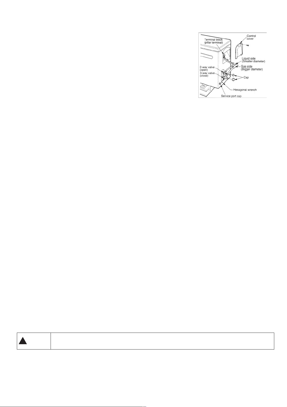
● Preparation
Check that each tube (both liquid and gas side tubes) between the indoor and
outdoor units have been properly connected and all wiring for the test run has been
completed. Remove the service valve caps from both the gas and the liquid side on
the outdoor unit.
Note that both the liquid and the gas side service valves on the outdoor unit are
kept closed at this stage.
● Pipe length and refrigerant amount:
● When relocate the unit to another place, perform evacuation using vacuum
pump.
Make sure the refrigerant added into the air conditioner is liquid form in any case.
Caution in handling the packed valve
● Open the valve stem until it hits against the stopper. Do not try to open it further.
● Securely tighten the valve stem cap with a spanner or the like.
● Valve stem cap tightening torque (See Tightening torque table in previous page).
When Using the Vacuum Pump
(For method of using a manifold valve, refer to its operation manual.)
1. Completely tighten the flare nuts, A, B, C, D, connect the manifold valve charge
hose to a charge port of the low-pressure valve on the gas pipe side.
2. Connect the charge hose connection to the vacuum pump.
3. Fully open the handle Lo of the manifold valve.
4. Operate the vacuum pump to evacuate. After starting evacuation, slightly loose
the flare nut of the Lo valve on the gas pipe side and check that the air is entering
(Operation noise of the vacuum pump changes and a compound meter indicates
0 instead of minus)
Outdoor unit
Pressure
gauge
Pressure
gauge
Indoor unit
Manifold gauge
Nitrogen gas cylinde
Indoor unit
Outdoor unit
Manifold gauge
Open
Vacuum pump
Charge hose
(in vertical position)
Close
15
5. After the evacuation is complete, fully close the handle Lo of the manifold valve
and stop the operation of the vacuum pump. Make evacuation for 15 minutes or more
and check that the compound meter indicates -76cmHg (1x10⁵Pa).
6. Turn the stem of the packed valve B about 45° counter clockwise for 6-7 seconds
after the gas coming out, and then tighten the flare nut again. Make sure the
pressure display in the pressure indicator is a little higher than the atmosphere
pressure.
7. Remove the charge hose from the Low pressure charge hose.
8. Fully open the packed valve stems B and A.
9. Securely tighten the cap of the packed valve.
9. TEST OPERATION
The test operation must be carried out after the entire installation has been completed.
Please confirm the following points before the test operation:
The indoor unit and outdoor unit are installed properly.
Tubing and wiring are correctly completed.
The refrigerant pipe system is leakage-checked.
The drainage is unimpeded.
The heating insulation works well.
The ground wiring is connected correctly.
The length of the tubing and the added stow capacity of the refrigerant have been recorded.
The power voltage fits the rated voltage of the air conditioner.
There is no obstacle at the outlet and inlet of the outdoor and indoor units.
The gas-side and liquid-side stop valves are both opened.
The air conditioner is pre-heated by turning on the power.
TEST OPERATION
■ Set the air conditioner under the mode of "COOLING" with the remote controller, and check the following points. If there is
any malfunction, please resolve it according to the chapter "TROUBLESHOOTING" of this Manual".
1) The indoor unit
a) Whether the switch on the remote controller works well.
b) Whether the buttons on the remote controller works well.
c) Whether the air flow louver moves normally.
d) Whether the room temperature is adjusted well.
e) Whether the indicator lights normally.
f) Whether the temporary buttons works well.
g) Whether the drainage is normal.
h) Whether there is vibration or abnormal noise during operation.
i) Whether the air conditioner heats well.
2) The outdoor unit
a) Whether there is vibration or abnormal noise during operation.
b) Whether any of the refrigerant is leaked.
CAUTION
A protection feature prevents the air conditioner from being activated for approximately 3 minutes when it
is restarted immediately after shut off.
16

ES
MANUAL DE USUARIO
Aire aconcicionado Split
Serie
Winner
MODELO
Gracias por escoger nuestro producto.
Para su correcto funcionamiento, lea y conserve este manual para
su consulta.
Diseñado por Cooper & Hunter International Corporation, Oregon, EE.UU.
www.cooperandhunter.com
:
CH-S09FTX5
CH-S12FTX5
CH-S18FTX5
CH-S24FTX5

ÍNDICE
1. INFORMACIONES IMPORTANTES . . . .............................................................................................................. 1
2. COMPONENTES . . .............................................................................................................................................
3. DISPLAY . . . ........................................................................................................................................................
4. MANDO A DISTANCIA . . ....................................................................................................................................
4.1. Descripción de las funciones de las teclas del mando a distancia . .................................................................
4.2. Descripción de los indicadores led de la pantalla . . .........................................................................................
4.3. Como insertar/remplazar las baterías . . . .........................................................................................................
4.4. Cómo usar el control remoto para operar la unidad . . .....................................................................................
4.5. Funcionamiento manual . . . .............................................................................................................................
5. MANTENIMIENTO . . ...........................................................................................................................................
6. OPERACIONES Y SERVICIOS . . ......................................................................................................................
7. PROBLEMAS Y SUS CAUSAS . . ....................................................................................................................
8. INSTALACIÓN . . ...............................................................................................................................................
9. PRUEBA DE FUNCIONAMIENTO . . . ...............................................................................................................
2
2
3
3
3
4
4
6
7
8
10
11
17

1. INFORMACIONES IMPORTANTES
NORMA RIESGOS
Fulguración por la presencia de componentes bajo
No realice operaciones que impliquen la apertura del
aparato.
tensión.
Lesiones personales como quemaduras debido a la
presencia de componentes recalentados o heridas
producidas porbordes y protuberancias cortantes.
Fulguración por la presencia de componentes bajo
No realice operaciones que impliquen laremoción del
aparato del lugar donde estáinstalado.
tensión.
Lesiones personales como quemaduras por
enfriamientodebido al escape de gas de los tubos
desconectados.
No ponga en funcionamiento o apague elaparato
conectándolo o desconectándolo dela alimentación
Fulguración por daño del cable, del enchufe, o del toma
eléctrica.
No dañe el cable de alimentación eléctrica.
Fulguración por la presencia de cables pelados bajo
tensión
No deje objetos sobre el aparato.
Lesiones personales por la caída del objeto como
consecuencia de las vibraciones
No suba sobre el aparato. Lesiones personales por una caída desde el aparato
No suba a sillas, taburetes, escaleras osoportes
inestables para efectuar la limpiezadel aparato.
Antes de realizar operaciones de limpieza delaparato,
apáguelo y desenchúfelo o desconecte el interruptor
correspondiente
No permita que los niños o personas inexper-tas utilicen
el aparato.
Lesiones personales por la caída desde lo alto o por
cortes(escaleras dobles)
Fulguración por la presencia de componentes bajo
tensión.
Daño del aparato por uso impropio.
Explosiones, incendios o intoxicaciones producidas por
No dirija el flujo de aire hacia encimeras oestufas a gas.
escape de gas de los picos de alimentación con llamas
apagadaspor el fl ujo de aire.
No introduzca los dedos en las bocas de salidade aire ni
en las rejillas de aspiración de aire.
Fulguración por la presencia de componentes bajo
tensión. Lesiones personales como cortes
No beba el agua de condensación. Lesiones personales como intoxicación.
En el caso en que se advierta olor a quemado o se vea
salir humo del aparato, desconecte el aparato, abra las
ventanas y llame altécnico.
No realice operaciones que impliquen laremoción del
aparato del lugar donde estáinstalado.
Lesiones personales provocadas por quemaduras o
inhalación de humo.
Inundaciones por pérdida de agua de los tubos
desconectados.
Daño del aparato o de los objetos que se encuentren
No deje objetos sobre el aparato.
debajode él, por la caída del aparato como
consecuencia de undesenganche de la fi jación.
No utilice insecticidas, solventes o detergentes
agresivos para la limpieza del aparato
No utilice el aparato con fi nalidades diferentesa las de
un uso doméstico normal.
No permita que los niños o personas inexper-tas utilicen
el aparato.
No dirija el fl ujo de aire hacia objetos de valor, plantas o
animales.
No use el acondicionador por mucho tiempoen
condiciones de humedad superior al 80%.
Daño de las partes de material plástico o pintadas.
Daño del aparato por sobrecarga de funcionamiento.
Daño de los objetos indebidamente tratados.
Daño del aparato por uso impropio.
Daño o deterioro por excesivo frío/calor, humedad o
ventilación.
Daño de objetos por el goteo debido a una excesiva
condensación en el aparato.
1
2. COMPONENTES
Unidad interior
(2)
(1)
(3)
(6)
(5)
(11)
(12 )
(4)
(10)
Unidad exterior
(7)
(8)
(9)
(1) Entrada de aire
(2) Panel delantero
(3) Control manual
(4) Salida de aire
(5) Deflector de aire
(6) Filtro de aire
(7) Entrada de aire
(8) Tubos de conexión
(9) Tubos desagüe
(10) Salida de aire
(11) Entrada de aire
(12) Mando a distacia
3. DISPLAY
(5)
(3)
(4)
(2)
(6)
(1) LED Señal receptor
(2) Operation indicator
Este piloto parpadea después de conectar la alimentación y se enciende cuando la unidad está funcionando.
(3) Heating indicator
Este indicador ilumina durante la operación en modo calefacción.
(4) Cooling indicator
Este indicador ilumina durante la operación en modo refrigeración.
(5) Setting temperature indicatore
Indica la temperatura elegida cuando está funcionando el acondicionador.
(6) Indicatore di deumidificazione
Este indicador ilumina durante la operación en modo deshumidificación.
(1)
2
4. MANDO A DISTANCIA
.
4.1. Descripción de las funciones de las teclas del mando a distancia
① La tecla
②
La tecla MODE (MODALIDAD) permite de seleccionar el modo de funcionamiento:
automático; en ventilación; en deshumidificación; en ventilación; en calefeccación
③ La tecla FAN (VENTILADOR) permite seleccionar la velocidad del ventilador:
Automática - Baja ( ), Baja – Media ( ), Media ( ), Media – Alta (
Auto
④ La tecla TURBO activa/desactiva la modalidad de refrigeración rápida.
⑤ La tecla "▲/▼" para seleccionar la TEMPERATURA consigue regular la temperatura
del cuarto: "
La tecla (oscilación arriba y abajo) sirve para activar/desactivar el movimiento
⑥
automático a arriba y abajo del deflector del aire.
Pulsar la tecla SLEEP (SUEÑO) para seleccionar/cancelar la función Sleep,
⑦
independientemente del modo en el que está funcionando el acondicionador.
La tecla IFEEL sirve para activar/desactivar la función IFEEL.
⑧
Las teclas de selección TIMER ON/TIMER OFF permiten ajustar el tiempo de encendido
⑨
/ apagamiento del acondicionador de forma automática.
La tecla CLOCK (RELOJ) permite programar el horario actual.
⑩
La tecla X-FAN (X-VENTILADOR) permite encender/apagar el ventilador interno; esta
⑪
función se utiliza para secar los componentes internos de la unidad interior.
⑫
La tecla LIGHT (LUZ) activa/desactiva la pantalla de la unidad.
⑬
La tecla / permite la purificación/recirculación del aire ( no
disponible).
⑭
La tecla TEMP permite visualizar, en la pantalla de la unidad, la
temperatura seleccionada y la temperatura ambiente.
enciende y apaga el acondicionador.
▲"
pulsándola aumenta, "
▼"
pulsándola disminuye.
), Alta (
).
2
13
14
10
4
1
5
3
6
8
7
9
11
12
4.2. Descripción de los indicadores led de la pantalla
: Indicador modalidad AUTO
: Indicador modalidad COOL/REFRIGERACIÓN
: Indicador modalidad DRY/DESHUMEDIFICACIÓN
: Indicador modalidad FAN/VENTILACIÓN
: Indicador modalidad HEAT/CALEFACCIÓN
: Indicador modalidad SLEEP/SUEÑO
: Indicador CLOCK/RELOJ
H
O
U
R
O
O
-
N
F
F
: Indicador TIMER ON-OFF
: Indicador TEMPERATURA
: Indicador X-FAN
: Indicador PURIFICADOR DEL AIRE
: Indicador modalidad QUIET (no disponible)
: Indicador función calefacción de 8°C
: Indicatore modalidad CIRCULACIÓN DEL AIRE (no disponible).
: Indicador modalidad LIGHT/LUZ
: Indicador LOCK/BLOQUEO
: Indicador OSCILACIÓN
: Indicador OSCILACIÓN a izquierda y derecha del deflector (no disponible
3
arriba y abajo del deflector
DISPLAY
A
T
U
O
FA
N
U
A
T
O
$
88
6
O
P
E
R
°
F
°
C
H
O
U
R
N
O
F
O
-
F

: Indicador modalidad TURBO
: LED confirmación transmisión señal
: Indicador modalidad IFEEL
FAN : Indicador velocidad del ventilador
: Indicador visualización de la temperatura
4.3. Como insertar/remplazar las baterías
Como insertar/remplazar las baterías
Colocar dos pilas alcalinas 1,5 V tipo AAA.
2
① Eliminar la tapa del compartimiento de las baterias moviendola en dirección de la
flecha.
② et ③ Eliminar las pilas viejas y instalar las nuevas poniendo atención a las
polaridades "▲" y "▼".
④ Poner la tapa en su posición empujando hacia adelante.
Cuidado:
No instalar juntas baterias nuevas con viejas o baterias de tipo diferente: esto puede
provocar un malfuncionamiento.
Si no se usa el control remoto por un largo plazo, hay que quitar las baterías para
evitar daños causados por posibles perdidas.
Hay que sustituir las baterías cuando no se recibe un bip desde la unidad interna o si
el indicador de transmisión en el control remoto no se enciende.
Nota: Poner el control remoto en su soporte instalado en la pared (para asegurar la transmisión correcta de la siñal).
3
1
4
4.4. Cómo usar el control remoto para operar la unidad
● ENCENDIDO/APAGAMIENTO () DE LA UNIDAD
Apretar la tecla para encender o apagar la unidad.
● SELECCIÓN DE LA MODALIDAD DE FUNCIONAMIENTO (MODE)
Cada vez que se apreta la tecla MODE, la modalidad de funcionamiento se modifica como indicado a continuación:
→ → → →
: funcionamiento
: funcionamiento en refrigeración;
: funcionamiento en deshumidificación;
: funcionamiento en ventilación;
: funcionamiento en calefeccación.
Cuando se elige el programa automático, la unidad puede funcionar en REFRIGERACIÓN y en CALEFACCIÓN, en función
de la diferencia de temperatura existente entre la temperatura ambiente y la temperatura seleccionada por el mando a
distancia.
Cuando se elige el programa de refrigeración, la unidad funciona con selección libre de la temperatura, disminuyendo la
temperatura del ambiente.
Cuando se elige el programa de deshumidificación, la unidad funciona con selección libre de la temperatura, disminuyendo
así progresivamente la temperatura y la humedad del ambiente. En el programa de deshumidificación, la tecla FAN no se
puede utilizar.
Cuando se elige el programa de calefacción, la unidad funciona con selección libre de la temperatura, aumentando la
temperatura del ambiente. Cuando se elige el programa de ventilación, la unidad funciona sin selección de la temperatura,
ventilando el aire del ambiente.
totalmente automático;
CUIDADO!
El ventilador de la unidad se detiene al alcanzar el valor de temperatura seleccionado; después se
reactiva automáticamente a la velocidad mínima para evitar fenómenos de estratificación del aire cerca del
aparato.
Cuando se selecciona la función; refrigeración, deshumidificación, el ventilador podría no ponerse en
marcha inmediatamente si está activada la función ANTI-HEATING. Cuando se selecciona la función
calefeccación, el ventilador podría no ponerse en marcha inmediatamente si está activada la función ANTI-
COOLING.
4
● AJUSTE DEL DEFLECTOR
F
Para obtener una distribución óptima del aire, ajustar la posición del deflector, asegurándose de que el flujo de aire no está
dirigido directamente contra las personas. Para activar la función del deflector motorizado, respectar las instrucciones
siguientes.
1) Deflector aire arriba y abajo
Al presionar la tecla se puede seleccionar el ángulo de oscilación, como se muestra a continuación:
OF
Este control remoto es universal. Si el comando SWING no se envía a la unidad, se activa la oscilación del
Nota:
deflector como .
indica que el deflector oscila como:
2) Deflector aire izquierda y derecha (no disponible)
Al presionar la tecla se puede seleccionar el ángulo de oscilación a izquierda y derecha del deflector del aire, como se
muestra a continuación:
OFF
● MODALIDAD VENTILACION (FAN)
Cada vez que se apreta la tecla FAN, la modalidad de funcionamiento cambia según la secuencia que sigue:
Auto
Velocidad Auto, Velocidad Baja ( ), Velocidad Baja -Media ( ), Velocidad Media ( ), Velocidad Media-Alta ( ),
Velocità Alta (
).
● MODALIDAD IFEEL
Pulsar la tecla para activar la función
. En este caso, la unidad ajusta automáticamente la temperatura según la
IFEEL
temperatura detectada por el sensor de temperatura situado en el mando a distancia. Pulsar esta tecla otra vez para
cancelar la función
IFEEL
.
● FUNCIÓN DEPURACIÓN/CIRCULACIÓN (RENOVACIÓN) AIRE ( no disponible)
Al presionar esta tecla
se activa/desactiva la modalidad de depuración/circulación del aire cuando el acondicionador
está en función.
Al presionar una vez la tecla
, la función de circulación del aire se activa y el display visualiza el indicator .
Al presionar una otra vez la misma tecla, las funciones de depuración y de circulación del aire se activan en el mismo
tiempo y el display visualiza los indicatores
y . Al presionar por tercera vez la misma tecla, las funciones anterioras se
desactivan. Al presionar por cuarta vez la misma tecla, la función di depuración del aire se activa y el display visualiza el
indicator
. Presionar una otra vez la misma tecla para volver al funcionamiento normal.
● MODALIDAD SUEÑO (SLEEP)
La modalidad SUENO “SLEEP” puede ser utilizada en modalidad de calefacción o de enfriamento. Esta función es util para
un ambiente más confortable durante el sueño. En modalidad SLEEP:
- La velocidad del ventilador se pone baja;
- La temperatura aumenta (funcionamiento en frío " ") o disminuye (funcionamiento en calor " ") 1°C a intervalos
predefinidos. Una vez que se haya alcanzado una diferencia de 2°C entre la temperatura seleccionada y aquella del cuarto,
la máquina mantiene la temperatura hasta la octava hora de funcionamiento en modalidad "SLEEP", luego se apaga
automáticamente.
● FUNCIÓN TEMP
La tecla TEMP permite de visualizar en la pantalla de la unidad la temperatura de selección ya del ambiente interno ya del
ambiente externo.
: La temperatura exterior se visualiza en la pantalla sólo para algunos modelos.
Nota
● PROGRAMACION DEL RELOJ (CLOCK)
Apretar la tecla CLOCK para regular el reloj; pues, usar los botones ''▲'' y ''▼'' para arreglar la hora correcta. Apretando
otra vez la tecla CLOCK la hora serà arreglada.
- Una presión instantánea de las teclas, aumenta/disminuye el horario de 1 minuto.
- Una presión de 2 segundos, aumenta/disminuye el horario de 10 minutos.
5
● PROGRAMACIÓN DEL TIMER
Utilizar las teclas TIMER-ON/TIMER-OFF para seleccioanr la hora de encendido/apagamiento del acondicionador.
- Como seleccionar TIMER ON
Presionar la tecla TIMER ON para seleccionar la hora de encendido del acondicionador.
1) Presionar la tecla TIMER ON: el indicator
desaparece del display mientras que ON empieza a relampaguear. Pues,
utilizar las teclas ''▲'' y ''▼'' para seleccionar la hora deseada de encendido del acondicionador:
- Presionar la tecla ''▲'' o ''▼'' una vez para aumentar o disminuir la hora de 1 minuto.
- Presionar la tecla ''▲'' o ''▼'' por 2 secundos para aumentar o disminuir la hora de 10 minutos.
Nota: Si no se arregla la hora dentro de 10 secundos despues de la presión de la tecla TIMER ON, el mando a distancia
deja automáticamente el modo TIMER ON.
2) Para seleccionar la hora deseada, presionar la tecla TIMER ON: se puede oir un “bip” y ON deja de relampaguear.
3) El display del mando a distancia visualiza la hora actual inmediatamente después de la selección TIMER ON.
- Como borrar TIMER ON
Presionar una otra vez la tecla TIMER ON: se puede escuchar un “bip”, pues el indicator desaparece y el modo TIMER ON
se borra.
Nota: el procedimento para seleccionar TIMER OFF (apagamiento automático del acondicionador) es el mismo del TIMER
OFF.
● MODALIDAD TURBO
- La modalidad TURBO es utilizada para refrigerar o calentar rapidamente el ambiente utilizando la alta velocidad del
ventilador. La modalidad TURBO puede ser seleccionada cuando el acondicionador está funcionando o está alimentado.
- En la modalidad TURBO, se puede arreglar la dirección del flujo del aire o el timer. Si se quiere salir de la modalidad
TURBO, apretar cualquier tecla entre TURBO, MODE, FAN o : el display regresa a la modalidad original.
● FUNCIÓN LUZ (LIGHT)
Pulsar la tecla
indicador
desaparece de la pantalla.
para encender la luz de la pantalla; el indicador
LIGHT
aparece. Pulsar de nuevo para apagarlo; el
● FUNCIÓN X-VENTILADOR (X-FAN)
Si la tecla X-FAN se pulsa durante el funciónamiento de
REFRIGERACIÓN
o
DESHUMIDIFICACIÓN
, la pantalla muestra
el indicador y el ventilador interior continúa el funcionamiento por otros 10 minutos para secar los componentes internos
de la unidad, incluso si esta a sido apagada.
Al momento del encendido de la unidad, la función
deshabilitada cuando se opera en la modalidad
)
● FUNCIÓN BLOQUE (LOCK
AUTO, VENTILACIÓN
X-FAN OFF
es la configuración estandar de fábrica.
o
CALEFACCIÓN
.
X-FAN
está
Presionando simultáneamente los botones "▲" y "▼", el mando a distancia bloqueará la última operación programada.
Todas las teclas del mando quedan desactivadas, incluido la tecla del mando.
Presionando nuevamente las teclas "▲" y "▼", se reactivarán las funciones de las teclas.
● FUNCIÓN °C/°F
Presionando simultáneamente las teclas ''MODE'' y ''▼'' con la unidad apagada, se podrá elegir la visualización de la
temperatura en °C o en °F.
4.5. Funcionamiento manual
Puede utilizar el funcionamiento manual temporalmente si no encuentra el mando a distancia o si se le han agotado las
pilas.
1. Abra y levante el panel delantero hasta que se quede fijo con un chasquido.
2. Una pulsación del botón de control manual inicia el funcionamiento automático forzado.
3. Cierre el panel firmemente en su posición original.
Tecla de control
manual
IMPORTANTE
● Cada vez que pulsa el botón manual, el modo de funcionamiento se seleccionarán frío,
calefacción, ventilación ( , y ) de acuerdo con la temperatura ambiental.
● Pulsa el mismo botón para apagar el aire conditoner.
6
5. MANTENIMIENTO
Household
Drain
Clea ner
No
ATENCIÓN
Apague la unidad y desconéctela de la red antes de limpiarlo.
Limpieza de la unidad interior y del mando a distancia.
PRECAUCIONES
● Limpie la unidad interior y el mando a distancia con un paño seco.
● Si la unidad interior está muy sucia, impregne el paño en agua fría.
● El panel frontal de la unidad interior se puede desmontar y limpiar con agua. Séquelo
con un paño.
● No limpie la unidad con paños tratados con productos químicos o sustancias para
atrapar el polvo.
● No utilice bencina, disolvente, polvos de pulir o similares para limpiar el aparato.
Pueden agrietar o deformar las superficies de plástico.
Limpieza del filtro de aire
Un filtro de aire colmatado disminuye el rendimiento de refrigeración de esta unidad.
Limpie el filtro cada 2 semanas.
1. Levante el panel de la unidad interior hasta un ángulo en que se quede fijo con un
chasquido.
2. Levante un poco el filtro de aire por su asidero, sáquelo del portafiltros y retírelo
tirando hacia abajo.
3. Retire el filtro de aire de la unidad interior.
● Limpie el filtro de aire cada dos semanas.
● Limpie el filtro de aire con una aspiradora o co agua y déjelo secar en un lugar fresco.
4. Saque el filtro electrostático de su marco como ilustra la figura de la izquierda (no es
aplicable a las unidades que no disponen de filtro electrostático).
No toque el filtro electrostático en los 10 minutos siguientes a abrir la rejilla de
entrada, ya que puede producir descargas eléctricas.
● Limpie el filtro electrostático con un detergente suave o con agua y déjelo secar a la
luz del sol durante dos horas.
● Antes de volver a montarlo, compruebe si está dañada la línea de corona o el marco.
5. Vuelva a colocar el filtro renovador del aire en su sitio.
6. Introduzca la parte superior del filtro en la unidad, teniendo cuidado de que los bordes
izquierdo y derecho estén correctamente alineados, y encájelo en su sitio.
Mantenimiento: Si la unidad va a estar algún tiempo parada, haga lo siguiente:
(1) Haga funcionar el ventilador durante medio día para secar el interior de la unidad.
(2) Pare la unidad y desconéctela de la red. Quite las pilas del mando a distancia.
(3) La unidad exterior requiere mantenimiento y limpieza periódicos. No intente hacerlo
usted mismo. Llame al concesionario o al servicio técnico.
7

Comprobaciones antes de la puesta en marcha
● Asegúrese de que los cables no están rotos o desconectados.
● Compruebe si está instalado el filtro de aire.
● Si la unidad lleva mucho tiempo parada, asegúrese de que la entrada y la salida de aire no están bloqueadas
PRECAUCIONES
● No toque las partes metálicas de la unidad cuando retire el filtro. Los bordes metálicos afilados pueden causar lesiones.
● No limpie con agua el interior de la unidad. La exposición al agua puede destruir el aisla miento y provocar descargas
eléctricas.
● Antes de limpiar la unidad, abra el seccionador y el disyuntor eléctricos.
6. OPERACIONES Y SERVICIOS
Las circunstancias descritas a continuación pueden presentarse durante el funcionamiento normal.
1. Protección del acondicionador
Protección del compresor
● El compresor no se puede volver a poner en marcha durante los 3 minutos siguientes a la parada.
Protección contra aire frío (solo en los modelos con refrigeración y calefacción)
● La unidad está diseñada para que no descargue aire frió en el modo de calefacción cuando el intercambiador de calor
interior se encuentra en alguna de las tres situaciones siguientes y no se ha alcanzado la temperatura fijada:
A) Cuando se acaba de poner en marcha la calefacción.
B) Cuando está descongelando.
C) En calefacción con bajas temperaturas.
● El ventilador interior y el exterior dejan de funcionar cuando está descongelando (sólo los modelos con refrigeración y
calefacción).
Descongelación (sólo los modelos con refrigeración y congelación)
● Se puede formar escarcha en la unidad exterior durante el ciclo de calor cuando la temperatura exterior es baja y la
humedad es alta, lo que se traduce en un menor rendimiento del acondicionador en calefacción.
● En este estado, el acondicionador parará la operación de calefacción y comenzará automáticamente la descongelación.
● El tiempo de descongelación oscila entre 4 y 10 minutos, según la temperatura exterior y la cantidad de escarcha
acumulada en la unidad exterior.
2. La unidad interior emite una neblina blanca
● Se puede formar un vapor blanco en el modo de refrigeración si la diferencia de temperaturas entre la entrada y la salida
del aire es muy grande y la humedad relativa del ambiente interior es muy elevada.
● También se pude formar vapor blanco a causa de la humedad producida durante la descongelación cuando el
acondicionador vuelve a ponerse en marcha en el modo de calefacción.
3. El acondicionador emite un ruido bajo
● Se puede oír un ligero siseo cuando el acondicionador está en marcha o inmediatamente después de pararse. Es el ruido
producido por el refrigerante que fluye o que se para.
● También se puede oír un ligero crujido cuando el acondicionador está en marcha o inmediatamente después de pararse.
Se debe a la dilatación por el calor o a la contracción por el frío de los componentes plásticos de la unidad cuando varía la
temperatura.
● También hace ruido el deflector cuando vuelve a su posición primitiva al encender la unidad.
4. La unidad interior expulsa polvo
Es normal durante el primer uso o cuando el acondicionador se pone en marcha después de llevar mucho tiempo parado.
5. La unidad interior emite un olor peculiar
Estos olores se deben al paso por la unidad interior de sustancias emitidas por materiales de construcción, muebles o
humos.
8
6. El acondicionador pasa al modo de ventilación desde los modos de refrigeración o calefacción (sólo en modelos
con refrigeración y calefacción)
Cuando la temperatura interior alcanza la fijada en el acondicionador, el compresor se para automáticamente y pasa al
modo FAN ONLY (sólo ventilación). El compresor volverá a ponerse en marcha cuando la temperatura interior suba en el
modo de refrigeración o baje en el de calefacción (sólo en modelos con refrigeración y calefacción).
7. Puede gotear agua desde la unidad interior cuando el aparato funciona en modo de refrigeración en un ambiente
muy húmedo (humedad relativa superior al 80 %). Ajuste el deflector horizontal en la posición de máxima salida de
aire y eleve al máximo la velocidad del ventilador.
8. Modo de calefacción (solo para modelos con refrigeración y calefacción)
Cuando calienta, el acondicionador extrae calor desde la unidad exterior y lo libera en la interior. Cuando baja la
temperatura exterior, baja asimismo el calor proporcionado por el acondicionador. Al mismo tiempo, la carga del
acondicionador aumenta a causa de la mayor diferencia entre las temperaturas interior y exterior. Si no se alcanza una
temperatura confortable con el acondicionador, le sugerimos que utilice un dispositivo de calefacción complementario.
9. Función de rearranque automático
El corte de la alimentación eléctrica durante el funcionamiento provoca la parada total de la unidad.
Si la unidad no dispone de la función de rearranque automático, el piloto indicador del funcionamiento de la unidad interior
empezará a parpadear cuando vuelva la electricidad. Pulse el botón del mando a distancia para volver a poner en
marcha el equipo. Si la unidad tiene función de rearranque automático, arrancará automáticamente con todos los ajustes
anteriores gracias a la función de memoria.
10. Los rayos y teléfonos móviles cercanos pueden degradar el funcionamiento del aparato.
Desconecte la unidad de la red y vuélvala a conectar. Pulse el botón del mando a distancia para ponerla en marcha de
nuevo.
9

7. PROBLEMAS Y SUS CAUSAS
Detenga inmediatamente el acondicionador si se produce algún de las averías siguientes. Desconecte la alimentación
elétrica y llame al centro de asistencia al cliente más próximo.
El piloto indicador de funcionamento o algún otro indicador parpadea rápidamente (5 veces por
segundo) y el paradeo no se corrige desconectando la alimentación e volviéndola a conectar.
Problema
Avería Causa Qué hay que hacer?
El fusible se quema o salta el disyuntor con mucha frecuencia.
Ha penetrado agua o algún objeto en la unidad.
El mando a distacia no funciona o funciona mal.
Otras situaciones anórmalas.
Corte de energía elétrica Espere a que se restablezca
Compruebe que el enchufe está bien colocado en
la base.
Cambie las pilas
La unidad no se pone en
marcha
Puede haberse desconectado la unidad
Puede haberse fundido el fusible Sustitúyalo
Se pueden haber agotado las pilas del
mando a distancia
No es pueden haber agotado las pilas del
mando a distancia
Espere o cancele el ajuste del programador
La temperatura ajustada que no es
Ajuste la temperatura corretamente
La unidad no enfría ni
adecuada
El filtro de aire está colmatado Limpie el filtro de aire
calienta muy bienla sala
(solo en modelos con
refrigeración y calefacción)
Están abiertas las puertas o ventanas Ciérrelas
aunque sale aire del
acondicionador
Está obstruida la entrada o la salida de
aire de las unidades interior o exterior.
Se ha activado la proteción de 3 minutos
del compresor.
Elimine las posibles obstrucciones y vuelva a
poner en marcha la unidad.
Espere
Si no se resuelve el problema. llame al concesionario o al centro de asistencia al cliente más próximo. Describa con detalle
la avería y el modelo de la unidad.
Notas: No intente reparar el aparato usted mismo. Acuda siempre a un servicio técnico autorizado.
10
8. INSTALACIÓN
Unidad interior
● No exponga la unidad interior a la acción del calor o el vapor.
● Elija un lugar donde no haya obstáculos por delante de la unidad ni a su alrededor.
● Asegúrese de que hay salida fácil para el tubo de vaciado de condensación.
● No lo instale cerca de una puerta.
● Asegúrese de que el aparato tiene más de 12 cm libres a cada lado.
● Utilice un detector de metales para localizar clavos y no dañar innecesariamente la pared.
● El tubo debe tener al menos 3 metros para reducir al mínimo las vibraciones y los ruidí
● La unidad interior debe instalarse en la pared a una altura de 2,3 metros o más sobre i suelo.
● La unidad interior debe quedar a 15 cm del techo como mínimo.
● Cualquier variación de la longitud del tubo puede obligar a ajustar la carga de refrigerante.
60 cm
≤
≤ 15 cm
m
c
5
1
m
c
15
≤
cm
2
0
5
2
≤
≤
≤
60 cm
5
0
≤
0
2
m
c
0
Unidad exterior
● Si se coloca un toldo o similar sobre la unidad exterior para protegerla de la acción directa del sol o de la lluvia,
asegúrese de que no limita la radiación de calor desde el condensador.
● El hueco libre a la izquierda y por detrás de la unidad debe medir al menos 30 cm. Por delante de la unidad deben
quedar al menos 200 cm libres, y al menos 60 cm por el lado de las conexiones (lado derecho).
● No coloque animales o plantas en la trayectoria de entrada o salida del aire.
● Tenga en cuenta el peso del acondicionador y elija un lugar donde el ruido y la vibraciones no planteen problemas.
● Elija un lugar tal que el aire caliente y los ruidos del acondicionador no molesten a los vecinos.
● Monte la unidad exterior sobre una base rígida para reducir las vibraciones y los ruidos.
● Oriente la salida de aire de modo que éste no se vea obstaculizado.
● Si el lugar de instalación esté expuesto a vientos fuertes, como ocurre cerca del mar, asegúrese de que el ventilador
funciona correctamente colocando la unidad paralela a la pared o montando un cortavientos.
● Instale la unidad de forma que no entre el viento, sobre todo en zonas expuestas a vientos fuertes.
● Si debe suspender la unidad, el soporte debe cumplir los requisitos técnicos indicados en el diagrama correspondiente.
La pared de instalación debe ser de ladrillo macizo, hormigón u otro material de solidez similar; si no es así, es preciso
reforzar la estructura y amortiguar el soporte. Los anclajes del soporte a la pared y del acondicionador al soporte deben ser
fuertes, estables y fiables.
● Asegúrese de que no hay obstáculos que obstruyan la emisión de aire.
cm
5
1
≤
≤ 15 cm
Instalación en una cubierta
● Si monta la unidad exterior en una estructura de cubierta, no olvide nivelarla. Compruebe que la estructura de la cubierta
y el método de anclaje son adecuados para colocar la unidad.
11

● Consulte los reglamentos locales de montaje en cubiertas. Si monta la unidad exterior en una cubierta o un muro exterior,
el ruido y las vibracioni pueden ser excesivas; asimismo, la instalación puede clasifi carse como imposible de mantener.
1. Colocación de la placa de instalación
1. Coloque la placa de instalación horizontalmente sobre algú elemento estructural de la pared y de modo que quede sitio a
su alrededor.
2. Si la pared es de ladrillo, hormigón o similar, perfore 5 orificios de 5 mm de diámetro. Introduzca tacos de anclaje para
los tornillos de montaje adecuados.
3. Monte la placa de instalación en la pared con 5 tornillos de tipo "ST4.2X25TA".
Monte la placa de instalación y taladre los orificios en la pared teniendo en cuenta la estructura de ésta y los puntos de
montaje correspondientes de la placa. (Salvo indicación en contrario, las dimensiones se dan en mm.)
Mod. 2600 W, 3500 W
Mod. 5300 W
Pared Pared
Distancia
de la
pared
superior
Izquierda
(Foro tubos trasera) (Foro tubos trasera)
Signo el centro
Medidor de nivel
Distancia
de la
pared
superior
Derecha
Pared Pared
Izquierda
Signo el centro
Medidor de nivel
(Foro tubos trasera)(Foro tubos trasera)
Distancia
de la
pared
superior
Derecha
Mod. 7000 W
Signo el centro
Distanci a
de la
pared
superior
Izquierda
(Foro tubos trasera)
Livella
(Foro tubos trasera)
ParedPared
Distanci a
de la
pared
superior
Derecha
2. Taladre un orificio en la pared
1. Determine las posiciones de los orificios de acuerdo con el diagrama de la figura arriba. Taladre un (1) orificio (diámetro
indicado en la placa de montaje) ligeramente inclinado hacia el exterior.
2. Utilice siempre un pasamuros cuando el orificio atraviese una rejilla o chapa metálica o similar.
3. Instalación de las tuberías de conexión y desagüe Desague
1. Tienda el manguito de desagüe con pendiente hacia abajo. No lo coloque en ninguna de las posiciones ilustradas a
continuación.
2. Si prolonga el tubo de desagüe, aisle la pieza de conexión de la prolongación con una funda protectora; no deje suelto el
tubo de desagüe.
Tubo de conexión
1. Para sacar los tubos por la izquierda o la derecha, retire las tapas semipunzonadas correspondientes del panel lateral.
● Explique al cliente que debe guardar la tapa de las tuberías por si fuera preciso volver a utilizarla en caso de traslado del
aparato.
2. Para sacar las tuberías derecha o izquierda por detrás, siga estas instrucciones. Doble el tubo de conexión para que
discurra a 43 mm de la pared o menos.
3. Sujete el extremo del tubo de conexión. (Consulte Apretado de las conexiones en CONEXIÓN DE LAS TUBERÍAS DE
REFRIGERANTE)
Instalación de la unidad interior
12

1. Pase el tubo por el orificio de la pared.
2. Coloque la garra superior de la parte trasera de la unidad i nterior en el gancho superior de la placa y mueva la unidad
hacia los lados para comprobar que ha quedado bien enganchada.
3. Podrá conectar cómodamente las tuberías levantando la unidad con una almohadilla dispuesta entre ella y la pared.
Retírela después de tender las tuberías.
4. Empuje la parte inferior de la unidad hacia la parte superior de la pared. A continuación, muévala hacia los lados y en
vertical para comprobar que está enganchada firmemente.
Empaquetado de los tubos
Una los tubos, los cables de conexión y el desagüe con cinta bien apretada y extendida de forma uniforme, como ilustra la
figura a lado.
El agua condensada de la parte trasera de la unidad se recoge en un recipiente y es evacuada fuera de la habitación. No
coloque nada en el recipiente.
IMPORTANTE
● Conecte primero la unidad interior y después la exterior.
Cable po r
con
Cinta aislante
interconexión
Descarga
condensado
ría
e
e
d
b
tu
i
u
q
lí
n
o c
d
o
to
n
ie
m
la
is
a
● No saque los tubos directamente por detrás de la unidad interior.
● Tenga cuidado para no dejar flojo el tubo de desagüe.
● Aisle térmicamente ambas tuberías auxiliares.
● Asegúrese de que el tubo de desagüe se encuentra en la parte más baja del
conjunto.Si lo coloca por encima, la bandeja de vaciado podría rebosar hacia el interior de
Unidad
interior
Tubería de
gas
aislamiento
la unidad.
● No cruce el cable de alimentación eléctrica ni lo trence con otros cables.
● Tienda el tubo de desagüe hacia abajo, de forma que el agua condensada fluya sin obstáculos.
● Mantenga los cables de alimentación están en contacto con la tubería
Modelos
1 x 1 DC INVERTER
2600 W
3500 W
5300 W
7000 W
13
Longitud del tubo de
conexion minima (m)
5 15 10 20 Φ6,35/Φ9,52
5 20 10 20 Φ6,35/Φ9,52
5 25 10 20 Φ6,35/Φ12,7
5 25 10 50 Φ6,35/Φ16
Longitud del tubo de
conexion (m)
Diferencia en
el nivel (m)
Cantidad extra de refrigerante
que se debe cargar (g/m)
Φliquid/Φgas
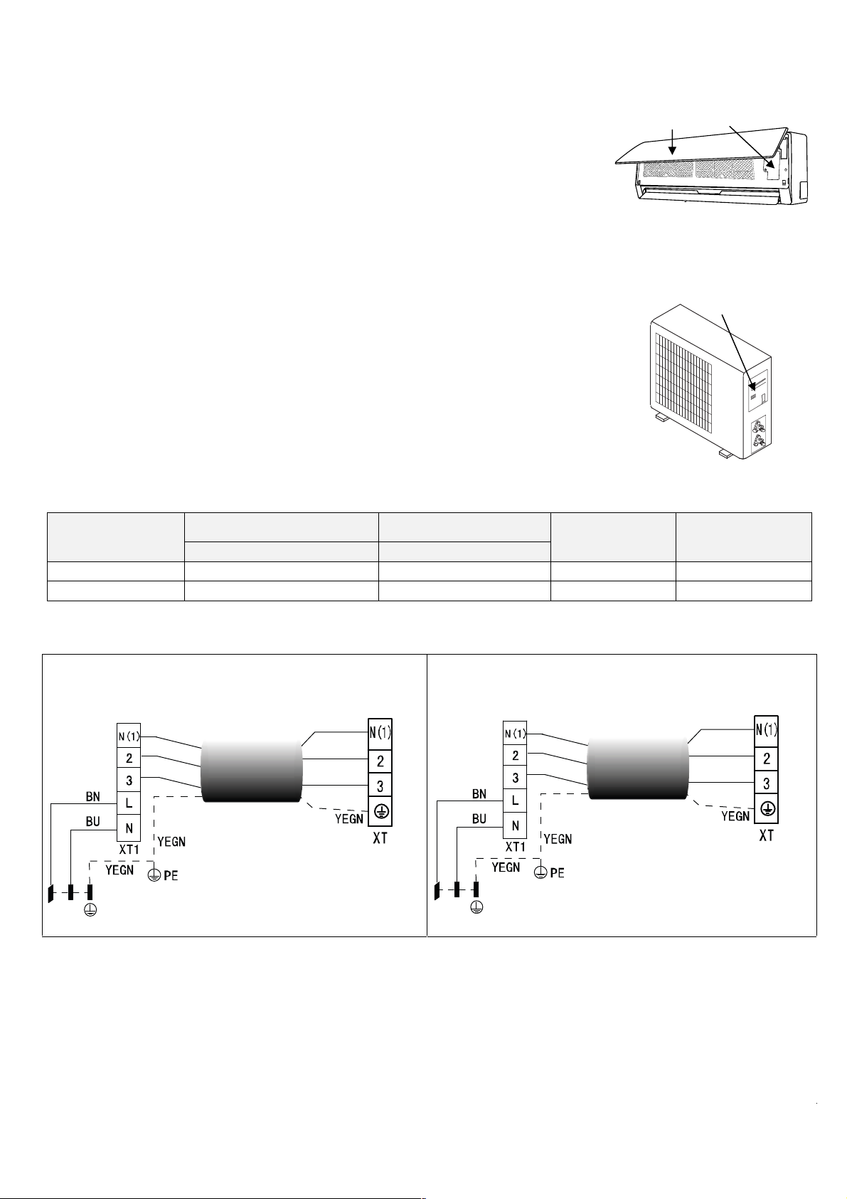
Conexiones electricas
T
T
T
T
Conecte el cable a la unidad interior
Panel Cables de conexiòn
1. El cable de conexión interior-exterior debe ser del tipo H07RN-F.
2. Levante el panel de la unidad interior y retire el tomillo; a continuación retire la tapa
de la ventanila.
3. Conectar la alimentación a la unidad externa con un cabel de tipo H07RN-F.
4. Conecte los cables a los terminales de acuerdo con sus marcas.
UNIDAD INTERIOR
5. Cubra los cables que no se conecten con cinta aislante, de forma que no toquen
ningún componen
Conecte el cable a la unidad exterior
Cubierta
1. Retire la tapa de los componentes eléctricos de la unidad exterior.
2. Conecte los cables a los terminales siguiendo los números de identificación de los
bloques de termi nales interior y exterior.
3. Para impedir que entre agua, forme un bucle descendente con el cable, como ilustra
el diagrama de instalación de las unidades interior y exterior.
4. Aisle los cables no utilizados (conductores) con cinta de PVC. Dispóngalos de forma
que no toquen ningún componente eléctrico o metálico.
UNIDAD EXTERIOR
Especicaciones de los cables
Modelos (W)
1 x 1 DC INVERTER
Cable de conexión de la
alimentación
Sección Sección
2600 W, 3500 W 3 x 1.5 mm² 4 x 0,75 mm² a la unidad exterior 20 A (240V)
5300 W, 7000 W 3 x 1.5 mm² 4 x 0,75 mm² a la unidad exterior 25 A (240V)
Cable de conexión unidades
interior y exterior
alimentación a
Capacidad de
interruptor del circuito
(A)
Conexiones electricas
1 x 1 DC INVERTER (Mod. 2600 W, 3500 W) 1 x 1 DC INVERTER (Mod. 5300 W, 7000 W)
ERMINAL DE LA
UNIDAD EXTERIOR
BU
BK
BN
ALIMENTACIÓN
L N
UNIDAD EXTERIOR
L N
ERMINAL DE LA
BU
BK
BN
ALIMENTACIÓN
ERMINAL DE LA
UNIDAD INTERIOR
BU
BK
BN
ERMINAL DE LA
UNIDAD INTERIOR
BU
BK
BN
14

Conexion de las tuberias
1. Abocardados
La principal causa de fuga de refrigerante es un abocardado defectuoso.
Efectúe correctamente el abocardado siguiendo el procedimiento siguiente.
A: Corte los tubos y el cable.
1. Utilizar tubos con medidas adecuadas a la unidad instalada.
2. Mida la distancia entre las unidades interior y exterior.
3. Corte las tuberías un poco más largas de la distancia medida.
4. Corte un trozo de cable 1,5 m más largo que el tubo.
B: Eliminación de las rebabas
1. Elimine totalmente todas las rebabas del corte de los tubos.
2. Mantenga el tubo de cobre boca abajo mientras elimina las rebabas para que no
caigan en su interior.
C: Colocación de las tuercas
Retire las tuercas para uniones abocardadas de las unidades interior y exterior y
ensártelas en la tubería cuando termine de eliminar las rebabas (no es posible
montarlas después del abocardado).
D: Abocardado
Sujete firmemente la tubería de cobre en una terraja de las dimensiones indicdas en
la tabla siguiente.
Diam. Est (mm)
Φ 6,35
Φ 9,52
Φ 12,7
Φ 16
Apriete de la conexión
● Alinee los centros de los tubos.
● Apriete la tuerca con los dedos todo lo que pueda y luego siga con una llave fija y
una dinamométrica, como ilustra la figura.
IMPORTANTE
● Un par de apriete excesivo puede romper la tuerca en determinadas condiciones
de la instalación.
A(mm)
Max. Min.
1,3
1,6
1,8
2
0,7
1
1
1
Diam. Est.(mm) Par de apriete (N.m)
Φ 6,35
Φ 9,52
Φ 12,7
Φ 16
15 ~ 20
31 ~ 35
50 ~ 55
60 ~ 65
Tubo
15

Purga de aire
La acumulación de aire y humedad en el sistema de refrigeración provoca los
siguientes efectos perjudiciales:
● Aumenta la presión del sistema.
● Aumenta el consumo eléctrico.
● Reduce el rendimiento de la refrigeración o la calefacción.
● El agua presente en el circuito de refrigerante puede congelarse y obstruir los
tubos capilares.
● El agua puede producir corrosión de los componentes del sistema de refrigera
ción. Por tanto, hay que comprobar la presencia de fugas en la unidad interior y en
los tubos que la conectan con la unidad exterior y eliminar del sistema los gases no
condensables y la humedad. Purga del aire con bomba de vacío
● Preparación
Compruebe que se han conectado todos los tubos (tanto de líquido como de gas)
entre las unidades interior y exterior, y que se han terminado las conexiones
eléctricas para efectuar la prueba. Retire las tapas de las válvulas de servicio de los
lados de gas y líquido de la unidad exterior. Observe que esas válvulas de la unidad
exterior están cerradas en esta etapa.
● Longitud del tubo y cantidad de refrigerante:
● Si cambia de sitio la unidad, vacíela con una bomba de vacío.
● Asegúrese de que el refrigerante añadido al acondicionador está siempre en
estado líquido.
Precauciones para manipular la válvula de servicio
● Abra el vastago de la válvula hasta que tropiece con el tope. No trate de abrirlo
más.
● Apriete firmemente el capuchón del vastago con una llave o similar.
● Apriete el tapón del vastago con una llave dinamométrica (vea la tabla de pares
de apriete en la página anterior).
Uso de la bomba de vacío
(Consulte el manejo de la válvula del colector en el manual correspondiente.)
1. Apriete a fondo las tuercas para unión abocardada A, B, C, D, conecte el
latiguillo de baja presión de los manómetros a la toma de presión de la válvula de
servicio en la línea de gas.
2. Conecte el latiguillo a la bomba de vacío.
3. Abra del todo la válvula de baja del manómetro.
4. Ponga en marcha la bomba de vacío, afloje ligeramente la tuerca para unión
abocardada de la válvula de baja del lado del tubo de gas y compruebe que entra
aire (el ruido de funcionamiento de la bomba de vacío cambia y el manómetro
indica O en vez de negativo).
5. Una vez completo el vacio, cierre del todo la válvula de baja de los manómetros y
pare la bomba, Haga un vacio de 15 minutos o más, y compruebe que el
manovacuómetro indica -76cmHg. (-1x10⁵Pa).
6. Gire el vastago de la válvula de servicio B unos 45° en sentido contrario a las
agujas del reloj durante 6-7 segundos después de que el gas haya salido y luego
apriete de nuevo la tuerca. Asegúrese de que el manovacuómetro indica una
presión ligeramente mayor que la atmosférica.
Unidad exterior
Valvula m anometro
Indicador de
presion
Válvula manómetro
Indicador de
Indicatore di pressione
presion
Abierta
tablero de bornes
Válvula de 2 vías
abierta
Válvula de 3 vías
cerrada
Unidad interior
Tubo fle xible
de cargo
Bombona gas
nitrógeno (en
posición vertical)
Unidad interior
Unidad exterior
Cerrada
Bomba de vacìo
Lado liquìdo
llave hexagonal
tapón de drenaje
tapa de
control
Lado gas
capuchón
16

7. Retire el latiguillo de carga del latiguillo de carga de presión baja.
8. Abra del todo los vastagos de las válvulas de servicio B y A.
9. Apriete a fondo el tapón de la válvula de servicio.
9. PRUEBA DE FUNCIONAMIENTO
Realizar la prueba sólo después la acabada de la instalación. Controlar los puntos siguientes antes de realizar la prueba:
Unidad interior y exterior instaladas correctamente;
Tuberías y cables eléctricos conectados correctamente;
Prueba de presión de las tuberías realizada;
La descarga agua de condensación funciona correctamente;
El aislamiento térmico ha sido realizado correctamente;
La puesta a tierra ha sido realizada correctamente;
La longitud de las tuberías y la carga del refrigerante han sido controladas;
La tensión de alimentación corresponde a la tensión del proyecto para el acondicionador;
Las entrada y las salidas del aire de las unidades interioras y exterioras no están obstruidas;
Las válvulas lado gas y lado líquido están abiertas;
El acondicionador ha sido pre-calentado por medio de la tensión.
♦ Prueba:
Seleccionar por medio del mando a distancia el acondicionador en modo refrigeración y controlar los siguientes puntos
como indicado en la sección utilización de este manual. Si unos mal funcionamientos se producen, soluccionarlos por
medio de las instrucciones del capitulo “MALFUNCIONAMIENTOS” de este manual.
1) Unidad interior
a) Controlar si encendido y apagamiento por medio del mando a distancia ocurren correctamente;
b) Controlar si los botones del mando remoto están todos operativos;
c) Controlar si las aletas o los deflectores se mueven correctamente;
d) Controlar si la temperatura interior seleccionada es correcta;
e) Controlar el funcionamiento de los indicadores en el receptor;
f) Controlar el funcionamiento correcto del botón manual;
g) Controlar el funcionamiento correcto del tubo desagüe;
h) Controlar si hay vibraciones o ruidos anormales durante el funcionamiento;
j) Controlar si la capacidad de calefacción es adecuada.
2) Unidad exterior
a) Controlar si hay vibraciones o ruidos anormales durante el funcionamiento;
b) Controlar si hay perdidas de gas refrigerante.
CUIDADO!
17
La función de protección del acondicionador impide el encendido inmediato después de su apagamiento.
Después de la intervención de la protección, se puede volver a poner en marcha el acondicionador
después de 3 minutos desde su último apagamiento.

DE
BEDIENUNGSANLEITUNG
Klimaanlage Split
Winner Series
MODELLE
Für den ordnungsgemäßen Betrieb , lesen Sie und halten Sie diese
Anleitung sorgfältig durch .
Entworfen von Cooper & Hunter International Corporation , Oregon, USA
www.cooperandhunter.com
:
CH-S09FTX5
CH-S12FTX5
CH-S18FTX5
CH-S24FTX5

INHALTSVERZEICHNIS
1. WICHTIGE HINWEISE . ...................................................................................................................................... 1
2. BESTANDTEILE . ................................................................................................................................................
3. DISPLAY . . .......................................................................................................................................................... 2
4. FERNBEDIENUNG . ............................................................................................................................................ 3
4.1. Beschreibung Der Fernbedienungstasten . . .....................................................................................................
4.2. Display Indikatoren Beschreibung . . .................................................................................................................
4.3. Batterien Einsetzung . .......................................................................................................................................
4.4 FERNBEDIENUNG BENUTZUNG . ...................................................................................................................
4.5. manueller Betrieb . ............................................................................................................................................
5. WARTUNG . .......................................................................................................................................................
6. OPERATIONEN UND LEISTUNGEN . ...............................................................................................................
7. FEHLER UND LÖSUNGSVOSCHLAGE . . .......................................................................................................
8. INSTALLATION . ...............................................................................................................................................
9. BETRIEBSTEST . ..............................................................................................................................................
2
3
3
4
4
6
7
8
10
11
17

1. WICHTIGE HINWEISE
s
m
VORSCHRIFT: GEFAHR:
Stromschlag aufgrund unter Spannung stehender Teile.
Keine Arbeiten ausführen, für die das Gerätgeöffnet
werden müsste.
Keine Arbeiten ausführen, für die das Gerät aus der
installierten Anlage entfernt werden müsste.
Das Gerät nicht durch Herausziehen bzw. Einstecken
des Netzsteckers ein- oder ausschalten.
Das Versorgungskabel darf nicht beschädigt werden.
Keine Gegenstände auf dem Gerät liegen lassen.
Nicht auf das Gerät steigen. Personenschäden durch Fallen bzw. Kippen des Gerätes.
Personenschäden durch Verbrennungen aufgrund
vorhandener heißer Teile, oder Verletzungen durch
scharfe Kanten und spitze Teile.
Stromschlag aufgrund unter Spannung stehender Teile.
Personenschäden,Verbrennungen
durch Kälte aufgrund de
aus den abgenommenen Rohren austretenden Gases.
Stromschlag durch Beschädigung des Kabels, des
Steckers oder der Steckdose.
Stromschlag aufgrund freiliegender, unter Spannung
stehender Drähte.
Personenschäden durch Herunterfallen des Gegenstandes
in Folge von Vibrationen.
Nicht auf Stühle, Hocker, Leitern oder nichstandfeste
Unterlagen steigen, um das Gerät zu reinigen.
Personenschäden durch Herunterfallen oder Schnitt- und
Quetschwunden (Leichtmetallleitern).
Gerät vor der Reinigung stets ausschalten, den
Stecker ziehen oder den entsprechenden Schalter
Stromschlag aufgrund unter Spannung stehender Teile.
ausschalten.
Das Gerät darf nicht von Kindern oder unerfahrenen
Personen bedient werden.
Den Luftstrom nicht in Richtung von Kochfeldern oder
Gasherden leiten.
Nicht die Finger in die Luftausgang düsender in die
Luftansauggitter stecken.
Beschädigung des Gerätes durch unsachgemäßen Einsatz.
Explosionen, Brand oder Vergiftungen durch das aus den
Zufuhrdüsender durch den Luftzug gelöschten Flammen
austretende Gas.
Stromschlag aufgrund unter Spannung stehender Teile.
Personenschäden durch Schnittwunden.
Nicht das Kondenswasser trinken. Personenschäden durch Vergiftung.
Bei Brandgeruch oder Rauchaustritt aus dem Gerät ist
umgehend
die Stromzufuhr auszuschalten; daraufhin
das Fenster öffnen und den Kundendienst anfordern.
Keine Arbeiten ausführen, für die das Gerät aus der
installierten Anlage entfernt werden müsste.
Personenschäden durch Verbrennungen oder
Rauchvergiftung.
Überschwemmung durch das aus den abgenommenen
Rohren auslaufende Wasser.
Beschädigung des Gerätes oder der darunter stehenden
Keine Gegenstände auf dem Gerät liegen lassen.
Gegenstände durch das aus seiner Befestigung
ausgebrochene, herunterfallende Gerät.
Zur Reinigung des Gerätes keine Insektiziden,
Lösung oder scharfe Reinigungsmittel verwenden.
Das Gerät nicht für Zwecke verwenden, die von eine
normalen, privaten Haushaltsgebrauch abweichen.
Das Gerät darf nicht von Kindern oder unerfahrenen
Personen bedient werden.
Den Luftstrom nicht in Richtung von wertvollen
Gegenständen, Pflanzen oder Tieren leiten.
Das Klimagerät nicht für längere Zeit unter
Feuchtigkeits- Bedingungen von mehr als 80%
einsetzen.
Beschädigung der Kunststoff- oder Lackteile.
Beschädigung des Gerätes durch Betriebsüberbelastung
Beschädigung der unsachgemäß behandelten Teile.
Beschädigung des Gerätes durch unsachgemäßen
Einsatz.
Beschädigung bzw. Verkümmerung durch zu hohe Kälte /
Hitze, Feuchtigkeit, Zugluft.
Beschädigung der Gegenstände durch Tropfen erhöhter
Kondenswasser Bildung.
1
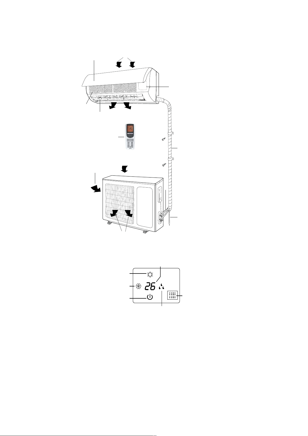
2. BESTANDTEILE
1
(6)
(2)
INNENGERÄT
(5)
(12 )
(11)
(4)
(
)
(3)
(1) Lufteinlass
(2) Vorderabdeckung
(3) Manuelle Einstellung
(4) Luftauslass
(5) Lüftungsgitter
(6) Luftfilter
(8)
(7) Lufteinlass
(8) Verbindungsrohre
(9) Drainagerohr
(10) Luftauslass
(7)
(11) Lufteinlass
(12) Fernbedienung
(10)
AUSSENGERÄT
3. DISPLAY
(5)
(3)
(4)
(2)
(6)
(1) LED Signal-Empfänger
(2) Betrieb Signal
Dies Signal blinkt während die Zündung des Geräts.
(3) Heizung Signal
Diese Signal leuchtet während die Arbeitsweise in der Heizungsart.
(4) Kühlung Signal
Diese Signal leuchtet während die Arbeitsweise in der Kühls Art.
(5) Einstellungstemperatursignal
Es zeigt die Einstellung Temperatur während der Betrieb des Gerät.
(6) Entfeuchtung Indikator
Es leuchtet während die Arbeitsweise in der Entfeuchtungsart.
(9)
(1)
2

4. FERNBEDIENUNG
4.1. Beschreibung Der Fernbedienungstasten
① Taste: drücken Sie diese Taste, um die Klimaanlage einzuschalten/auszuschalten.
② MODE Taste, um die folgenden Betriebsarten einzustellen: : vollkommen automatischer
Betrieb; , Kühlfunktion , Entfeuchtung
③ FAN Taste, um die Lüfters Geschwindigkeit einzustellen: Auto, Niedrige ( ), Niedrige –
Mittlere ( ), Mittlere ( ), Mittlere – Hohe (
Auto
④ TURBO Taste, um die schnelle Kühlung/Heizung einzuschalten/auszuschalten.
⑤ Die "▲" und "▼" Tasten erlauben die Einstellung der Innenraumtemperatur und der
Zeitschaltuhr: "▲" um den Wert zu erhöhen, "▼" um den Wert zu vermindern.
⑥
Taste, um die automatische Bewegung der Leitbleche einzuschalten/auszuschalten.
SLEEP Taste, um die Sleep (Schlaf) Funktion einzuschalten/auszuschalten,
⑦
unabhängig von der Betriebsart der Klimaanlage.
⑧ IFEEL Taste, um die IFEEL Funktion einzuschalten/auszuschalten.
⑨ TIMER ON/TIMER OFF Tasten, um automatisch die Zündung/Abschaltung Zeit der
Klimaanlage einzustellen.
CLOCK Taste, um die Zeit einzustellen.
⑩
⑪ X-FAN Taste, um den innen Lüfter einzuschalten/auszuschalten; diese Funktion wird
benutzt, um die Bauelementen der Inneneinheit zu trocken.
⑫ LIGHT Taste, um das Display der Einheit einzuschalten/auszuschalten.
⑬ / Taste, um die Luftreinigung/Luftstrom Funktion einzustellen ( nicht
verfügbar).
⑭ TEMP Taste, um auf dem Display die gewählte Temperatur oder die Raumtemperatur
anzuzeigen.
, Heizfunktion , nur Lüftungsbetrieb .
), Hohe ( ):
1
2
6
13
14
10
4
5
3
8
7
9
11
12
4.2. Display Indikatoren Beschreibung
: AUTO Modus Indikator
: KÜHLUNG Modus Indikator
: ENTFEUCHTUNG Modus Indikator
: LÜFTUNG Modus Indikator
: HEIZUNG Modus Indikator
: SLEEP Modus Indikator
: CLOCK Indikator
H
U
R
O
N
O
O
-
F
F
: TIMER Indikator
: TEMPERATUR Indikator
: X-FAN Modus Indikator
: LÜFTREINIGUNG Modus Indikator
: QUIET Modus Indikator (nicht verfügbar)
: 8°C Heizung Funktion Indikator
: LÜFTWECHSEL Modus Indikator (nicht verfügbar)
: LIGHT Indikator
: LOCK Indikator
: Up & Down-Swing-Anzeige
: links und rechts schwingen Anzeige (nicht verfügbar)
: TURBO Modus Indikator
3
DISPLAY
U
A
T
O
F
A
N
AUT
O
$
88
6
O
P
E
R
°
F
°
C
H
O
U
R
N
O
O
-
F
F

: SIGNALÜBERTRAGUNG LED
F
: I FEEL Modus Indikator
FAN : LÜFTERSGESCHWINDIGKEIT Indikator
: EINSTELLUNG TEMPERATUR Indikator
4.3. Batterien Einsetzung
Benutzen Sie zwei AAA Modell Alkalien-Batterien.
① Nehmen Sie den Deckel der Batterien. Nehmen Sie die alten Batterien, und setzen.
② und ③ Sie die neuen Batterien ein (achtgeben Sie auf die „+“ und „-“ Polarität).
2
④ Stellen Sie den Deckel der Batterien wieder.
1
VERMERK:
♦ Mischen Sie nicht neue und alte Batterien ab: das könnte Betriebsstörungen verursachen.
3
♦ Falls die Fernbedienung für eine lange Zeit nicht verwendet wird, sollen die Batterien
entfernt werden, um Schaden, wegen eventuellen chemischen Austritte, zu vermeiden.
♦ Wenn das Tonsignal der Inneneinheit nicht mehr empfangen wird oder der Übertragung
Anzeiger auf der Fernbedienung nicht erleuchtet wird, sollen die Batterien ersetzt werden.
4
♦ Stecken Sie die Fernbedienung in den dafür vorgesehenen Halter ein, der an die Wand
befestigt wird (um eine korrekte Signalübertragung zu gewährleisten).
4.4 FERNBEDIENUNG BENUTZUNG
● EINHEIT ZÜNDUNG/ABSCHALTUNG
Drücken Sie die Taste, um die Einheit einzuschalten/auszuschalten.
● BETRIEBSART EINSTELLUNG
Drücken Sie öfter die MODE Taste, um die Betriebsart der Einheit zu ändern. Die gewählte Betriebsart wird auf dem Display
angezeigt:
→ → → →
: vollkommen automatischer Betrieb;
: Kühlfunktion;
: Entfeuchtung;
: Heizfunktion;
: nur Lüftungsbetrieb.
Mit der Auswahl des AUTO automatischen Programms, kann die Einheit im KÜHLBETRIEB und im HEIZBETRIEB arbeiten,
abhängig vom Temperaturunterschied zwischen der vorhandenen Raumtemperatur und der durch die Fernbedienung
ausgewählten werden wird. Wenn das COOL Kühlprogramm ausgewählt wird, arbeitet die Einheit mit freiem
Temperatursollwert, und verringert die Raumtemperatur. Wenn das DRY Entfeuchtung Programm ausgewählt wird, arbeitet
die Einheit mit freiem Temperatursollwert, und verringert so nach die Raumtemperatur und die Feuchtigkeit im Raum. Im
DRY Entfeuchtung Programm, kann die FAN Taste nicht benutzt werden. Wenn das HEAT Heizprogramm ausgewählt wird,
arbeitet die Einheit mit freiem Temperatursollwert, und erhöht die Raumtemperatur. Wenn das FAN Lüftungsprogramm
ausgewählt wird, arbeitet die Einheit ohne Temperatursollwert, und ventiliert die Raumluft.
Der Ventilator der Einheit hält bei Erreichen des eingestellten Temperaturwerts an, um dann automatisch mit minimaler
Drehzahl wieder zu starten, um die Bildung von Luftschichten in der Nähe des Geräts zu vermeiden.
WICHTIG!
Bei Auswahl der COOL DRY Funktion, könnte der Ventilator nicht sofort starten, da die ANTI-HEATING Funktion
vorhanden ist. Bei Auswahl der HEAT Funktion, könnte der Ventilator nicht sofort starten, da die ANTI-COOLING Funktion
vorhanden ist.
● LEITBLECHE EINSTELLUNG
Um eine optimale Verteilung der Luft zu erreichen, stellen Sie die Position der Leitbleche ein, und achten Sie darauf, dass
der Luftstrom nicht gegen das Volk gerichtet wird. Um die Leitbleche einzuschalten, beachten Sie den folgenden Bildungen:
1) Up & Down-Swing-Funktion
drücken Sie die Taste, um den Schwenkwinkel einzustellen, wie folgt:
OF
4

Vermerk:
diese Fernbedienung ist universale. Wenn der (
Betrieb die Schwingung der Leitbleche als .
SWING
) Befehl am Gerät nicht gesendet wird, setzt es im
zeigt an, dass die Leitbleche als
2) links & rechts Swing-Funktion
arbeitet.
Drücken Taste zum Starten oder Stoppen links & rechts Swing-Funktion. Die Fernbedienung ist standardmäßig einfache
Schaukel Zustand.
OFF
● LÜFTUNG EINSTELLUNG
Drücken Sie öfter die FAN Taste, um die Lüfters Geschwindigkeit (niedrige, mittlere, hohe) einzustellen oder, um die AUTO
Funktion einzuschalten. Die gewählte Betriebsart wird auf dem Display angezeigt:
Auto
Auto, Niedrige ( ), Niedrige – Mittlere ( ), Mittlere ( ), Mittlere – Hohe ( ), Hohe ( ).
● I FEEL FUNKTION EINSTELLUNG
Drücken Sie die IFEEL Taste, um die Funktion einzuschalten. In diesem Fall, reguliert der Einheit automatisch die
Raumtemperatur in Bezug auf die Temperatur, die vom Sensor gemessene wird; der Sensor wird an der Fernbedienung
installiert. Drücken Sie noch mal diese Taste, um die Funktion auszuschalten.
● LÜFTREINIGUNG ( )/LÜFTWECHSEL ( nicht verfügbar) FUNKTION
Drücken Sie die Taste, um diese Funktion einzuschalten/auszuschalten.
Drücken Sie einmal die
Taste, um die Luftwechsel Funktion zu aktivieren: der Display zeigt den “ ” Indikator an.
Drücken Sie nochmal dieselbe Taste, um gleichzeitig die Luftreinigung und die Luftwechsel Funktion zu aktivieren: der
Display zeigt die “ ” und “ ” Indikatoren an. Wenn Sie für das dritten Mal dieselbe Taste drücken, werden diese
Funktionen desaktiviert. Wenn Sie für das vierten Mal dieselbe Taste drücken, wird die Luftreinigung Funktion aktiviert: der
Display zeigt den “ ” Indikator an. Drücken Sie nochmal dieselbe Taste, um die normale Arbeitsweise der Klimaanlage
auszuwählen.
● SLEEP (SCHLAF) MODUS
Die “SLEEP“ Funktion kann für die Heizung oder für die Kühlung verwendet werden.
Diese Funktion sorgt für besseres Komfort beim Schlafen.
Wenn der SLEEP Modus aktiviert ist:
- wird die niedrige Lüfter Geschwindigkeit angesetzt;
- wird die Einstellungstemperatur um 1°C steigen (senkt), wenn die Klimaanlage im Kühlung (Heizung) Mode-Betrieb
arbeitet. Wenn die angestellte Temperatur bei 2°C ändert, halt das Gerät bis der achte Stunde im SLEEP Mode-Betrieb die
Temperatur; danach, es automatisch erlöscht.
● TEMP FUNKTION
Drücken Sie die TEMP Taste, um auf dem Display der Einheit die gewählte Temperatur, die Raumtemperatur und die
Außentemperatur anzuzeigen.
Vermerk: die Außentemperatur wird nur für einengen Modelle angezeigt.
● QUIET FUNKTION (nicht verfügbar)
Drücken Sie diese Taste, um die Auto QUIET Funktion zu aktivieren: der Display zeigt die “Auto” Aufschrift an (in Bezug auf
den Auto Modus), und zeigt das "
wird, verschwindet der
Indikator auf dem Display. Bei der Zündung der Einheit, ist die QUIET OFF Funktion die ab Werk
" Symbol an (in Bezug auf den QUIET Modus). Wenn der QUIET Modus desaktiviert
voreingestellte Funktion.
Vermerk:
die QUIET Funktion wird während der Lüftung oder der Entfeuchtung Arbeitsweise desaktiviert. Die Lüfter
Geschwindigkeit kann nicht geändert werden, wenn die QUIET Funktion aktiviert ist.
● CLOCK (UHRZEIT) Taste
Drücken Sie die CLOCK Taste, um die Zeit einzustellen, durch die “▲” und “▼” Tasten:
- drücken Sie einmal die Tasten, um bei 1 Minute die Zeit zu erhöhen/absenken;
- drücken Sie für 2 Sekunden die Tasten, um bei 10 Minuten die Zeit zu erhöhen/absenken.
● TIMER FUNKTION
- Einstellung der TIMER ON Funktion
Drücken Sie die TIMER-ON Taste, um die Zeitprogrammierung der Klimaanlage einzustellen:
5

1) drücken Sie die TIMER-ON Taste; die Angabe schaltet aus, und die “ON“ Angabe leuchtet auf dem Display; drücken
Sie die “▲” oder “▼” Taste, um die gewünschte Zeit für die eingeplante Anschaltung der Klimaanlage einzustellen;
- drücken Sie einmal die “▲” oder “▼“ Taste, um die Zeit um eine Minute (mehr oder weniger) einzustellen;
- drücken Sie für zwei Minuten die “▲” oder “▼“ Taste, um die Zeit um 10 Minuten zu vermehren oder zu vermindern.
Vermerk: falls die Zeit innerhalb 10 Sekunden, nach die TIMER ON Taste gedrückt wird, nicht eingestellt wird, wird die
Fernbedienung automatisch die Funktion TIMER ON ausschalten.
2) wenn die gewünschte Zeit auf dem Display visualisiert wird, drücken Sie die TIMER ON Taste: ein “Tonsignal“ wird
gehört, die “ON” Indikator leuchtet nicht mehrer auf, und der TIMER Indikator der Inneneinheit leuchtet auf.
3) das Display der Fernbedienung zeigt die aktuelle Zeit nach sofort der Einstellung der TIMER ON Funktion an.
- TIMER ON Auslöschen:
Drücken Sie noch mal die TIMER ON Taste; ein Tonsignal wird gehört, danach verschwindet der Anzeiger, und die TIMER
ON Funktion ausgelöscht wird.
Vermerk: das gilt auch für die Einstellung der TIMER OFF Funktion, um die Klimaanlage auf die eingestellte Uhrzeit
automatisch auszuschalten.
● TURBO FUNKTION
- Die TURBO Funktion wird verwendet, um die schnelle Abkühlung und Heizung auszuschalten.
- In der TURBO Funktion, kann man die Luftrichtung und den Timer regulieren. Um die Funktion TURBO auszulöschen,
drücken Sie die TURBO oder MODE oder FAN oder Taste, und das Display geht wieder auf die ursprüngliche
Arbeitsweise zurück.
● LIGHT (LICHT) FUNKTION
Drücken Sie die
nochmals die Taste, um das Licht auszuschalten: der Indikator verschwindet.
● X-FAN FUNKTION
Wenn die X-FAN Taste während der KÜHLUNG oder der ENTFEUCHTUNG gedrückt wird, visualisiert das Display den
Indikator, und funktioniert der Innenlüfter noch für 10 Minuten, um die Innenseite der Einheit zu trocknen, auch wenn sie
ausgelöschte wird.
Die X-FAN OFF ist die Einstellung ab Werk, während der Zündung. X-FAN funktioniert nicht in der AUTO, LÜFTUNG oder
HEIZUNG Betriebsart.
● LOCK (SPERRE) MODUS
Wenn die “▲” und “▼” Tasten werden zugleich gedrückt, blockiert die Fernbedienung die letzte programmierte Aktion. Alle
Steuerungstasten werden desaktiviert, einschließlich die Taste. Wenn die “▲” und “▼” Tasten werden wieder gedrückt,
werden die Funktionen der Tasten wiederhergestellt.
● °C/°F Funktion: wenn das Gerät ist gelöscht, drücken Sie zugleich die “MODE” und “▼” Tasten um die Temperatur wie
°C oder wie °F zu visualisieren.
● ENERGY SAVING (ENERGIEEINSPARUNG) FUNKTION
Drücken Sie zugleich die "TEMP" und "CLOCK" Tasten, während der Kühlung Arbeitsweise, um diese Funktion zu
aktivieren: der Display zeigt die “SE” Aufschrift an. Drücken Sie nochmal dieselben Tasten, um diese Funktion zu
stornieren.
Taste, um das Licht des Displays einzuschalten: der Indikator wird anzeigt. Drücken Sie
LIGHT
● 8°C (46°F) HEIZUNG FUNKTION
Drücken Sie zugleich die "TEMP" und "CLOCK" Tasten, während der Heizung Arbeitsweise, um diese Funktion zu
aktivieren: der Display zeigt das Symbol an. Drücken Sie noch mal dieselben Tasten, um diese Funktion zu deaktivieren.
4.5. manueller Betrieb
Die Klimaanlage kann manuell geregelt werden (z.B. wenn Sie die Fernbedienung verlegt haben oder wenn die Batterien
ausgetauscht werden müssen).
1. Heben Sie die Vorderabdeckung an und drücken Sie sie nach oben, bis sie einrastet.
2. Drücken Sie den manuellen Steuerknopf, um die Anlage auf Automatikbetrieb zu setzen.
3. Drücken Sie die Vorderabdeckung wieder in die ursprüngliche Position zurück.
Manuelle
Einstellung
ACHTUNG:
● Jedes Mal, wenn Sie den manuellen Steuerknopf drücken, wechselt automatisch der
Betriebsmodus von COOL nach HEAT und FAN Accordin auf Raumtemperatur.
● Drücken Sie die Taste, um den Betrieb der Klimaanlage stoppen.
6

5. WARTUNG
Household
Drain
Clea ner
No
WARNUNG
Vor jeder Reinigung muss die Anlage ausgeschaltet und vom Netz abgezogen werden.
Reinigung des Innengeräts und der Fernbedienung VORSICHTSMASSNAHMEN
Warnungen
● Reinigen Sie das Innengerät und die Fernbedienung mit einem weichen trockenen
Tuch.
● Bei stärkerer Verschmutzung des Innengeräts empfiehlt es sich, das Tuch mit kaltem
Wasser zu befeuchten.
● Die Vorderabdeckung ist abnehmbar und kann unter fließendem Wasser abgespült
werden. Anschließend ist die Abdeckung trocken zu reiben.
● Verwenden Sie keine chemischen Reinigungsmittel oder spezielle Produkte zur
Behandlung staubverschmutzter Oberflächen.
● Das Gerät darf nicht mit Benzin, Benzol, Lösungsmitteln, Scheuermitteln oder
ähnlichen Produkten gereinigt werden. Diese Produkte könnten Kratzer verursachen oder
die Kunststoffflächen verformen.
Reinigung des Luftfilters
Der Luftfilter muss in regelmäßigen Abständen gereinigt werden, da andernfalls die
Leistungsfähigkeit der Anlage beeinträchtigt wird. Reinigen Sie den Filter aller zwei
Wochen.
1. Drücken Sie die Vorderabdeckung des Innengeräts nach oben, bis sie einrastet.
2. Heben Sie den Filter leicht an und nehmen Sie ihn aus dem Filterhalter heraus, indem
Sie ihn nach unten drücken.
3. Nehmen Sie den Filter vollständig aus dem Innengerät heraus
● Reinigen Sie den Filter aller zwei Wochen.
● Verwenden Sie hierzu einen Staubsauger oder spülen Sie ihn mit Wasser ab. Lassen
Sie den Filter an einem gut durchlüfteten Ort trocknen.
4. Nehmen Sie den elektrostatischen Filter wie aus der Abbildung ersichtlich aus dem
Rahmen heraus (nur für Modelle mit elektrostatischem Filter).
Nach dem Öffnen des Filtergitters sollten Sie 10 Minuten warten, bevor Sie den Filter
berühren, da andernfalls die Gefahr eines Stromschlags besteht.
● Säubern Sie den Filter mit einem milden Reinigungsmittel oder mit Wasser und lassen
Sie ihn zwei Stunden in der Sonne trocknen.
● Prüfen Sie den Umlaufstreifen bzw. den Filterrahmen auf Beschädigungen, bevor Sie
den Filter wieder in das Gerät einsetzen.
5. Setzen Sie den gereinigten Filter wieder in den Filterhalter ein.
6. Führen Sie hierzu den oberen Teil des Filters in den Halter ein. Achten Sie darauf,
dass der rechte und linke Rand korrekt ausgerichtet sind.
WARTUNG
Sollten Sie die Anlage längere Zeit nicht benutzen, befolgen Sie bitte die nachstehenden
Anweisungen:
(1) Lassen Sie den Lüfter etwa den einen halben Tag lang laufen, damit das Innengerät
gut getrocknet wird.
(2) Schalten Sie danach die Anlage aus und ziehen Sie sie vom Netz ab. Entfernen Sie
die Batterien aus der Fernbedienung.
(3) Das Außengerät muss regelmäßig gereinigt und gewartet werden. Diese Arbeiten
sollten Sie keineswegs selbständig durchführen. Setzen Sie sich hierfür mit einem
Fachhändler oder dem technischen Kundendienst in Verbindung.
7

Überprüfung vor Inbetriebnahme
● Prüfen Sie die Elektrokabel auf Schäden und vergewissern Sie sich, dass die Kabel ans Netz angeschlossen sind.
● Prüfen Sie, ob der Luftfilter korrekt installiert ist.
● Vergewissern Sie sich, dass der Lufteinlass und der Luftauslass nicht blockiert oder verstopft sind.
VORSICHTSMASSNAHMEN
● Vermeiden Sie eine Berührung der Metallteile beim Filteraustausch. Die scharfen Kanten stellen eine Gefahrenquelle dar
und es könnte zu Verletzungen kommen.
● Reinigen Sie die Anlage niemals mit Wasser. Beim Eintritt von Wasser in die Anlage könnte die Isolierung beschädigt
werden. Außerdem besteht die Gefahr von Stromschlägen.
● Vergewissern Sie sich, dass Leistungs- und Stromschalter ausgeschaltet sind, bevor Sie die Anlage reinigen.
6. OPERATIONEN UND LEISTUNGEN
1. Schutzfunktion Kompressor schütz
● Nach dem Ausschalten der Klimaanlage bleibt der Kompressor 3 Minuten lang inaktiv.
Schutz gegen Kaltluft (nur bei Modellen mit kombiniertem Kühl- und Heizbetrieb)
● Wenn die programmierte Temperatur nicht erreicht wurde und der Wärmetauscher aus den folgenden drei Gründen nicht
in Betrieb ist, wird im Heizmodus keine Kaltluft generiert:
A) Aktivierung des Heizmodus
B) Aktivierung des Enteisungsmodus
C) Aktivierung des Heizmodus bei niedrigen Temperaturen.
● Im Enteisungsmodus sind der Lüfter des Innen- und des Außengeräts nicht in Betrieb (nur bei Modellen mit Heiz- und
Kühlfunktion).
Enteisung (nur bei Modellen mit Heiz- und Kühlfunktion)
● Bei niedrigen Außentemperaturen und hoher Luftfeuchte kann es im Heizbetrieb zu Frostbildung am Außengerät
kommen, so dass die Leistung der Anlage im Heizmodus etwas gemindert wird.
● Bei Frostbildung wird der Heizmodus automatisch eingestellt und die Enteisungsfunktion wird aktiviert.
● Je nach Außentemperatur und Frostanteil kann die Dauer des Enteisungsvorgangs zwischen 4 und 10 Minuten betragen.
2. Dampfabsonderung am Innengerät
● Bei hohem Temperaturunterschied zwischen der Temperatur des eintretenden und des austretenden Luftstroms und
gleichzeitig hoher Raumluftfeuchte kommt es im Kühlbetrieb zur Dampfabsonderung am Innengerät.
● Wenn die Luftfeuchte im Zuge des Enteisungsvorgangs ansteigt, können bei nachfolgender. Umstellung auf den
Heizmodus ebenso Dämpfe entstehen.
3. Betriebsgeräusche
● Während des Betriebs der Anlage und beim Ausschalten kann es zu leisen Geräuschen kommen. Diese entstehen durch
den Zyklus des Kühlwassers.
● Außerdem ist während des Betriebs der Anlage und beim Ausschalten ein leises Knacken zu hören, da sich die
Kunststoffbauteile durch den Heizvorgang ausdehnen und bei abnehmender Wärme wieder zusammenziehen.
● Ein weiteres Betriebsgeräusch entsteht, wenn das Gebläse beim Einschalten der Anlage in die ursprüngliche Position
zurück bewegt wird.
4. Staubbildung am Innengerät
Wenn die Anlage längere Zeit nicht genutzt wurde, können beim Einschalten geringe Staubmengen auftreten.
5. Geruchsbildung am Innengerät
Auf Grund der Temperaturänderung an den Bauteilen der Anlage und den Einrichtungsgegenständen sowie auf Grund der
Dampfbildung können eventuell Gerüche auftreten.
6. Die Anlage kann vom Heiz- und Kühlmodus automatisch auf den Lüftungsmodus umstellen (nur bei Geräten mit
kombinierter Heiz- und Kühlfunktion).
8

Bei Erreichen der programmierten Raumtemperatur wird der Kompressor automatisch deaktiviert und die Anlage schaltet
auf den exklusiven Lüftungsmodus um (FAN ONLY). Bei Absinken der Raumtemperatur im Heizbetrieb bzw. beim Anstieg
der Raumtemperatur im Kühlberieb wird der Kompressor automatisch wieder zugeschaltet (nur bei Modellen mit
kombinierter Heiz- und Kühlfunktion).
7. Bei hoher Raumluftfeuchte (über 80%) kann im Kühlbetrieb Wasser aus dem Innengerät austreten
Richten Sie das horizontale Lüftungsgitter auf den höchstmöglichen Öffnungsgrad aus und stellen Sie den Lüfter auf
Höchstgeschwindigkeit.
8. Heizmodus (nur bei Modellen mit kombinierter Kühl- und Heizfunktion)
Bei Aktivierung des Heizmodus wird Warmluft aus dem Außengerät bezogen und über das Innengerät abgegeben.
Demzufolge ist die Heizleistung der Klimaanlage bei sinkenden Außentemperaturen gemindert. Bei hohem
Temperaturunterschied zwischen
Außentemperatur und Raumtemperatur wird die Heizleistung der Anlage stark belastet. Sollte sich in diesem Falle die
Heizleistung als nicht ausreichend erweisen, empfehlen wir Ihnen die Anschaffung eines zusätzlichen Heizgeräts.
9. Automatische Neueinschaltfunktion
Bei Stromausfall schaltet die Klimaanlage automatisch ab. Bei Modellen ohne automatische Neueinschaltfunktion beginnt
die Betriebsanzeige bei erneuter Stromzufuhr zu blinken. Drücken Sie in diesem Falle die -Taste der Fernbedienung, um
die Anlage erneut in Betrieb zu setzen. Bei Modellen mit automatischer Neueinschaltfunktion schaltet sich die Anlage
automatisch wieder ein. Dabei bleiben alle zuvor programmierten Einstellungen erhalten.
10. Die Leistung der Klimaanlage kann durch Strahlung (insbesondere Handystrahlung)
beeinträchtigt werden. Ist dies der Fall, empfehlen wir Ihnen, die Anlage aus- und unmittelbar danach wieder einzuschalten.
Drücken Sie hierzu die -Taste der Fernbedienung.
9

7. FEHLER UND LÖSUNGSVOSCHLAGE
Bei Auftreten einer der nachstehend aufgeführten Fälle muss die Anlage unverzüglich ausgeschaltet werden. Ziehen Sie
die Anlage vom Stromversorgungsnetz ab und setzen Sie sich mit dem technischen Kundendienst in Verbindung
Die Betriebsanzeige oder eine andere Anzeige blinkt mehrmals hintereinander auf (5 mal pro
Sekunde) und das Problem kann nicht durch Ein-und Ausschalten der Anlage behoben werden.
Trouble
Fehler Ursache Behebung
Die Anlage schaltet sich
nicht ein.
Das Innengerät
funktioniert, doch die Heizund Kühlleistung der
Anlage ist nicht
zufriedenstellend (nur bei
Modellen mit kombinierter
Heiz- und Kühlfunktion)
Es ist Wasser in die Anlage eingetreten oder es befinden sich Fremdkörper im Gerät.
Die Sicherung ist durchgebrannt oder der Leistungsschalter sich häufig aus.
Die Fernbedienung funktioniert nicht oder fällt häufig aus.
Sonstige Fehler.
Stromausfall
Die Anlage ist nicht an das
Stromversorgungsnetz angeschlossen.
Warten Sie, bis die Stromzufuhr erneut
gewährleistet ist.
Vergewissern Sie sich, dass der Stecker des
Netzkabels korrekt angeschlossen
Die Sicherung ist durchgebrannt. Tauschen Sie die Sicherung aus.
Die Batterien der Fernbedienung müssen
ausgetauscht werden.
Die Einschaltzeit wurde nicht korrekt
programmiert.
Die programmierte Temperatur ist
unzureichend.
Tauschen Sie die Batterien aus.
Warten Sie, bis sich die Anlage einschaltet oder
korrigieren Sie die programmierten Zeiten
Stellen Sie eine höhere oder niedrigere
Temperatur ein.
Der Luftfilter muss gereinigt werden. Reinigen Sie den Luftfilter.
Die Anlage wird bei geöffneten Türen und
Fenstern betrieben.
Die Anlage wird bei geöffneten Türen und
Fenster. betrieben
Die Schutz Funktion des Kompressors
wurde aktiviert (3-minütige Pause).
Schließen Sie Türen und Fenster.
Schließen Sie Türen und Fenster.
Warten Sie, bis sich der Kompressor wieder
zuschaltet.
Sollten die genannten Fehler nicht behüten werden können, setzen Sie sich bitte mit Ihrem Fachhändler oder mit dem
technischen Kundendienst in Verbindung. Beschreiben Sie die auftretenden Feher so genau wie möglich und halten Sie die
Angaben zu Ihrem konkreten Modell bereit.
Anmerkung:
Versuchen Sie keinesfalls, die Anlage selbständig zu reparieren. Setzen Sie sich unverzüglich mit dem zugelassenen
technischen Kundendienst in Verbindung.
10

8. INSTALLATION
Innengerät
● Setzten Sie das Innengerät weder Hitze noch Wasserdampf aus.
● Wählen Sie einen Platz, an dem sich keine Hindernisse vor oder um das Gerät befinden.
● Achten Sie darauf, dass das Kondenswasser gut abgeleitet werden kann.
● Nicht in der Nähe eines Eingangs installieren.
● Sorgen Sie dafür, dass links und rechts vom Gerät mehr als 12 cm Platz frei ist.
● Nutzen Sie einen Metalldetektor, um eventuelle Metalle aufzuspüren. Andernfalls könnte die Wand beschädigt werden.
● Für eine möglichst gute Dämpfung der Vibration und der Geräusche ist ein Rohr lauf von mindestens 3 m erforderlich.
● Das Innengerät sollte mindestens 2,3 m über dem Boden installiert werden.
● Das Innengerät sollte so installiert werden, dass mindestens 15 cm Platz bis zur Decke sind.
● Bei Veränderungen der Rohrlänge muss ggf. die Kühlmittelmenge entsprechend abgestimmt werden
60 cm
≤
m
≤ 15 cm
m
c
5
1
m
c
15
≤
cm
2
0
5
2
≤
≤
≤
60 cm
5
0
≤
0
2
m
c
0
c
5
1
≤
≤ 15 cm
Außengerät
● Wenn über der Tür nach außen eine Markise angebracht i oder Regen zu vermeiden, sorgen Sie dafür, dass die
Absbehindert wird.
● Achten Sie darauf, dass hinter Gerät und links vom Gerät jeweils mehr als 30 cm Platz frei ist. Vor dem Gerät sollten mehr
als 200 cm Platz sein, und an der Anschlussseite (rechts) mehr als 60 cm.
● Achten Sie darauf, dass sich keine Tiere oder Pflanzen am Lufteinzug oder- auslasse befinden.
● Bedenken Sie das Gewicht der Klimaanlage und wählen Sie einen Ort, der weder
Geräusch noch vibrationsempfindlich ist.
● Wählen Sie den Platz so, dass die warme Luft und die Geräusche der Klimaanlage die Nachbarn nicht stören.
● Installieren Sie das Außengerät auf einer festen Unterlage, um starken Lärm und Vibrationen zu vermeiden.
● Orientieren Sie das Abluftgebläse so, dass der Luftstrom nicht behindert wird.
● Falls der Installationsort starkem Wind ausgesetzt ist, wie z.B. am Meer, sorgen Sie dafür, dass der Ventilator richtig
funktioniert, indem Sie das Gerät längs entlang der Mauer aufstellen oder Windleitbleche nutzen.
● Stellen Sie das Gerät insbesondere in windigen Gegenden so auf, dass es möglichst wenig Wind abbekommt.
● Wenn das Gerät aufgehängt werden soll, muss die Montagestütze die entsprechenden Übersicht angegebenen
technischen Anforderungen erfüllen. Die Installationswand sollte aus festen Ziegeln, Beton oder einem vergleichbaren
Baumaterial bestehen. Andernfalls muss die Wand verstärkt werden. Die Verbindung zwischen Stütze und Wand und
zwischen Stütze und Klimaanlage muss fest, stabil und zuverlässig sein.
● Stellen Sie sicher, dass der Luftstrom nicht blockiert wird.
.
Installation auf dem Dach:
● Wenn das Außengerät auf einem Dach installiert wird, achten Sie darauf, dass es eben steht. Sorgen Sie dafür, dass die
Dachträger und die Befestigungsmethode für den Ort des Gerätes angemessen sind.
11

● Halten Sie die lokalen Vorschriften zur Anbringung von Geräten auf Dachflächen ein.
● Wenn das Außengerät auf einem Dach oder an einer Außenwand installiert wird, kann dies zu viele Geräusche und
Vibrationen hervorrufen. Zudem wird die Wartung erschwert.
1. Bringen Sie die Montageplatte an.
1. Bringen Sie die Montageplatte horizontal an tragenden Teilen der Wand an, so dass genügend Platz um die Platte
herum frei bleibt.
2. Wenn die Wand aus Ziegeln, Beton o.a. Material besteht, bohren Sie 5 Löcher mit einem Durchmesser von 5 mm in die
Wand. Fügen Sie die Befestigungsdübel für die entsprechenden Einbauschrauben ein.
3. Befestigen Sie die Montageplatte mit 5 Schrauben vom Typ "ST4.2X25TA" an der Wand.
Mod. 2600 W, 3500 W
Mod. 5300 W
Mauer
Raum
der
oben
Mauer
Left
Mark in der Mitte
Pegelmesser
(Rückseite des Rohrloch)
Mauer
Raum
der
oben
Mauer
Right
Mauer
Raum
der
oben
Mauer
Left
Mark in der Mitte
Pegelmesser
(Rückseite des Rohrloch)
Mauer
Raum
der
oben
Mauer
Right
Mod. 7000 W
Mauer
Raum
der
oben
Mauer
Mark in der Mitte
Left
(Rückseite des Rohrloch)
Pegelmesser
(Rückseite des Rohrloch)
Raum
der
oben
Mauer
Right
Mauer
2. Bohren Sie ein Loch in die Wand.
1. Legen Sie die Lochpositionen nach dem Schaubild in Abb. 5 fest. Bohren Sie ein (1) Loch (diamter ist in der
Montageplatte gesehen), das leicht nach außen geneigt ist.
2. Nutzen Sie stets einen Führungskanal, wenn Sie Metallgitter, Metallplatten o.a. durchbohren.
3. Installation des Anschlußrohrs und des Drainageschlauchs
Drainageschlauch
1. Verlegen Sie den Drainageschlauch so, dass er nach unten hängt. Installieren Sie den Schlauch keinesfalls wie unten
dargestellt.
2. Wenn Sie einen Verlängerungsschlauch anbringen, isolieren Sie den Anschluss der Verlängerung mit einer Schutzhülse
und lassen Sie den Drainageschlauch nicht durchhängen.
Anschlußrohr
1. Entfernen Sie die rechte oder linke Abdeckung von der Seitenwand, je nachdem, ob das Rohr rechts oder links
angeschlossen werden soll.
● Erklären Sie den Kunden, dass die Rohrabdeckung aufbewahrt werden sollte, für den Fall, dass die Klimaanlage einmal
an einem anderen Ort angebracht wird.
2. Für den Anschluß des Rohrs hinten rechts oder hinten links, gehen Sie wie in der Abbildung dargestellt vor. Knicken Sie
das Anschlußrohr so, dass es maximal 43 mm von der Wand verlegt wird.
3. Befestigen Sie das Ende des Anschlußrohrs. (Für die Befestigung der Verbindung unter KÜHLMITTELROHR
ANSCHLUSS).
12

4. Installation des Innengeräts
1. Führen Sie die Rohrleitungen durch das Loch in der Wand.
2. Hängen Sie die Halteplätze an der Hinterseite des Innengerätes in den oberen Haken der Montageplatte und bewegen
Sie das Innengerät seitwärts, um zu prüfen, ob es sicher ein gehakt ist.
3. Die Rohre lassen sich einfach verlegen, indem man das Innengerät mit dem Polstermaterial, das sich zwischen dem
Gerät und der Wand befindet, anhebt. Entfernen Sie das Material nach dem Verlegen der Rohre.
4. Schieben Sie das Unterteil des Innengeräts an der Wand hoch. Bewegen.
Sie es dann zu den Seiten und nach oben und unten, um zu überprüfen, ob es
sicher festgehakt ist.
5. Rohrverlegung
● Binden Sie die Rohre, das Anschluss Kabel und den Drainageschlauch mit einem Band zusammen, wie in Abb. 10
dargestellt.
● Das an der Rückseite des Innengeräts ablaufende Kondenswasser wird in einem Behälter gesammelt und durch ein Rohr
aus dem Zimmer geleitet. Verwenden Sie diesen Behälter nicht zu anderen Zwecken.
VORSICHT
● Schließen Sie zunächst das Innen- und danach das Außengerät an.
● Lassen Sie die Rohre nicht aus der Hinterseite des Innengerätes
herausragen.
● Achten Sie darauf, dass der Drainageschlauch nicht durchhängt.
● Isolieren Sie beide Hilfsrohre thermisch.
● Achten Sie darauf, dass sich der Drainageschlauch an der
niedrigsten Seite des Bündels befindet. Wenn er sich oben befindet,
Innengerät
l
s
a
G
I
t
i
m
Anschlussdrähte
Innengerät/Außengerät
ung
t
i
e
nd
a
b
r
e
i
ol
s
ro
h
rl
ei
tu
n
g
n
tu
d
i
n
e
l
a
s
b
t
i
r
e
ie
k
l
o
g
i
Is
s
s
gs
b
an
d
Ablaufrohr
it
ü
l
m
F
kann dies dazu führen, dass die Ablaufwanne im Gerät überläuft.
● Niemals das Stromkabel mit einem anderen Kabel kreuzen oder verschlingen.
● Der Drainageschlauch muss nach unten geneigt sein, damit das Kondenswasser reibungslos herauslaufen kann.
Modell
1 x 1 DC INV.
2600 W
3500 W
5300 W
7000 W
Max. Länge ohne Nachfüllen
von Kältemittel (m)
5 15 10 20 Φ6,35/Φ9,52
5 20 10 20 Φ6,35/Φ9,52
5 25 10 20 Φ6,35/Φ12,7
5 25 10 50 Φ6,35/Φ16
Erlaubt Länge des
Auspuffrohrs (m)
Max. unterschied
bei (m)
Zusätzliche Menge an
kältemittel zu berechnen (g/m)
Φliquid/Φgas
13

Elektrik
Ä
K
Anschließen des Kabels an das Innengerät
1. Das Verbindungskabel zwischen Innen- und Außengerät muss vom Typ H07RN sein.
2. Heben Sie die Wand des Innengeräts an und entfernen Sie die Schraube. Entfernen
Sie nun die Fensterabdeckung.
3. Schließen Sie die Kabel entsprechend der Markierungen an die Anschlüsse an.
4. Isolieren Sie nicht benutzte Kabel mit PVC-Band und legen Sie sie so, dass sie keine
elektrischen Teile berühren.
Anschließen des Kabels an das Außengerät
1. Entfernen Sie die Elektrik Abdeckung vom Außengerät.
2. Schließen Sie die Anschlusskabel entsprechend ihren jeweiligen Nummern an der
Anschlussleiste des Innen- und Außengeräts an die Anschlüsse an.
3. Damit kein Wasser eindringen kann, lassen Sie das Anschlusskabel, wie in der
Abbildung zur Installation des Innen und Außengerätes dargestellt, durchhängen.
4. Isolieren Sie nicht benutzte Kabel (Leitungen) mit PVC-Band und legen Sie sie so,
dass sie keine elektrischen oder metallischen Teile berühren.
Schalttafel Drahtleitung
Innengerät
Abdeckung
Außengerät
■ Spezifische Kabel
Leistung (W)
1 x 1 DC
INVERTER
2600 W, 3500 3 x 1.5 mm² 4 x 0,75 mm² zu Außengerät 20 A (240V)
5300 W, 7000 3 x 1.5 mm² 4 x 0,75 mm² zu Außengerät 25 A (240V)
Speiseleitung Verbindungskabel
Sektion Sektion
Kabel-Verbindung zwischen
Innengerät- und Außengerät
Hauptspeiseleiter
Serienschalter
(A)
■ elektrische Verdrahtung
1 x 1 DC INVERTER (Mod. 2600 W, 3500 W) 1 x 1 DC INVERTER (Mod. 5300 W, 7000 W)
OUTDOOR UNIT
TERMINAL BLOCK
L N
BU
BK
BN
POWER SUPPLY
INDOOR UNIT
TERMINAL BLOCK
BU
BK
BN
KLEMMENBLOCK
L N
AUSSENGERÄT
BU
BK
BN
NETZTEIL
INNENGER
KLEMMENBLOC
BU
BK
BN
T
14

■ KÜHLROHRANSCHLUSS
1. Aufweiten
Einer der Hauptgründe für das Auslaufen von Kühlflüssigkeit sind Fehler beim
Aufweiten der Rohre. Gehen Sie zum Aufweiten wie folgt vor:
A: Zuschneide der Rohre und Kabel
1. Nutzen Sie dazu das mitgelieferte Zubehör oder selbst gekaufte Rohre.
2. Messen Sie den Abstand zwischen dem Innen- und dem Außengerät.
3. Schneiden Sie die Rohre etwas länger als den gemessenen Abstand zurecht.
4. Lassen Sie das Kabel 1,5 m länger als das Rohr.
B: Entfernung der Grate
1. Entfernen Sie alle Grate an der Schnittfläche des Rohrs.
2. Halten Sie das Ende des Kupferrohrs beim Entfernen der Grate nach unten, damit keine
Späne in das Rohrgelangen.
C: Einsetzen der Mutter
Entfernen Sie die Aufweitmuttern am Innen- und Außengerät und bringen Sie sie nach dem
Entfernen der Grate am Rohr an. (Ein Anbringen nach dem Aufweiten ist nicht mehr möglich.)
D: Aufweiten
Spannen Sie das Kupferrohr fest in eine Form mit den unten angegebenen Maßen ein.
Außendurchmesser (mm)
A(mm)
Max. Min.
Φ 6,35
Φ 9,52
Φ 12,7
Φ 16
Festziehen des Anschlusses
● Richten Sie die Rohrmitte aus.
● Ziehen Sie die Aufweitmutter so gut wie möglich von Hand fest und ziehen Sie den
Rest mit einem Schrauben- bzw. einem Drehmoment schlüssele fest, wie in der
Abbildung dargestellt.
● Ziehen Sie die Aufweitmutter so gut wie möglich von Hand fest und ziehen Sie den
Rest mit einem Schrauben- bzw. einem Drehmoment schlüssele fest, wie in der
Abbildung dargestellt.
VORSICHT
● Wenn Sie zu stark anziehen, kann die Mutter je nach Installationsbedingungen
brechen!
1,3
1,6
1,8
2
0,7
1
1
1
15
Außendurchmesser (mm) Anzugsmmoment (N.m)
Φ 6,35
Φ 9,52
Φ 12,7
Φ 16
15 ~ 20
31 ~ 35
50 ~ 55
60 ~ 65
Rohr
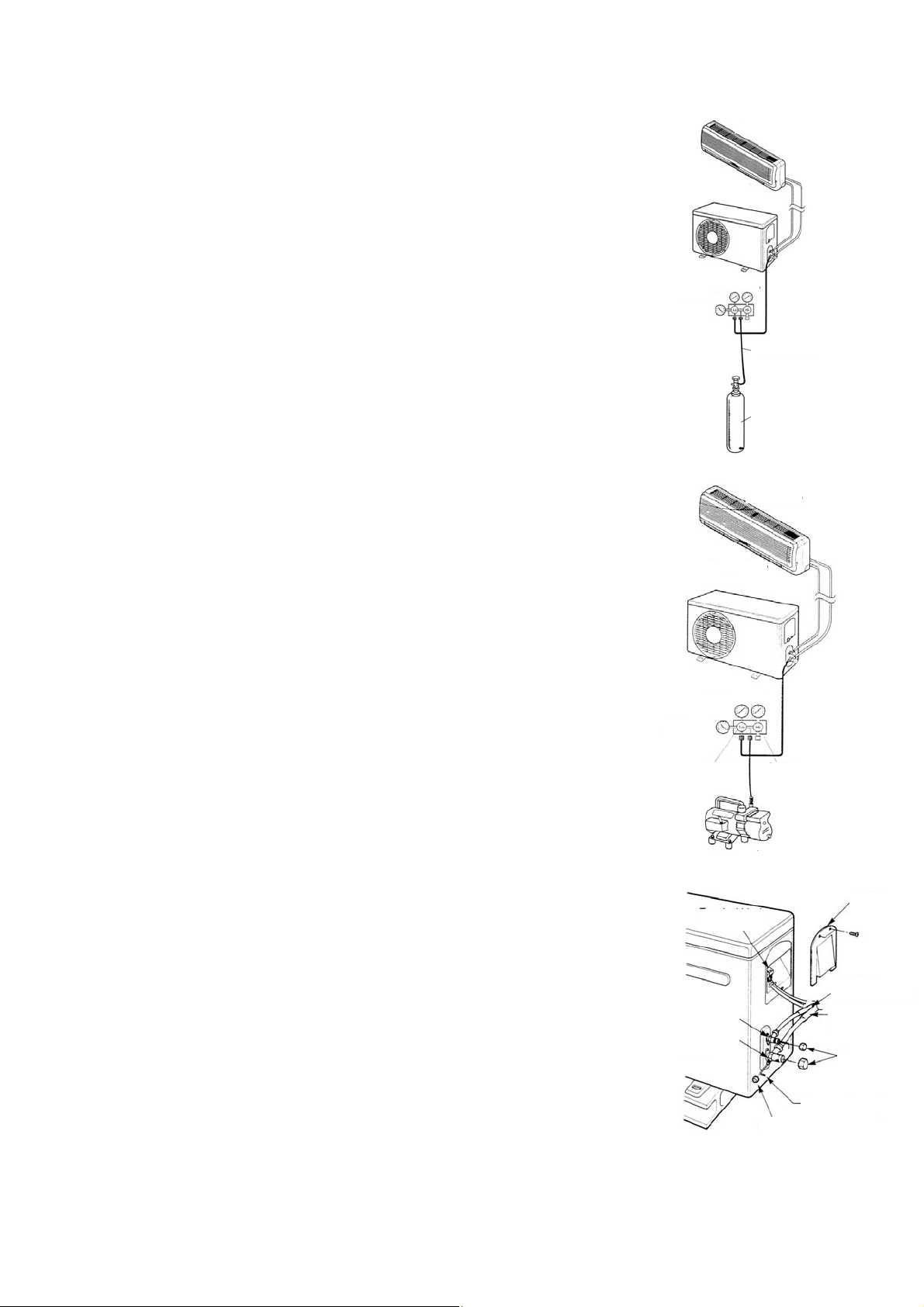
LUFTABLASSEN
Luft und Feuchtigkeit im Kühlsystem haben folgende unerwünschte Folgen:
Innengerät
● Druckanstieg im System
● Anstieg des Betriebsstroms
Außengerät
● Abfall der Kühl- bzw. Heizleistung
● Feuchtigkeit im Kühlkreislauf kann gefrieren und die feinen Rohre blockieren.
● Wasser kann Teile im Kühlsystem zum Rosten bringen.
Daher müssen das Innengerät und die Rohre zwischen Innen- und Außengerät auf
undichte Stellen überprüft und werden. Nicht kondensier bare Stoffe und Feuchtigkeit
Anzeigerdruck
Druck eicht
sind aus dem System zu entfernen.
Entlüftung mittels Vakuumpumpe
Gebührenschlauch
● Vorbereitung:
Überprüfen Sie, dass alle Rohre (an der Flüssigkeits- und an der Gas Seite)
zwischen dem Innen- und dem Außengerät richtig angeschlossen und alle Kabel für
Zylinder des Stick-
stoffgases (in ver-
tikaler Stellung)
den Probebetrieb fertig verlegt sind. Entfernen Sie die Deckel von den
Absperrventilen an der Gas und an der Flüssigkeitsseite des Außengerätes. Achten
Sie darauf, dass die Absperrventile an der Gas- und an der Flüssigkeitsseite des
Innengerät
Außengerätes geschlossen sind.
● Rohrlänge und Kühlmittelmenge, für eine einwandfreie Füllung den
Überheizungswert überprüfen. Die Werte der Tabelle sind weisend.
Außengerät
Siehe Röhrleitungstabelle:
● Wenn Sie das Gerät an einem anderen Ort aufstellen, entlüften Sie das Gerät mit
einer Vakuumpumpe.
● Achten Sie darauf, dass das nachgefüllte Kühlmittel stets flüssig ist.
Vorsicht mit dem verpackten Ventil
Druckmessventil
● Öffnen Sie den Ventilschaft so weit, bis er den Anschlag berührt. Versuchen Sie
nicht, ihn weiter zu öffnen.
● Ziehen Sie die Kappe des Ventilschafts mit einem Schrauben Schlüssel o.a. fest.
offen
geschlossen
● Drehmov ment Ventilschaftkappe (vgl. Drehmomenttabelle auf der vorhergehenden
Seite).
Einsatz der Vakuumpumpe
(Für den Einsatz des Blockventils s. die entsprechende Gebrauchsanweisung.)
Vakuum Pumpe
1. Ziehen Sie die Aufweitmuttern A, B, C, D ganz fest und schließen Sie den
Ladeschlauchdes Blockventils an einen Ladeanschluss des Niederdruckventils an der
Gasseite des Rohrs an.
Klemmleiste
2. Schließen Sie den Ladeschlauchanschluss an die Vakuumpumpe an.
3. Öffnen Sie den unteren Griff des Blockventils vollständig.
4. Betätigen Sie die Vakuumpumpe. Lösen Sie nach der Entleerung die Aufweis
tungs Mutter des Ventils unten an der Gasrohrseite und überprüfen Sie, dass Luft
eintritt. (Das Betriebsgeräusch der Vakuumpumpe ändert sich und der
2-Wege-Ventil (offen)
3-Wege-Ventil
(geschlossen)
Seite Flüssigkeit
Seite Gas
Kappe
Mischungsmesser zeigt 0 anstatt Minus an.)
5. Schließen Sie nach dem Entleeren den unteren Griff des Blockventils und stop pen
Sie die Vakuumpumpe. Entleeren Sie 15 Minuten oder länger und achten Sie darauf,
Sechskantschlüssel
Servicedeckel
dass der Mischungsmesser -76cmHg (-1 x10⁵Pa) anzeigt.
6. Drehen Sie den Schaft des verpackten B-Ventils 6-7 Sekunden nach dem Ausströ men des Gases etwa 45° entgegen
dem Uhrzeigersinn und ziehen Sie die Aufweist Mutter wieder fest. Achten Sie darauf, dass der angezeigte Druck etwas
Kontrolldeckel
16

höher ist als der Luftdruck.
7. Entfernen Sie den Ladeschlauch vom Niederdruckschlauch.
8. Öffnen Sie die verpackten Ventilschafte B und A.
9. Ziehen Sie die Kappe des verpackten Ventils gut fest.
9. BETRIEBSTEST
● Die Prüfung soll nur nach dem Ende der Installation durchgeführt werden.
● Prüfen Sie die folgenden Punkte vor der Prüfung über.
● Die Innen- und Außeneinheit sollen richtig installiert werden.
● Die Röhre und die Verkabelung sollen richtig verbunden werden.
● Führen Sie den Drucktest der Rohrleitungen durch.
● Das Drainagerohr soll richtig funktionieren.
● Die Wärmeisolierung soll richtig durchgeführt werden.
● Die Erdung soll richtig durchgeführt werden.
● Die Länge der Röhre und der Kältemittelfüllung sollen geprüft werden.
● Die Speisung soll der Speisung des Projekts entsprechen.
● Luftein- und Luftaustritten der Innen- und Außeneinheit sollen nicht blockiert sind.
● Die Gas -und Flüssigkeit Seite Ventile sollen geöffnet sind.
● Wärmen Sie die Klimaanlage durch die Spannung vor.
♦ PRÜFUNG
Stellen Sie durch die Fernbedienung (während der Kühlbetriebsart) das Klimagerät ein, und prüfen Sie die folgenden
Punkte über (wie in der Benutzung Sektion dieses Handbuches spezifiziert). Wenn gibt einige Fehler es, lösen Sie ihn durch
die Anweisungen der Störungen Sektion in diesem Handbuch.
1) Inneneinheit
a) Die Zündung und die Abschaltung durch die Fernbedienung sollen richtig angesetzt werden.
b) Die Tasten der Fernbedienung sollen wirkende sein.
c) Die Rippen oder Ableitbleche sollen regelmäßig funktionieren.
d) Die interne Temperatur soll richtig eingestellt werden.
e) Die Indikatoren auf dem Empfänger sollen richtig funktionieren.
f) Die manuelle Taste soll richtig funktionieren.
g) Der Kondensatabfluss soll regelmäßig funktionieren.
h) Prüfen Sie, ob seltsame Geräusche oder Vibrationen während des Betriebs gibt es.
j) Prüfen Sie, ob die Heizungsleistung ausreichende ist.
2) Außeneinheit
a) Prüfen Sie, ob das Vorhandensein von Lärm oder Vibrationen außerhalb der Norm ist.
b) Prüfen Sie eventuelle Verluste von Kältemittel Gas über.
VORSICHT!
17
Die Schutz-Funktion der Klimaanlage verhindert die direkte Zündung der Einheit nach der Abschaltung.
Nach der Eingriff des Schutzs, kann die Klimaanlage nach 3 Minuten wieder eingeschaltet werden.

FR
MANUEL D’UTILISATEUR
Climatiseur split
Winner Série
Modèle
Merci d’avoir choisi notre entreprise.
Pour un bon fonctionnement de l’appareil, veuillez lire et
conserver ce manuel soigneusement.
Conçu par Cooper & Hunter International Corporation , Oregon , États-Unis
www.cooperandhunter.com
:
CH-S09FTX5
CH-S12FTX5
CH-S18FTX5
CH-S24FTX5

INDICE
1. INFORMATIONS IMPORTANTES . . ................................................................................................................... 1
2. COMPOSANTES . ...............................................................................................................................................
3. AFFICHEUR . ......................................................................................................................................................
4. DESCRIPTION DE LA TELECOMMANDE . . ...................................................................................................... 3
4.1. Description des fonctions des touches de la télécommande . ..........................................................................
4.2. Description des indicateurs de l’afficheur de la télécommande . ......................................................................
4.3. Comment insérer / remplacer les piles . . ..........................................................................................................
4.4 Comment utiliser la télécommande pour faire fonctionner l’appareil . ...............................................................
4.5 Fonctionnement manuel . ..................................................................................................................................
5. ENTRETIEN . .......................................................................................................................................................
6. OPÉRATIONS ET PERFORMANCES . ..............................................................................................................
7. PROBLÈMES ET LEURS CAUSES . . ...............................................................................................................
8. INSTALLATION . ...............................................................................................................................................
9. ESSAI DE FONCTIONNEMENT . . ....................................................................................................................
2
2
3
3
4
4
7
8
9
11
12
18
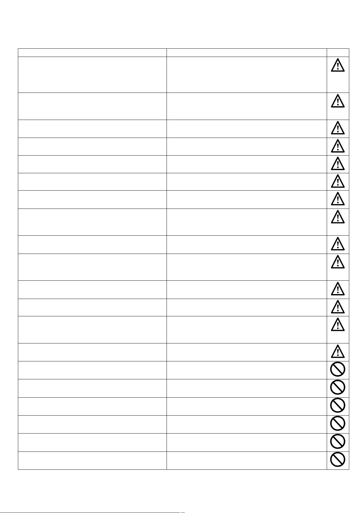
1. INFORMATIONS IMPORTANTES
REGLEMENTATION: RISQUE:
Electrocution par contact avec des composants sous tension.
N'effectuez aucune opération exigeant l'ouverture de
l'appareil
N'effectuez aucune opération exigeant la dépose de
l'appareil
N'utilisez pas la fiche du câble d'alimentation électrique pour
brancher ou arrêter l'appareil
N'abîmez pas le câble d'alimentation électrique Electrocution provoquée par des fils sous tension dénudés.
Ne posez jamais d'objets sur l'appareil Lésions provoquées par la chute de l'objet par suite de vibrations
Ne montez pas sur l'appareil Lésions provoquées par la chute de l'appareil.
Lésions sous forme de brûlures dues à la présence de
composants surchauffés ou de blessures provoquées par des
saillies et des bords tranchants.
Electrocution par contact avec des composants sous tension.
Lésions sous forme de brûlures dues au froid provoquées par le
gaz s'échappant des tuyaux débranchés.
Electrocution provoquée par le mauvais état du câble, de la fiche
ou de la prise.
Ne grimpez pas sur des chaises, des tabourets, des
échelles ou des supports instables pour nettoyer l'appareil.
N'effectuez aucune opération de nettoyage de l'appareil
sans avoir auparavant éteint l'appareil, débranché la fiche
ou désactivé l'interrupteur dédié.
Ne permettez pas à des enfants ou à des personnes
inexpérimentées d'utiliser l'appareil.
Ne dirigez pas le flux de l'air vers des plans décuisons ou
des poêles à gaz.
Ne glissez pas les doigts dans les bouches de sortie de l'air
et dans les grilles d'aspiration de l'air.
Ne buvez pas l'eau condensée. Lésions dues à intoxication.
Si vous sentez une odeur de brûlé ou si vous voyez de la
fumée s'échapper par l'appareil, coupez l'alimentation
électrique, ouvrez les fenêtres et appelez un technicien.
N'effectuez aucune opération exigeant la dépose de
l'appareil.
Ne posez jamais d'objets sur l'appareil.
N'utilisez pas d'insecticides, de solvants ou de produits de
nettoyage agressifs pour l'entretien de l'appareil.
N'utilisez pas l'appareil pour des usages autres qu'un usage
domestique habituel.
Ne permettez pas à des enfants ou à des personnes
inexpérimentées d'utiliser l'appareil.
Ne dirigez pas le flux de l'air vers des objets de valeur, des
plantes ou des animaux.
N'utilisez pas le climatiseur trop longtemps dans des
conditions d'humidité dépassant 80%.
Lésions provoquées par chute d'une hauteur élevée ou par
coupure (échelle pliante)
Electrocution par contact avec des composants sous tension.
Endommagement de l'appareil dû à un usage impropre.
Explosions, incendies ou intoxications à cause du gaz
s'échappant des injecteurs qui alimentent les flammes éteintes
par le flux d'air.
Electrocution par contact avec des composants sous tension.
Lésions provoquées par des coupures.
Lésions dues à des brûlures ou à inhalation de fumée.
Inondations dues à l'eau s'échappant des tuyaux débranchés.
Endommagement de l'appareil ou des objets placés en dessous
par la chute de l'appareil détaché de ses supports.
Endommagement des parties peintes ou en plastique.
Endommagement de l'appareil du fait d'une surcharge de
fonctionnement. Endommagement des objets indûment traités.
Endommagement de l'appareil dû à un usage impropre.
Endommagement ou dépérissement à cause de l'excès de
froid/chaleur, humidité, ventilation.
Endommagement d'objets par suintement excessif de l'appareil.
1

2. COMPOSANTES
Unité intérieure
(2)
(1)
(3)
(6)
(5)
(11)
(4)
(12 )
Unité extérieure
(10)
(7)
(8)
(9)
(1) Admission d’air
(2) Panneau frontal
(3) Commande manuelle
(4) Décharge d’air
(5) Déflecteur d’air vertical
(6) Filtre à air
(7) Admission d’air
(8) Tuyau de connexion
(9) Tuyau de vidange
(10) Décharge d’air
(11) Admission d’air
(12) Télécommande
3. AFFICHEUR
(5)
(3)
(4)
(2)
(6)
(1) LED récepteur de signal
(2) Indicateur opération
Cet indicateur clignote après la mise en marche de l’appareil et s’allume définitivement lors du fonctionnement.
(3) Indicateur de chauffage
Cet indicateur s’allume lors du fonctionnement du climatiseur en mode chauffage.
(4) Indicateur de refroidissement
Cet indicateur s’allume lors du fonctionnement de l’appareil en mode refroidissement.
(5) Indicateur température réglage
Indique les paramètres de température de lors du fonctionnement de l’appareil.
(6) Indicateur de déshumidification
Cet indicateur s’allume lors du fonctionnement de l’appareil. en mode de déshumidification.
(1)
2

4. DESCRIPTION DE LA TELECOMMANDE
4.1. Description des fonctions des touches de la télécommande
① La touche marche / arrêt permet de démarrer ou éteindre le climatiseur.
② La touche MODE permet de sélectionner le mode de fonctionnement: auto ( ),
refroidissement ( ), déshumidification ( ), ventilation ( ), chauffage ( ).
③ La touche FAN permet de sélectionner la vitesse de ventilation: Auto, Basse ( ),
Basse – Moyenne ( ), Moyenne ( ), Moyenne – Haute (
Auto
④ La touche TURBO active/désactive le mode de refroidissement et chauffage rapide.
⑤ Les touches de réglage ▲/▼ permettent d'ajuster la température ambiante et le
minuteur: les touches "▲" et "▲" servent pour augmenter et diminuer les valeurs des
paramètres température et temps.
⑥
La touche pour activer/désactiver le mouvement automatique des ailettes d’air vers
le haut et le bas.
⑦ La touche SLEEP, utilisée pour ajuster/annuler le mode SLEEP, indépendamment du
mode de fonctionnement actuel du climatiseur.
⑧
La touche IFEEL active/désactive la fonction IFEEL.
⑨ Les touches TIMER ON/TIMER OFF permettent d’ajuster l’heure de marche/arrêt
automatique.
⑩
La touche CLOCK permet d’ajuster l’heure actuelle.
⑪ La touche X-FAN permet de démarrer / arrêter le ventilateur interne, cette fonction
s’utilise pour sécher les composants du climatiseur.
⑫
La touche LIGHT pour illuminer ou éteindre l’afficheur du climatiseur.
⑬ La touche / permet d’ajuster la fonction de purification/circulation de l’air (la
fonction
⑭ La touche TEMP permet de visualiser sur l’afficheur du climatiseur la température du
point de consigne ou ambiante.
n’est pas disponible).
), Haute ( ).
2
13
14
10
4
1
5
3
6
8
7
9
11
12
4.2. Description des indicateurs de l’afficheur de la télécommande
: Indicateur mode AUTO.
: Indicateur mode REFROIDISSEMENT.
: Indicateur mode de DESHUMIDIFICATION.
: Indicateur mode de VENTILATION.
: Indicateur mode de CHAUFFAGE.
: Indicateur mode SLEEP.
: Indicateur HORLOGE.
H
U
R
O
N
O
O
-
F
F
: Indicateur TIMER ON-OFF.
: Indicateur TEMPERATURE.
: Indicateur FAN.
: Indicateur de PURIFICATION DE L’AIR.
: Indicateur mode QUIET (non disponible).
: Indicateur de la fonction de chauffage à 8°C.
: Indicateur de CIRCULATION DE L’AIR (non disponible).
: Indicateur mode LIGHT.
3
AFFICHEUR
A
U
O
T
F
A
N
A
U
TO
$
88
6
O
°
°
O
P
E
R
F
C
H
O
U
R
N
O
-
F
F
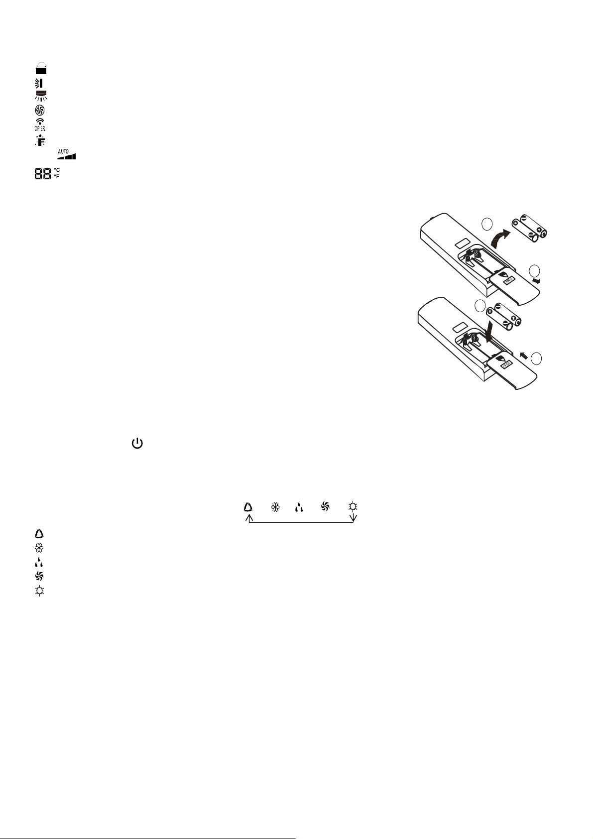
: Indicateur LOCK.
: Indicateur OSCILLATION AILETTES D’AIR verticales.
: Indicateur OSCILLATION AILETTES D’AIR vers la gauche (non disponible).
: Indicateur mode TURBO.
: LED de la confirmation de transmission de signal.
: Indicateur mode IFEEL.
FAN : Indicateur vitesse du ventilateur.
: Indicateur de la visualisation de température.
4.3. Comment insérer / remplacer les piles
Utiliser deux piles neuves alcalines 1,5 V de type AAA.
(1) Enlever le couvercle du siège des piles en le poussant vers le bas.
(2) et (3) Enlever les piles usées de la télécommande et insérer des nouvelles piles
alcalines AAA en respectant la polarité et fermer le couvercle du siège.
(4) Positionner le couvercle dans sa place en le poussant vers l’avant.
NOTES
♦ Ne jamais mettre ensemble des piles neuves et vieilles ou des piles de types
différentes. Ceci peut causer un mal fonctionnement de l’unité.
♦ Si la télécommande ne va pas utiliser pour longtemps, il faut enlever les piles pour
éviter des endommagements causés par d'éventuelles pertes.
♦ Les piles doivent être remplacées lorsque l’unité intérieure ne reçoit aucun signal
sonneur "bip" ou bien si l'indicateur de transmission sur la télécommande ne s'allume
pas.
♦ Placer la télécommande dans un endroit assurant la transmission correcte du signal.
4.4 Comment utiliser la télécommande pour faire fonctionner l’appareil
● MARCHE ARRÊT DE L’UNITÉ
Appuyer sur la touche pour démarrer ou arrêter l’unité.
2
1
3
4
● REGLAGE DU MODE DE FONCTIONNEMENT
En appuyant plusieurs fois sur la touche Mode pour changer le mode de fonctionnement de l'appareil. Sur l’afficheur se
visualise l’indicateur du mode de fonctionnement sélectionné comme suit:
→ → → →
: fonctionnement complètement automatique
: fonctionnement de refroidissement
: fonctionnement de déshumidification
: fonctionnement de seul ventilation
: fonctionnement de chauffage
Avec le choix du mode automatique AUTO, l’unité peut opérer en REFROIDISSEMENT ou en CHAUFFAGE en fonction de
la différence de température présente entre la température ambiante et la température du point de consigne sélectionnée à
l’aide de la télécommande.
Lorsqu’on sélectionne le mode de refroidissement, l’unité fonctionne avec une valeur libre de réglage de la température de
consigne, en baissant la température de l’air ambiant.
Lorsqu’on sélectionne le mode de déshumidification, l’unité fonctionne, avec une valeur de réglage libre de la température,
en baissant progressivement la température et l'humidité dans l'air ambiant. Avec le mode de déshumidification la touche
FAN n'est pas utilisable.
Lorsqu’on sélectionne le mode de chauffage, l’unité fonctionne avec une valeur de réglage de la température libre, en
augmentant la température dans l'air ambiant. Lorsqu’on sélectionne le mode de ventilation FAN, l’unité fonctionne sans
valeur de réglage pour la température de consigne, en ventilant seulement l'air ambiant.
4

IMPORTANT!
F
♦ Le ventilateur s'arrête une fois atteinte la valeur de température du point de consigne pour ensuite se
réactiver automatiquement à la vitesse minimale pour éviter le phénomène de stratification de l'air en proximité
de l'appareil.
♦ En sélectionnant le mode REFROIDISSEMENT, DESHUMIDIFICATION
, le ventilateur pourrait ne pas
démarrer tout de suite car est présente la fonction ANTI-CHAUFFAGE. En sélectionnant le mode
CHAUFFAGE, le ventilateur pourrait ne pas démarrer tout de suite car est présente la fonction
ANTIREFROIDISSEMENT.
● REGLAGE DES AILETTES
Pour obtenir une distribution optimale de l’air, ajuster la position des ailettes de l’air motorisées en faisant attention que le
flux d’air ne soit pas dirigé vers les personnes. Pour activer la fonction d’oscillation des ailettes, il faut:
1) Oscillation ailettes d’air verticales
Appuyer sur la touche pour sélectionner l’angle d’oscillation des ailettes, comme indiquée en bas:
OF
Note: Cette télécommande est universelle. Si la commande n'est pas reçue par l’appareil au moment de sa
transmission de la télécommande, le climatiseur déclenche l'oscillation des ailettes comme suit:
L’icône suivante indique que les ailettes oscillent comme suit:
2) Oscillation ailettes d’air horizontales (non disponible)
Appuyer sur la touche pour sélectionner l’angle d’oscillation des ailettes vers la gauche e la droite, comme indiquée en
bas:
OFF
● REGLAGE DE LA VENTILATION
Chaque fois où la touche "FAN" vient d’être appuyée, la vitesse de ventilation se change dans la séquence suivante:
Auto
Vitesse Auto, Vitesse Basse ( ), Vitesse Basse-Moyenne ( ), Vitesse Moyenne ( ), Vitesse Moyenne-Haute ( ),
Vitesse Haute (
).
● REGLAGE DE LA FONCTION IFEEL
Appuyez sur la touche IFEEL pour activer sa fonctionnalité. Dans ce cas, l'appareil ajuste automatiquement la température
ambiante en fonction de la température détectée par le capteur situé dans la télécommande.
Appuyez sur la même touche pour annuler cette fonction IFEEL.
● FONCTION DE PURIFICATION / CIRCULATION DE L’AIR (la fonction
n’est pas disponible)
Cette touche est utilisée pour activer /désactiver le mode de purification / circulation de l’air au moment d’opération du
climatiseur. En appuyant une seule fois la touche
l’indicateur “
”. En appuyant pour la deuxième fois la même touche, les fonctions de purification e de circulation de l’air
la fonction de circulation de l’air s’active et l’afficheur montre
s’activent au même temps et l’afficheur visualise les indicateurs “ ” et “ ”. En appuyant sur la même touche pour la
troisième fois, les fonctions précédentes vont se désactiver. En appuyant sur la même touche pour la quatrième fois, la
fonction de purification de l’air s’active et l’afficheur montre le symbole “ ”. Pour tourner au fonctionnement normal du
climatiseur, appuyer de nouveau sur la même touche.
● MODE SLEEP
Le mode "SLEEP" peut être ajusté durant le fonctionnement de chauffage ou de refroidissement.
Cette fonction est utile pour une ambiante plus confortable quand vous allez dormir.
En mode SLEEP:
- Le ventilateur s’ajuste automatiquement sur la basse vitesse.
- La température désirée augmente en mode de refroidissement ou diminue en mode chauffage avec 1°C à intervalles
prédéfinis. À partir de 2°C de variation, la machine maintient la température jusqu'à la huitième heure de fonctionnement en
mode "SLEEP" puis s'éteint automatiquement.
5
● FONCTION TEMP
La touche TEMP permet de visualiser sur l’afficheur de l’unité la température du point de consigne, ambiante intérieure et
ambiante extérieure.
Note: La température ambiante externe se visualise sur l’afficheur seulement pour quelques modèles.
● FONCTION QUIET (non disponible)
Pour activer le mode
pour le mode
de l’icône
: La fonction
Note
La vitesse du ventilateur ne peut être changée quand la fonction QUIET est active.
● REGLAGE
Appuyer sur la touche CLOCK pour ajuster l'horloge, utiliser les touches de réglage ''▲'' et ''▼'' pour ajuster l’heure
actuelle.
- En appuyant une seule fois sur la touche ''▲'' / ''▼'', l’heure augmente/diminue avec 1 minute.
- En appuyant sur la touche ''▲'' / ''▼'' pour presque 2 sec, l’heure augmente /diminue avec 10 minutes.
● REGLAGE DE LA MINUTERIE (
Utiliser les touches TIMER ON / TIMER OFF pour ajuster la programmation horaire et donc le démarrage et l’arrêt du
climatiseur.
- Comment ajuster la minuterie le TIMER ON
Appuyer sur la touche TIMER ON pour ajuster la programmation horaire de la mise en marche du climatiseur.
1) Appuyer la touche TIMER ON, l’indicateur disparaît de l’affichage et l’écriture "ON" clignotera sur l’afficheur, après,
utiliser les touches "▲" et "▼" pour ajuster l’heure désirée du démarrage programmé du climatiseur:
- Appuyer sur la touche "▲" ou "▼" une fois pour augmenter ou diminuer l’heure avec 1 minute.
- Appuyer sur la touche "▲" ou "▼" pour 2 secondes pour augmenter ou diminuer l’heure avec 10 minutes.
Note: Si vous n’ajustez pas l’heure entre 10 seconds après avoir appuyé sur la touche TIMER ON, la télécommande
quittera automatiquement le mode TIMER ON.
2) Quand l’heure désirée est visualisée sur l’afficheur LCD, appuyer sur la touche TIMER ON pour la confirmation. Un “son”
peut-être émis, l’écriture "ON" s’arrête de clignoter et l'indicateur TIMER sur l’unité interne s’illumine.
3) Après la visualisation du réglage TIMER, l'heure actuelle se visualisera sur l’afficheur de la télécommande.
- Comment annuler la minuterie (TIMER ON)
Appuyer de nouveau sur la touche TIMER ON, un "son" vient d’être émis et après l’indicateur disparu, et le mode TIMER
ON, s’annulera.
Note: La procédure est analogue pour ajuster le programme TIMER OFF, pour l’arrêt automatique du climatiseur à l’heure
programmée.
● MODE TURBO
- Le mode TURBO est utilisé pour démarrer ou arrêter le refroidissement et le chauffage rapide à vitesse maximale du
ventilateur.
- Dans le mode TURBO, il est possible d’ajuster la direction du flux d’air et la minuterie. Si vous désirer quitter le mode
TURBO, il suffit d’appuyer une touche quelconque entre: TURBO, MODE, FAN ou , l’afficheur retourne au mode original.
● FONCTION LIGHT
Lorsqu’on appuie sur la touche LIGHT, l’afficheur s’allume et l'indicateur vient d'être visualisé. En appuyant de nouveau
sur la même touche le précédent indicateur disparaît et l’afficheur s'éteint.
● FONCTION X-FAN
Si vous appuyez sur la touche
l’indicateur s’illumine dans l’écran et le ventilateur intérieur continue à fonctionner pour une durée de 10 minutes afin de
sécher les pièces à l’intérieure de l'unité, même si cette dernière est éteinte.
X-FAN OFF
durant le fonctionnement de l’unité en mode
QUIET
disparu. Au moment du démarrage du climatiseur, le réglage par défaut de l’usine est la fonction
DE L'HORLOGE
est la configuration par défaut au moment du démarrage de l'unité. La fonction
Auto QUIET
(l’afficheur visualise le symbole "
est désactivée durant le fonctionnement en mode de ventilation ou déshumidification.
QUIET
, il suffit d’appuyer sur la touche correspondante, (l’afficheur visualise le mot "
") au moment de la désactivation de la fonction
QUIET
TIMER)
X-FAN
durant le fonctionnement en mode de refroidissement ou de déshumidification,
n’est pas disponible
AUTO, VENTILATION
ou
CHAUFFAGE
X-FAN
.
Auto
, l’affichage
QUIET OFF
") et
.
6

● FONCTION
En appuyant simultanément sur les touches "▲" et "▼", la télécommande bloquera le dernier réglage de fonctionnement
programmé. Toutes les touches seront désactivées, comprenant aussi la touche . En appuyant de nouveau sur les
touches "▲" et "▼", les fonctions des touches seront activées.
● COMMUTATION ENTRE °C / °F
En appuyant simultanément la combinaison des touches "MODE" et "▼" quand le climatiseur est éteint, il sera possible de
choisir de visualiser la température en °C ou °F.
● FONCTION "ÉPARGNE ÉNERGITIQUE"
Appuyer simultanément la combinaison des deux touches "TEMP" et "CLOCK" durant le fonctionnement en mode de
refroidissement pour activer la fonction d’épargne d’énergie et l’afficheur de la télécommande montre l’écriture "SE". En
appuyant de nouveau la combinaison des deux touches pour annuler la dernière fonction.
● FONCTION DE CHAUFFAGE À 8°C
En appuyant simultanément la combinaison des deux touches "TEMP" ▲ "CLOCK" durant le fonctionnement de l’unité
chauffage, le mode de chauffage à 8°C (46°F) s’activera et l’afficheur de la télécommande visualise l’icône . Pour annuler
cette dernière fonction, il suffit d’appuyer de nouveau la combinaison des deux précédentes touches "TEMP" ▲ "CLOCK".
4.5. Fonctionnement manuel
Il est possible de faire fonctionner l’appareil manuellement de façon temporaire si vous ne trouvez pas la télécommande ou
si les piles sont expirées.
1. Ouvrez le panneau et soulevez-le jusqu'à un angle ou il fera click pour le fixer.
2. Si vous appuyez une fois sur la touche de commande manuelle, le mode de
fonctionnement forcé AUTO se met en marche.
3. Refermer fermement le panneau sur sa position d'origine.
Bouton contrôle
Manuel
ATTENTION:
● Si vous appuyez sur la touche de contrôle manuelle, la séquence de mise en marche est
la suivante: (CHAUFFAGE, REFROIDISSEMENT et VENTILATION) selon la température
ambiante.
● Appuyer sur le même bouton pour éteindre l'appareil.
7
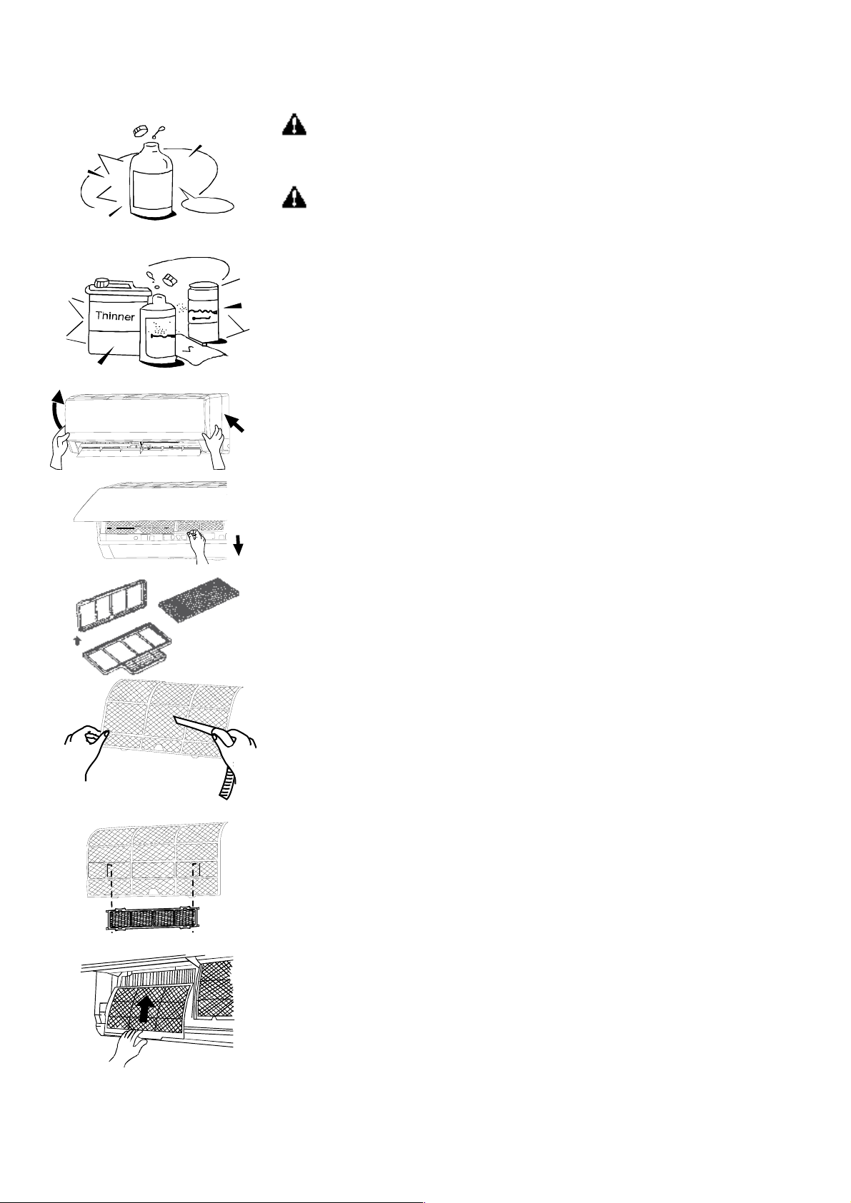
5. ENTRETIEN
Household
Drai n
Clea ner
No
ATTENTION
II est nécessaire d'éteindre le climatiseur et de le débrancher avant le nettoyage.
Nettoyage de l’unité intérieure et du télécommande.
PRÉCAUTIONS
● Utilisez un chiffon sec pour nettoyer l'unité intérieure et la télécommande.
● Un chiffon humidifié à l'eau froide peut éventuellement être utilisé pour nettoyer
l'extérieur de l'unité si elle est très sale.
● Le panneau frontal de l’unité intérieure peut être démonté et lavé à l’eau.
Essuyer-le ensuite avec chiffon sec.
● N'utilisez pas de chiffon traité chimiquement pour nettoyer l'unité.
● N'utilisez ni benzène, solvant, poudre à polir ou dissolvant similaire pour le nettoyage.
Cela pourrait craqueler ou déformer la surface en plastique.
Nettoyage du filtre à air
Un filtre à air bouché réduit l'efficacité de cette unité.
Veuillez nettoyer les filtres toutes les deux semaines.
1. Ouvrez le panneau de l'unité intérieure et soulevez-le jusqu'à un angle où il fera
click pour le fixer.
2. Agrippez le filtre par sa poignée et soulever-le légèrement pour le dégager de son
support, retirez-le ensuite.
3. Enlevez le FILTRE À AIR de l'unité intérieure.
● Nettoyez le filtre chaque deux semaines.
● Nettoyez le filtre à air avec un aspirateur ou avec de l'eau, puis laissez-le sécher
dans un endroit frais.
4. Retirez le filtre électrostatique de son support, tel qu'indiqué sur la figure de gauche
(n'est pas applicable aux unités sans filtre électrostatique).
Ne touchez pas le filtre électrostatique pendant 10 minutes après avoir ouvert la grille
d'admission, cela pourrait causer une décharge électrique.
● Nettoyez le filtre électrostatique avec un détergent neutre ou à l'eau et le laisser
sécher au soleil pendant deux heures.
● Avant de réinstaller le filtre électrostatique, vérifiez que sa couronne et son support
sont en bon état.
5. Posez le filtre rafraîchisseur à nouveau à sa place.
6. Insérez la partie supérieure du filtre à air dans l'unité en faisant attention à ce que
les arêtes gauches et droites soient correctement alignées, et positionnez le filtre.
Entretien
Si l'unité ne va pas être mise en marche pendant un certain temps, veuillez prendre
les précautions suivantes:
(1) Faire fonctionner le ventilateur pendant une demi-journée pour bien sécher
l'intérieure de l'unité.
(2) Éteignez le climatiseur et débranchez-le. Enlevez les piles de la télécommande.
(3) L'unité extérieure nécessite un entretien et un nettoyage régulier. N'essayez pas
de le faire vous- même. Contactez votre distributeur ou service d'entretien.
8

Vérifications avant la mise en marche.
● Vérifiez que le câblage n'est pas endommagé ou déconnecté.
● Vérifiez que le filtre à air est bien en place.
● Vérifiez si la décharge et l'admission d'air sont bloquées après une longue période d'inutilisation.
PRECAUTIONS
● Ne touchez pas les parties métalliques de l'appareil lors du retrait du filtre. La manipulation d'arêtes de métal agressives
peut causer des blessures.
● Ne laver pas l'intérieur du climatiseur avec l'eau. L'exposition à l'eau peut détruire les isolants et provoquer une décharge
électrique.
● Coupez l'alimentation électrique via le disjoncteur et le cordon d'alimentation lors du nettoyage de l'appareil.
6. OPÉRATIONS ET PERFORMANCES
Les circonstances suivantes peuvent se produire pendant le fonctionnement normal.
1. Protection du climatiseur
● Le compresseur met 3 minutes pour redémarrer après un arrêt.
Protection contre l'air froid (seulement sur les modèles réversibles)
● L'unité est conçue pour ne pas décharger d'air froid en mode chauffage quand l'échangeur de chaleur intérieur est dans
une des trois situations suivantes et que la température de thermostat n’a pas été atteinte:
A) Au tout début de la mise en marche.
B) Pendant le dégivrage
C) Si la température de chauffage est basse.
● Pendant le dégivrage, les ventilateurs intérieur et extérieur s'arrêtent (seulement sur les modèles réversibles). Dégivrage
(seulement sur les modèles réversibles)
● Du givre peut se former sur l'unité extérieure pendant le cycle de chauffe quand la température extérieure descend et que
l'humidité augmente, réduisant les performances de chauffage de l'appareil.
● Dans ces conditions de fonctionnement, le climatiseur arrêtera de chauffer et commencera un cycle automatique de
dégivrage.
● La durée de ce cycle varie entre 4 et 10 min, en fonction de la température extérieure et de la quantité de givre qui s'est
formé sur l'unité extérieure.
2. L'unité intérieure émet une buée blanche
● Une buée blanche peut se former à cause d'une grande différence de température entre l'air admis et l'air déchargé en
mode COOL (refroidissement) dans un environnement intérieur relativement humide.
● Une buée blanche due à l'humidité peut se produire après un cycle de dégivrage quand le climatiseur redémarre en mode
HEAT (chauffage).
3. Bruit faible du climatiseur
● Vous pouvez entendre un léger sifflement quand le compresseur est en marche ou vient de s'arrêter. Ce son est produit
par le flux ou l'arrêt de frigorigène.
● Vous pouvez également entendre un léger grincement quand le compresseur est en marche ou vient de s'arrêter. Ce
grincement est causé par la dilatation due à la chaleur et la contraction due au froid des pièces en plastique de l'unité quand
la température varie.
● Quand les déflecteurs se remettent à leur position initiale au moment de l'allumage, un léger bruit se produit.
4. L'unité intérieure émet de la poussière
Ceci est normal après une longue période d'inutilisation du climatiseur, ou après sa première mise en marche.
5. L'unité intérieure émet une odeur particulière
Cette odeur est due au passage d'odeurs de matériaux de construction, de mobilier ou de fumée au travers de l'unité
intérieure.
9

6. Le climatiseur se met en mode FAN ONLY (ventilation seule) depuis les modes COOL (refroidissement) ou HEAT
(chauffage) (seulement sur les modèles réversibles)
Quand la température intérieure atteint la température du thermostat, le compresseur s'arrête automatiquement, et le
climatiseur fonctionne en mode ventilation. Si la température intérieure augmente en mode froid, ou qu'elle descend en
mode chauffe, par rapport au thermostat, alors le compresseur se remet en marche (seulement sur les modèles
réversibles).
7. De l'eau peut apparaître sur la surface de l'unité intérieure en mode froid si l'humidité relative est importante
(supérieure à 80%).
Réglez le déflecteur horizontal au maximum de la décharge et sélectionnez HIGH pour la vitesse de ventilation.
8. Mode chauffage (seulement sur les modèles réversibles)
En mode chauffage, le climatiseur conduit de l'air chaud depuis l'unité extérieure et le libère vers l'unité intérieure. Quand la
température extérieure descend, la chaleur de l'air admis par le climatiseur descend également. En même temps, la charge
calorifique du climatiseur augmente à cause de la grande différence entre les températures extérieure et intérieure. Si vous
ne parvenez pas à atteindre une température confortable avec votre climatiseur, nous vous conseillons d'utiliser un
dispositif de chauffage supplémentaire.
9. Fonction de redémarrage automatique
Une coupure de courant pendant le fonctionnement éteindra le climatiseur.
Sur les modèles sans dispositif de redémarrage automatique, quand le courant est rétabli, l’indicateur de
FONCTIONNEMENT de l'unité intérieure commence à clignoter. Pour remettre l'appareil en marche, appuyez sur la touche
de la télécommande.
Sur les modèles munis d'un dispositif de redémarrage automatique, quand le courant est rétabli, l'appareil se remet en
marche automatiquement avec les paramètres de réglage établis auparavant.
10. Les éclairs ou l'utilisation d'un téléphone portable à proximité de l'appareil peut provoquer son
dysfonctionnement
Débranchez puis rebranchez alors l'appareil. Pour le remettre en marche, appuyez sur la touche
de la télécommande.
10

7. PROBLÈMES ET LEURS CAUSES
En cas de mal fonctionnement, mettez immédiatement l’appareil hors tension. Coupez l’alimentation électrique et contactez
le service clientèle le plus proche.
L’indicateur de fonctionnement, ou tout autre indicateur, se met à clignoter rapidement (5Hz) et
malgré le débranchement et la connexion de l’appareil, il continue à clignoter.
Problème
Symptôme Cause Qu’est-ce qu’il faut faire?
L’appareil ne démarre pas
Les fusibles ou le disjoncteur sautent souvent.
L’eau ou autre corps étrange pénètre dans le climatiseur.
La télécommande ne fonctionne pas ou son fonctionnement est anormal.
Autre situation anormale
Qu’est-ce qu’il faut faire? Attendre le rétablissement du courant
L’appareil est peut-être débranché Vérifier que la prise est correctement branchée
Le fusible peut-être sauté Remplacer le fusible
Les piles de la télécommande sont peut-être
expirées
Remplacer les piles
La programmation est incorrecte Attendre ou annuler la programmation
Température non appropriée du thermostat Régler correctement la température
Le filtre à air est bouché Nettoyer le filtre à air
Mauvaise performances
de refroidissement ou de
chauffage tandis que l’air
est déchargé
Des portes ou/et des fenêtres sont ouvertes Fermez les portes ou/et les fenêtres
Les orifices d’admission ou de décharge des
unités sont bloqués
Enlever ce qui obstrue les orifices avant de
redémarrer l’appareil
Les 3 minutes de protection du compresseur
sont activées.
Attendre
● Si les problèmes subsistent, veuillez contacter un distributeur local ou le service de réparation le plus proche.
● Assurez-vous d’en leur communiquer les indications précises concernant le type de panne et le modèle de l’appareil.
Remarque: N'essayez pas de réparer le climatiseur vous-même. Consultez toujours un service de réparation agréé.
11

8. INSTALLATION
Unité intérieure
● N'exposez pas l'unité intérieure á une source de chaleur ou de vapeur.
● Choisissez un emplacement libre d'obstacles devant et autour de l'unité.
● Assurez-vous que les condensais peuvent être facilement ou de vapeur.
● Choisissez un emplacement libre d'obstacles devant et autour de l'unité.
● Assurez-vous que les condensats peuvent être facilement évacues.
● N'installez pas cet appareil près d'une issue.
● Assurez-vous de laisser un espace de plus de 12 cm á gauche et á droite de l'appareil.
● Utilisez un détecteur de métaux pour localiser les montants de cloisons et ne pas abîmer les murs pour rien.
● Le tuyau doit mesurer au moins 3 mètres pour minimiser les vibrations et le bruit excessif.
● L'unité intérieure doit être installée sur le mur á une hauteur d'au moins 2,3 mètres du sol.
● L'unité intérieure doit être installée á au moins 15 cm du plafond.
60 cm
≤
m
≤ 15 cm
≤
m
c
5
1
m
c
5
1
≤
m
c
2
0
5
2
≤
≤
60 cm
0
≤ 50 c
0
2
m
c
5
1
≤
≤ 15 cm
● Toute modification de la longueur du tuyau devra faire l'objet d'un réglage de la charge frigorigène.
Unité extérieure
● Si vous décidez de poser une bâche sur l'unité extérieure pour la protéger des rayons solaires ou de la pluie, assurezvous que celle-ci ne restreint pas le rayonnement de chaleur du condensateur.
● Assurez-vous de laisser un espace de plus de 30cm á gauche et á l'arrière de l'unité. Un espace de plus de 200 cm doitêtre laissé devant l'unité, et de plus de 60 cm cote connexion (cote droit).
● Ne pas placer d'animaux ou de plantes dans le courant d'admission et de décharge d'air.
● Tenez compte du poids du climatiseur et choisissez un emplacement où le bruit et la vibration ne sont pas un problème.
● Choisissez un endroit ou le courant d'air chaud et le bruit du climatiseur ne dérangeront pas les voisins.
● Installez l'unité extérieure sur une base rigide afin d'éviter d'accroître le niveau de bruit et les vibrations.
● Déterminez une direction pour la décharge d'air où cette dernière ne sera pas bloquée.
● Dans le cas où le lieu d'installation serait exposé á des vents forts, tel que le bord de la mer, assurez-vous que le
ventilateur fonctionne correctement en plaçant la direction de la longueur de l'unité contre le mur ou en utilisant des volets
protecteurs.
● Notamment dans des zones exposées au vent, installez l'unité de façon à éviter l'admission de vent.
● Si l'appareil doit être suspendu, le support d'installation doit respecter les spécifications techniques du schéma
correspondant. Le mur où l'unité doit être installée doit être en brique pleine, en béton ou densité similaire. Si cela n'est pas
le cas, il faut renforcer et amortir les supports. Les connexions entre le support et le mur et le support et le climatiseur
doivent être fermes, stables et fiables.
Assurez-vous qu'il n'y a pas d'obstacle á l'émission d'air.
12

Installation en toiture:
● Si vous posez l'unité extérieure sur une toiture, veillez á niveler l'appareil. Assurez-vous que la structure du toit et que le
mode d'ancrage sont appropriés pour la pose de l'appareil.
● Consultez la réglementation locale concernant les installations en toiture.
● Si l'unité extérieure est installée sur une toiture ou mur extérieur, les bruits et vibrations pourraient être excessifs, et
l'installation pourrait être également déclarée inutilisable.
1. Pose de la plaque de montage
1. Posez la plaque de montage horizontalement sur un des éléments structures du mur et de façon á laisser un espace
autours.
2. Si le mur est en briques, et béton ou similaire, percer 5 trous de 5 mm de diamètre dans le mur. Introduire les chevilles
de montage correspondant aux vis appropriées.
3. Fixer la plaque de montage sur le mur avec 5 vis de type ST4.2X25TA.
Mod. 2600 W, 3500 W
Mur
Distanzce
du mur
supérieur
Gauche
(Trou tuyauteriepostérieure)
Signe au milieu
Distanzce
du mur
supérieur
Droite
Mur
Indicateur de niveau
(Trou tuyauteriepostérieure)
Mur Mur
Distanzce
du mur
supérieur
Gauche
Signe au milieu
Mod. 5300 W
(Trou tuyauteriepostérieure)(Trou tuyauteriepostérieure)
Indicateur de niveau
Distanzce
du mur
supérieur
Droite
Mod. 7000 W
Mur Mur
Distanzce
du mur
supérieur
Signe au milieu
Gauche
(Trou tuyauteriepostérieure)
Indicateur de niveau
Distanzce
du mur
supérieur
Droite
(Trou tuyauteriepostérieure)
2. Perçage d'un trou dans le mur
1. Déterminer la position des trous en fonction du diagramme détaillé á la figure en haut . Percer un (1) trou (diamètre
indiqué dans plaque de montage) en haut légèrement incliné vers l'extérieur.
2. Utilisez toujours une traversée de mur pour percer une grille de métal, une plaque de métal ou similaire.
3. Installation du tuyau de raccordement et du drainage
1. Posez le tuyau d'évacuation en l'inclinant vers le bas. N'installez pas le tuyau d'évacuation tel qu'indiqué ci-dessous.
2. Quand vous connectez le prolongement du tuyau d'évacuation, isoler les connexions de prolongement avec un manchon
protecteur, ne pas laisser le tuyau avoir du mou.
Tuyau de raccordement
1. Pour faire sortir la tuyauterie vers la gauche ou vers la droite, enlever la plaque de fermeture du panneau latéral.
● Expliquez au client que les plaques de fermeture doivent être conservées car elles peuvent être utiles lors d'un
déplacement du climatiseur á un autre endroit.
2. Pour installer la tuyauterie vers l'arrière aussi bien pour la gauche que pour la droite, suivez les explications. Coudez le
tuyau de raccordement qui doit être posé au plus á 43mm de haut du mur.
3. Fixez l'extrémité du tuyau de raccordement. (Cf. Serrage des connexions au chapitre RACCORDEMENT DE LA
TUYAUTERIE DE FRIGORIGÉNE).
13

4. Installation unité intérieure
,35/Φ9,
,35/Φ9,
,35/
,35/
1. Faites passer le tuyau par le trou percé dans le mur.
2. Posez la griffe d'accrochage supérieure située á l'arrière de. L'unité intérieure sur le crochet supérieur de la plaque de
montage, puis bougez l'unité d'un cote et de l'autre pour vérifier qu'elle est bien accrochée.
3. Le raccordement peut être effectué en soulevant l'unité intérieure du mur á l'aide d'un matériau de rembourrage. Enlevezle quand vous aurez terminé le raccordement.
4. Poussez la partie inférieure de l'unité intérieure vers le mur. Remuez alors l'unité intérieure de chaque côte et de haut en
bas pour vérifier qu'elle est correctement accrochée.
Tuyauterie et recouvrement
Rassemblez la tuyauterie, les câbles de connexion et le tuyau d'évacuation dans un faisceau maintenu fermement avec une
bande adhésive, tel qu'indiqué dans la figure en bas.
● L’eau du condensat de l'unité intérieure est recueilli dans un bac à condensats et évacuée hors de la pièce.
IMPORTANT
● Raccordez l'unité intérieure en premier, puis l'unité extérieure.
● Ne laissez pas sortir directement les tuyaux de derrière l'unité intérieure.
● Veillez á ce que le tuyau d'évacuation soit bien tendu.
● Isolez la tuyauterie auxiliaire de la chaleur.
● Assurez-vous que le tuyau d'évacuation est situé en bas du faisceau. Si
vous le posez sur le dessus, vous risquez de faire déborder les
Unité
intérieure
u
a
y
u
T
c
e
v
a
Cinta aislante
Cables de
connexion
z
t
a
n
g
me
e
l
o
s
i
ya
liq
u
u
u
T
a
m
e
le
o
ve
is
c
Tuyau de vidange
condensais dans l'unité.
● Ne croisez ni ne tordez jamais le cordon électrique avec un autre câble.
● Posez le tuyau d'évacuation incliné vers le bas afin que les condensais soient évacues sans obstacles.
● Les câbles d'alimentation ne doivent entrer en contact avec les tuyauteries.
Modèles (W)
1 x 1 DC INV.
2600 W
3500 W
5300 W
7000 W
Longueur max. sans réfrigérant
supplémentaires (m)
5 15 10 20 Φ6
5 20 10 20 Φ6
5 25 10 20 Φ6
5 25 10 50 Φ6
Longueur max. tuyau
de connexion (m)
Dénivelé (m)
Quantités supplémentaires
Frigorigène (g/m)
Φliquide/Φgaz
52
52
Φ12,7
Φ16
id
t
n
14

Câblage électrique
N
N
Câblage de l'unité intérieure
1. Le câble de connexion intérieur/extérieur doit être de type H07RN-F.
2. Soulevez le panneau de l'unité intérieure, enlever la vis et retirer le couvercle de la
boite de câblage électrique.
3. Connectez les câbles aux bornes d'après leurs marques.
4. Recouvrez les câbles non connectés avec du chatterton, pour qu'ils n'entrent pas en
contact avec les composants électriques.
Câblage de l'unité extérieure
1. Retirez le couvercle du boîtier électrique de l'unité extérieure.
2. Connectez les câbles aux bornes identifiées par leur numérotation respectives sur les
borniers des unités intérieure et extérieure.
3. Afin d'éviter l’entrée d'eau, formez une boucle ascendante avec le câble de
connexion, tel qu'indiqué sur le schéma de d'installation des unités intérieure et
extérieure.
4. Isolez les câbles non utilisés (conducteurs) avec du ruban PVC afin qu'ils n'entrent
pas en contact avec un composant électrique ou une partie métallique.
Caractéristiques technique des câblages
Modèles (W)
1 x 1 DC INV.
Câble de connexion de
l'alimentation électrique
Section Section
2600 W, 3500 W 3 x 1.5 mm² 4 x 0,75 mm²
5300 W, 7000 W 3 x 1.5 mm² 4 x 0,75 mm²
Câble de connexion entre unités
intérieure-extérieure
à l'unité extérieure
à l'unité extérieure
Panneau frontal Bornier
Unité intérieure
Couvercle pour bornier
Unité extérieure
Alimentation
électrique
Calibre disjoncteur
du circuit (A)
20 A (240V)
25 A (240V)
Les schémas de connexion
1 x 1 DC INVERTER (Mod. 2600 W, 3500 W) 1 x 1 DC INVERTER (Mod. 5300 W, 7000 W)
BARRETTE DE CONNEXION
UNITÉ EXTÉRIEURE
BU
BK
BN
ALIMENTATION ÉLECTRIQUE
L
BARRETTE DE CONNEXION
UNITÉ INTÉRIEURE
BU
BK
BN
BARRETTE DE CONNEXION
UNITÉ EXTÉRIEURE
BU
BK
BN
ALIMENTATION ÉLECTRIQUE
L
BARRETTE DE CONNEXION
UNITÉ INTÉRIEURE
BU
BK
BN
15

RACCORDMENT DE LA TUYAUTERIE DE FRIGORIGENE
1. Travaux d'évasement
La cause principale de fuite de frigorigène réside dans des travaux d'évasement défectueux
Veuillez suivre la procédure suivante lors des travaux d'évasement:
A: Découpe des tuyaux et du câble
1. Utilisez le kit d'accessoires de tuyauterie ou les tuyaux achetés sur place.
2. Mesurez la distance entre l'unité intérieure et l'unité extérieure.
3. Coupez les tuyaux un peu plus longs que la distance mesurée.
4. Coupez le câble 1,5 m plus long que la longueur du tuyau.
B: Ébarbement
1. Éliminez complètement les ébarbures de la section de coupe des tuyaux/tubes.
2. Dirigez l'extrémité du tuyau/tube en cuivre vers le bas lors de l'élimination des
ébarbures, afin qu'elles ne tombent pas dans le tuyau.
C: Pose des écrous
Enlever les écrous de raccords évasés qui sont livrés avec les unités intérieure et extérieure, les insérer sur le tube/tuyau
complètement ébarbé (il n'est pas possible de les poser après l'évasement).
D: Travaux d'évasement
Maintenir le tuyau fermement dans une filière en fonction du tableau en bas.
Diam. ext. (mm)
Φ 6,35 1,3
Φ 9,52
Φ12,7
Φ 16
Serrage du raccordement
● Alignez les centres des tuyaux
● Vissez suffisamment l'écrou faire á la main, puis procédez au serrage á l'aide d'une clé
plate et d'une clé dynamométrique tel qu'indiqué
IMPORTANT
● Un couple de serrage excessif peut casser les écrous selon les conditions d'installation.
A(mm)
Max. Min.
0,7
1,6
1,8
2
1
1
1
D iam . Ext. (mm ) C ouplede torsion (N.m )
Φ 6,35
Φ 9,52
Φ 12,7
Φ 16
15 ~ 20
31 ~ 35
50 ~ 55
60 ~ 65
Tuyau
16
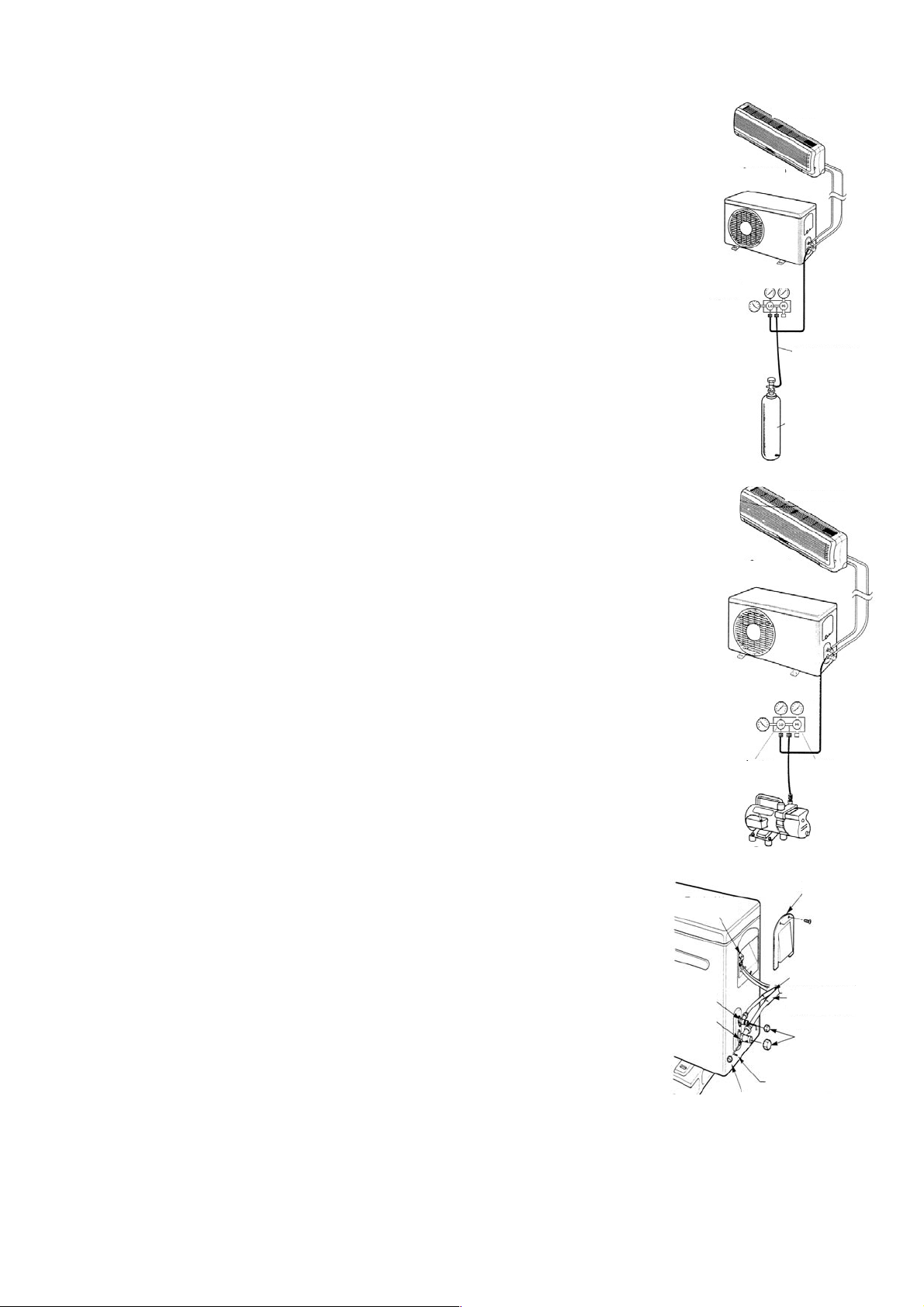
PURGE D'AIR
Unité intérieure
L'air et l'humidité dans le système de réfrigération peuvent avoir les effets indésirables
suivants:
● Augmentation de la pression dans le système.
Unité extérieure
● Augmentation de la tension de fonctionnement.
● Baisse d'efficacité de refroidissement ou de chauffage.
● L'humidité contenue dans le circuit de réfrigération peut congeler et bloquer les tubes
capillaires.
● L'eau peut conduire à la corrosion de certaines pièces du système de réfrigération. Par
conséquent, il faut tester le système pour vérifier qu'il n'y a pas de fuites au niveau de
Indicateur de
Manomètres
pressione
l'unité intérieure et des tuyaux de raccordement à l'unité extérieure, et évacuer et éliminer
toute humidité et substance non condensable du système.
Tuyau de charge
Purge d'air avec pompe à vide
● Préparation: Vérifiez que chaque tuyau (aussi bien de fluide que de gaz) est bien
connecté entre les unités intérieure et extérieure et que le câblage de marche d'essai est
Bouteille de gaz
d'azote (en position
verticale)
terminé. Enlever les capuchons des vannes de service côté gaz et fluide de l'unité
extérieure. Observez qu'à ce stade, les vannes de service de gaz et de fluide sont encore
fermées.
Unité intérieure
● Longueur de tuyau et quantité de frigorigène, pour un correcte rechargement, vérifiez la
valeur de sur-chauffage.
● Si vous déplacez l'unité, purgez avec une pompe à vide.
● Assurez-vous que le frigorigène ajouté dans le climatiseur est toujours sous forme
Unité extérieure
liquide.
Précautions lors de la manipulation de la vanne de service
● Ouvrez l'aiguille de la vanne jusqu'à ce qu'elle touche le stoppeur. N'essayez pas de
l'ouvrir plus.
● Serrez fermement le capuchon de protection avec une clé plate ou similaire.
● Le couple de serrage du capuchon est indiqué sur le tableau des couples de serrage de
Indicateur de
pressione
Manomètres
la page précédente.
Utilisation de la pompe à air
Ouvert
Fermé
(pour savoir comment utiliser une vanne manifold, consultez son manuel de
fonctionnement)
1) Serrez à fond les écrous de raccords évasés A, B, C, D, connecter le tuyau de charge
du manifold à l'orifice de charge de la vanne basse pression côté conduite de gaz.
2) Connectez le raccord du tuyau de charge à la pompe à vide.
3) Ouvrez à fond la manette Lo du manifold.
Bloc de borne
Pompe à vide
Couverture
4) Mettez la pompe à vide en marche pour évacuer l'air. Après le début de
l'opération, desserrez légèrement l'écrou de raccord évasé de la vanne Lo
côté conduite de gaz et vérifiez que l'air entre. (Le bruit de fonctionnement de
la pompe à vide change et le vacuomètre doit indiquer 0 au lieu de moins).
5) Une fois que le vide est fait, fermer à fond la manette Lo du manifold et
éteindre la pompe à vide. Faites le vide pendant 15 minutes ou plus et
Vanne à 3 voies
Vanne à 2 voies
(Ouverte)
Côté liquide
Côté gaz
Bouchon
vérifiez que le vacuomètre indique -76cmHg (-1x10⁵Pa).
6) Tournez la tige de la vanne de service B 45° vers la droite pendant 6 ou 7
secondes après la sortie de gaz, et serrez à nouveau l'écrou de raccord
Clef hexagonale
Bouchon de service
évasé. Assurez-vous que la pression indiquée par le manomètre est légèrement supérieure à la pression atmosphérique
7) Enlevez le tuyau de charge de l'orifice basse pression.
8) Ouvrir complètement les tiges des vannes de service B et A.
9) Refermer à fond le capuchon de la vanne de service.
17

9. ESSAI DE FONCTIONNEMENT
● Le test doit être effectué uniquement après avoir terminé l'installation.
● Vérifiez les points suivants avant d'exécuter le test.
● Les unités interne et externe doivent être installées correctement.
● Les tuyaux et les câbles électriques doivent être connectés correctement.
● Test de pression de la tuyauterie effectué.
● Le drainage fonctionne correctement.
● L'isolation thermique a été réalisée correctement.
● La mise à terre a été réalisée correctement.
● La longueur des tubes et la charge de réfrigérant ont été vérifiées.
● La tension d'alimentation correspond à la tension du projet pour l'unité.
● Les entrées et les sorties d'air des unités internes et externes ne sont pas obstruées.
● Les vannes du côté gaz et du côté liquide sont ouvertes.
● Le climatiseur a été préchauffé en lui donnant tension.
♦ Test de fonctionnement
■ Réglez par la télécommande le climatiseur en mode refroidissement, et vérifiez les points suivants comme indiqué dans la
partie de l‘usager dans ce manuel. S’il y a des dysfonctionnements, cherchez-les à l’aide des instructions de la section
«DYSFONCTIONNEMENTS» de ce manuel.
1) Unité interne
a) Vérifiez si le démarrage et l’arrêt par la télécommande se font correctement.
b) Vérifiez si les touches de la télécommande fonctionnent correctement.
c) Vérifiez si les ailettes oscillent régulièrement.
d) Vérifiez si la température interne est correctement ajustée.
e) Vérifiez si les indicateurs sur le récepteur fonctionnent.
f) Vérifiez si la touche manuelle fonctionne correctement.
g) Vérifiez si le vidange se fait de façon régulière.
h) Vérifiez s'il y a des bruits inhabituels ou des vibrations lors du fonctionnement.
j) Vérifiez si le chauffage est suffisant.
2) Unité externe
a) Vérifiez la présence des bruits ou vibrations en dehors de la norme.
b) Vérifiez s'il y a des fuites de gaz réfrigérant.
ATTENTION
La fonction de protection du climatiseur empêche le démarrage immédiat après son arrêt. Après l’intervention de
la protection, on peut redémarrer de nouveau l’appareil après environ 3 minutes de son arrêt.
18
IT
MANUALE DEL PROPRIETARIO
Condizionatori d’aria Split
Winner Serie
MODELLO
Grazie per aver scelto il nostro prodotto.
Per assicurare il funzionamento corretto, leggere attentamente e
conservare il presente manuale.
Progettato da Cooper & Hunter International Corporation , Oregon , Stati
Uniti d’America
www.cooperandhunter.com
:
CH-S09FTX5
CH-S12FTX5
CH-S18FTX5
CH-S24FTX5

INDICE
1. INFORMAZIONI IMPORTANTI . ......................................................................................................................... 1
2. COMPONENTI . . .................................................................................................................................................
3. DISPLAY . . .......................................................................................................................................................... 2
4. DESCRIZIONE TELECOMANDO . ..................................................................................................................... 3
4.1. Descrizione funzioni tasti del telecomando . . ...................................................................................................
4.2. Descrizione indicatori del display .. ..................................................................................................................
4.3. Come inserire/sostituire le batterie . .................................................................................................................
4.4. Come utilizzare il telecomando per far funzionare l’unità . . .............................................................................
4.5. Funzionamento manuale . ................................................................................................................................
5. MANUTENZIONE . ..............................................................................................................................................
6. OPERAZIONI E PRESTAZIONI . ........................................................................................................................
7. MALFUNZIONAMENTI ......................................................................................................................................
8. INSTALLAZIONE ...............................................................................................................................................
9. PROVA DI FUNZIONAMENTO . .......................................................................................................................
2
3
3
4
4
7
8
9
10
11
18

1. INFORMAZIONI IMPORTANTI
NORMA: RISCHIO:
Folgorazione per presenza di componenti sotto tensione.
Non effettuare operazioni che implichino l’apertura
dell’apparecchio.
Non effettuare operazioni che implichino la rimozione
dell’apparecchio dalla sua installazione.
Non avviare o spegnere l’apparecchio inserendo o
staccando la spina del cavo di alimentazione elettrica.
Non danneggiare il cavo di alimentazione elettrica. Folgorazione per presenza di fili scoperti sotto tensione.
Lesioni personali per ustioni per presenza di componenti
surriscaldati o per ferite per presenza di bordi e
protuberanze taglienti.
Folgorazione per presenza di componenti sotto tensione.
Lesioni personali per ustioni da raffreddamento per
fuoriuscita di gas dalle tubazioni scollegate.
Folgorazione per danneggiamento del cavo, o della spina, o
della presa.
Non lasciare oggetti sull’apparecchio.
Lesioni personali per la caduta dell’oggetto a seguito di
vibrazioni.
Non salire sull’apparecchio. Lesioni personali per la caduta dall’apparecchio.
Non salire su sedie, sgabelli, scale o supporti instabili
per effettuare la pulizia dell’apparecchio.
Lesioni personali per la caduta dall’alto o per cesoia mento
(scale doppie).
Non effettuare operazioni di pulizia dell’apparecchio
senza aver prima spento l’apparecchio, staccato la
Folgorazione per presenza di componenti sotto tensione.
spina o disinserito l’interruttore dedicato.
Non fare utilizzare l’apparecchio da bambini o
persone inesperte.
Non dirigere il flusso dell’aria verso piani di cottura o
stufe a gas.
Non inserire le dita nelle bocchette di uscita aria e
nelle griglie di aspirazione aria.
Danneggiamento dell’apparecchio per uso improprio.
Esplosioni, incendi o intossicazioni per il flusso gas dagli
ugelli di alimentazione fiamme spente dal flusso d’aria.
Folgorazione per presenza di componenti sotto tensione.
Lesioni personali per tagli.
Non bere l’acqua di condensa. Lesioni personali per intossicazione.
Nel caso si avverta odore di bruciato o si veda del
fumo fuoriuscire dall’apparecchio, togliere
l’alimentazione elettrica, aprire le finestre ed avvisare
Lesioni personali per ustioni o inalazioni fumi.
il tecnico.
Non effettuare operazioni che implichino la rimozione
dell’apparecchio dalla sua installazione.
Allagamenti per perdita acqua dalle tubazioni scollegate.
Danneggiamento dell’apparecchio o degli oggetti sottostanti
Non lasciare oggetti sull’apparecchio.
per la caduta dell’apparecchio a seguito del distacco dal
fissaggio.
Non utilizzare insetticidi, solventi o detersivi aggressivi
per la pulizia dell’apparecchio.
Non utilizzare l’apparecchio per scopi diversi da
quello di un normale uso domestico.
Non fare utilizzare l’apparecchio da bambini o
persone inesperte.
Non dirigere il flusso dell’aria verso oggetti di valore,
piante o animali.
Non usare il condizionatore per molto tempo in
condizioni di umidità superiore all’80%.
Danneggiamento delle parti in materiale plastico o verniciate.
Danneggiamento dell’apparecchio per sovraccarico di
funzionamento.
Danneggiamento degli oggetti indebitamente trattati.
Danneggiamento dell’apparecchio per uso improprio.
Danneggiamento o deperimento per eccessivo freddo/
caldo, umidità, ventilazione.
Danneggiamento oggetti per gocciolamento eccessiva
condensa dall’apparecchio.
1

2. COMPONENTI
(6)
(2)
UNITA’ INTERNA
(5)
(11)
(4)
(12 )
(1)
(7)
(3)
(8)
(1) Ingresso aria
(2) Griglia frontale
(3) Pannello di controllo
(4) Uscita aria
(5) Alette flusso aria
(6) Filtri aria
(7) Ingresso aria
(8) Tubazioni connessione
(9) Scarico condensa
(10) Uscita aria
(11) Ingresso aria
(12) Telecomando
(9)
(10)
UNITA’ ESTERNA
3. DISPLAY
(5)
(3)
(4)
(2)
(6)
(1) LED ricevitore segnale
(2) Indicatore operation
Questo indicatore si illumina durante l’accensione del condizionatore.
(3) Indicatore di riscaldamento
Questo indicatore si accende durante l’operazione del condizionatore in modalità di riscaldamento.
(4) Indicatore di raffreddamento
Questo si illumina durante l’operazione del condizionatore in modalità di raffreddamento.
(5) Indicatore temperatura impostata
Questo indicatore visualizza la temperatura impostata durante il funzionamento del condizionatore.
(6) Indicatore di deumidificazione
Questo indicatore si illumina durante l’operazione del condizionatore in modalità di deumidificazione.
(1)
2
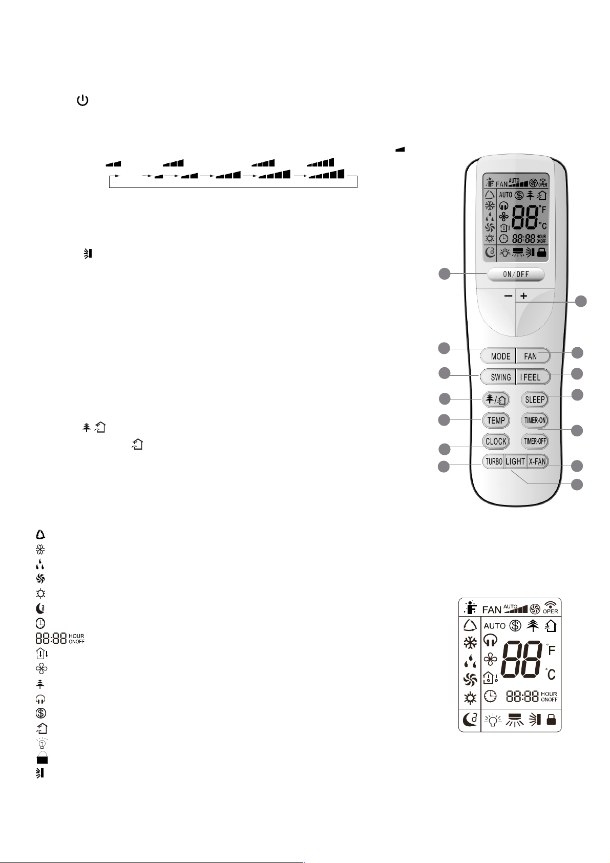
4. DESCRIZIONE TELECOMANDO
4.1. Descrizione funzioni tasti del telecomando
① Tasto , consente di spegnere e accendere il condizionatore.
② Tasto MODE permette di selezionare la modalità di funzionamento: AUTO - COOL-
DRY - FAN - HEAT.
③ Tasto FAN permette di selezionare la velocità della ventilazione: Auto, Bassa ( ),
Bassa - Media ( ), Media ( ), Media - Alta (
Auto
④ Tasto TURBO attiva/disattiva la modalità di raffreddamento e riscaldamento rapido.
⑤
Tasti di regolazione consentono di regolare la temperatura ambiente interna e il timer:
“
▲” ne imposta l’aumento, “▼” ne imposta la diminuzione.
⑥
Il tasto per attivare o disattivare il movimento automatico del deflettore d’aria verso
su e giù.
⑦ Il tasto SLEEP è usato per impostare/cancellare la modalità SLEEP,
indipendentemente dal modo in cui sta operando il condizionatore.
⑧ Tasto I FEEL attiva/disattiva la funzione I FEEL.
), Alta ( ).
⑨ Tasto TIMER ON/TIMER OFF consentono di impostare l’orario di accensione /
spegnimento in automatico.
⑩
Tasto CLOCK consente di impostare l’orario corrente.
⑪ Il tasto X-FAN consente di avviare / arrestare il ventilatore interno, questa funzione si
utilizza per asciugare i componenti dell’unità interna.
⑫ Il tasto LIGHT è utilizzato per accendere o spegnere il display dell’unità.
⑬
Il tasto / permette di impostare la funzione di purificazione/rinnovo dell’aria (la
funzione rinnovo aria non è disponibile).
⑭
Il tasto TEMP permette di visualizzare sul display dell’unità la temperatura impostata o
quella ambiente.
2
13
14
10
4
TELECOMANDO
1
5
3
6
8
7
9
11
12
4.2. Descrizione indicatori del display
: Indicatore modalità AUTO.
: Indicatore modalità di RAFFREDDAMENTO.
: Indicatore modalità di DEUMIDIFICAZIONE.
: Indicatore modalità di VENTILAZIONE.
: Indicatore modalità di RISCALDAMENTO.
: Indicatore modalità SLEEP.
: Indicatore OROLOGIO.
: Indicatore TIMER ON-OFF.
: Indicatore TEMPERATURA.
: Indicatore FAN.
: Indicatore DEPURATORE ARIA.
: Indicatore modalità QUIET.
: Indicatore funzione riscaldamento in 8°C.
: Indicatore modalità RINNOVO ARIA (non è disponibile).
: Indicatore modalità LIGHT.
: Indicatore LOCK.
: Indicatore oscillazione deflettore verticale.
3
DISPLAY

: Icona oscillazione deflettore sinistra & destra (non è disponibile).
: Indicatore modalità TURBO.
: LED conferma trasmissione segnale.
: Indicatore modalità I FEEL.
FAN : Indicatore velocità ventilatore.
: Indicatore visualizzazione temperatura.
4.3. Come inserire/sostituire le batterie
Usare due batterie alcaline 1,5 V tipo AAA.
① Rimuovere il coperchio delle batterie facendolo scivolare nella direzione della
freccia.
② e ③ Rimuovere le batterie vecchie e inserire le nuove facendo attenzione ad
2
allineare correttamente le polarità (+) e (-).
④ Chiudere il coperchio delle batterie facendolo scivolare nella sua posizione.
Note:
- Non mettere insieme batterie nuove con vecchie o batterie di tipo differente. Ciò
può essere causa di malfunzionamento.
- Se non si usa il telecomando per un lungo periodo, le batterie devono essere tolte
per evitare danni causati da eventuali perdite.
- Le batterie vanno sostituite quando non si riceve alcun "bip" dall’unità interna o se
l’indicatore di trasmissione sul telecomando non si accende.
- Posizionare il telecomando nell’apposito supporto fissato a muro (per assicurare la
trasmissione corretta del segnale).
3
1
4
4.4. Come utilizzare il telecomando per far funzionare l’unità
● ACCENSIONE SPEGNIMENTO DELL’UNITÀ
Premere il tasto per accendere o spegnere l’unità.
● IMPOSTAZIONE DELLA MODALITÀ DI FUNZIONAMENTO
Premendo più volte il tasto Mode è possibile cambiare la modalità di funzionamento dell’unità. Sul display compare
l’indicazione della modalità di funzionamento selezionato:
→ → → →
: funzionamento completamente automatico
: funzione raffreddamento
: funzione deumidificazione
: funzionamento solo ventilazione
: funzione riscaldamento
Con la scelta della modalità AUTO, l’unità può operare in RAFFREDDAMENTO od in RISCALDAMENTO in base alla
differenza di temperatura esistente tra la temperatura ambiente e la temperatura selezionata sul telecomando.
Quando viene scelta la modalità di raffreddamento, l’unità funziona con set di temperatura libero, abbassando la
temperatura in ambiente.
Quando viene scelto la modalità di deumidificazione, l’unità funziona, con set di temperatura libero, abbassando così
progressivamente la temperatura e l’umidità in ambiente. Nella modalità di deumidificazione il tasto FAN non è utilizzabile.
Quando viene scelto il programma di riscaldamento, l’unità funziona, con set di temperatura libero, alzando la temperatura
in ambiente. Quando viene scelta la modalità di ventilazione FAN, l’unità funziona senza set di temperatura, ventilando l’aria
dell’ambiente.
4

IMPORTANTE!
F
♦ Il ventilatore dell’unità si ferma al raggiungimento del valore di temperatura impostato per poi riattivarsi
automaticamente alla velocità minima per evitare fenomeni di stratificazione dell’aria in prossimità
dell’apparecchio.
♦ Selezionando la funzione RAFFREDDAMENTO, DEUMIDIFICAZIONE, il ventilatore potrebbe non avviarsi
subito perché presente la funzione ANTI-RISCALDAMENTO. Selezionando la funzione riscaldamento, il
ventilatore potrebbe non avviarsi subito perché presente la funzione ANTI-RAFFREDDAMENTO.
● IMPOSTAZIONE OSCILLAZIONE DEL DEFLETTORE
Per ottenere una distribuzione ottimale dell’aria, regolare la posizione del deflettore motorizzato avendo cura che il flusso
d’aria non investa direttamente le persone. Per il deflettore motorizzato agire nella modalità seguente:
1) Oscillazione deflettore su e giù
Premendo il tasto è possibile selezionare l’angolo di oscillazione come indicato sotto:
OF
Note: Questo telecomando è universale. Se il comando (SWING su e giù) non viene inviato all’unità, essa attiva
l’oscillazione del deflettore come .
indica che il deflettore oscilla come:
2) Impostazione oscillazione destra e sinistra (non è disponibile)
Premere il tasto per attivare o disattivare la funzione oscillazione sinistra & destra.
OFF
● IMPOSTAZIONE DEL VENTILATORE
Premendo più volte il tasto FAN è possibile impostare la velocità del ventilatore tra le tre disponibili, oppure attivare la
funzione AUTO. Sul display compare la modalità di funzionamento:
Auto
Velocità Auto, Velocità Bassa ( ), Velocità Bassa-Media ( ), Velocità Media ( ), Velocità Media-Alta ( ), Velocità
Alta (
).
● IMPOSTAZIONE DELLA FUNZIONE IFEEL
Premere il tasto IFEEL per attivare la funzione. In questo caso l'unità regola automaticamente la temperatura ambiente in
base alla temperatura rilevata dal sensore di temperatura posizionato nel telecomando.
Premere nuovamente questo tasto per annullare la funzione IFEEL.
●
Questo tasto
FUNZIONE DEPURAZIONE / CIRCOLAZIONE (RINNOVO) ARIA (la funzione non è disponibile)
è usato per attivare/disattivare la modalità di depurazione / circolazione dell’aria quando il condizionatore
è in funzione.
Premendo una volta il tasto
la funzione di circolazione dell’aria si attiva ed il display visualizza l’indicatore " ".
Premendo per una seconda volta lo stesso tasto, le funzioni di depurazione e circolazione dell’aria si attivano
contemporaneamente ed il display visualizza gli indicatori "
" e " ". Premendo sullo stesso tasto per la terza volta, le
funzioni precedenti vengono disattivate. Premendo sullo stesso tasto per la quarta volta, la funzione di depurazione dell’aria
si attiva ed il display visualizza l’icona "
". Per tornare al normale funzionamento del condizionatore, premere nuovamente
sullo stesso tasto.
● MODALITÀ SLEEP
La modalità "SLEEP" può essere impostata nel funzionamento di riscaldamento o di raffreddamento.
Questa funzione è utile per un ambiente più confortevole quando si va a dormire.
Nella modalità SLEEP:
- La velocità del ventilatore viene impostata sulla bassa.
- La temperatura impostata aumenta (diminuisce) di 1°C se il condizionatore funziona in modalità di raffreddamento
(riscaldamento). Quando la temperatura impostata varia con 2°C la macchina mantiene la temperatura fino all’ottava ora di
funzionamento in modalità “SLEEP”, per poi spegnersi automaticamente.
5

● FUNZIONE TEMP
Tasto TEMP permette di visualizzare sul display dell’unità la temperatura impostata, ambiente interna e ambiente esterna.
Note: La temperatura ambiente esterna viene visualizzata sul display solamente per alcuni modelli.
● FUNZIONE QUIET (non è disponibile)
Per attivare la modalità Auto
scritta "
l’indicazione
predefinita di fabbrica.
: La funzione
Nota
La velocità del ventilatore non può essere cambiata quando la funzione QUIET è attiva.
●
IMPOSTAZIONE DELL'OR’LOGIO
Premere il tasto CLOCK per regolare l'orologio, utilizzare i tasti di regolazione ''▲'' e ''▼''’ ’’reimpostare l'ora attuale.
- Una singola pressione del tasto ''▲''/''▼'', incrementa/decrementa l'orario di 1 minuto.
- Una pressione del tasto ''▲'' /''▼'' per circa 2 secondi, incrementa/decrementa l'orario di 10 minuti.
●
IMPOSTAZIONE DEL TIMER
Utilizzare i tasti TIMER ON / TIMER OFF per impostare la programmazione oraria e quindi l’accensione e lo spegnimento
del condizionatore.
- Come impostare TIMER ON
Premere il tasto TIMER ON per impostare la programmazione oraria dell’accensione del condizionatore.
1) Premere il tasto TIMER ON, l’indicatore
che usare i tasti ''▲'' e ''▼'' per impostare l’ora desiderata per l’accensione programmata del condizionatore:
- Premere il tasto ''▲'' o ''▼'' ’una volta per aumentare o diminuire l’orario di 1 minuto.
Nota: Se non regolate l'orario entro 10 secondi dopo aver premuto il tasto TIMER ON, il telecomando abbandonerà
automaticamente la modalità TIMER ON.
2) Per confermare l'orario desiderato, premere il tasto TIMER ON. Un “suono” può essere sentito, e la scritta “ON” smette di
lampeggiare.
3) Il display del telecomando visualizza l'orario attuale subito dopo l'impostazione del TIMER ON.
- Come cancellare TIMER ON
Premere di nuovo il tasto TIMER ON, "un suono" può essere sentito dopodiché l'indicatore sparisce, e la modalità TIMER
ON verrà cancellata.
Nota: È analogo per impostare la modalità TIMER OFF per spegnere automaticamente il condizionatore all'or’ impostata.
● MoDALITÀ TURBO
- La modalità TURBO è usata per avviare o arrestare il raffreddamento e il riscaldamento rapido a massima velocità di
impostazione.
- In questa modalità TURBO, si possono regolare la direzione del flusso d'aria e il timer. Se si desidera uscire dalla modalità
TURBO, è sufficiente premere un tasto qualsiasi tra: TURBO, MODE, FAN o , il display ritorna alla modalità originale.
● FUNZIONE LIGHT
Premere il tasto
spegnerlo dopodiché l’indicazione scompare dal display.
● FUNZIONE X-FAN
Se il tasto
visualizzata l'indicatore ed il ventilatore interno continua a girare per altri 10 minuti per asciugare l’interno dell’unità,
anche se essa è stata spenta.
Al momento dell’accensione dell’unità, la funzione X-FAN OFF è l’impostazione predefinita di fabbrica. X-FAN è disattiva nel
funzionamento in modalità AUTO, VENTILAZIONE o RISCALDAMENTO
") e per la modalità
Auto
scompare dal display. Al momento dell’accensione dell’unità, la funzione
è disabilitata durante il funzionamento in modalità di ventilazione o deumidificazione.
QUIET
- Premere il tasto ''▲'' o ''▼'' per una durata di 2 secondi per aumentare o diminuire l’orario di 10 minuti.
per accendere la luce del display e si mostra l’indicatore LIGHT . Premere nuovamente per
LIGHT
X-FAN
viene premuto durante il funzionamento di RAFFREDDAMENTO o DEUMIDIFICAZIONE, il display
, è sufficiente premere il corrispondente tasto a questa funzione, (il display visualizza la
QUIET
QUIET
(il display visualizza il simbolo "
scompare dal display mentre la scritta "ON“ comincia a lampeggiare, dopo di
" se viene disattivata la modalità
QUIET OFF
è l’impostazione
QUIET
,
6

● LOCK FUNCTION
o
Premendo contemporaneamente i tasti "▲" e "▼" il telecomando bloccherà l’ultima operazione impostata.
Tutti i tasti di comando vengono disattivati, incluso il tasto di accensione / spegnimento . Premendo nuovamente i due tasti
"▲" e "▼" si riattiveranno le funzioni dei tasti.
● FUNZIONE °C / °F
Premendo contemporaneamente i due tasti "MOME" e "▼" a unità spenta, si potrà scegliere se visualizzare la temperatura
in °C o °F.
● FUNZIONE "RISPARMIO ENERGIA"
Premere contemporaneamente i due tasti "TEMP" e "CLOCK" nel funzionamento in raffreddamento per attivare la funzione
di risparmio energetico ed il display del telecomando mostra la scritta "SE". Premere nuovamente la combinazione di due
tasti per annullare l’ultima funzione.
● FUNZIONE DI RISCALDAMENTO A 8°C
Premendo contemporaneamente i due tasti "TEMP" e "CLOCK" durante il funzionamento di riscaldamento, la modalità di
riscaldamento a 8°C (46°F) viene attivata ed il display del telecomando visualizza il simbolo . Per annullare l’ultima
funzione; è sufficiente premere nuovamente la combinazione di tasti "TEMP" e "CLOCK".
4.5. Funzionamento manuale
È possibile far funzionare l'apparecchio manualmente in modo temporaneo se non trovate il telecomando o se le batterie
sono morte.
1. Aprire il pannello e sollevarlo fino ad un angolo o farà click per fissarlo.
2. Premendo per una volta sul tasto di comando manuale, la modalità di funzionamento
forzato AUTO si mette in marcia.
3. Richiudere fermamente il pannello sulla sua posizione d'origine.
Tasto controll
manuale
Attenzione
● Premendo il tasto di comando manuale, La modalità di funzionamento viene selezionata
in base alla temperatura interna: RAFREDDAMENTO/RISCALDAMENTO/VENTILAZIONE.
● Premendo lo stesso tasto per spegnere l'apparecchio.
7

5. MANUTENZIONE
Household
Drai n
Clea ner
No
Attenzione
Quando si pulisce l'unità, assicurarsi che la spina di alimentazione elettrica e il circuito
siano spenti.
Pulizia dell’unità interna e del telecomando
Avvertenze
● Usare un panno asciutto per strofinare l'unità interna e il telecomando.
● Un panno inumidito con acqua fredda può essere usato per pulire l'unità esterna se
è veramente sporca.
● Il pannello frontale dell’unità interna può essere rimosso e pulito
con acqua. Asciugarlo quindi con un panno asciutto.
● Non utilizzare panni trattati chimicamente per pulire l’unità.
● Non usare benzina, solventi, detergenti in polvere o solventi simili per la pulizia.
Questi possono causare la rottura o la deformazione della superficie plastica.
Pulizia del filtro
L’intasamento del filtro dell’aria diminuisce il rendimento dell’unità. Pulire il filtro ogni
due settimane.
1) Sollevare il pannello dell’unità interna fino al punto in cui si blocca con un clic.
2) Afferrare la maniglia del filtro dell’aria e sollevare leggermente per sganciare il
filtro dal supporto filtro, quindi tirare verso il basso.
3) Estrarre il filtro dell’aria dall’unità.
- Pulire il filtro dell’aria ogni due settimane.
- Pulire il filtro dell’aria con un aspirapolvere o dell’acqua, e poi asciugarlo in un luogo
fresco e asciutto.
4) Rimuovere il filtro depuratore d’aria dal suo supporto (ove presente.)
Non toccare Il filtro elettrostatico al plasma nei primi 10 minuti dopo l'apertura della
griglia per non correre il rischio di una scarica elettrica.
● Pulire il filtro al Plasma con acqua, e se necessario, con un detergente delicato e
quindi esporlo per l'asciugatura al sole per almeno 2 ore.
5) Posizionare il filtro dell’aria come richiesto
6) Mettere la parte superiore del filtro dell’aria nel condizionatore e assicurarsi che i
margini sinistro e destro siano correttamente allineati, quindi inserire il filtro nella sua
posizione.
Manutenzione
Se pensate di non usare l'unità per un lungo periodo:
1) Accendete la ventola per almeno mezza giornata per asciugare l'interno dell'unità;
2) Fermare il condizionatore e staccare la corrente; rimuovere le batterie dal
telecomando.
3) L'unità esterna richiede manutenzione e pulizia periodica. Non operare
personalmente, contattare il servizio tecnico.
8

Verifiche prima del funzionamento.
● Verificare che l'impianto elettrico non sia mal funzionante o disconnesso.
● Verificare che il filtro dell'aria sia installato.
● Verificare che la presa e lo scarico dell'aria non siano bloccati dopo che il condizionatore è rimasto inutilizzato per lungo
tempo.
ATTENZIONE
● Non toccare le parti metalliche dell'unità quando si rimuove il filtro poiché ci si potrebbe ferire.
● Non usare acqua per pulire il condizionatore all'interno, potrebbe distruggere l'isolamento e causare un corto circuito.
● Quando si pulisce l’unità, assicurarsi che la spina e il circuito siano spenti.
6. OPERAZIONI E PRESTAZIONI
I seguenti eventi possono avvenire durante il funzionamento normale.
1. Protezione del condizionatore
Protezione del compressore
- Il compressore impiegherà 3 minuti per partire dopo l'arresto.
Anti-aria Fredda
- L'unità è studiata per non emettere aria fredda in modalità di riscaldamento, quando lo scambiatore di calore dell'unità
interna è in una delle seguenti situazioni e la temperatura impostata non è stata raggiunta.
A) Quando è appena cominciato il riscaldamento.
B) Sbrinamento.
C) Bassa temperatura di riscaldamento.
Se l'unità esterna è coperta di brina, l'operazione di sbrinamento si attiverà automaticamente (per circa 4-10 minuti) per
mantenere gli effetti del riscaldamento.
- I ventilatori di entrambe le unità interna e esterna, si fermeranno durante l'operazione di sbrinamento.
- Durante l'operazione di sbrinamento, la condensa viene convogliata sul piatto del fondo dell'unità esterna.
2. Fumo generato dall'unità interna
- Può fuoriuscire del fumo dall'unità interna a causa della grande differenza di temperatura tra ingresso ed uscita dell'aria, in
modalità raffreddamento, e l'alta umidità presente nell'ambiente da rinfrescare.
- Può generarsi fumo grazie all'umidità generata dal processo di sbrinamento quando il climatizzatore viene riavviato in
modalità riscaldamento.
3. Piccoli rumori del climatizzatore
Si può udire un rumore tipo "ss" causato dal flusso di refrigerante.
Si può udire un rumore tipo "zz" causato dalla dilatazione della plastica causata dalla variazione di temperatura.
All'accensione si recepisce un rumore dovuto all'apertura delle alette.
4. Della polvere fuoriesce dall'unità interna
Ciò è normale quando il climatizzatore non è stato usato per un lungo periodo o durante il primo uso dell'unità.
5. Un particolare odore fuoriesce dall'unità interna.
Ciò è causato dall'unità interna che emette degli odori pervasi da materiale di costruzione, da mobilia, o da fumo.
6. Il climatizzatore cambia in modalità VENTILAZIONE dalla modalità di riscaldamento o raffreddamento (per i
modelli di raffreddamento e di riscaldamento soltanto)
Quando la temperatura interna raggiunge la temperatura d'impostazione, il compressore si arresterà automaticamente e
l'unità partirà modalità di ventilazione. Il compressore si riavvierà nuovamente quando la temperatura dell'interna aumenta
9

in modalità di raffreddamento o raggiunge la temperatura impostata in modalità di riscaldamento (per i modelli di
raffreddamento e di riscaldamento soltanto).
7. Dell'acqua può apparire sulla superficie dell'unità interna in modalità di raffreddamento se l'umidità relativa è alta
(superiore all'80’)
Regolare il deflettore orizzontale al massimo dello scarico d'aria e scegliere la velocità alta di ventilazione.
8. In modalità di riscaldamento, il climatizzatore confluisce l'aria calda dall'unità esterna all'unità interna
Quando la temperatura esterna diminuisce, il calore dell'aria ammessa dal climatizzatore diminuisce. Allo stesso tempo, il
carico calorifico del climatizzatore aumenta a causa della grande differenza tra le temperature esterna ed interna.
9. Funzione d'avviamento automatico
Un'interruzione di corrente durante il funzionamento spegnerà il climatizzatore.
Sui modelli senza dispositivo AUTORESTART, quando la corrente è ristabilita, l'indicatore di FUNZIONAMENTO dell'unità
interna inizia a lampeggiare. Per riavviare l'apparecchio, premere sul tasto
del telecomando. Sui modelli muniti di
AUTORESTART, quando la corrente è ristabilita, l'apparecchio si riavvia automaticamente con i parametri di funzionamento
precedentemente impostati.
10. I lampi o l'utilizzo di un telefono portatile vicino all'apparecchio possono causare malfunzionamenti
Staccare poi ricollegare l'apparecchio. Per riavviarlo, premere il tasto del telecomando.
7. MALFUNZIONAMENTI
In caso di malfunzionamento, togliere l’alimentazione all'apparecchio e contattare il servizio assistenza più vicino.
L'indicatore di funzionamento, o qualsiasi altro indicatore, si mette a lampeggiare rapidamente
(5Hz) e nonostante la sconnessione e la riconnessione dell'apparecchio, continua a lampeggiare.
MALFUNZIONAMENTI
Errore Causa Soluzione
L’unità non parte
Fusibile o circuito dell’interruttore intervengono frequentemente.
L'acqua o altro corpo sconosciuto è penetrato nel climatizzatore.
Il telecomando non funziona o il suo funzionamento non è normale.
Altre condizioni inconsuete.
Interruzione corrente. Attendere il ripristino della corrente.
L'apparecchio è staccato. Verificare se la presa è correttamente collegata.
Il fusibile è saltato. Sostituire il fusibile.
Le batterie del telecomando sono scariche. Sostituire le batterie.
La programmazione è sbagliata. Attendere o annullare la programmazione.
Temperatura impostata non adeguata. Regolare correttamente la temperatura.
Il filtro d’aria è otturato. Pulire il filtro d’aria.
L’unità non climatizza
correttamente l’ambiente.
Porte o finestre sono aperte. Chiudere le porte o le finestre.
Sono bloccati l’ingresso o l’uscita dell’aria.
I 3 minuti di protezione del compressore
sono attivati.
Eliminare ciò che blocca il flusso dell’aria prima di
riavviare l'apparecchio.
Attendere
Nel caso di presenza dei problemi, si prega di contattare il fornitore locale o il servizio d’assistenza più vicino.
Assicurarsi di dare le indicazioni precise che riguardino il tipo di guasto ed il modello dell'apparecchio.
Nota: Non cercare a riparare il climatizzatore da soli. Contattare sempre un centro d’assistenza autorizzato.
10
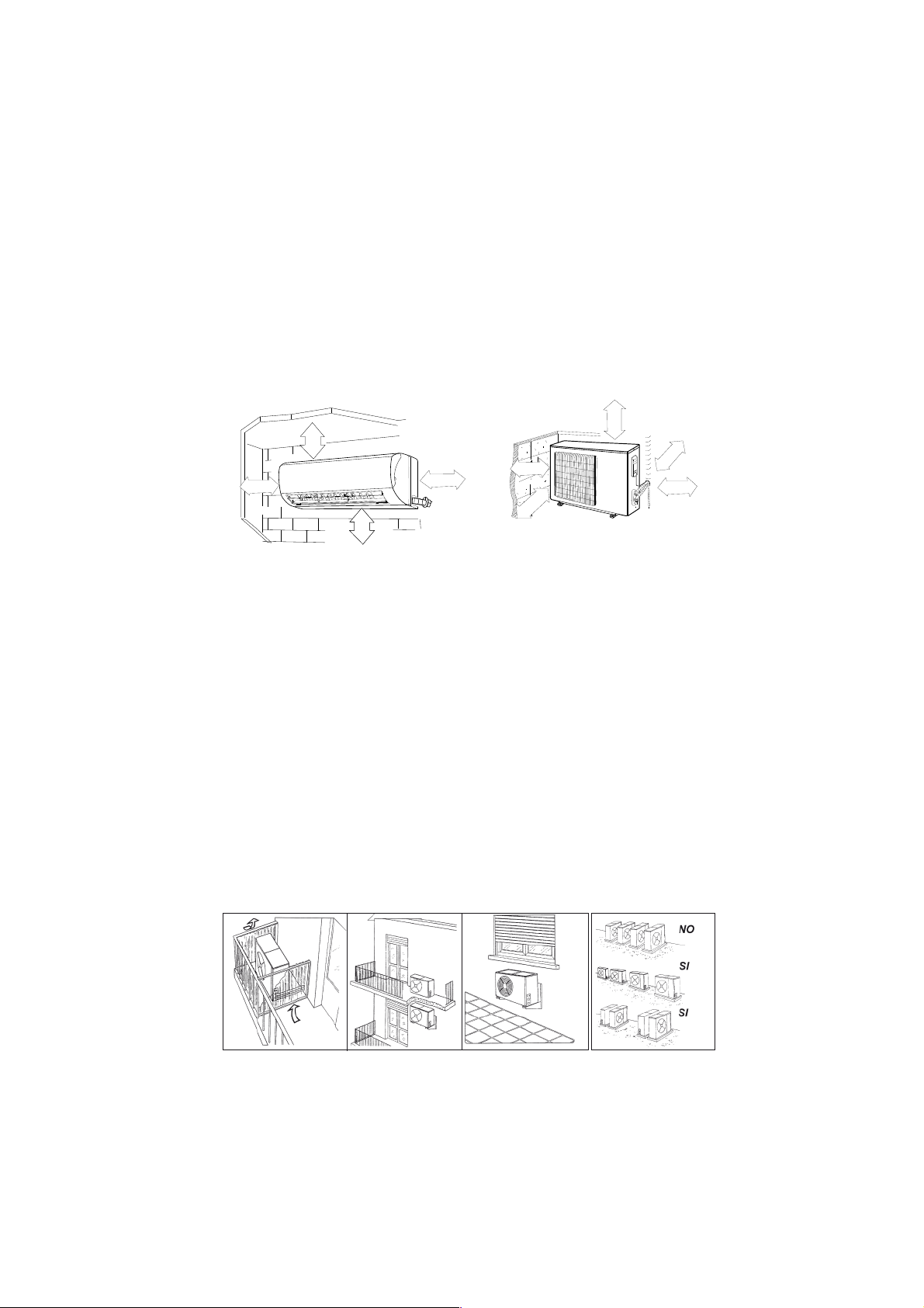
8. INSTALLAZIONE
Unità interna
● Non esporre l'unità interna a calore o a vapore.
● Installare rispettando le distanze indicate, nella parte anteriore e intorno all'unità.
● Assicurarsi che lo scarico condensa funzioni.
● Non installare vicino ad una porta.
● Accertarsi che lo spazio sul lato destro e sinistro dell'unità sia maggiore di 12 cm.
● Prima di eseguire i fori accertarsi di controllare il passaggio di linee elettriche o tubazioni nella parete.
● Il tubo del refrigerante che collega le due unità non deve essere inferiore ai tre metri, onde evitare vibrazioni e rumore
eccessivo.
● L'unità interna dovrebbe essere installata sulla parete ad un'altezza di 2-3 m dal pavimento.
● L'unità interna dovrebbe essere installata ad una distanza minima di 15 cm dal soffitto.
● Se si prolunga il tubo che collega le due unità bisogna sempre aggiungere la quantità di refrigerante
60 cm
≤
≤ 15 cm
m
c
5
1
m
c
5
1
≤
m
c
2
50
2
≤
≤
≤
60 cm
5
0
≤
0
2
m
c
0
cm
5
1
≤
≤ 15 cm
Unità esterna
corrispondente.
● Quando l’unità lavora in raffreddamento chiudere tende e finestre per evitare la luce solare diretta.
● Accertarsi che lo spazio nella parte posteriore dell'unità sia maggiore di 30 cm.
● La parte anteriore dell'unità dovrebbe avere più di 200 cm di spazio e le parti laterali dovrebbero avere più di 60 cm di
spazio.
● Non disporre piante o animali direttamente a ridosso del flusso d’aria.
● Tenere conto del peso del condizionatore e posizionarlo in un luogo che non rechi disturbo.
● Posizionare l’unita in un luogo in cui l’aria calda e il rumore non rechino disturbo ai vicini.
● Installare l'unità esterna su una base rigida per evitare l'aumento delle vibrazioni e del rumore.
● Posizionare lo scarico dell’aria in modo che il flusso non sia ostacolato in alcun modo.
Nel caso di forte vento, assicurarsi che il ventilatore funzioni correttamente posizionando l'unità longitudinalmente lungo una
parete o usando una schermatura.
● Specialmente nelle zone ventose, installare l'unità in modo che il ventilatore non sia ostacolato.
● Se l’apparecchio deve essere sospeso ad una parete esterna, il supporto deve rispettare le specifiche tecniche. Il muro
dove l’unità deve essere installata deve essere in mattoni o materiale di consistenza simile altrimenti deve essere rinforzato.
● Le staffe di sostegno devono essere stabili e resistenti.
● Assicurarsi che non vi siano ostacoli che impediscano il flusso dell’aria.
Installazione sul tetto
● Se l'unità esterna è installata sopra un tetto, assicurarsi di livellare l'unità.
Accertarsi che la struttura del tetto sia appropriata per il montaggio dell’unità.
● Consultare i codici locali per quanto riguarda il montaggio sul tetto.
● Se l'unità esterna è installata sul tetto o sulle pareti esterne, questa può provocare rumore e vibrazioni eccessive e può
anche essere classificata come installazione non idonea al servizio.
11

1. Fissaggio della piastra di sostegno
1. Installare la piastra di sostegno dell’unità interna orizzontalmente alla parete, e lasciare lo spazio necessario.
2. Se la parete è realizzata con mattoni o materiali simili, eseguire 5 fori di 5 mm. Inserire dei tasselli appropriati.
3. Fissare la piastra di installazione sulla parete con 5 viti di tipo ”ST4.2X25TA”. Fissare la piastra di installazione sulla
parete forando in corrispondenza dei punti indicati sulla piastra. (Salvo indicazioni contrarie, le dimensioni sono in mm).
Mod. 2600 W, 3500 W
Parete Parete
Distanza
dalla
parete
superiore
Sinistra
(Foro tubazioni posteriore)
Segno alla metà
Livella
Distanza
dalla
parete
superiore
Destra
(Foro tubazioni posteriore)
Parete Parete
Distanza
dalla
parete
superiore
Sinistra
Segno alla metà
Mod. 5300 W
Mod. 7000 W
Distanza
Segno alla metà
dalla
parete
superiore
Sinistra
(Foro tubazioni posteriore)
Livella
(Foro tubazioni posteriore)
PareteParete
Distanza
dalla
parete
superiore
Destra
2. Foratura del muro per il passaggio delle tubazioni
1. Servendosi della piastra di installazione determinare la posizione dei fori per le tubazioni.
2. Prestare particolare attenzione quando si fora onde evitare ferimenti.
Livella
Distanza
dalla
parete
superiore
Destra
(Foro tubazioni posteriore)(Foro tubazioni posteriore)
3. Installazioni delle tubazioni e dello scarico
1. Posizionare il tubo di scolo con la pendenza verso il basso. Non installare il tubo come illustrato.
2. Nel prolungare il tubo di scolo, isolare la parte di collegamento con del nastro isolante, non lasciare che il tubo di scolo
sia allentato.
Connessione delle tubazioni
1. Rimuove la piastra posteriore da destra o da sinistra a seconda del lato scelto per le tubazioni.
2. Dopo aver attraversato la parete con le tubazioni, piegarle a destra o a sinistra mantenendo un adeguato spazio (43 mm)
come mostrato in figura.
3. Fissare le tubazioni del refrigerante.
Installazione dell’unità interna
1. Far passare le tubazioni attraverso la parete.
2. Mettere la parte superiore dell'unita interna (ed il relativo gancio) a
contatto con la piastra, quindi dopo aver spinto l'unità verso il basso,
muoverla per verificare se si è agganciata correttamente.
3. Per facilitare il collegamento delle tubazioni, sollevare l'unità interna e
inserire un supporto in gomma tra l'unità e la parete.
Togliere tutto dopo aver connesso le tubazioni.
4. Appoggiare la parte inferiore dell'unità interna alla parete. Quindi,
provare a muoverla per verificare se è fissata correttamente.
Installazione dell’unità esterna
Ancorare saldamente l'unità esterna con un bullone e con dadi da 10 o 8 mm di diametro; orizzontalmente su un supporto
rigido.
12
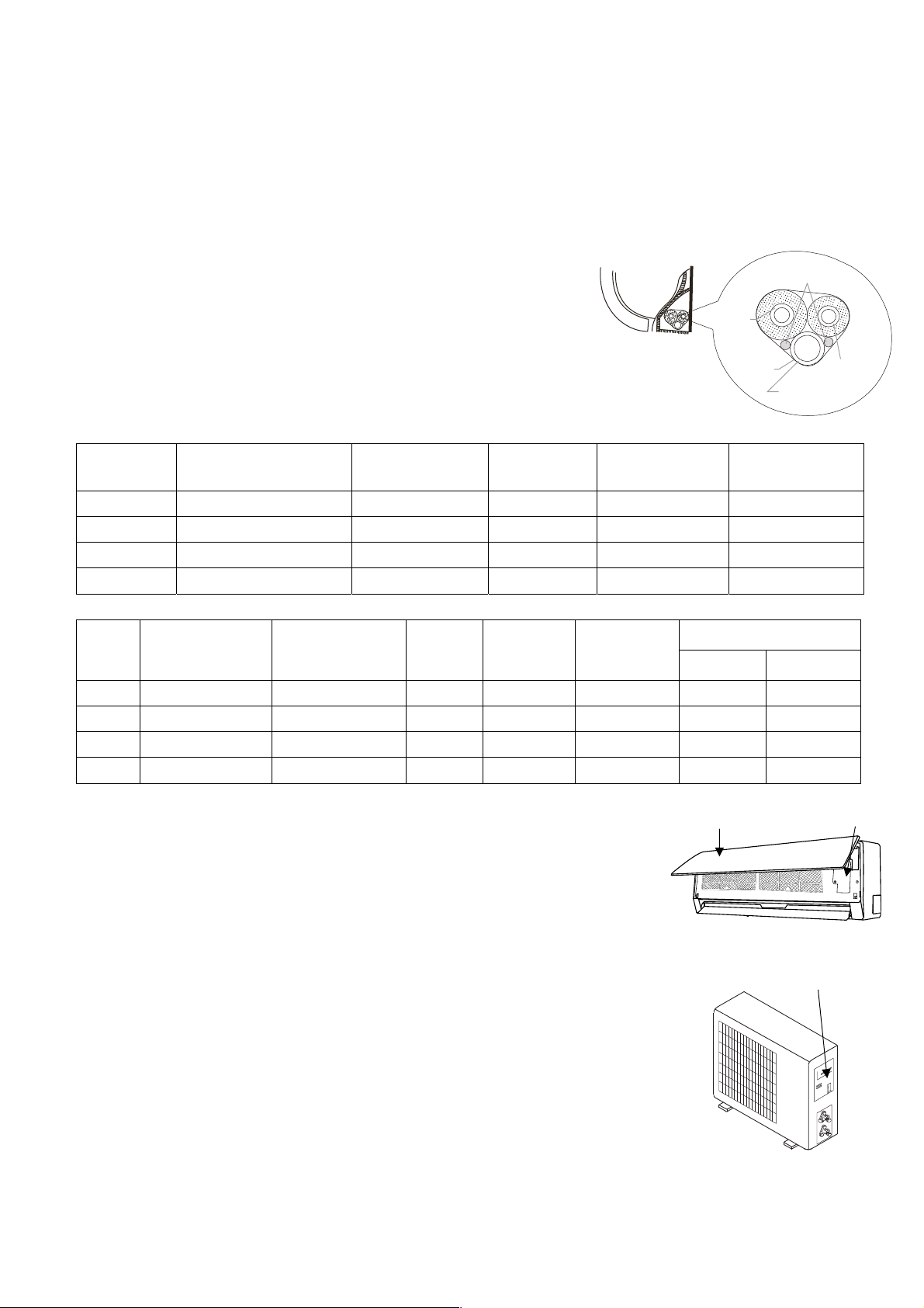
Montaggio del giunto di scolo.
Inserire la guarnizione nel gomito dello scolo, quindi inserire il giunto dello scolo nel foro basso della vaschetta dell'unità
esterna quindi ruotare di 90° per fissarlo saldamente. Collegare il giunto con il prolungamento del tubo di scolo (comprato a
parte), nel caso che l'unità esterna subisca perdite d’acqua durante il riscaldamento.
Avvolgimento delle tubazioni
Avvolgere le tubazioni dello scarico e dei cavi elettrici come mostrato nella figura a lato.
Poiché la condensa che si forma durante il funzionamento viene raccolta nell’apposita bacinella, evitare di ostruirla.
AVVERTENZE
● Connettere prima l’unità interna e poi l’unità esterna e fissare saldamente le
Unità interna
Cavi connessione
interna esterna
tubazioni.
● Non lasciare che le tubazioni escano dal retro dell’unità interna.
● Fare attenzione che lo scarico non sia allentato.
tubo
gas c on
isolamento
● Assicurarsi che le condutture ausiliarie siano state isolate.
● Assicurarsi che lo scarico defluisca correttamente. Fissare lo scarico alle
altre tubazioni.
guaina
tubo liquido
con isolamento
tubo di drenaggio
● Evitare che i cavi di alimentazione vengano a contatto con le tubazioni.
Modelli
1 x 1 DC
INVERTER
2600 W
3500 W
5300 W
7000 W
Max. lunghezza tubazioni
con carica refrigerante
standard (m)
5 15 10 20 Φ6,35/Φ9,52
5 20 10 20 Φ6,35/Φ9,52
5 25 10 20 Φ6,35/Φ12,7
5 25 10 50 Φ6,35/Φ16
Max. lunghezza
tubazioni ammissibile
(m)
Max. dislivello
ammissibile (m)
Quantità refrigerante
addizionale (g/m)
Φliquido/Φgas
Modelli
esterna
(Multi)
1 x 2
1 x 3
1 x 4
1 x 5
Max. lunghezza
tubazioni con carica
refrigerante standard
(m)
10 20 20 5 20
30 20 60 10 20
40 20 70 10 20
50 25 80 7.5 22
Max. lunghezza
tubazioni tra esterna
e più lontana interna
ammissibile (m)
Lunghezza
totale delle
tubazioni
Max. dislivello
tra internainterna (m)
Q.tà refrigerante
addizionale (g/m)
Connessioni elettriche
Collegare il cavo all'unità interna
1. Il cavo di collegamento dell'unità interna ed esterna dovrebbe essere di tipo H07RN-F.
2. Alzare il pannello dell'unità interna e rimuovere la vite, quindi rimuovere il coperchio.
3. Collegare i cavi secondo i loro contrassegni ai terminali.
4. Avvolgere i cavi dei terminali con nastro isolante, in modo che non si tocchino a
vicenda.
Collegare il cavo all'unità esterna
1. Rimuovere il coperchio dell'unità esterna.
2. Collegare i cavi terminali in base ai numeri presenti sulla morsettiera dell’unità.
3. Collegare l’alimentazione all’unità esterna usando un cavo di tipo H07RN-F
3. Per impedire l'ingresso di acqua isolare bene i cavi.
4. Fissare i cavi in modo che non vengano in contatto con parti elettriche o in metallo.
Attacchi unità interne
Unità Interna
2600 W
3500 W
5300 W
7000 W
Pannello frontale Morsettiera
Φliquido/Φgas
Φ6,35/Φ9,52
Φ6,35/Φ9,52
Φ6,35/Φ12,7
Φ6,35/Φ16
Unità interna
Portello di accesso morsettiera
13
Unità interna

Specifiche Cavi
T
TIER
T
TIER
T
TRIC
T
TIER
T
TIER
T
TRIC
Modelli (W)
1 x 1 DC INV.
Cavo collegamento alimentazione Cavo collegamento interna-esterna Alimentazione
Sezione Sezione
principale
Capacità interruttore
del circuito (A)
2600 W, 3500 W 3 x 1.5 mm² 4 x 0,75 mm² All'esterna 20 A (240V)
5300 W, 7000 W 3 x 1.5 mm² 4 x 0,75 mm² All'esterna 25 A (240V)
Unità interne
(W)
Cavo collegamento
-
Unità esterne
Sezione Sezione
²
²
²
²
Cavo collegamento
²
²
²
²
Alimentazione
principale
All'esterna
Capacità
interruttore del
circuito (A)
Schemi di cablaggio
1 x 1 DC INVERTER (Mod. 2600 W, 3500 W) 1 x 1 DC INVERTER Mod. 5300 W, 7000 W
MORSE
UNITÀ ESTERNA
BU
BK
BN
A
MORSE
UNITÀ INTERNA
BU
BK
BN
A
MORSE
UNITÀ ESTERNA
BU
BK
BN
A
MORSE
UNITÀ INTERNA
BU
BK
BN
A
L N
ALIMENTAZIONE
ELE
A
L N
ALIMENTAZIONE
ELE
A
14

Installazione delle tubazioni per il refrigerante
1. Cartellatura
La causa principale di perdite di refrigerante è dovuta ad un difetto nella cartellatura.
Effettuare le cartelle in modo corretto rispettando le seguenti indicazioni:
A: Tagliare i tubi ed il cavo.
1. Utilizzare tubi con misure adeguate all'unità installata.
2. Misurare la distanza fra l'unità interna ed esterna.
3. Tagliare i tubi ad una lunghezza leggermente maggiore della distanza misurata.
4. Tagliare il cavo 1.5 m più lungo della lunghezza del tubo.
B: Rimozione della bava
1. Rimuovere completamente tutte le bave dalla sezione trasversale del tubo.
2. La lavorazione deve essere eseguita con l’estremità da lavorare verso il basso in modo che le bave non cadano dentro al
tubo.
C: Collocazione del dado
Rimuovere i dadi fissati sull’unità interna ed esterna, infilarli sul tubo ed eseguire la cartellatura e la rimozione delle bave
come precedentemente indicato. (Non è possibile fissarli dopo la cartellatura).
15
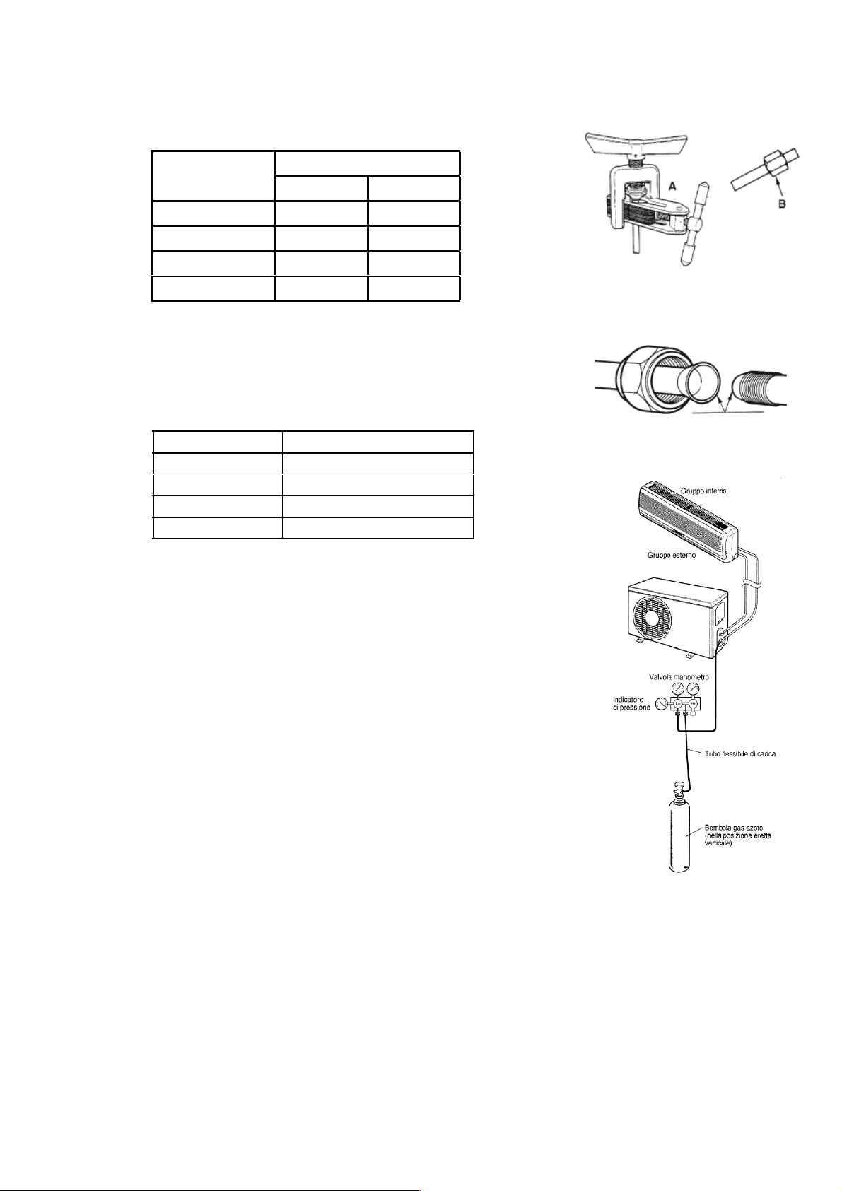
D: Cartellatura
.
Fissare saldamente il tubo di rame con un dado della dimensione indicata nella
tabella.
A(mm)
Diam. Est. (mm)
Max. Min
Φ 6,35
Φ 9,52
Φ 12,7
Φ 16
Fissaggio del tubo di collegamento
● Allineare i tubi.
● Stringere sufficientemente il dado e stringerlo con due chiavi come indicato in figura
PRECAUZIONI
● Una coppia di torsione eccessiva può rompere il dado.
Diam. Est. (mm ) Coppiadi torsione(N.m)
Φ 6,35
Φ 9,52
Φ 12,7
Φ 16
Eliminazione dell'aria
L'aria e l'umidità nel sistema refrigerante possono causare effetti indesiderati come
indicato qui sotto:
● Aumento della pressione nel sistema.
● Aumento della corrente assorbita.
● Diminuzione dell’efficienza del refrigerante.
● L'umidità nel circuito refrigerante può congelare ed ostruire la tubazione capillare.
● L'acqua può corrodere le parti del sistema di refrigerazione.
Di conseguenza il gruppo interno e i tubi posti tra gruppo interno ed esterno devono
essere collaudati per perdite e spurgati per rimuovere elementi non condensanti e
umidità dal sistema.
Eliminazione dell'aria con la pompa del vuoto
Preparazione
Verificare che ciascun tubo (sia i tubi laterali del gas che del liquido) tra gruppo
interno e gruppo esterno siano stati collegati nel modo corretto e che tutti i cablaggi
necessari al collaudo siano stati effettuati. Rimuovere i cappucci delle valvole di
servizio sia dai lati gas che liquido sul gruppo esterno. Prendere nota del fatto che a
questo punto entrambi le valvole del gas e del liquido rimangono chiuse.
1,3 0,7
1,6 1
1,8 1
2 1
15 ~ 20
31 ~ 35
50 ~ 55
60 ~ 65
Tubo
16

● Lunghezza del tubo e relativa quantità di refrigerante, per una corretta carica
verifica re il valore di surriscaldamento. I valori della tabella sono indicativi.
● Quando si cambia posto all’unità, realizzare lo spurgo con la pompa del vuoto.
Assi curarsi che il refrigerante all’interno del condizionatore sia sempre stato liquido.
Evacuazione
Collegare l’estremità del tubo flessibile di carica alla pompa del vuoto per evacuare
le tubature dell’unità interna. Verificare che la manopola “LO” della valvola del
manometro sia aperta. Poi far funzionare la pompa del vuoto. Il tempo di
funzionamento varia a seconda della lunghezza dei tubi e della capacità della
pompa. Quando viene raggiunto il vuoto desiderato, chiudere la manopola “LO” della
valvola del manometro e fermare la pompa del vuoto.
In conclusione, usando una chiave per valvole di servizio, ruotare lo stelo della
valvola del lato del liquido in senso antiorario per aprirla completamente. Ruotare lo
stelo della valvola del lato gas in senso antiorario per aprirla completamente.
Allentare il tubo flessibile di carica collegato alla presa di servizio del lato gas per
scaricare la pressione, poi rimuovere il tubo. Rimettere il dado di copertura della
valvola gas e della presa di servizio e stringere bene con una chiave regolabile.
Questa procedura è molto importante per evitare perdite dall’impianto. Rimettere i
cappucci delle valvole di servizio sia dal lato gas che da quello liquido e stringere
bene. Questo completa la procedura di spurgo dell’aria con la pompa del vuoto,
assicurarsi quindi che tutti i tubi siano collegati in maniera corretta e che le valvole di
servizio dei lati gas e liquido siano completamente aperte.
17

9. PROVA DI FUNZIONAMENTO
Il test deve essere eseguito solo dopo aver completato l’installazione.
Si prega di controllare i seguenti punti prima di eseguire il test.
Unità interna ed esterna devono essere installate correttamente.
Tubazioni e cavi elettrici devono essere collegati correttamente.
Test di pressione delle tubazioni.
Lo scarico condensa funziona regolarmente.
L’isolamento termico è stato eseguito correttamente.
La messa a terra è stata eseguita correttamente.
La lunghezza delle tubazioni e la carica di refrigerante sono state controllate.
La tensione di alimentazione corrisponde a quella di progetto per il condizionatore.
Ingresso ed uscita dell’aria delle unità interne ed esterne non sono ostruite.
Le valvole lato gas e lato liquido sono aperte.
Il condizionatore è stato pre-riscaldato dando tensione.
♦ Test operation
■ Impostare con il telecomando il condizionatore in modalità raffreddamento, e controllare i seguenti punti come indicato
nella parte d’uso di questo manuale. Se accade qualche malfunzionamento, risolverlo servendosi delle indicazioni del
capitolo “MALFUNZIONAMENTI” di questo manuale.
1) Unità interna
a) Verificare se accensione e spegnimento dal telecomando avvengono correttamente.
b) Verificare se i tasti del controllo remoto sono tutti operativi.
c) Verificare se i deflettori od alette si muovono regolarmente.
d) Verificare se la temperatura interna è regolata correttamente.
e) Verificare se gli indicatori sul ricevitore funzionano.
f) Verificare se il tasto manuale funziona correttamente.
g) Verificare se lo scarico condensa avviene con regolarità.
h) Verificare se ci sono vibrazione o rumori strani durante l’operazione.
j) Verificare se la capacità di riscaldamento è adeguata.
2) Unità esterna
a) Verificare la presenza di eventuali rumori o vibrazioni fuori norma.
b) Verificare se ci sono perdite di gas refrigerante.
CAUTELA
La funzione di protezione del condizionatore impedisce l’accensione immediata dello stesso dopo averlo
spento. Il condizionatore all’intervento della protezione potrà essere riavviato dopo circa 3 minuti dal suo
spegnimento.
18

RU
РУКОВОДСТВО ПО ЭКСПЛУАТАЦИИ
Кондиционер Системы Сплит
Серия Winner
МОДЕЛИ:
Пожалуйста, внимательно изучите данное руководство перед началом работы
Designed by Cooper&Hunter International Corporation, Oregon, USA
www.cooperandhunter.com
CH-S09FTX5
CH-S12FTX5
CH-S18FTX5
CH-S24FTX5

Меры предосторожности
Пожалуйста, прочитайте следующее прежде, чем использовать оборудование!
ПРЕДУПРЕЖДЕНИЕ
При появлении запаха
★
дыма немедленно
обесточьте кондиционер
и свяжитесь с сервисным
центром
Если этого не сделать,
оборудование может выйти
из строя, случиться короткое
замыкание или привести к
пожару
Используйте кабель
★
питания, соответствующий
требованиям электро- и
пожаробезопасности
Не касайтесь
★
оборудования
мокрыми руками
Это может привести к
поражению
электрическим током
Если вы планируете не
★
использовать
кондиционер в течение
долгого времени,
обесточьте оборудование.
Предохраняйте от
★
повреждений
электрический кабель и
кабель межблочной
связи. Если изоляция
кабеля повреждена,
обратитесь в сервисный
центр, чтобы заменить его.
Запрещается
использовать
оборудование с
поврежденным кабелем
Не используйте
★
поврежденный кабель
электропитания
или кабель,
не соответствующий
требованиям электрои пожаробезопасности
Запрещается использовать
удлинители
Перед чисткой
★
кондиционера,
пожалуйста, обесточьте
его
˜°˛˝˙ˆˇ°˘
питание
Несоблюдение этого
правила может привести к
поражению электрическим
током
Может случиться так, что в
блоке будет собираться
пыль, которая вызовет
перегрев, короткое
замыкание или пожар
Источник питания должен
★
соответствовать
спецификации
кондиционера и
оборудован автоматом
токовой защиты
соответствующего
номинала. Не снимайте и
не подавайте питание на
кондиционер
слишком часто
1
В противном случае может
произойти пожар из-за
перегрева кабеля питания
Если напряжение
★
электросети слишком
высокое, это может
привести к повреждению
оборудования. Если
напряжение сети слишком
низкое, компрессор
начнет сильно
вибрировать, и это может
привести к его
повреждению.
Также это может привести
к тому, что компрессор и
электрические
компоненты системы
не будут
функционировать

Меры предосторожности
Убедитесь,
★
что оборудование
надежно заземлено
Использование
незаземленного
оборудования может
привести к поражению
электрическим током
Не оставляйте окна и
★
двери открытыми
длительное время во
время использования
кондиционера
Для собственной
★
безопасности отключайте
кондиционер от источника
питания перед
обслуживанием, ремонтом
и чисткой, а также если
планируете не
использовать его
длительное время
Накапливающаяся пыль
может привести к пожару
Не блокируйте воздушные
★
потоки на выходе и входе
оборудования.
Устанавливайте
★
наиболее подходящую
температуру
Установить темп.
в помещении на
5 °С ниже, чем на
улице
Это поможет снизить
расход электроэнергии
Храните горючие
★
материалы вдали от
кондиционера. Не
используйте открытый
огонь вблизи
оборудования
ГАЗ
Это будет влиять на
эффективность работы
кондиционера
Устанавливайте
★
наружный блок на
надежный фундамент
или крепление
Ненадежно установленный
блок может упасть и
нанести травму
Это будет влиять на
эффективность работы
оборудования и может
привести к неисправности
Ничего не ставьте и
★
не вставайте на
наружный блок
Это может упасть и
нанести травму
2
Это может привести к
пожару или взрыву
Не ремонтируйте
★
кондиционер
самостоятельно
Это может привести к
пожару или поражению
электрическим током.
Обращайтесь в
авторизованные
сервисные центры
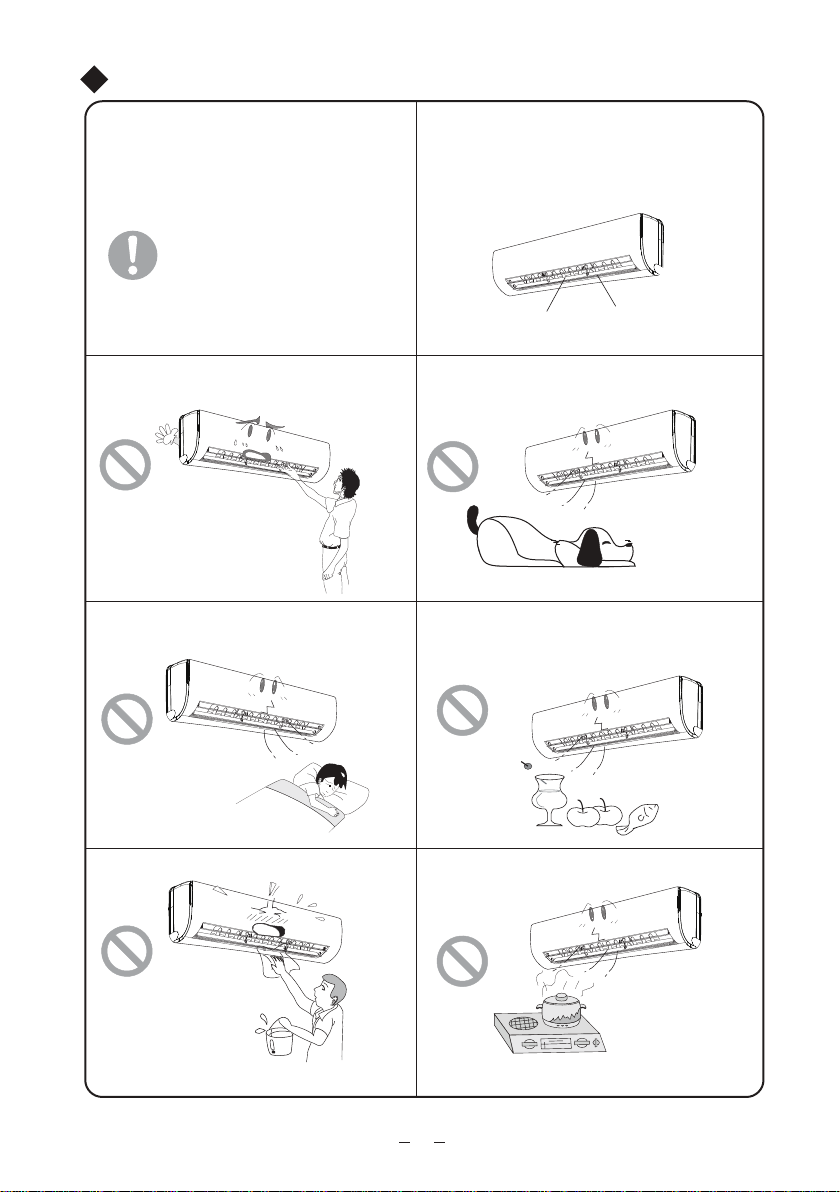
Меры предосторожности
Не используйте кабель со скрутками
★
и поврежденный кабель. Если кабель
поврежден, пожалуйста, свяжитесь с
сервисным центром для его замены
Не суйте руки и посторонние предметы
в отверстия забора и подачи воздуха
Это может привести
к травме или повреждению
оборудования
Не находитесь под струей холодного
воздуха длительное время.
Для изменения направления
★
горизонтального воздушного потока
используйте пульт дистанционного
управления
Вертикальные
жалюзи
Не помещайте животных и растения под
★★★★★★
струю воздуха из кондиционера.
Это может нанести им вред
Не используйте кондиционер не по
★★★★
назначению, например, для охлаждения
продуктов питания или сушки одежды
Горизонтальные
жалюзи
Это может нанести вред
вашему здоровью
Не брызгайте водой на кондиционер
Это может привести к повреждению или
поражению электрическим током
Не используйте открытый огонь рядом
★★
с кондиционером
Это может привести к отравлению угарным
газом
3
 Loading...