

Page 1

TOUCHSCREEN REPEATER PANEL
INSTALLATION MANUAL
CTPR3000
Cooper Fire Systems
Security House,
Vantage Point Business Village
Mitcheldean
Gloucester
GL17 0SZ
United Kingdom
TEL: +44(0)1594 541900
FAX: +44(0)1594 541910
Page 2

Introduction to the Manual
This manual provides information on the installation, operation and
maintenance of the Panel System.
NOTICE
The operating system of the panel may be revised as a result of
enhancements to the system software or hardware. Revisions to this
manual will be issued and supplied on request and should be logged
in the table supplied on the contents page.
Introduction
Page 3

Contents Page
1.0 System Design & Installation
Introduction 7
Technical Specification 8
Cable and Wiring 10
Installation 11
Fixing details 12
External Connections 13
Networking 14
2.0 Commissioning the Panel
Commissioning 16
3.0 Panel Controls and Indicators
Touch Screen Display 20
Panel Operation 21
Public Access Level 1 22
Evacuate (Access Level 2) 23
Silence Alarms 24
Mute Buzzer 25
Pre-Alarms 26
Panel Controls and Indicators 19
Faults 27
Enable / Disable 27
Print (Function not availible) 28
Lamp Test 29
View Events 30
Send Log to PC 31
Erase Log 32
System Details 33
Load Logo from PC 34
Repeater Mode 35
Printer Settings 36
Change Panel Number 38
Number of Panels in Network 39
Change Date/Time 40
Change Panel Text 41
Change Passcode 42
Relay Control 43
Programable Input 44
Network 45
Language 46
Network Protocol 47
Power Supply 48
Password Protection 49
4.0 Appendix
System Wiring 51
Contents
Document Drg Ref PR203-68-532-01
Page 4

Contents
Page 5

Contents
Contents Page
Page 6

System Installation and Design
Section 1
6
Page 7

Introduction
Analogue Touchscreen Repeater Panel CTPR3000
The CTPR3000 fire detection repeater panel provides sophisticated ‘touch
screen’ functionality yet achieves a simple end-user interface operation
within a compact panel design. The CTPR3000 is designed to work with
Cooper Analogue Addressable Fire alarm Control Panels as a network
repeater. It is fully compliant with the statutory requirement of EN60950
(LVD) and EN50130 (EMC) and includes an integral monitor PSU compliant
with the latest requirements of EN54 pt4 together with a wide range of user
controllable functions; make the panel suitable for a wide range of projects.
The Cooper repeater panel is easy to install and commission all text is
transmitted via the network and is automatically updated and as the
following features
• Plug and play. All information is downloading through the network
• Touch Screen Display
• Integrated Network capability allows networking with Cooper latest range of analogue
addressable Fire Alarm Control Panels
• Multi language capability
• 2 programmable Auxiliary relays
• 24 Volts 500ma output
• Programmable input is available
• External Printer outputs
• Up to 1000 event log
• Optional local and external PSU
• PSU approved to EN54 pt4
• Utilises 2 core cables and up to 125 repeaters can be connected to the network
• Programmable as an active or Passive Repeater can be power locally or external 24
volts power supply
7
Page 8

Technical Specification
Power Specification
Mains Fuse : 1.6A Slow Blow
Nominal Voltage : 230 Vac + 10%, -15%
Nominal Current : 75mA
The Panel is protected by an internal thermal device, this requires no maintenance
Batteries
Number of Batteries : 2
Manufacturer: :YSP12-7
Capacity : 7 Ah
Battery Fuse : 4A Quick Blow (F4)
Maximum battery current; : 3.5 Amps
Standby current (mA) : 100 (1 loop )
Inputs
Programmable Input (TB10)
Link input to activate
Outputs
Programable Auxiliary Relays
The programable auxiliary relays provide fused volt free change over contacts. These
contacts are not monitored.
Max Load : 24 Volts 1 Amp
Fuse (PTC4) : 1.1 Amps polyswitch
Programable Fault Relays
The programable fault relays provide fused volt free change over contacts. These
contacts are not monitored.
Max Load : 24 Volts 1 Amp
Fuse (PTC3) : 1.1 Amps polyswitch
24V Input Supply
Nominal Voltage : 24 Volts ±10%
Fuse (PTC1) : 1.1 Amps polyswitch
Maximum current : 800 mA
Any power taken from the alarm system will effect the standby duration
24V Output Supply
Nominal Voltage : 24 Volts ±10%
Fuse (PTC2) : 1.1 Amps polyswitch
Maximum current : 500 mA
(TB8)
(TB7)
(TB1)
(TB2)
8
Page 9

Mechanical Specification
Weight including batteries : 9 Kg
Weight excluding batteries : 4 Kg
Dimensions (Standard batteries) : 395mm(L) x 270mm(H) x 115mm(D)
Type of Material (backbox) : Mild Steel (Power Coated)
Type of Material (Facia) : PC/ABS
Flammability Rating : UL 94 V0
Total Number of knockouts : 11
Diameter of Knock out : 20mm
TERMINAL BLOCKS : DO NOT USE EXCESSIVE FORCE WHEN TIGHTENING THE SCREWS ON
THE TERMINAL BLOCK
Technical Specification
9
Page 10
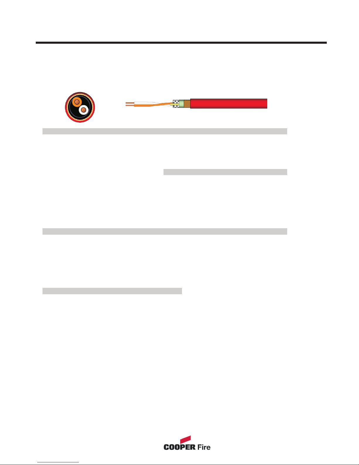
Cable & Wiring
Only the cable types listed below are allowable for loop connections.
DRAKA Cables (Part Number 910234)
Technical Specification
When choosing your preferred cable type, you must take note of the following cable and
wiring requirements.
1. The cable must be 2 core screened with an over sheath.
2. Maximum loop length with any of the above cables is 1KM
3. Multicore cable should not be used for detector wiring.
4. The screen or drain wire of the network cable should not be considered as a
safety earth.
5. Screen continuity must be maintained throughout the entire network circuit
including at each junction point.
6. Where the network cable passes between buildings, screen continuity should not
be maintained from building to building. A booster device must however be used
irrespective of cable length and should be fitted at a suitable point in the link
between buildings. The cable screen should be connected to the earth of one
panel in each building.
10
Cabling Application Applicable Standards
Circuit integrity Structured Wiring
Alarm/Lighting Cable Part Number 910234
Patent Protected Design
ISO/IEC 11801:95
EN 50173:95
Fire Propagation Test : UL 1581 VW1;
IEC60332.3;
Cct Integrity tests: IEC 60331; BS5839: 2002
Cable construction
Conductor
Insulator Material
Number of Twisted Pairs
Glass Tape
Screen Material
Braid
Sheath Material
Bare Cu
Wire
PE/Sil Rbr
1
Mica
Ali/Mylar
TCWB
OHLS
Outside Diameter of Conductor
Outside Diameter of Insulation
Outside Diameter of Sheath
Weight OHLS
Sheath Colour (OEM Specified)
Sheath Printing (up to 24
characters)
0.65 mm
1.70 mm
5.3 mm
15.8 kg/km
Various
Batch No. &
Metre marking
Cable Properties Electrical Characteristics @ 20 ºC
Min. Installation Bend Radius
Min. Installed Bending Radius
Max. Installation Tension
Max. Installed Tension
InstTemp. Range Installed
Operating Temp. Range
8 x Dia
4 x Dia
50N
Zero
0 to 0ºC
-20 to 60ºC
Return Loss Rl
Characteristic impedance @
10MHz
DC Conductor Loop Resistance
Max. Resistance unbalance
Nominal Velocity of Propagation
Insulation Resistance (500V)
300/500v rated
>IEC dB
100±5Ù
30 Ù/100m
?2%
57%
?5000
MÙ.km
Fire tests BS 5839: 2002 & IEC60331
Continued Data Operation @ 950°
Smoke test
Approvals
>3 Hours
passed
passed
Page 11

The panel should be installed in a clean, dry, reasonably well ventilated place, and not in
direct sunlight. Temperatures in excess of +45°C and below -10°C may cause problems, if
in doubt consult . The panel should be located away from any potential
hazard, in a position where it is readily accessible to authorised staff, and the fire services,
ideally on the perimeter of a building near a permanent entrance. Mount the panel to the
wall using the drill template provided. Do not drill through the panel to the wall as dust will
contaminate the circuitry.
Installation Guide
! Never carry out insulation tests on cables connected to electronic equipment.
! DO NOT OVER TIGHTEN TERMINAL CONNECTOR SCREWS
! Always use the correct type of cables specifically designed for the operation of fire
detection and alarm circuits.
! Always adhere to volt drop limitation when sizing cables
! Always observe polarity throughout. Non colour coded conductors should be
permanently identified.
!
!
Technical Support
Screen continuity must be maintained throughout the entire network.
The screen should be earthed at the connection point provided at the Panel and not
at any other point.
Care must be taken to avoid connecting the screen to the earthed body of any
metal devices, enclosures or cable containment. The screen or drain wire of the
network cables should not be considered as safety earth and therefore should not
be connected to terminals marked with the earth symbol, except at the panel, and
should not be insulated with green and yellow sleeving.
Installation
11
Page 12
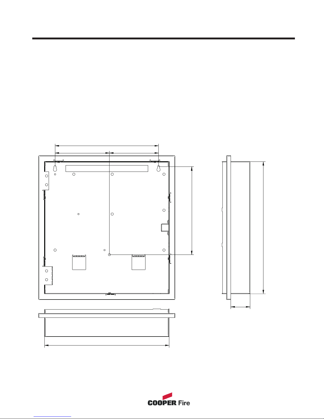
Fixing details
Read all the installation instructions before commencing with the installation. The
installation of this panel must be carried out by a suitably qualified /trained person. The
installation must comply with IEE wiring regulations and with BS5839 part 1 2002
The electronic components within the fire panel are Static Sensitive. Do not
touch the electronics directly.
Mounting the Backbox
The Panel can be surface mounted and recessed . To surface mount; drill three holes
and fix the backbox to the wall using suitable screw fixings.
Installing Cabling
Once the backbox is mounted the next stage is to install the power and loop cables and
fit the glands.
270.00
128.20141.80
229.80
345.00
50.00
325.00
12
All Dimensions in MM
Page 13

External Connections
Mains Supply
The mains supply should be installed in accordance with the current edition of the IEE
wiring regulations. Connection to the mains supply must be via an isolating device (e.g.
an isolating fuse) reserved solely for the fire alarm system. The cover should be
coloured red and labelled “FIRE ALARM - DO NOT SWITCH OFF”. The isolating
protective device should be secure from unauthorised operation and ideally installed in a
securely closed box with a breakable cover.
An additional warning label should be provided, depending on whether:-
a) The isolating protective device is fed from the live side of the main isolating
device in which case the label on the isolating protective device, should read
in addition - “WARNING: THIS SUPPLY REMAINS ALIVE WHEN THE MAIN
SWITCH IS TURNED OFF”. A further label should be placed on the main
isolating device reading “WARNING: THE FIRE ALARM SUPPLY REMAINS
LIVE WHEN THIS SWITCH IS TURNED OFF.
Or
b) If the isolating protective device is fed from the dead side of the main
isolating device, a label should be fixed to the main isolating device reading
“WARNING: THIS SWITCH ALSO CONTROLS THE SUPPLY TO THE FIRE
ALARM SYSTEM”.
Distributed Power Supplies
The above also applies to any distributed power supply (i.e. mains connections for
Repeater Panels , Sounders Controller Units, etc.)
13
Page 14

Networking
Up to One Hundred & Twenty Six Panels or repeaters can be networked together to
operate as a single networked system. To achieve this each panel must be fitted with a
network card (Optional Extra)
When operating as a networked system all fire and fault event information is displayed
at every panel, silencing and resetting of alarms can also be carried out from any panel
on a networked system if panels are suitably configured.
Networked panels are connected using a loop topology as illustrated.
Networked panels can be used as active repeaters, alternatively a low cost passive
repeater is available.
This can either be connected a loop of an individual panel or it can be connected to the
network.
The recommended network cable for the network connection between panels is an
enhanced Firetuf cable Manufactured by Draka cables (part number )910234.
Screen continuity must be maintained throughout the entire network circuit including at
each junction point. The screen should only be earthed at the connection point provided
at the first panel and not at any other point. The screen or drain wire of the network
cable should not be considered as a safety earth and therefore should not be connected
to terminals marked with the earth symbol, except at the panel, and should not be
insulated with green and yellow sleeving
Where the network cable passes between buildings, screen continuity should not be
maintained from building to building. A booster device must however be used
irrespective of cable length and should be fitted at a suitable point in the link between
buildings. The cable screen should be connected to the earth of one panel in each
building. 102 S terminator should be fitted at the beginning and the end of the network.
If the distance in the network exceeds 1KM the booster should be used. The booster
requires 24V local supply, which can be connected to nearest Addressable Panel
4.1.3 Acceptable Cable length.
Based on the above cable, the maximum acceptable length between signal boosters is 1000 Metres.
This distance can only be achieved when the above cable is used, Cooper lighting and security does not
recommend the use of other network cables.
Once the maximum cable length has been reached, a booster must be fitted which then allows a further
length of the same distance (1000 Metres for the recommended cable).
A maximum of 5 network boosters can be used
N.B. Repeater control panels do not act as boosters, therefore the location of such panels is irrelevant
when calculating cable lengths and the requirement for booster devices.
For convenience when using 24V boosters (see following) it may be desirable to house the booster near
to an repeater control panel to derive a convenient power supply.
14
Page 15
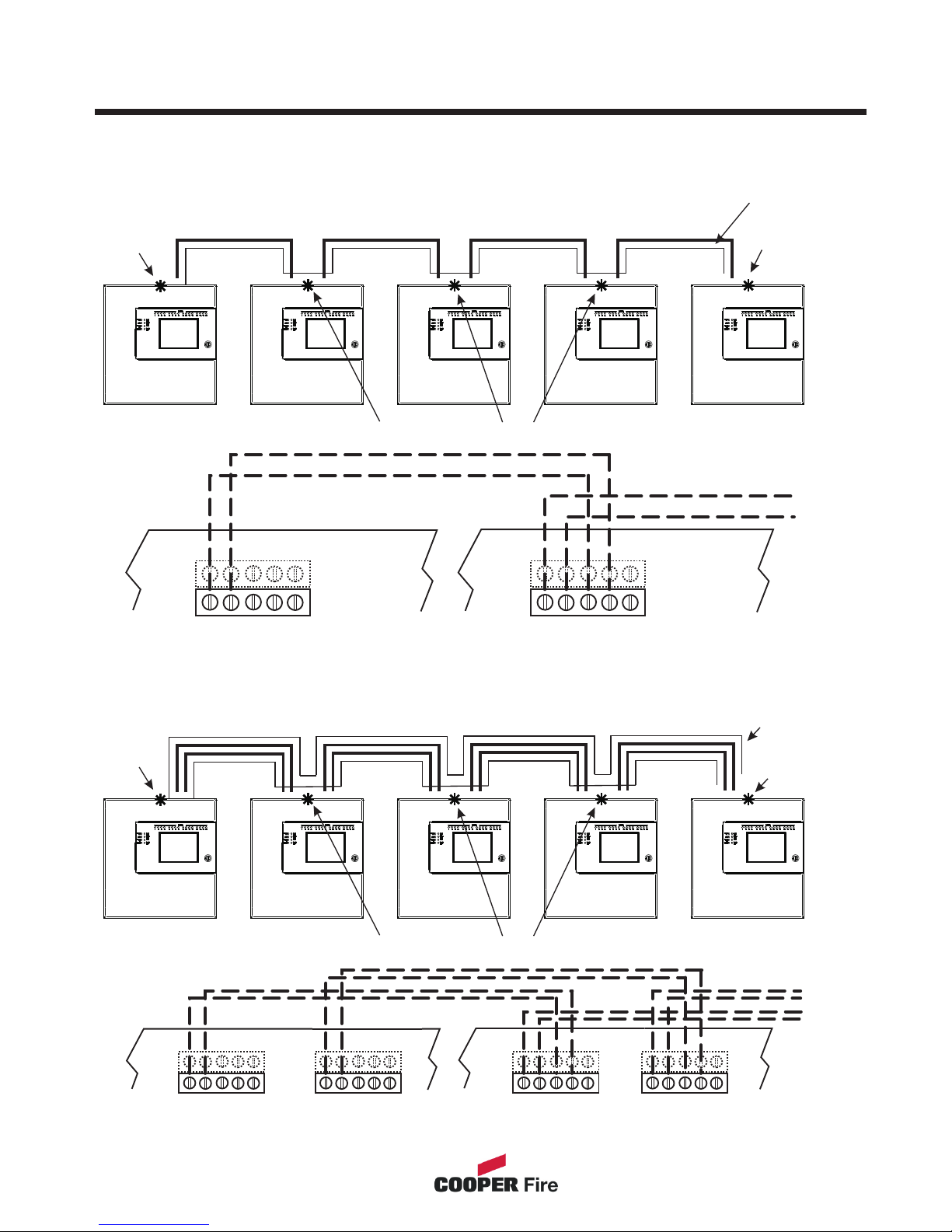
Networking
Network Cable
2 Cores
Network 1
Cable
Network 1
Cable
Network 1
Cable
Network 1
Cable
Terminator
fitted
Terminator
fitted
Terminator not required
Terminator not required
Wiring Diagram
Next
Next
Terminator
fitted
Terminator
fitted
Screened
cable
Screened
cable
Network Cable
2 Cores
Network Cable
2 Cores
Network Cable
2 Cores
Please Note: Cooper Network cards are fitted with loop terminators as standard please cut if not required.
Daisy chain configuration
Single Network Card
Redundant Network
TOP
TOP TOP
B
B B
X
X X
E
E E
Y
Y Y
A
A A
TOP
TOP
B
B
X
X
E
E
Repeater Panel
Network 1 Terminal
on main PCB
Repeater Panel
Network 1 Terminal
on main PCB
Repeater Panel
Network 2 Terminal
on main PCB
Y
Y
A
A
Main Panel
Network Terminal
on main PCB
Main Panel
Network 1 Terminal
on main PCB
Main Panel
Network 2 Terminal
on main PCB
15
Repeater Panel
Repeater Panel
Panel 1
Panel 1
Panel 2
Panel 2
Panel 3
Panel 3
Panel 4
Panel 4
Network 2
Cable
Network 2
Cable
Network 2
Cable
Network 2
Cable
Page 16

Commissioning
Section 2
16
Page 17

The Cooper Repeater is a plug & play technology where downloading of text information
through a PC is not required as the text information is downloaded via the network.
1. Supply the network address (pagexxxxxxxxxxx)
2. Select the repeater mode information (page xxxxxxxx)
3. Program the relays output and programable input if required (page
xxxxxxxxxxxxxxxxx)
4. Select the power supply option (page xxxxxxxxx)
Commissioning
17
Page 18

Panel Controls & Indicators
Section 3
18
Page 19
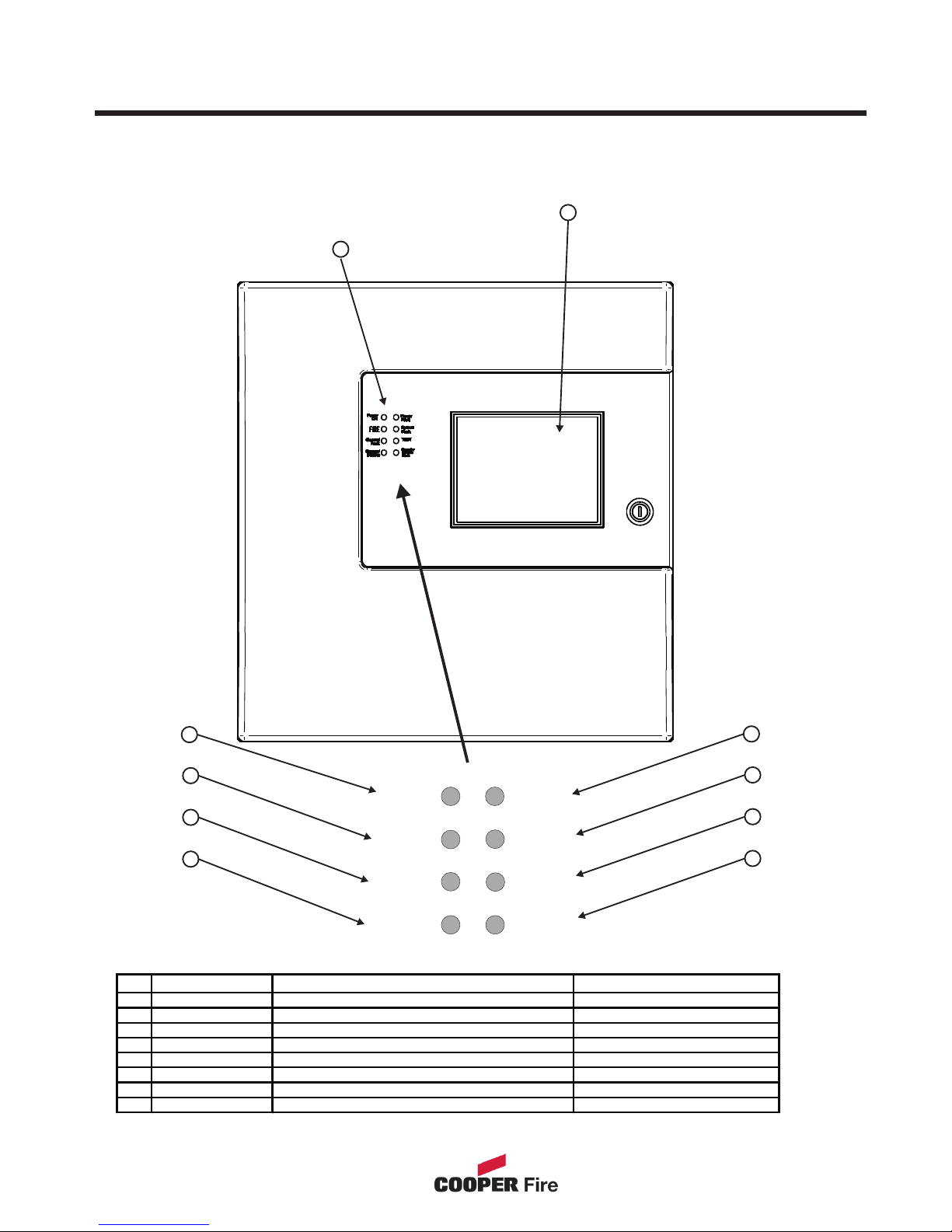
1. System LED’s
2. Zonal LED’s
3. Touch Screen Display
Panel Controls & Indicators
1
2
3
4
5
6
7
8
LED Name Function Action
1 Power On Shows Panel is On Check Indicator is Illuminated
2 Fire Indicators Panel has Detected a Fire Impliment Fire Act ion Procedure
3 General Fault Monitors Devices for Faults e.g. Smoke detectors/ Sounders Report to System Supervisor
4 General Disable Monitors Fire Panel for Faults Report Fault to Service Dept
5 Power Fault Monitor Internal Battery Charger Report Fault to Service Dept
6 System Fault Monitors Fire Panel for Faults Report Fault to Service Dept
7 Test Supervisor/Engineer is Testing the Systems Report to Syst em Supervisor
8 Sounder Indicates the Sounder Status Check with System Supervisor
3
1
General
Fault
FIRE
TEST
General
Disable
Sounder
Disable
Fault
Power
ON
System
Fault
Power
Fault
19
Page 20

Touch Screen Display
The Touch Screen is a multi-function display consisting 320x240 dots featuring high
intensity backlighting. In normal operation, the display indicates as above with the
backlighting off.
During an event on the system the display shows the FIRST EVENT and LAST
EVENT plus other events as space allows.
The last 2 lines are normally used to display the total number of events, but they are
also used for scrolling fire conditions, faults, pre alarms or disabled devices
independently or for displaying a reduced menu when in fire condition.
When an event occurs the Touch Screen backlighting comes on unless there is a mains
power supply fault.
Use the Touch Screen to scroll through all active events on the system by using the
SCROLL UP and SCROLL DOWN buttons (available at access level 1). You can display
the contents of the log and also view details of any fires, faults, pre-alarms,faults or
disablements.. When displaying the system menu on the Touch Screen, the last 5 lines
of the display are shown in reverse text.
Supervisor
Fires
0
Pre
Alarms 0
Faults
0
Disabled
0
Tuesday
dd-mm-yyyy
16:25.25
BST On
20
Repeater Panel
System Healthy
Page 21
Supervisor
Fires
0
Pre
Alarms 0
Faults
0
Disabled
0
Tuesday
dd-mm-yyyy
16:25.25
BST On
Panel Operation
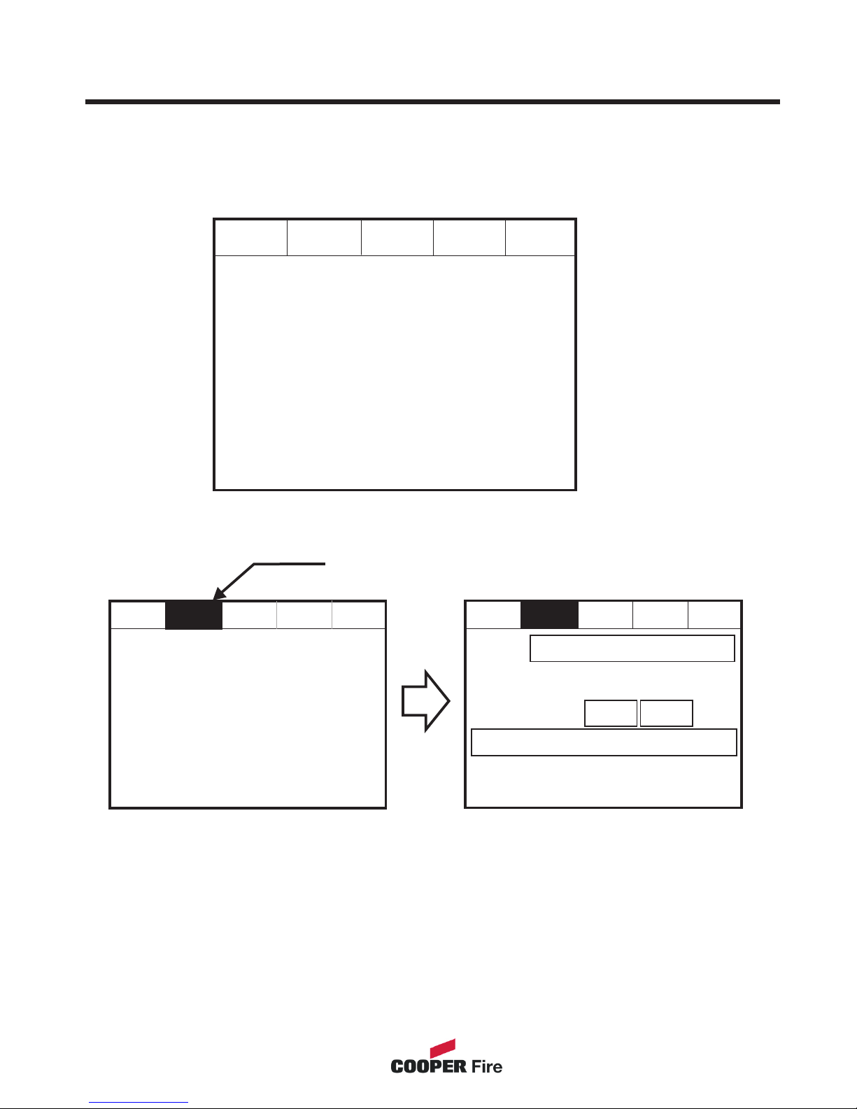
The Panel is operated via a backlit touch screen. The default fire screen is shown
below. From this screen all the panels functions can be operated. The first time you
touch the screen the backlight will illuminate the panel.
Pressing a field will highlight it and forward to the next screen as shown below.
Supervisor
Pre
Alarms 0
Faults
0
Disabled
0
Tuesday
dd-mm-yyyy
16:25.25
BST On
Fires
1
Supervisor
Pre
Alarms 0
Faults
0
Disabled
0
Tuesday
Dd-mmm-yyy
16:25.25
BST On
First Fire
Total Fires= 1
Meeting Room 1, Building 1, 1st floor
Loop: 1, Zone: 2, Type: Optical
001 FIRE! Meeting Room 1, [Optical] (Ana = 169)
Building 1, 1st floor, Panel 1, Loop1, device 4
Fires
1
Print All
Help
Touch the screen here to view details
21
Repeater Panel
System Healthy
Repeater Panel
Page 22
Repeater Panel
System Healthy
Public Access Level 1
Supervisor
Fires
0
Pre
Alarms 0
Faults
5
Disabled
/ Test
Disabled
/ Test
Tuesday
dd-mm-yyyy
16:25.25
BST On
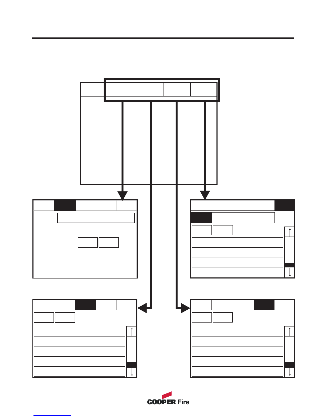
Public access level does not require an access code and allows anybody to review the
functions outlined below.
Public Access Level
Pre
Alarms 0
Faults
0
Tuesday
dd-mm-yyyy
16:25.25
BST On
First Fire
Total Fires= 1
12:26:23 Device 1, Zone 1
Lp: 1, Ad:1, Z:1, Opto/thermal, [69]
Fires
1
Print All
Help
Supervisor Supervisor
Supervisor
Supervisor
Faults
0
001 03-Jun-03 12:51 Warning! : Device1
Lp: 1, Ad: 1, Z: 1, Opto/thermal [69]
001 12:31:59 Fault! : Device1
Lp: 1, Ad: 1, Z: 1, Opto/thermal [0]
002 03-Jun-03 12:51 Warning! : Device2
Lp: 1, Ad: 2, Z: 1, Opto/thermal [69]
002 12:32:59 Fault! : Device2
Lp: 1, Ad: 2, Z: 1, Opto/thermal [69]
003 03-Jun-03 12:51 Warning! : Device3
Lp: 1, Ad: 3, Z: 1, Opto/thermal [69]
003 12:33:59 Fault! : Device3
Lp: 1, Ad: 3, Z: 1, Opto/thermal [69]
004 03-Jun-03 12:51 Warning! : Device4
Lp: 1, Ad: 4, Z: 1, Opto/thermal [69]
004 12:34:59 Fault! : Device4
Lp: 1, Ad: 4, Z: 1, Opto/thermal [69]
005 03-Jun-03 12:51 Warning! : Device5
Lp: 1, Ad: 5, Z: 1, Opto/thermal [69]
005 12:35:59 Fault! : Device5
Lp: 1, Ad: 4, Z: 1, Opto/thermal [69]
Fires
0
Print All
Help
Pre
Alarms 6
001 Device 2, Zone 1
Loop 1, Zone: 1, Type : Opto/thermal
002 Device 3, Zone 1
Loop 1, Zone: 1, Type : Opto/thermal
003 Device 4, Zone 1
Loop 1, Zone: 1, Type : Opto/thermal
004 Device 5, Zone 1
Loop 1, Zone: 1, Type : Opto/thermal
Fires
0
Show
Zones
Print All
Help
Pre
Alarms 6
Show
I/O
Fires
0
Print All
Help
Pre
Alarms 6
Faults
5
Faults
0
Show
Test Zone
Show
Addresses
Disabled
/ Test
Disabled
/ Test
Disabled
/ Test
22
Page 23
Evacuate (Access Level 2)
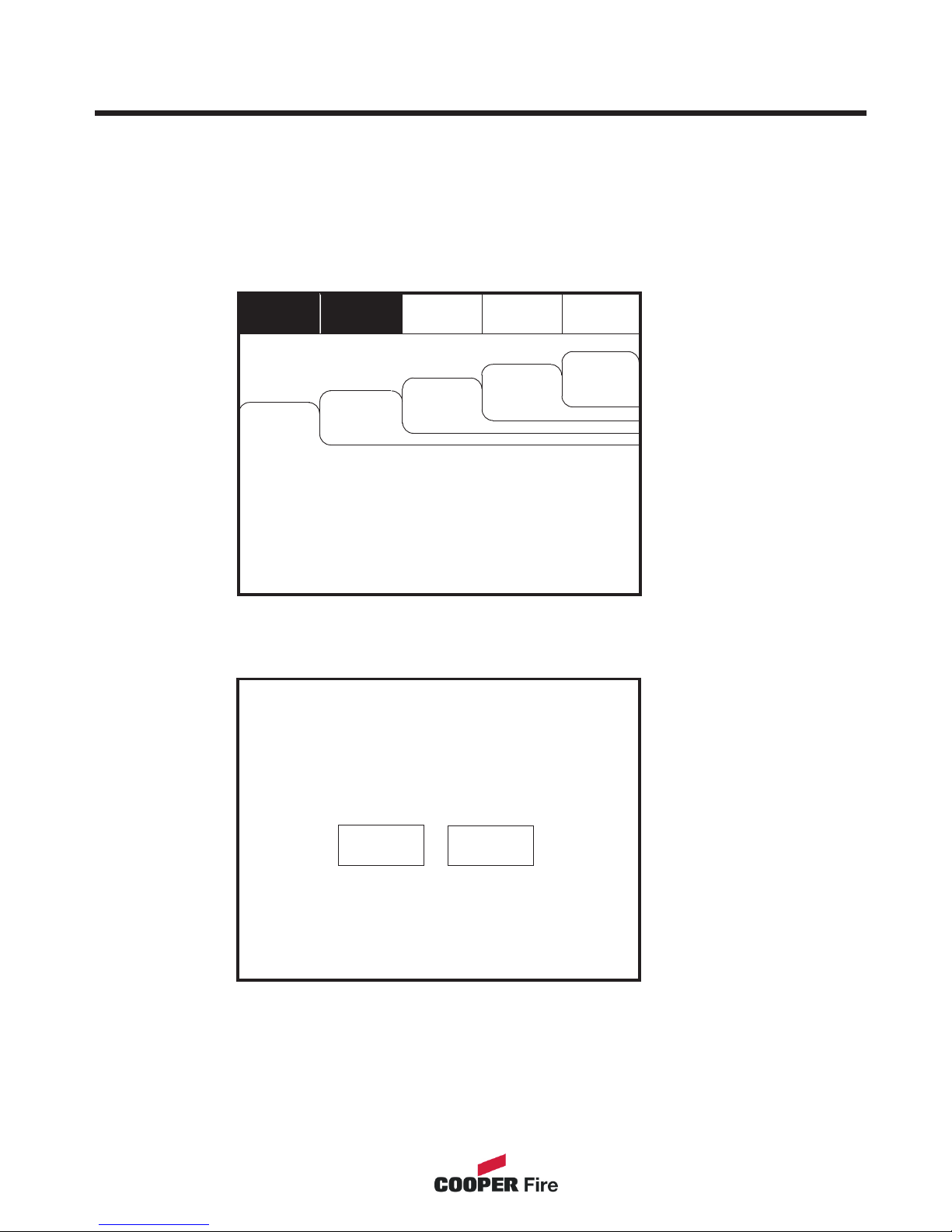
Enter the Supervisor Mode Passcode and select “Evacuate” on the menu at the top of
the screen.
Select “Yes” to evacuate the building.
Silence
Alarms
Reset
Supervisor
Others
View Fires
AC = 0
View Pre
Alarms
Disabled
Faults
Mute
Buzzer
Evacuate
This will activate ALL sounders
and activate all panel relays
Do you wish to continue?
Yes
No
To activate the touch screen, touch the top left corner of the screen until the screen
illuminates. To enter the supervisor mode touch the supervisor button and enter the
passcode.
23
Pre-alarm = Some smoke/heat but below fire threshold.
Disabled = Detectors, alarms etc that are switched off.
Faults = Short circuits, broken detectors etc.
Others = Enabled/Disabled, printing log, tests etc.
To silence all alarms, touch Silence Alarms
To activate all alarms, touch evacuate.
Page 24
Silence Alarms
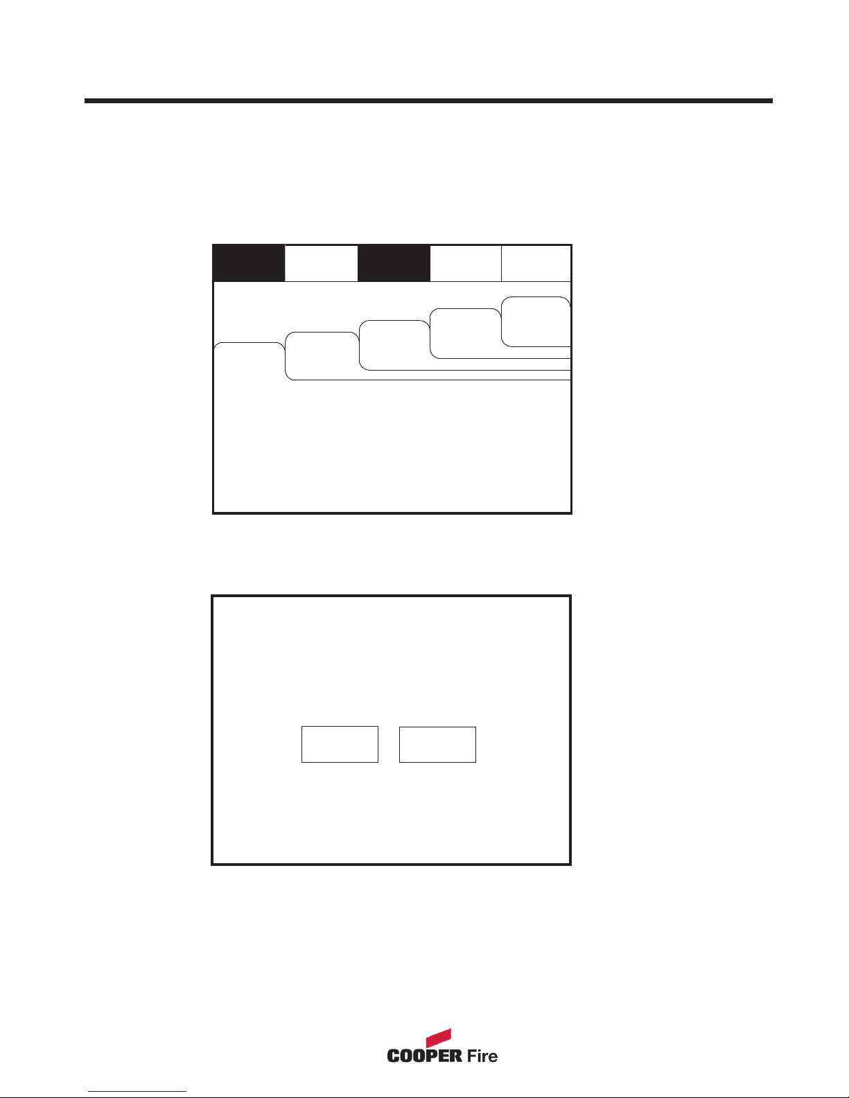
Enter the Supervisor Mode Passcode and select “Silence Alarms” button as the top of
the screen.
Select “yes” to silence Alarm.
This will silence ALL sounders
Do you wish to continue?
Yes
No
To activate the touch screen, touch the top left corner of the screen until the screen
illuminates. To enter the supervisor mode touch the supervisor button and enter the
passcode.
24
Silence
Alarms
Reset
Supervisor
Others
View Fires
AC = 0
View Pre
Alarms
Disabled
Faults
Mute
Buzzer
Evacuate
Pre-alarm = Some smoke/heat but below fire threshold.
Disabled = Detectors, alarms etc that are switched off.
Faults = Short circuits, broken detectors etc.
Others = Enabled/Disabled, printing log, tests etc.
To silence all alarms, touch Silence Alarms
To activate all alarms, touch evacuate.
Page 25
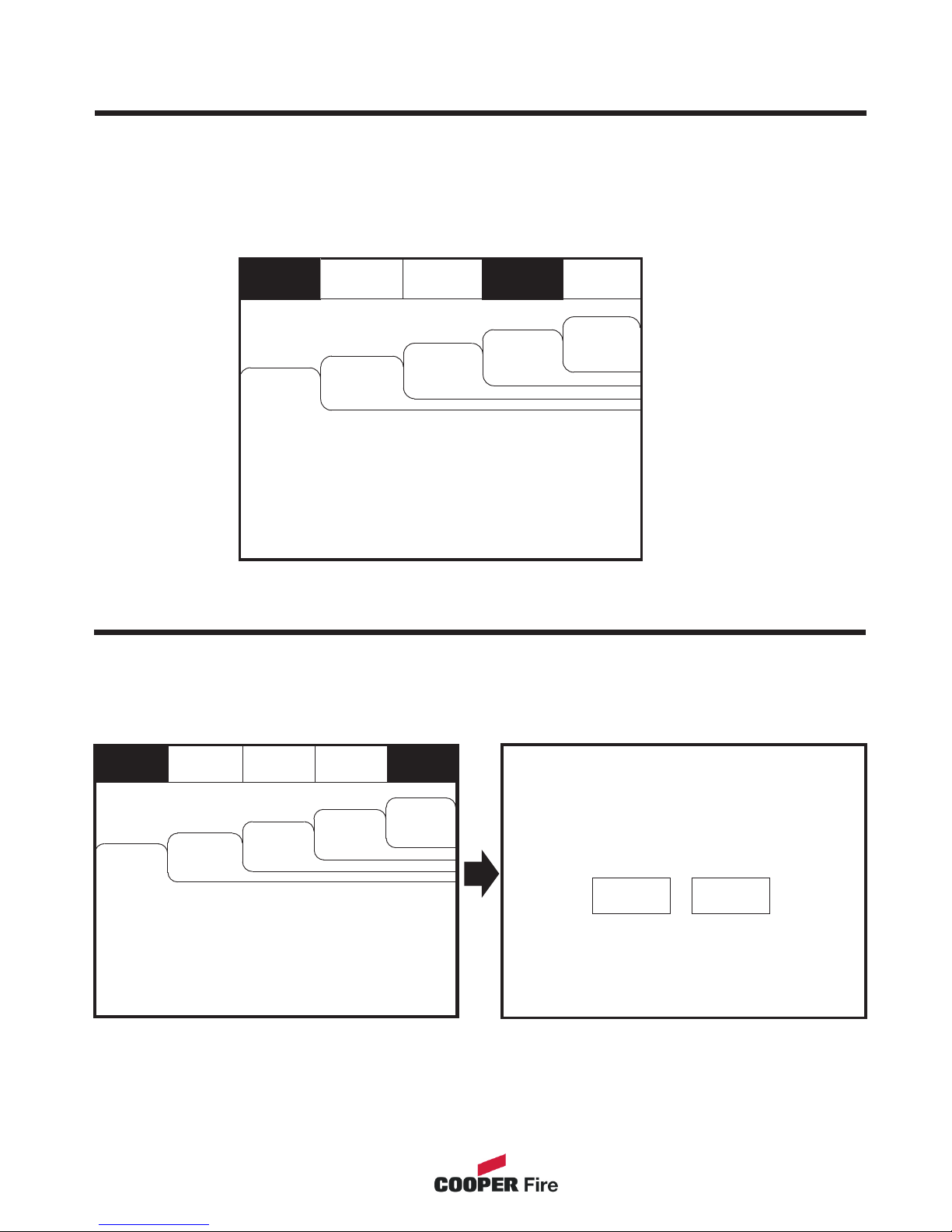
Evacuate
Silence
Alarms
Supervisor
Mute
Buzzer
Reset
Mute Buzzer
Enter the Supervisor Mode and Select “Mute Buzzer” from the Top Menu
Reset
Enter the Supervisor Mode and Select “Reset” from the top Menu. Select “Yes” to reset
the panel.
This will Reset the Panel
Do you want to continue?
Yes
No
To activate the touch screen, touch the top left corner of the screen until the screen
illuminates. To enter the supervisor mode touch the supervisor button and enter the
passcode.
25
Silence
Alarms
Reset
Supervisor
Others
View Fires
AC = 0
View Pre
Alarms
Disabled
Faults
Mute
Buzzer
Evacuate
Pre-alarm = Some smoke/heat but below fire threshold.
Disabled = Detectors, alarms etc that are switched off.
Faults = Short circuits, broken detectors etc.
Others = Enabled/Disabled, printing log, tests etc.
To silence all alarms, touch Silence Alarms
To activate all alarms, touch evacuate.
Others
View Fires
AC = 0
View Pre
Alarms
Disabled
Faults
Pre-alarm = Some smoke/heat but below fire threshold.
Disabled = Detectors, alarms etc that are switched off.
Faults = Short circuits, broken detectors etc.
Others = Enabled/Disabled, printing log, tests etc.
To silence all alarms, touch Silence Alarms
To activate all alarms, touch evacuate.
Page 26
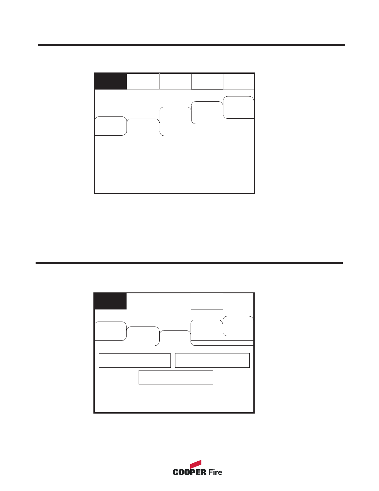
Enter the Supervisor Mode and Select “Pre-Alarms” tab.
A pre-alarm is shown when a detector appears to register heat or smoke but in a
quantity that is insufficient to warrant an alarm.
Pre-alarm may indicate a build up of dirt in a smoke detector which can be interpreted
by the detector as smoke presence.
Evacuate
Silence
Alarms
Reset
Supervisor
Others
View Fires
AC = 0
Pre-alarm = Some smoke /heat but below fire threshold
These warnings will appear and disappear
View Pre
Alarms
View
Disabled
View
Faults
Mute
Buzzer
Pre-Alarms
Enter the Supervisor mode and Select the “Disabled” tab.
Evacuate
Silence
Alarms
Reset
Supervisor
Mute
Buzzer
Others
View Fires
AC = 0
View Pre
Alarms
View
Disabled
View
Faults
Addresses: 0
Touch button to
View list
I/O
Zone: 0
The individual buttons show which devices and the number of devices which have been
disabled. Press one of the buttons to display detailed information for a particular
category
Disabled Devices
26
Page 27
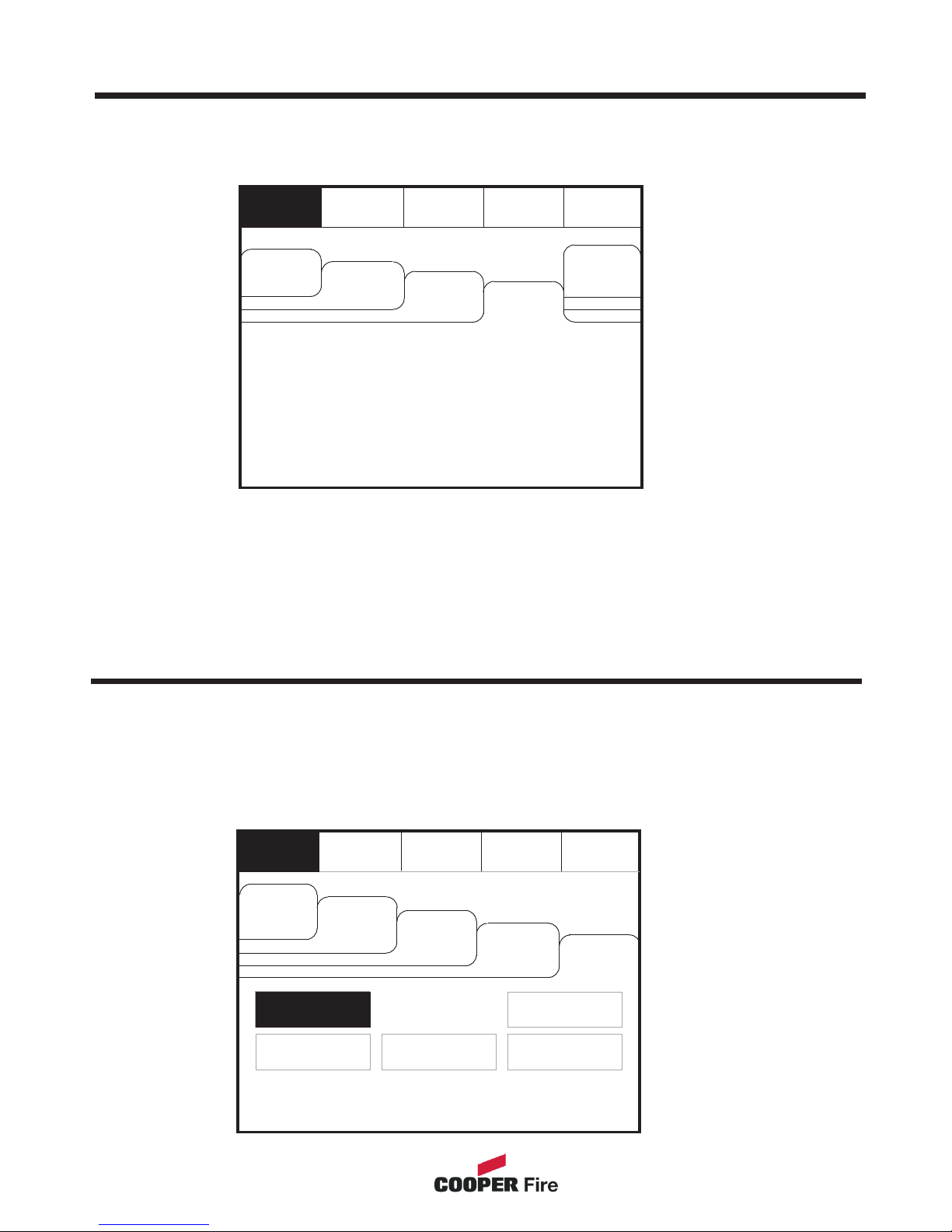
Faults
Enter Supervisor Mode Passcode and select “Faults” tab.
Evacuate
Silence
Alarms
Reset
Supervisor
Pre-alarm = Some smoke /heat but below fire threshold
These warnings will appear and disappear
Mute
Buzzer
Others
View Fires
AC = 0
View Pre
Alarms
View
Disabled
View
Faults
Enable/Disable (others Menu)
Evacuate
Silence
Alarms
Mute
Buzzer
Reset
Supervisor
Others
View Log
Print
View Fires
AC = 0
View Pre
Alarms
View
Disabled
View
Faults
Enable/Disable
Enter the Supervisor Mode passcode and select the “Others” tab.
To activate the touch screen, touch the top left corner of the screen until the screen
illuminates. To enter the supervisor mode touch the supervisor button and enter the
passcode.
27
Lamp test
Send Log to PC
Page 28
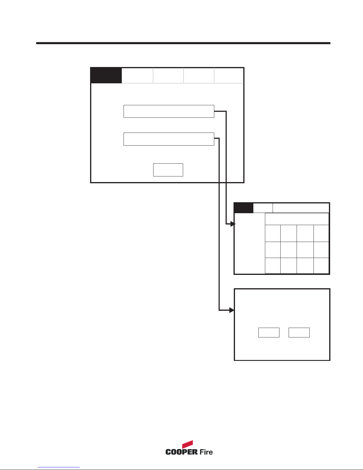
Evacuate
Silence
Alarms
Mute
Buzzer
Reset
Supervisor
Network Enable / Disable
Exit
Enable/Disable
Enable/Disable Address
Enable all Devices?
Do you want to continue?
Yes
No
The Enable/Disable
feature allows the
operator to disable part
or a whole system by
the sub menus shown
on the left.
28
Enable/Disable I/O
EXIT
NETWORK ENABLE / DISABLE
Supervisor
1
0
2
3
PANEL NUMBER
4
Del
Ok
5
6
7
8
9
Page 29
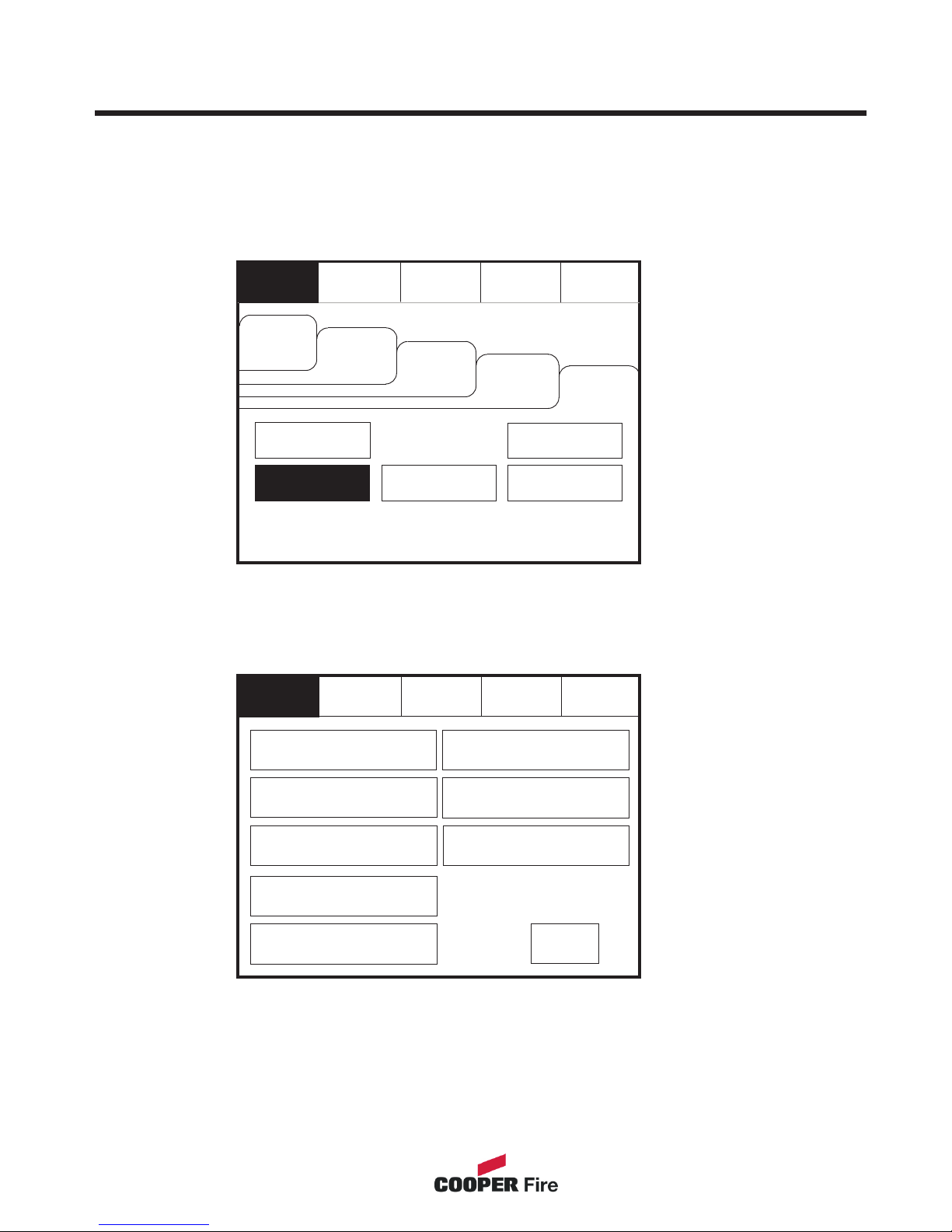
Print (function not availible)
Enter the Supervisor Mode and Select the “Others” Tab. Press “Print”
Select the Information You wish to Print from the Buttons Listed.
Evacuate
Silence
Alarms
Mute
Buzzer
Reset
Supervisor
Print Current Fires
Exit
Print Last 10 Log Records
Print Test Log
Print Disablements
Print Current Faults
Print All Log Records
Print Fire Log
To activate the touch screen, touch the top left corner of the screen until the screen
illuminates. To enter the supervisor mode touch the supervisor button and enter the
passcode.
Print Fault Log
29
Evacuate
Silence
Alarms
Mute
Buzzer
Reset
Supervisor
Others
View Log
Print
View Fires
AC = 0
View Pre
Alarms
View
Disabled
View
Faults
Enable/Disable
Lamp test
Send Log to PC
Page 30

Lamp Test
Enter the Supervisor Mode and Select the “Others” Tab. Press “Lamp Test”
Lamp Test
LED’s will light in
numerical order
Ok
Cancel
To activate the touch screen, touch the top left corner of the screen until the screen
illuminates. To enter the supervisor mode touch the supervisor button and enter the
passcode.
30
Evacuate
Silence
Alarms
Mute
Buzzer
Reset
Supervisor
Supervisor
Others
View Log
Print
View Fires
AC = 0
View Pre
Alarms
View
Disabled
View
Faults
Enable/Disable
Lamp test
Send Log to PC
Page 31
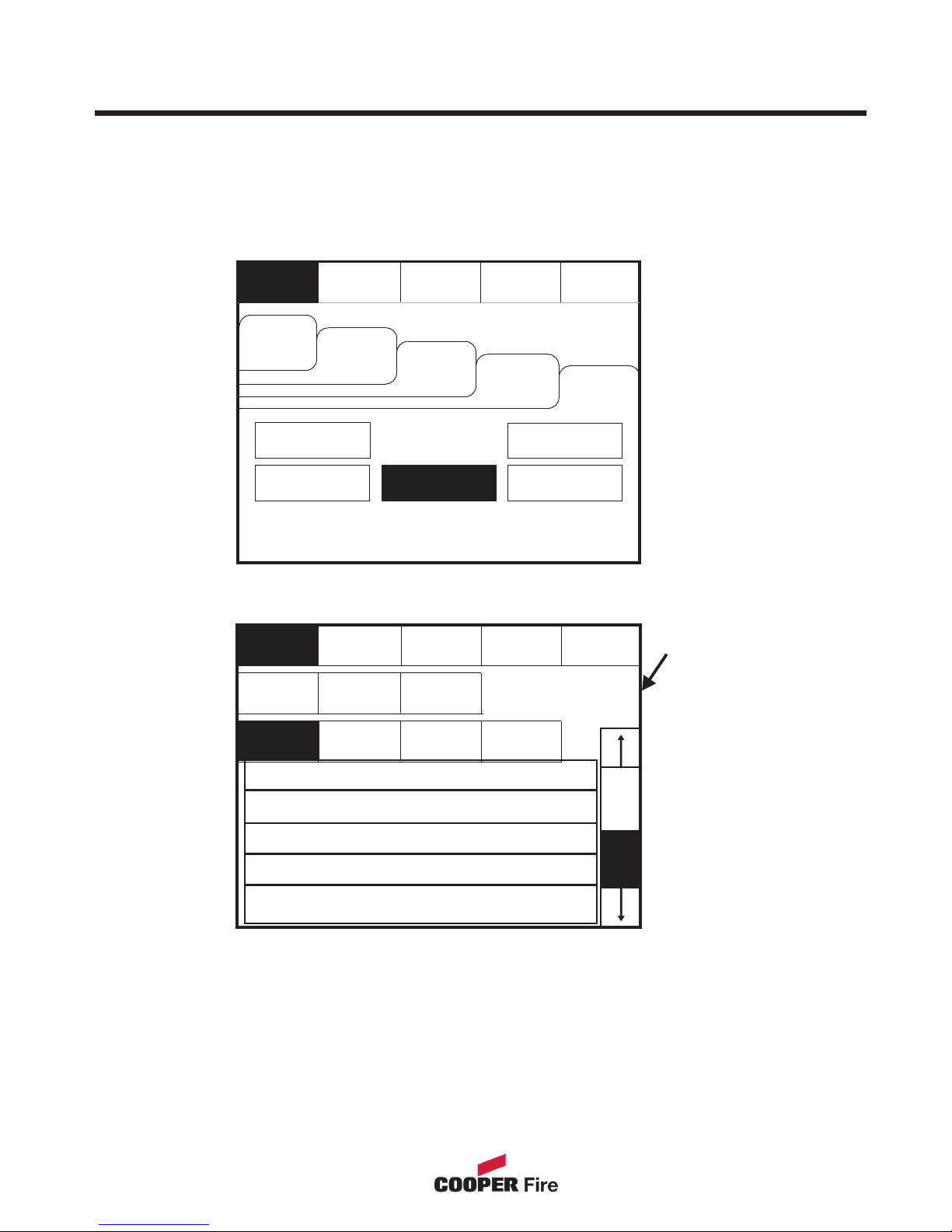
Viewing Events
Enter the Supervisor Mode Passcode. Select the “Others” tab and press View Log.
Evacuate
Oldest
Silence
Alarms
Show
Faults
Mute
Buzzer
Show
Fires
Show
Tests
Reset
Exit
Newest
Use the scroll bar to view the list of upto 1000 events.
The Panel event log stores up to 1000 events including, fires, faults, resets and address changes.
Once the maximum 1000 events has been reached Panel will automatically overwrite the oldest
event every time a new event is stored. The event log can only be reset by an approved service
engineer.
Events can be sorted
by selecting from the
sort option menu.
Supervisor
Show
All
To activate the touch screen, touch the top left corner of the screen until the screen
illuminates. To enter the supervisor mode touch the supervisor button and enter the
passcode.
002 FIRE! Lobby, [Optical] (Ana=150)
Building 1, Ground floor, Panel 1, Loop 1, device 1
001 Monday 13-Jan-2004 08:34:12
Hard Reset
003 Monday 06-Nov- 2000 11:22.56
Soft Reset
004 Monday 13-Nov-2001, 18:09.07 Fault
Panel1, Loop 2 Zone 2, Address 5
005 Monday 18-Feb-2001 22:20.18
Mains or Battery failure
31
Evacuate
Silence
Alarms
Mute
Buzzer
Reset
Supervisor
Others
View Log
Print
View Fires
AC = 0
View Pre
Alarms
View
Disabled
View
Faults
Enable/Disable
Lamp test
Send Log to PC
Page 32
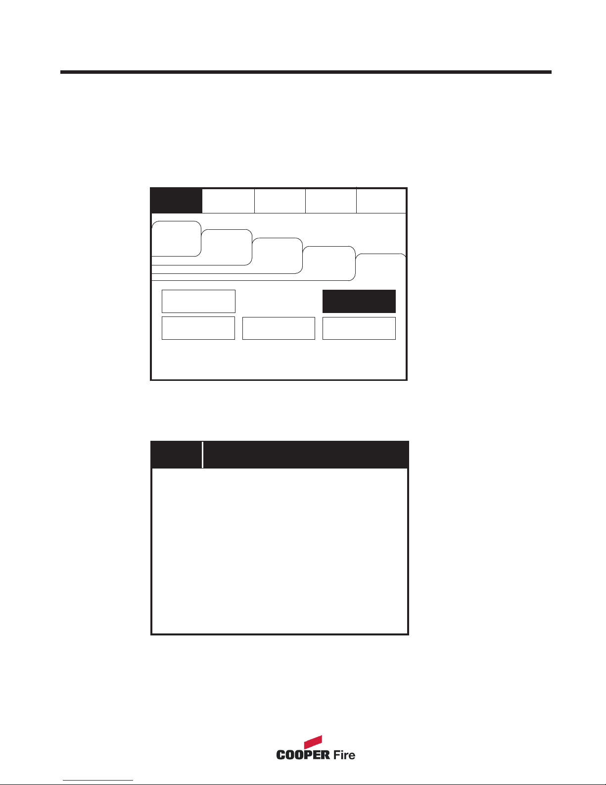
Send Log to PC
Enter the Supervisor Mode and Select the “Others” Tab. Press Send Log to PC.
XXXXXXXXXXXXXXXXXXXXXXXXXXXXXXXXXXXXXX
To activate the touch screen, touch the top left corner of the screen until the screen
illuminates. To enter the supervisor mode touch the supervisor button and enter the
passcode.
32
Waiting for PC...
Evacuate
Silence
Alarms
Mute
Buzzer
Reset
Supervisor
Cancel
Others
View Log
Print
View Fires
AC = 0
View Pre
Alarms
View
Disabled
View
Faults
Enable/Disable
Lamp test
Send Log to PC
Send Log to PC
Page 33
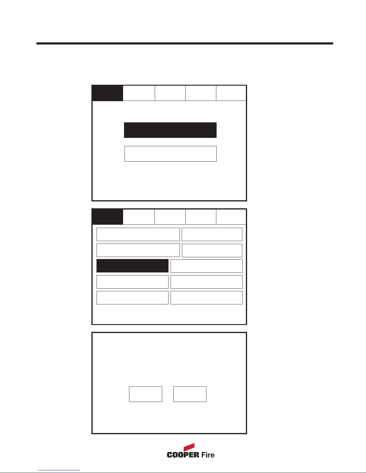
Erase Log
Enter the Service Mode and Select Commission.
This will delete all log entries
Do you want to continue
Yes
No
Select “Erase Log
and Reset” from the
Configure Menu
Screen.
To activate the touch screen, touch the top left corner of the screen until the screen
illuminates. To enter the supervisor mode touch the supervisor button and enter the
service passcode.
Service
Commission
Configure
Mute
Buzzer
Reset
33
Exit
Reset
Service
Load logo from PC
Load CDR from Laptop
Download CDR to Laptop
Erase Log
Repeater Mode
Printer Settings
Change Panel Number
Number of Panels
in Network
Mute
Buzzer
System Detail
Screen Cover
Page 34

System Details
Enter the Service Mode and Select Commission, then Press “System Details”.
To activate the touch screen, touch the top left corner of the screen until the screen
illuminates. To enter the supervisor mode touch the supervisor button and enter the
service passcode.
34
Service
FRE off
Reset
Program V0.00.15
Program Data 09-Mar-2004
Program Checksum 0xAA95524
CDR V0.5
CDR Checksum 0xF7D95E
Loop Controller 1 V0.0.0
Loop Controller 2 V0.0.0
Panel Number 0
Total Panels 1
Total Zones 4
Exit
Print
Service
Commission
Configure
Mute
Buzzer
Reset
Exit
Reset
Service
Load logo from PC
Load CDR from Laptop
Download CDR to Laptop
Erase Log
Repeater Mode
Printer Settings
Change Panel Number
Number of Panels
in Network
Mute
Buzzer
System Detail
Screen Cover
Page 35

Load Logo from PC
Enter the Service Mode and Select Commission.
Exit
Select “Load logo
from PC” from the
Configure Menu
Screen.
To activate the touch screen, touch the top left corner of the screen until the screen
illuminates. To enter the supervisor mode touch the supervisor button and enter the
service passcode.
Load logo from PC
35
Service
Commission
Configure
Mute
Buzzer
Reset
Exit
Reset
Service
Load logo from PC
Load CDR from Laptop
Download CDR to Laptop
Erase Log
Repeater Mode
Printer Settings
Change Panel Number
Number of Panels
in Network
Mute
Buzzer
System Detail
Screen Cover
Page 36
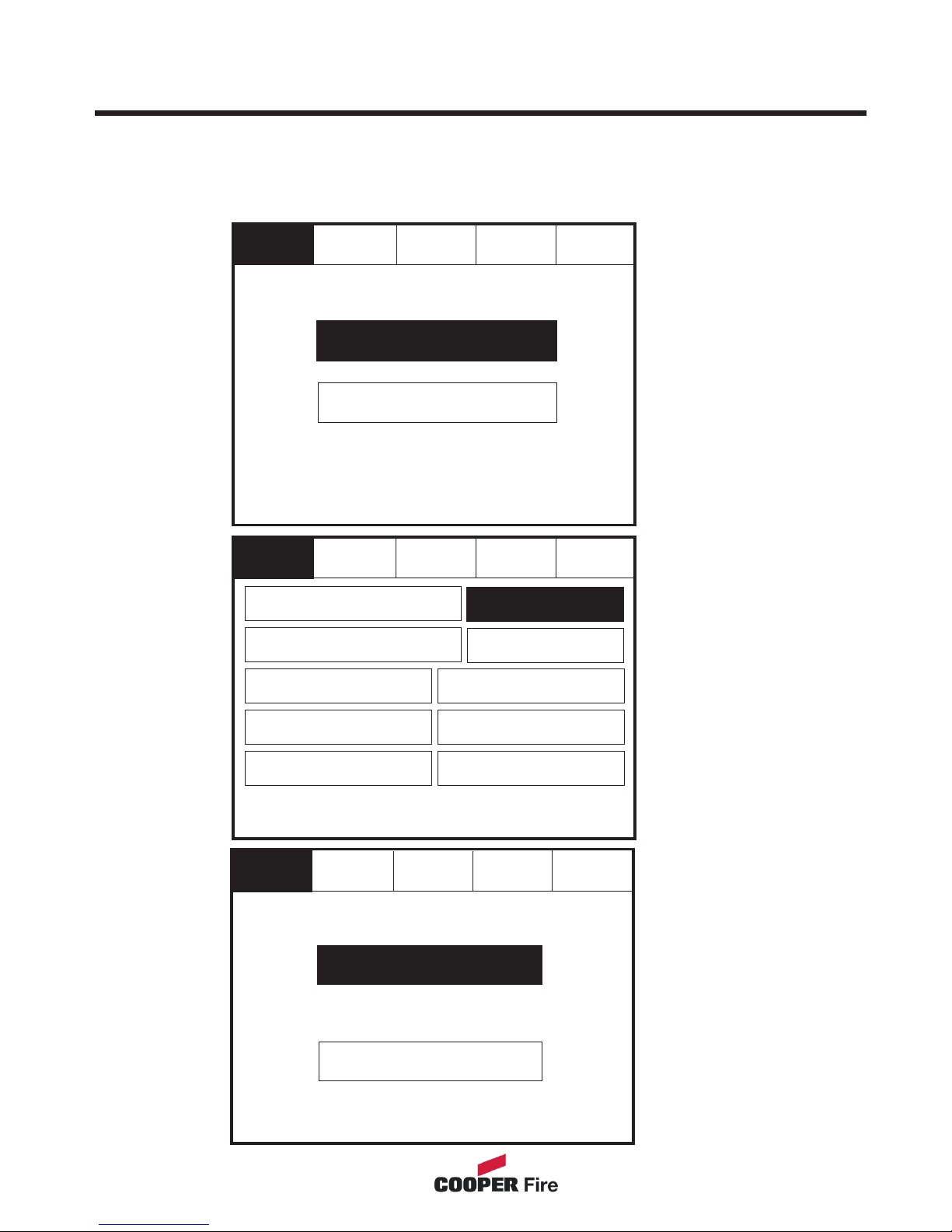
Repeater Mode
Enter the Service Mode and Select Commission.
The Repeater can be set as active or passive. Unlike the active repeater, the passive
repeater will only display information, no action from the repeater is transfered to the
network.
36
Service
Exit
Reset
Passive
Active
Service
Commission
Configure
Mute
Buzzer
Reset
Exit
Reset
Service
Load logo from PC
Load CDR from Laptop
Download CDR to Laptop
Erase Log
Repeater Mode
Printer Settings
Change Panel Number
Number of Panels
in Network
Mute
Buzzer
System Detail
Screen Cover
Press “Repeater
Mode”
Select “Active” for
an active repeater or
“Passive” for a
passive repeater
Page 37
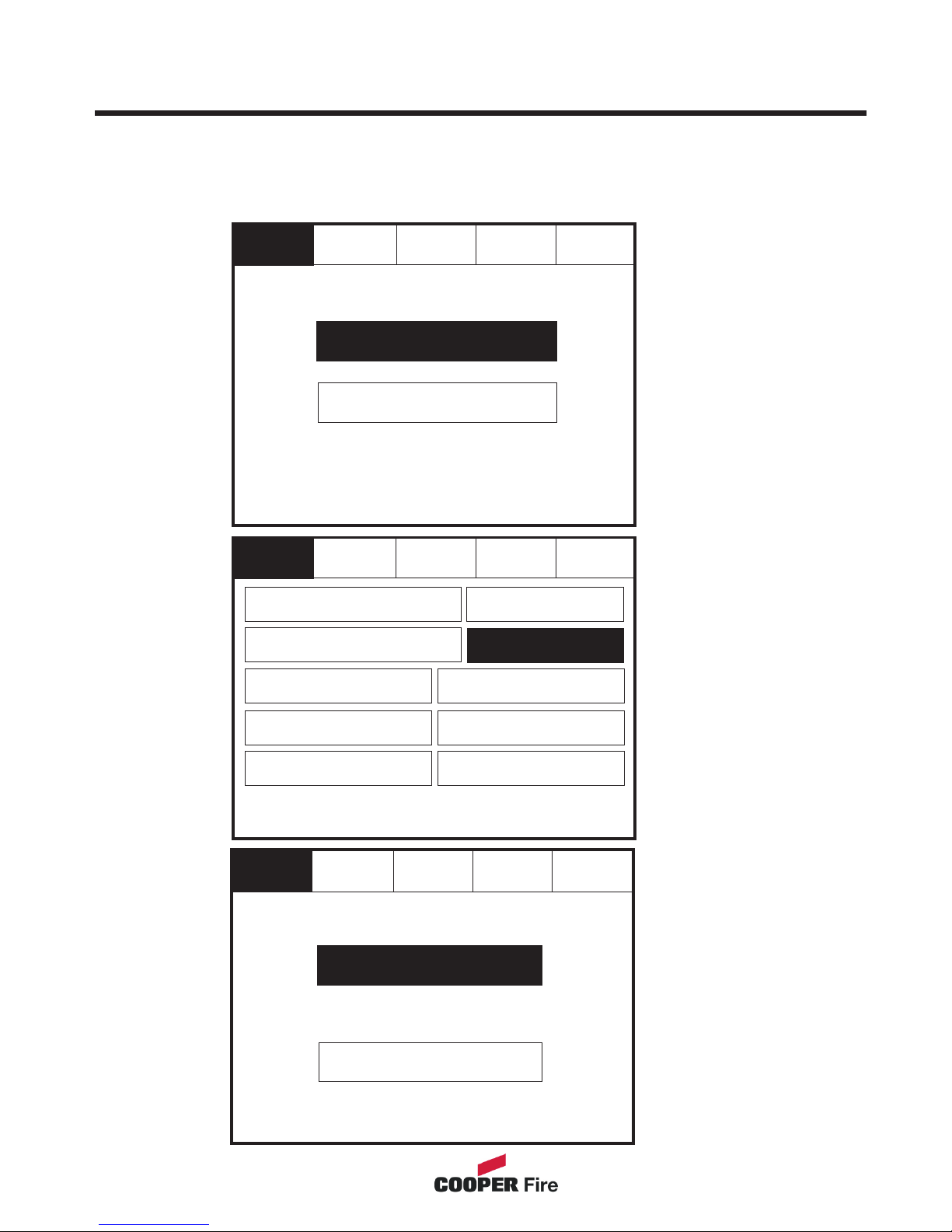
Printer Settings
Service
Exit
Reset
Request
Auto
To activate the touch screen, touch the top left corner of the screen until the screen
illuminates. To enter the supervisor mode touch the supervisor button and enter the
service passcode.
Enter the Service Mode and Select Commission then press “Printer settings”.
37
Service
Commission
Configure
Mute
Buzzer
Reset
Exit
Reset
Service
Load logo from PC
Load CDR from Laptop
Download CDR to Laptop
Erase Log
Repeater Mode
Printer Settings
Change Panel Number
Number of Panels
in Network
Mute
Buzzer
System Detail
Screen Cover
Page 38
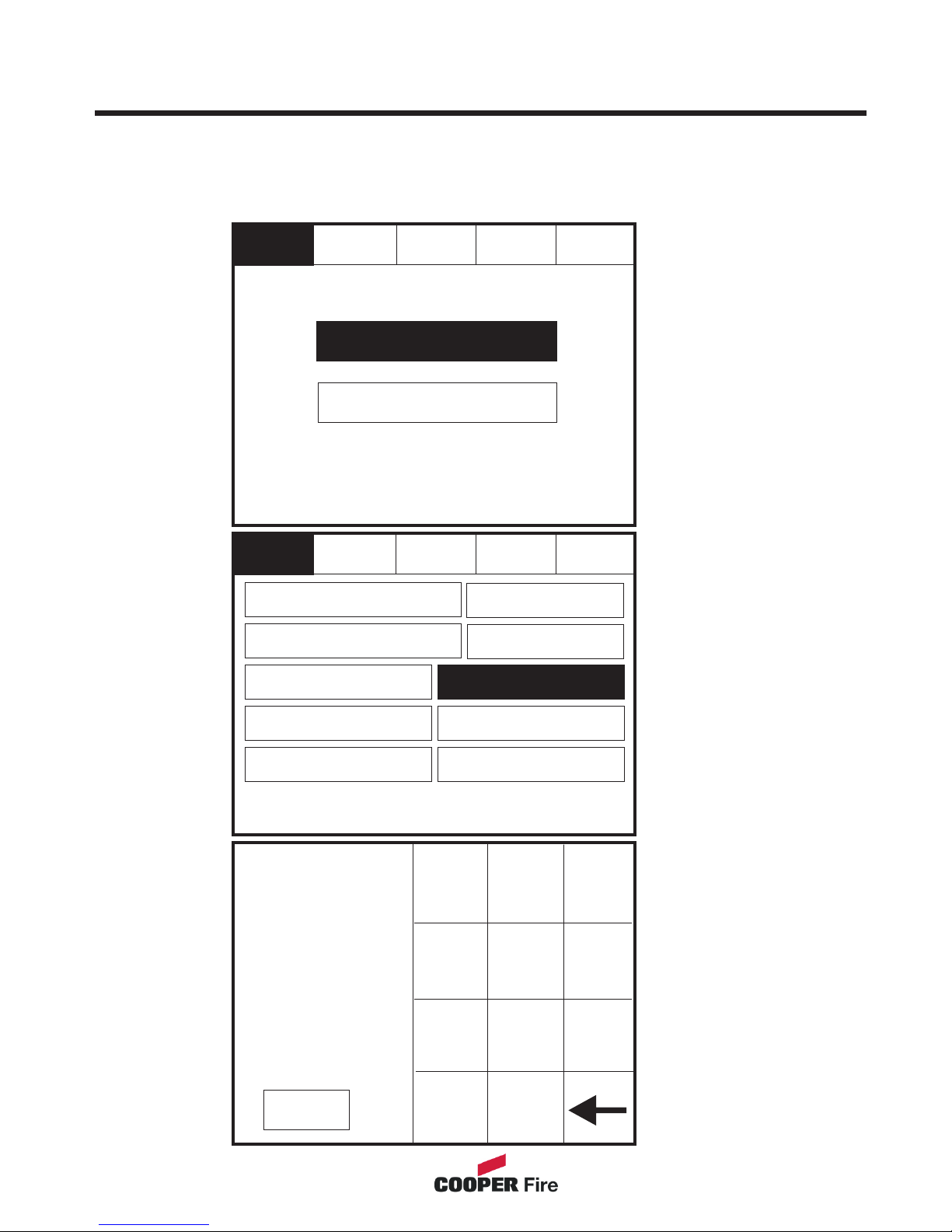
Change Panel Number
Change Panel Number
0
1
4
5
6
7
8
9
ok
0
2
3
..............................
Cancel
To activate the touch screen, touch the top left corner of the screen until the screen
illuminates. To enter the supervisor mode touch the supervisor button and enter the
service passcode.
Enter the Service Mode and Select Commission then press “Change Panel Number”
38
Service
Commission
Configure
Mute
Buzzer
Reset
Exit
Reset
Service
Load logo from PC
Load CDR from Laptop
Download CDR to Laptop
Erase Log
Repeater Mode
Printer Settings
Change Panel Number
Number of Panels
in Network
Mute
Buzzer
System Detail
Screen Cover
Page 39
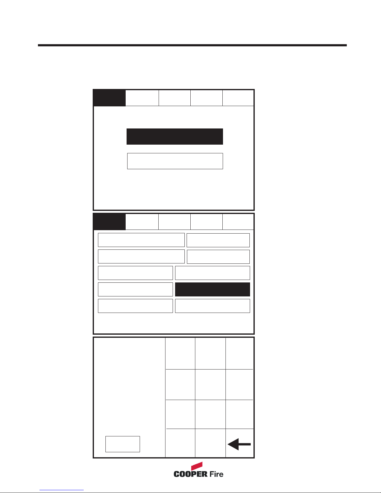
Number of Panels in Network
To activate the touch screen, touch the top left corner of the screen until the screen
illuminates. To enter the supervisor mode touch the supervisor button and enter the
service passcode.
Enter the Service Mode and Select Commission then press “Number of Panels in
39
Change Panel Number
0
1
4
5
6
7
8
9
ok
0
2
3
..............................
Cancel
Service
Commission
Configure
Mute
Buzzer
Reset
Exit
Reset
Service
Load logo from PC
Load CDR from Laptop
Download CDR to Laptop
Erase Log
Repeater Mode
Printer Settings
Change Panel Number
Number of Panels
in Network
Mute
Buzzer
System Detail
Screen Cover
Page 40
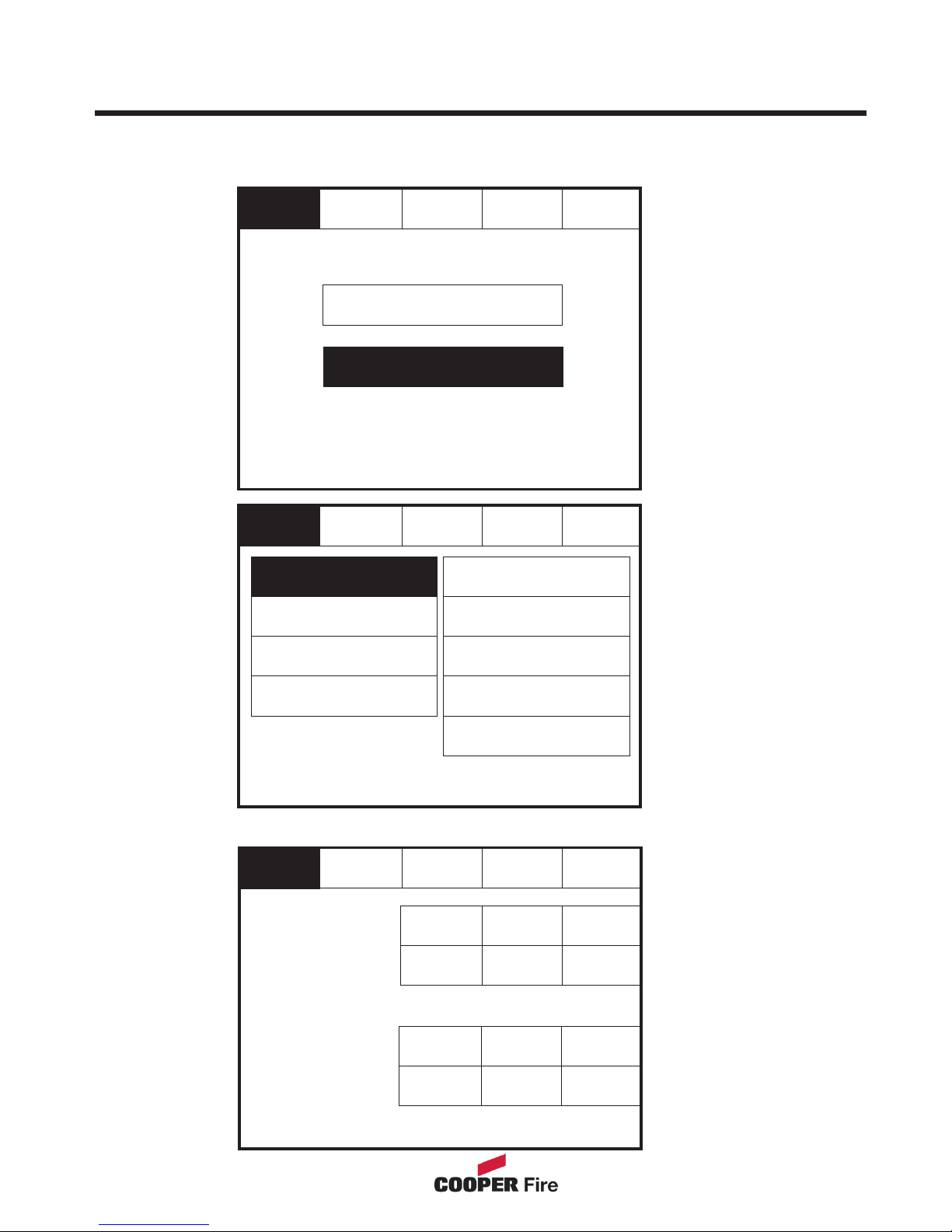
Change Date/Time
Service
Reset
Change Password
Relay Control
Programmable Input
Exit
Mute
Buzzer
Change Date/Time
Add/Delete Zone
Language
Network
Network Protocol
Power Supply
Service
Reset
Ok
Cancel
Current Time:
Current Date:
Wednesday
dd-mmm-yyyy
BST On
+1
Hour
+1
Day
-1
Hour
-1
Day
-10
Mins
-1
Month
-1
Mins
-1
Year
+10
Mins
+1
Month
+1
Mins
+1
Year
10:16:12
Enter the Service Mode and Select Configure. Select Change Date/Time.
Set the Time Using the Buttons Shown Below.
40
Service
Commission
Configure
Mute
Buzzer
Reset
Page 41
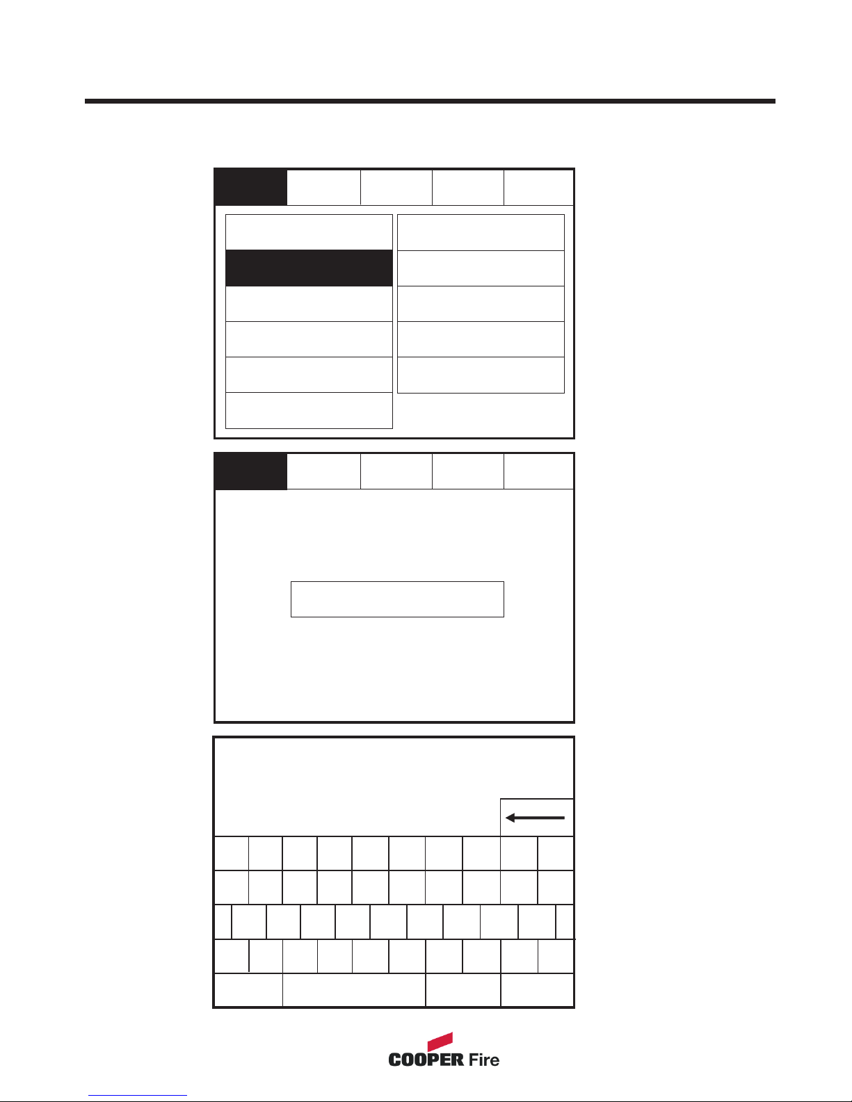
Change Panel Text
Enter the Service Mode and Select Configure. Select “Change Text”
Press “Change
Panel Text”
1
Q
A
Z
X C V B
S D F G
CAPS
OTHER
.......................................................................................
CF1100
Correct Panel Text
SPACE
W E R
T
Y
2
3 4 5 6
U
I
O P
7 8 9 0
N M
,
.
H J K L
OK CANCEL
41
Service
Reset
Exit
Change Panel Text
Change zone text
Change zone text
Mute
Buzzer
Service
Reset
Change Password
Relay Control
Programmable Input
Exit
Mute
Buzzer
Change Text
Change Date/Time
Configure Zones
Add/Delete Zone
Language
Network
Network Protocol
Power Supply
Page 42

Change Passcode
Please enter Passcode:
New Code:
Verify New Code:
1
4
5
6
7
8
9
ok
0
2
3
..............................
..............................
..............................
Passcode is not correct.
No change made
Ok
Verification is incorrect
No change made
New Password accepted
Saved
Ok
Ok
Enter the Service Mode and Select Configure. Select “Change User Code”
Cancel
42
Service
Reset
Change Password
Relay Control
Programmable Input
Exit
Mute
Buzzer
Change Text
Change Date/Time
Configure Zones
Add/Delete Zone
Language
Network
Network Protocol
Power Supply
Page 43
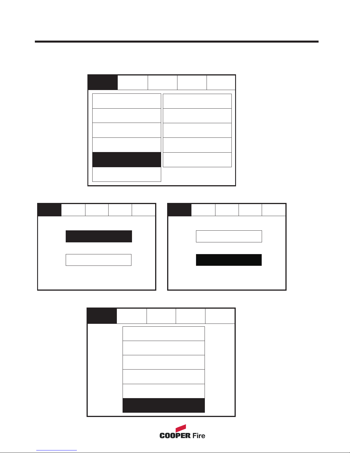
Relay Control
The repeater is equipped with 2 programable relays configured as volt free contact.
Enter the Service Mode and Select Configure. Select “Relay Control”
Select the type of relay either “Aux Relay” or “Fault Relay”
Select the desired mode
43
Service
Reset
Change Password
Relay Control
Programmable Input
Exit
Mute
Buzzer
Mute
Buzzer
Mute
Buzzer
Change Text
Change Date/Time
Configure Zones
Add/Delete Zone
Language
Network
Network Protocol
Power Supply
Service Service
Exit Exit
Reset Reset
Fault Relay Fault Relay
Aux Relay Aux Relay
Mute
Buzzer
Service
Exit
Reset
On Disablement
On Fault
On Test
On Pre-Alarm
On Fire
Not Required
Page 44
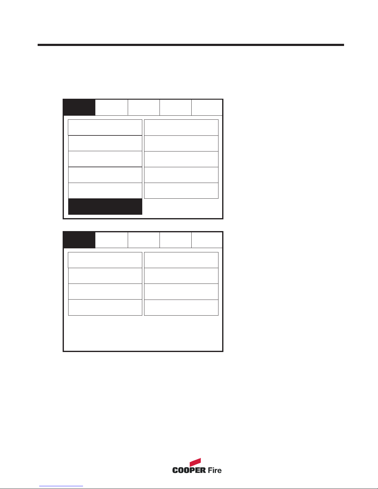
Programmable Input
The Repeater is equipped with a programable input which can operate across the
network if the repeater is programmed as active.
Enter the Service Mode and Select Configure. Select “Programmable Input”
44
Service
Service
Reset
Reset
Change Password
Not Required
Relay Control
Programmable Input
Exit
Exit
Mute
Buzzer
Mute
Buzzer
Change Text
Evacuate
Change Date/Time
Reset
Configure Zones
Silence
Add/Delete Zone
Fire
Language
Fault
Network
Pre-Alarm
Network Protocol
Prog Input Text
Power Supply
Select Zone into which
device will be added
Select the mode of
operation from the menu
Page 45
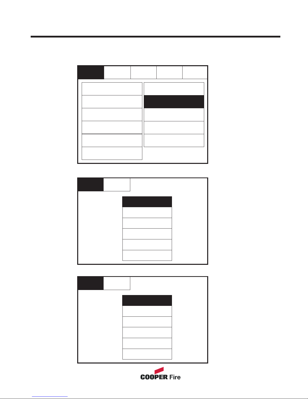
Network
Select the specific required . E.g “Reset”
Enter the Service Mode and Select Configure. Select “Network”, This menu defines
whether messages are broadcast across the network or remain local.
Network
Not Required
Network
Network
Network
Network
Network
Network
Reset
Reset
Receive message over network
Receive message over network
Evacuate
Evacuate
Silence
Silence
Fire
Fire
Network
Network
Network
Network
Pre-Alarm
Pre-Alarm
Fault
Fault
Select if Network is required to be on/off
45
Service
Service
Service
Reset
Change Password
Relay Control
Programmable Input
Exit
Exit
Exit
Mute
Buzzer
Change Text
Change Date/Time
Configure Zones
Add/Delete Zone
Language
Network
Network Protocol
Power Supply
Page 46
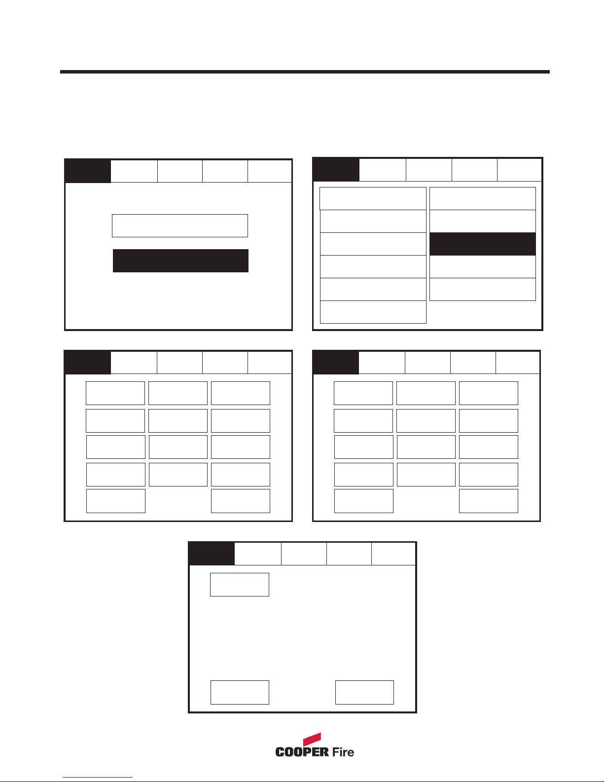
Language
Enter the Service Mode and Select Configure.
Service Service
Service
Reset Reset
Reset
Exit Exit
Exit
To activate the touch screen, touch the top left corner of the screen until the screen
illuminates. To enter the supervisor mode touch the supervisor button and enter the
service passcode.
Mute
Buzzer
Mute
Buzzer
Mute
Buzzer
Page 3 Page 3
Page 3
Magyar Suomi
Cesky Viêt
Slovensky Afrikaans
Chinese Greek
Dansk Eeesti
Nederlands(BE) Russian
Português Svenska
Deutsch Latviesu
Italiano Espanol
Français Polski
Nederlands Hrvatski
English Slovenski
Türkçe
46
Service
Reset
Change Password
Relay Control
Programmable Input
Exit
Mute
Buzzer
Change Text
Change Date/Time
Configure Zones
Add/Delete Zone
Language
Network
Network Protocol
Power Supply
Page 2 Page 1
Page 2
Service
Commission
Configure
Mute
Buzzer
Reset
Select “Language”
from the Configure
Menu Screen.
Then press select
required language
from the 3 available
pages.
Page 47
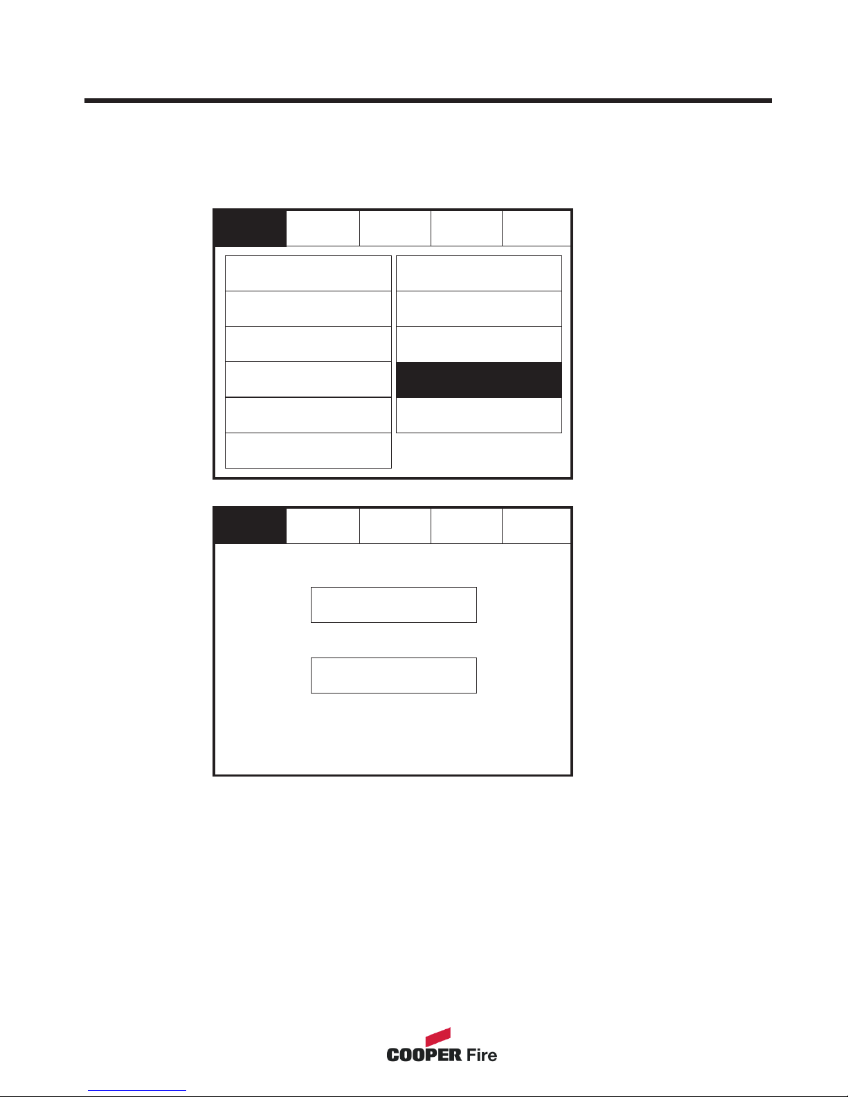
Network Protocol
Enter the Service Mode and Select Configure.
To activate the touch screen, touch the top left corner of the screen until the screen
illuminates. To enter the supervisor mode touch the supervisor button and enter the
service passcode.
47
Service
Reset
Change Password
Relay Control
Programmable Input
Exit
Mute
Buzzer
Change Text
Change Date/Time
Configure Zones
Add/Delete Zone
Language
Network
Network Protocol
Power Supply
Service
Reset
Exit
Network Protocol V1
Network Protocol V2
Page 48
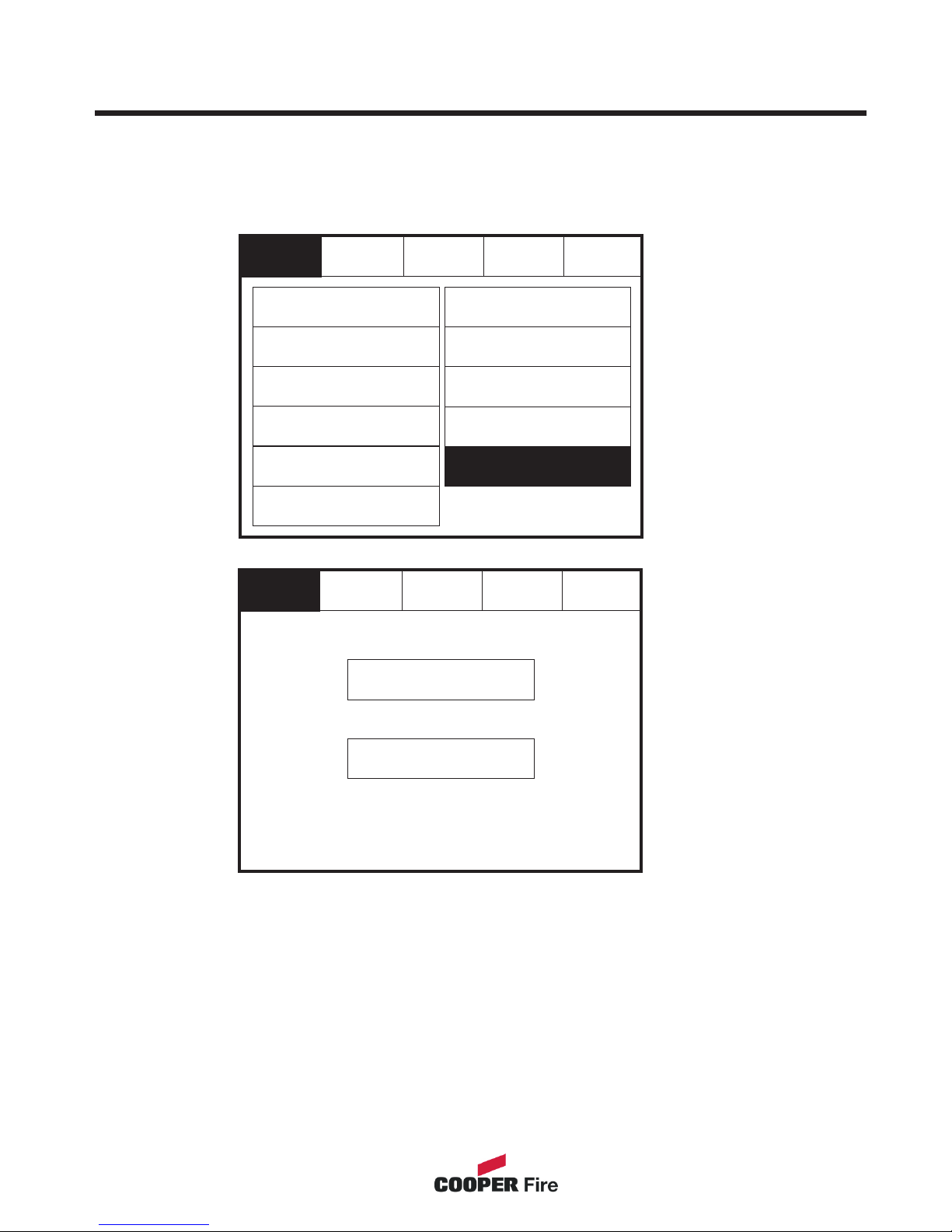
Power Supply
Enter the Service Mode and Select Configure.
To activate the touch screen, touch the top left corner of the screen until the screen
illuminates. To enter the supervisor mode touch the supervisor button and enter the
service passcode.
48
Service
Service
Reset
Reset
Change Password
Relay Control
Programmable Input
Exit
Exit
Mute
Buzzer
Change Text
Change Date/Time
Internal Power
External Power
Configure Zones
Add/Delete Zone
Language
Network
Network Protocol
Power Supply
Page 49
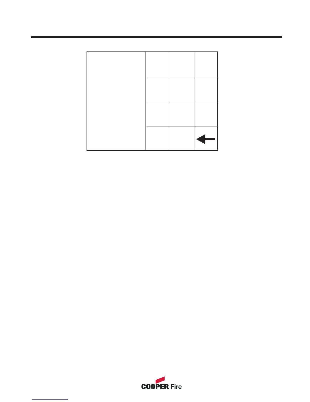
Password Protection
The system has password protection which restricts access to the DISABLE Menu and
to TEST/COMMISSIONING MODE. The password is a four digit code and the default
number is 2214. The password entry screen is accessed via the supervisor mode
button. Press supervisor mode and the password entry screen will be displayed, type in
the passcode and press Ok. If the wrong password is entered three times further
access to the system is denied.
Please enter Passcode
1
4
5
6
7
8
9
ok
0
2
3
49
Page 50

Appendix
Section 4
50
Page 51
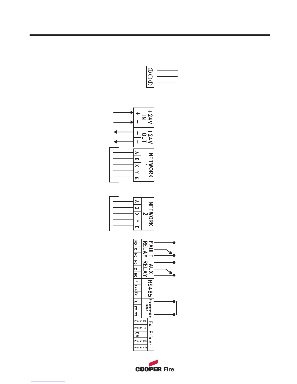
System Wiring
51
L
E
N
MAINS
Use Network 1 for
standard network
Use both Network 1 & 2
for Dual Network
Switch / contactor, timer etc.
(apply no voltage)
Network
card 1
Network
card 2
 Loading...