

Cooper Controls Greengate CK4-120NO, Greengate CK4-277N, Greengate ControlKeeper 4 Installation Sheet
Page 1
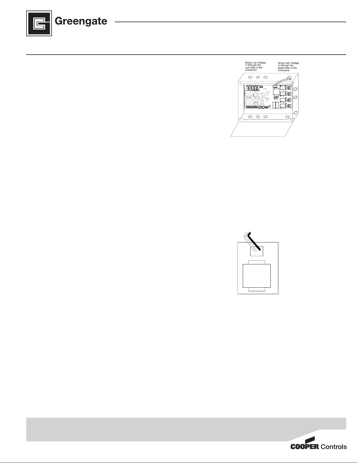
ControlKeeper® 4
Line = 120V (Black),
277V (Orange)
Neutral = White
277V Transformer
Line = Orange
Neutral = White
120V Transformer
Line = Black
Neutral = White
General Information
The ControlKeeper-4 model is shipped in one package and
is congured with either a 120V or a 277V transformer. It is
factory congured with Normally Open relays. Please refer
to your order information to determine which model you have
purchased.
Getting Started
1. Do not discard these installation instructions. Please keep
for future reference and operation information.
2. Always disconnect all power before wiring.
3. Use only as intended and at the listed voltage.
4. All installation and service must be performed by qualied
personnel or service technicians.
5. Install in accordance with the National Electrical Code and
any other codes which may apply.
6. Installation and wiring information contained in this document is based on industry-accepted standards and practices. If conicts exist between these instructions and any
applicable codes or ordinances, please contact Greengate
before proceeding with the installation.
7. High Voltage is present inside the enclosure. Use extreme
caution when performing maintenance on this equipment.
Failure to follow this warning and proper safety procedures
could result in severe injury or death, and/or damage to
the equipment.
8. Document all wiring and device terminations and locations so that devices can be properly congured and
programmed for operation.
Mounting the Cabinet
1. Choose a dry location on a rm surface convenient to the
circuits being controlled. Allow full clearance for the door
of the enclosure to open fully.
2. Mount the ControlKeeper-4 cabinet using the holes provided in the back of the enclosure. It is recommended that
the panel be mounted vertically.
3. All Line Voltage conductors must enter the cabinet on the
right side of the enclosure.
4. All Low Voltage conductors must enter the cabinet on the
left side of the enclosure.
5. Remove all debris and metal shavings from the enclosure
before applying power to the ControlKeeper-4.
INSTALLATION SHEET
Model# CK4-120NO-
Model# CK4-277NO
Figure-1 ControlKeeper-4 Enclosure
Power Supply Wiring
The ControlKeeper-4 is factory congured with either a 120V
or a 277V transformer. Transformer voltages are color coded.
It is recommended that a dedicated branch circuit with circuit
protection be used for power supply wiring.
1. Connect neutral wire to the white wire.
2. If the transformer is a 277V model, connect orange wire to
a 277V circuit. If the transformer is a 120V model, connect
black wire to a 120V circuit.
Figure-1 ControlKeeper-4 Enclosure
Connecting Relay Loads
1. Test branch circuits for short circuits prior to connecting and
energizing the ControlKeeper-4.
2. Relay terminal blocks have a maximum limit of 10 AWG wire.
3. Relays are rated for single-pole circuit use. Connection of 2
pole circuits/loads to the ControlKeeper-4 will void the
equipment warranty.
4. Connect a 120 or 277 volt, 20 amp maximum, de-en-
ergized branch circuit breaker to the relay terminal block
position labeled LINE.
Cooper Controls
203 Cooper Circle, Peachtree, GA 30269
800-553-3879
www.coopercontrol.com
Page 2
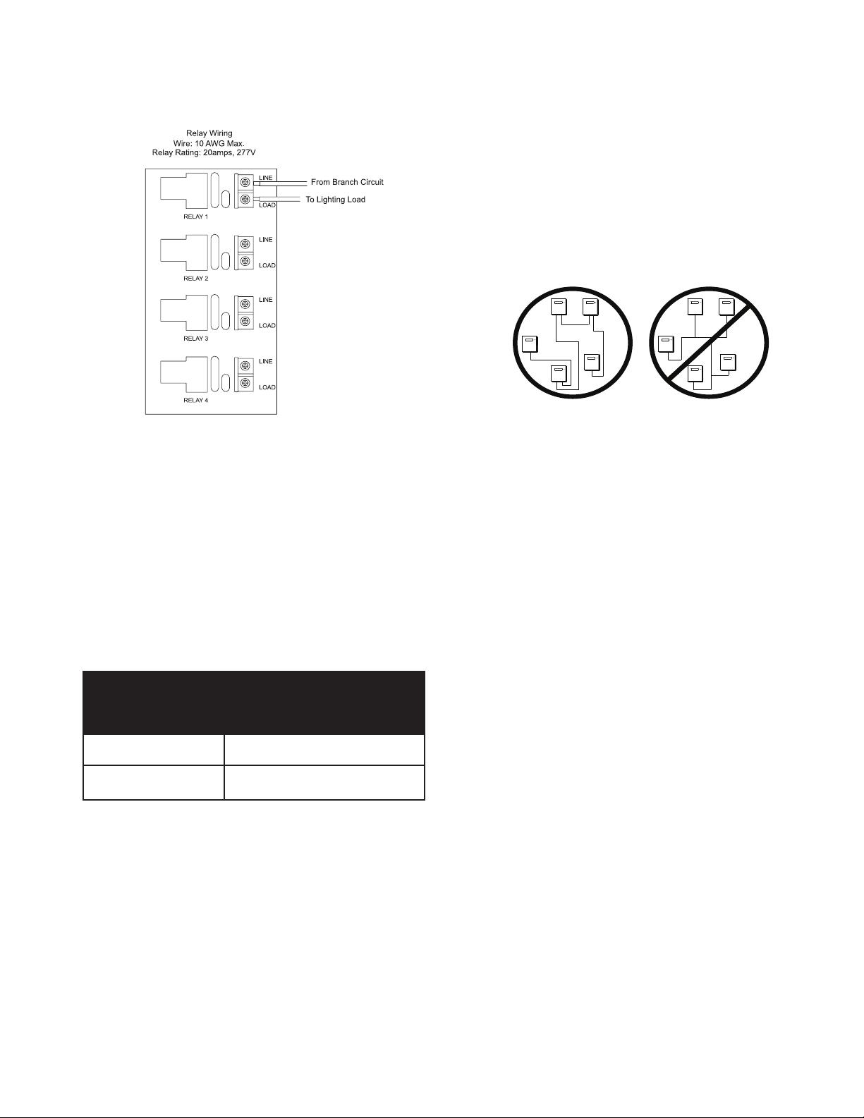
5. Connect the load to the output terminal block position la-
beled LOAD.
6. Tighten down relay terminal screws. Manufacturer’s recommended torque rating is 7lbs-in. (0.59 lbs-foot) (0.8Nm).
1. All low voltage wiring is Class 2.
2. All low voltage wiring must enter the cabinet from the left
side of the enclosure.
3. All low voltage wiring must be run in separate conduit from
line-voltage wiring.
4. Test all network wiring for shorts to AC ground before connecting to the ControlKeeper-4 panel.
5. If using Belden 9841 or 89841, leave all shields disconnected
making certain that shield is not exposed.
6. Panels and devices on the RS-485 lighting network should
be daisy chained. Do not create a Star or T-Tapped
conguration.
Figure-6 Address Switch Information
Note: Neutrals terminate within the adjoining lighting panel.
Network Wiring Notes
The ControlKeeper-4 is designed to communicate with other
ControlKeeper network panels using a lighting control RS-485
network for communications. This allows the panels to share
information and to be programmed from one central location
by a computer with the Keeper Enterprise Software.
Please refer to Table-1 for information on recommended wiring
for network.
Acceptable
Suggested Cable
Network Wiring
Standard RS485 Belden 9841
(shield is not used)
Plenum RS485 Belden 89841 (shield is not used)
Table-1 Network Wiring Recommendations
For best network performance, one of the suggested cables
should be used. If the specied cable is not used and
communications problems occur that require troubleshooting
assistance, additional charges for support may be assessed.
7. Total network length should not exceed 4000 feet.
Network Wiring Details
1. Before wiring, select the two panels that are going to be
the end panels of the network and plan a wiring scheme
accordingly. Panels should be daisy chained, not Star or
T-Tapped.
2. Starting at one of the end panels, connect the network +
and - terminals to the next panel’s network + and - terminals.
Continue this process through the network making certain
to observe polarity. When nished, the two end panels will
have a single pair of wires coming into the network terminal
block while all middle panels in the network will have two
sets of wires.
3. Set the network termination jumpers. On the end panels on
the network set to the terminated position. For all panels in
the middle of the network, remove the network termination
jumper. See Figures-4&5 for details.
4. On the two end panels in the network, set the network
termination jumpers to the terminated position.
5. On the middle panels in the network, remove the network
termination jumpers.
6. Set all panel addresses using the panel network identication DIP Switches on each panel. See Figures 5&6 for
location and details.
7. Using the panel reset switch, issue a soft reset to each panel
to initialize the panel address. See Figure-5 for location of
the reset switch.
Page 2
Page 3
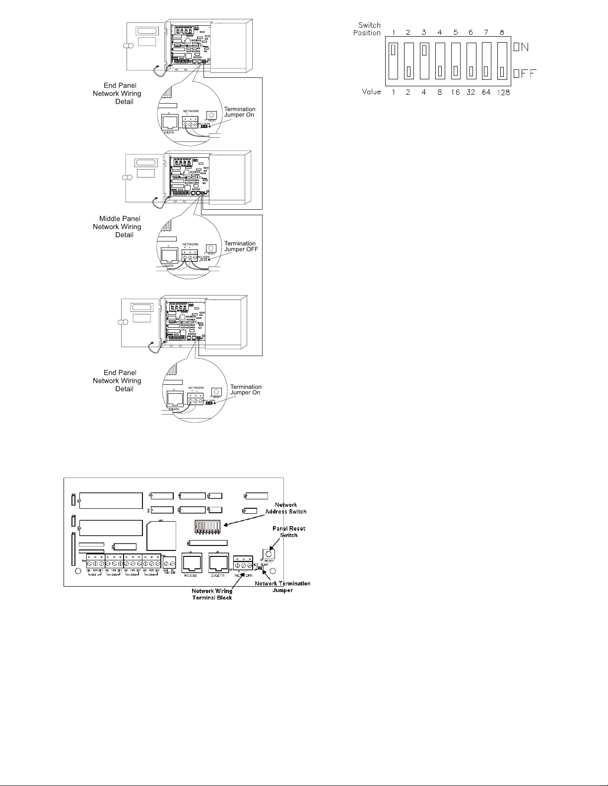
All panels must be assigned a unique Network Address in order to
communicate over the lighting network. Switch positions are
labeled 1 through 8 and are valued at 1 through 128 as shown above.
The network address is calculated by adding the value of the switch
positions that are in the ON position. In the example above,
switches 1 and 3 are ON giving the panel the network address of 5.
Addresses 1 through 254 are valid addresses. Zero and 255 are
reserved for system use. To initialize the network address with the
controller, press the panel reset button after the address is set.
TB1TB2TB3
TB4
LINE
LOAD
LINELOAD
To Lighting Load
To Circuit Breaker #1
To Circuit Breaker #2
To Lighting Load
Figure-4 Network Wiring Detail
Figure-5 Item Reference for Network Details
Page 3
Figure-6 Address Switch Information
Connecting Low Voltage Inputs
The ControlKeeper-4 logic board can support both dry contact
closure and Digital Switch inputs. If a combination of contact
input switches and Digital Switches are being used, the combined total cannot exceed 64 inputs.
Regardless of input type used, it is recommended that all input
wiring be done prior to applying power to the logic board or at
the very least with the terminal blocks removed from the logic
board. Please verify that there are no shorts to AC Ground
prior to connection of input devices. Regardless of input type,
the following notes apply.
1. All low voltage wiring is Class 2 wiring.
2. All low voltage wiring must enter the cabinet into the Low
Voltage section of the enclosure. Low Voltage wiring can be
brought into the enclosure from the left side of the enclosure.
Failure to separate high voltage from low voltage wiring
may cause interference with logic board function.
3. All low voltage wiring must be run in separate conduit from
line voltage wiring.
4. Test all low voltage wiring for shorts to AC ground before
connection to the relay panel.
5. When powering peripheral devices such as motion sensors
and photosensors from the ControlKeeper-4 panel, there
may be a limitation on the number of sensors that can be
supported. This is also true if Digital Switches are used with
the system. See the recommendations below or contact
Cooper Controls for further information.
6. It is recommended that the terminal blocks be removed from
the board or power removed from the logic board when
doing initial switch input wiring.
Contact Input Switch Wiring
This section describes the wiring for dry contact closure devices. There are four switch input wiring terminals on the left
side of the ControlKeeper-4 to allow for wiring of the dry contact
closure devices.
1. Use 18 AWG twisted, unshielded wire for all low voltage dry
contact closure device wiring.
2. Maximum length for dry contact closure device wiring is
1000 feet.
3. Please see wiring detail below for details on connections
of different devices to the ControlKeeper-4 system.
Page 4
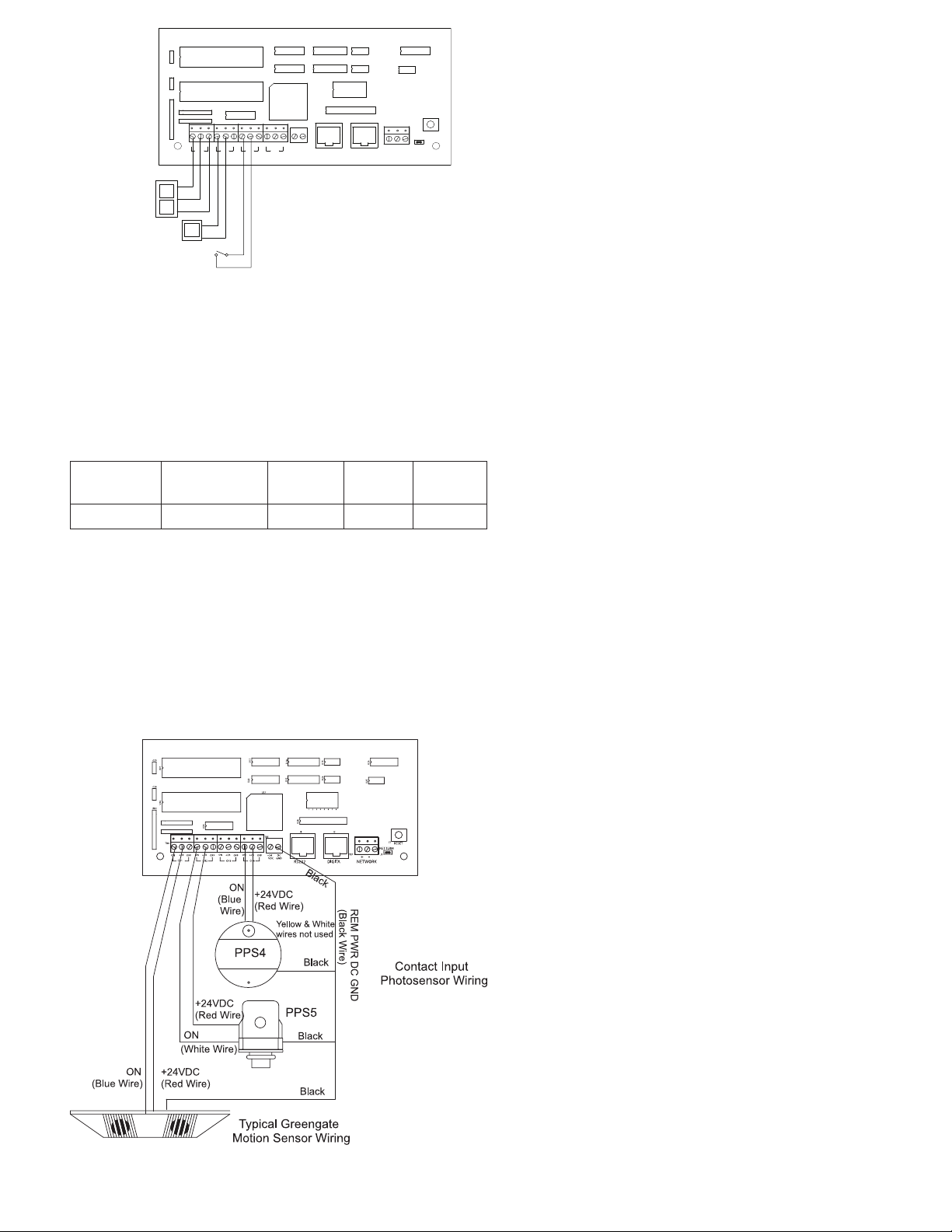
Figure-3 Standard Relay Card Wiring
-+
NETWORKDIGITARS232
VDCDCGND
+24
CH4
OFF
ON +24
CH3
OFF
ON +24
CH2
OFF
ON +24
CH1
OFFON
+24
RESET
NET TERM
U28
U25
U26
U22
U24
U19
U20
U29
TB7
41235687
J2J1
U18
U27
U23
U21
TB5
TB4
S7
RN1
J3
C26
C20
U17
ON
+24VDC
OFF
Momentary Switch
(3 wire)
Toggle Switch
(2 wire)
Maintained Switch
(2 wire)
+24VDC
ON
ON
+24VDC
Contact Input Photosensor and Greengate Sensor Note
It is possible to use a contact input photosensor and Greengate
Motion Sensors in conjunction with the lighting control system. The
ControlKeeper-4 is capable of powering a number of these devices.
Please refer to the chart below for details on how many devices the
transformer can support
Greengate
PIR Sensor
40
Greengate
Dual-Technology
Sensor
16
Greengate
Ultrasonic
Sensor
20
PPS-4
Indoor
Photosensor
20
PPS-5
Outdoor
Photosensor
4
Please contact technical support if it is necessary to power
additional sensors beyond the numbers listed above. These
gures do not account for additional devices such as Digital
Switches being used. If using a combination of devices, please
contact technical support for exact details on how many devices
the logic panel can power.
Photosensor and Motion Sensor Wiring
Digital Switch Wiring
Each ControlKeeper-4® panel is capable of supporting up to 7
Digital Switch device stations and 1 GDS-I gateway device (the
number the controller is able to support is dependent on the
number of other low voltage devices wired that require power
from our logic board. Please contact Technical Support for
exact details of how many devices your logic board can
power.)
Digital Switch cable type should be Cooper LC Cable,
Belden 1502R (non-plenum), or Belden 1502P (plenum).
For best network performance, one of the suggested cables
should be used. If the specied cable is not used and communications problems occur that require troubleshooting
assistance, additional charges for support may be assessed.
Digital Switches do not wire directly to the ControlKeeper-4®
panel, but are wired to a CAN Bus network that connects to the
ControlKeeper-4® through a GDS-I device. Digital Switch
devices should be networked together in a daisy chain conguration. No T-Taps/Stars should be used. The GDS-I device
should reside somewhere within the daisy chain switch net
work. Total daisy chain network length should not exceed
1000 feet.
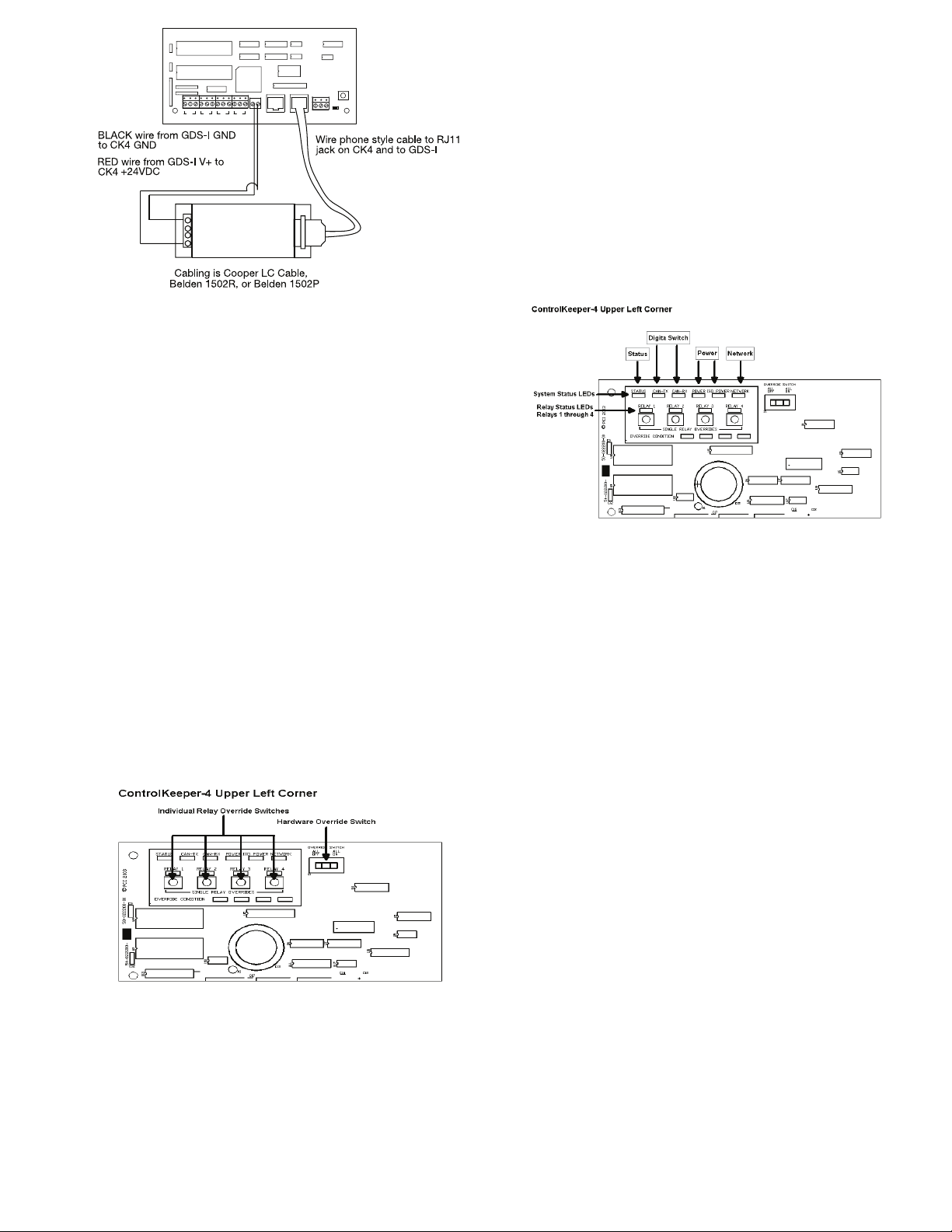
The following instructions describe the GDS-I device connection to the ControlKeeper-4®. Please refer to the Digital Switch
Installation Instructions for information on wiring the Digital
Switch network to the GDS-I.
1. Mount the GDS-I next to the ControlKeeper-4® panel. A
six foot phone style cable has been provided for connec tion to the ControlKeeper-4® panel.
2. Run a length of the Digital Switch LC or Belden cabling
from the GDS-I location to the low voltage section of the
ControlKeeper-4®.
3. Connect the RED wire in the cable to the +V terminal on
the back of the GDS-I and to the ControlKeeper-4® at
one of the switch input +24VDC terminals.
4. Connect the BLACK wire in the cable to the GND termi-
nal on the back of the GDS-I and to the ControlKeeper-4®
remote power connector GND terminal.
5. Tape back or cap the blue and white wires and shield
wire for the cable. They will not be used for connection
between the GDS-I and lighting controller.
6. Locate the 6 foot phone style cable included in the GDS-I
box. Run this from the GDS-I into the low voltage section
of the ControlKeeper-4® enclosure plugging the end with
9 pin head into the GDS-I. Plug the end the RJ11 phone
style plug into the ControlKeeper-4®.
Page 4
Page 5
C20
U21
C26
U26
RN1
TB4
+24
CH1
U17
U18
U23
U22
U27
U29
ON +24
ON +24
OFFON
OFF
CH3
CH2
U28
TB5
ON +24
OFF
OFF
+24
VDCDCGND
CH4
U20
U19
U24
U25
41235687
J2J1
S7
RESET
NET TERM
TB7
J3
-+
NETWORKRS232
GDS-I
Figure-8 GDS-I Wiring Detail
Applying Power
1. After wiring is complete, make certain to clean panel of all
wire clippings and fragments ensuring that no fragments
get lodged between the circuit board and enclosure.
2. Ensure that there are no loose wires or exposed wires that
could short out.
3. Make certain that the line-voltage section of the enclosure
is closed and secure.
4. Power up the unit. It is recommended that the unit be
cleared of all programming unless the unit has been sent
pre-programmed to you by the factory. To perform this step,
hold down the reset button for about 15 seconds.
5. Please refer to the operation section of this instruction for
information on turning on and off lighting loads. Refer to
the Keeper Enterprise Software manual for information
regarding the programming of the ControlKeeper-4.jumper.
Relay Override Operation
The ControlKeeper-4 has two means of override located on the
logic board: individual relay override buttons and a hardware
override switch. It is possible to control lighting loads and
override programming using these override mechanisms.
Figure-10 ControlKeeper-4 Status LEDs
Individual Relay Override Notes
Each relay on the ControlKeeper-4 may be overridden using
the individual relay override switches located at the top left
of the low voltage section. See Figure 9 for location of these
switches. These override switches will toggle the associated
relay’s state with each push of the button. This type of over
ride is temporary in that the override will last until the next
command that the relay is given.
Page 5
Hardware Override Switch Notes
In addition to the individual relay override switches, there is a
hardware override switch that allows the override of all relays
on the board. If this switch is moved to the ALL ON or ALL OFF
position, all four relays will remain ON or OFF as long as the
switch is in that ALL ON or ALL OFF position. The ON or OFF
state is maintained regardless of programmed state. In order
for relays to run programmed scheduling the hardware override
switch must be in the AUTO or center position. See Figure 9
for location of the hardware override switch.
LED Operation
The ControlKeeper-4 has LEDs for status monitoring. They
consist of System Status LEDs and Relay Status LEDs.
Figure-10 ControlKeeper-4 Status LEDs
System Status LEDs
There are six (6) system status LEDs that are located in the
upper left corner of the ControlKeeper-4. Please refer to Figure 10 for location of these status LEDs. These status LEDs
will indicate proper operation or potential problems with the
ControlKeeper-4. Normal Operation includes the following
LED states.
Status LED: The Status LED will ash ON and OFF continuously under normal operation. The LED is an indication of
microprocessor health. If the LED is ON or OFF all the time,
please use the soft reset button on the controller. If the LED
does not resume normal ashing state, contact Technical
Support.
Digital Switch LEDs: These LEDs, labeled CAN-TX and
CAN-RX, will ash when Digital Switch information is being
passed back and forth between the Digit Switch Gateway and
the ControlKeeper-4.
Power LEDs: These LEDs, labeled POWER and ISO POWER,
indicate that the ControlKeeper-4 is getting the proper expected
voltage from the transformer. If one or both of these LEDs is not
lit, there is a problem with power to the board. Please contact
Technical Support for further details.
Network LED: The Network LED should ash only when activity is present on the network wire. If communications commands are not being transmitted over the network wire from
the Keeper Enterprise Software or broadcast switches and this
LED is ickering, ON constant, or ashing, it is an indication
of noise on the network wire that may interfere with proper
system operation. Please check all network wiring carefully for
shorts to AC Ground if this condition exists. Contact Technical
Support for further troubleshooting help.
Page 6

Relay Status LEDs
There are four relay status LEDs, one for each of the relays
on the ControlKeeper-4. Please refer to Figure 10 for location
of these LEDs. The relay status LEDs are an indication of
whether the associated relay is energized or de-energized. If
the relay LED is ON, the relay load should be ON. If the relay
LED is OFF, the relay load should be OFF.
ControlKeeper-4 RS232 Port
The ControlKeeper-4 has an on board RS232 port for communications to peripheral accessory devices or to the Keeper
Enterprise Software. This RJ style jack should not be connected
to any device not intended for use with the lighting control
system. Connection to a phone line will cause damage to the
lighting control system that is not covered under warranty.
Please use only Greengate approved device connections for
connection to this port.
System Reset and Clear Commands
Under certain circumstances, you may want to reset the ControlKeeper-4. There are two different types of reset commands
available in the ControlKeeper-4 system: a soft reset command
and a clear reset command.
Soft Reset Command: A soft reset command is used to initialize a new panel address with the panel. It can also be used
as a troubleshooting technique if the panel is not responding
or to free up the microprocessor if the unit’s STATUS LED is
not ashing. The Soft Reset Command will not cause loss of
panel programming. To perform a Soft Reset Command, press
in and then immediately release the reset button in the lower
right corner of the logic panel. When the reset button is pressed
and released, the status LED may hesitate briey then resume
normal operation.
Clear Settings Command: A clear settings command is used
to remove all programming from a ControlKeeper-4 unit. It
should be done before downloading programming to the unit
for the rst time or when asked to by a Technical Support
representative. Please use caution with this command! When
performing a Clear command, all relay loads will turn off. Use
the Hardware Override Switch to keep lighting on if necessary.
In order to reprogram the unit, you will need to use the Keeper
Enterprise Software. To perform a Clear Command, press and
hold down the reset button in the lower right corner of the lowvoltage section for a period of 15 seconds until the STATUS
LED turns off. Once the STATUS LED turns off, release the
reset button. The ControlKeeper-4 unit will be reset back to
factory default settings.
Programming the ControlKeeper-4
The ControlKeeper-4 is programmed using Keeper Enterprise
Software. Please refer to the Keeper Enterprise Manual for
programming details. It is recommended that a Clear Command
be performed on the controller before the rst programming
download to clear any test data that may be left in the controller
from factory testing.
Repair Information
If a repair becomes necessary on your ControlKeeper-4 unit,
please refer all service to Greengate’s technical support line
at 1-800-553-3879. The ControlKeeper-4 contains no user
serviceable parts.
Page 6
Page 7
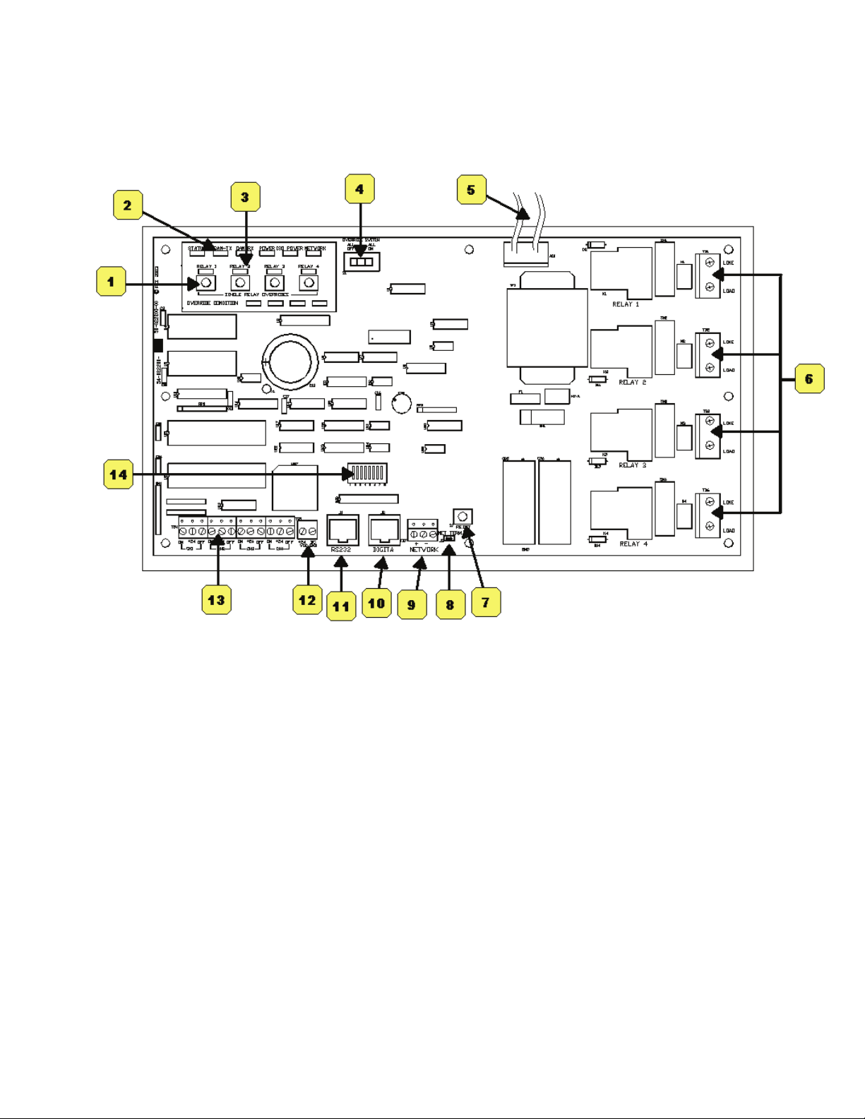
Item Reference
The ControlKeeper-4 consists of a logic board with a clear separation of line-voltage and low voltage components. There are
several features of note on the logic board as pointed out in the below item reference diagram.
Figure-11 Item Reference
1. Individual Relay Override Switches (temporary override)
2. System Status LEDs
3. Relay Status LEDs
4. Panel Hardware Override Switch (ALL OFF, AUTO, ALL ON)
5. Transformer Wiring Leads: White = Neutral, Orange = 277V, Black = 120V
6. Relay Wiring Terminals
7. Panel Reset Switch
8. Network Terminator Jumper
9. Network Wiring Terminal Block
10. Digital Switch Port
11. Panel Communications Port
12. Peripheral Power Terminal: +24VDC, DC Ground
13. Switch Input Wiring Channels
14. Panel Network Address DIP Switches
Page 7
Page 8

All products manufactured by Cooper Controls and identified with the Greengate brand are warranted to be free from defects in material and workmanship and
shall conform to and perform in accordance with Seller’s written specifications for a period of :
• Five (5) years from date of shipment for all occupancy sensors.
• Three (3) years from date of factory invoice for our hardware and software on Lighting Control Panels.
• We warranty all our standard relays for a period of 10 years from date of factory invoice. We guarantee the performance of our system to specifications or your
money back.
This warranty will be limited to the repair or replacement, at Seller’s discretion, of any such goods found to be defective, upon their authorized return to Seller. This
limited warranty does not apply if the goods have been damaged by accident, abuse, misuse, modification or misapplication, by damage during shipment or by
improper service. There are no warranties, which extend beyond the hereinabove-limited warranty, INCLUDING, BUT NOT LIMITED TO, THE IMPLIED WARRANTY
OF MERCHANTABILITY AND THE IMPLIED WARRANTY OF FITNESS.
No employee, agent, dealer, or other person is authorized to give any warranties on behalf of the Seller or to assume for the Seller any other liability in connection
with any of its goods except in writing and signed by the Seller.
The Seller makes no representation that the goods comply with any present or future federal, state or local regulation or ordinance. Compliance is the Buyer’s responsibility. The use of the Seller’s goods should be in accordance with the provision of the National Electrical Code, UL and/or other industry or military standards
that are pertinent to the particular end use. Installation or use not in accordance with these codes and standards could be hazardous.
Cooper Controls
203 Cooper Circle, Peachtree, GA 30269
800-553-3879
www.coopercontrol.com
PArt Number Here
P/N 9850-000230-00
 Loading...