

Page 1
www.crouse-hinds.com US: 1-866-764-5454 CAN: 1-800-265-0502 Copyright©2010 Cooper Crouse-Hinds
462
2C
2C
EDS Series Factory Sealed
Manual Motor Starting Switches
and Enclosures
Cl. I, Div. 1 & 2, Groups B*, C, D
Cl. II, Div. 1, Groups E, F, G
Cl. II, Div. 2, Groups F, G
Cl. III
NEMA 3, 7B*CD, 9EFG
Explosionproof
Dust-Ignitionproof
Raintight
Wet Locations
EDSC2199 EDS2299
Applications:
Factory sealed enclosures are installed in a
rigid metallic conduit system for surface
mounting adjacent to or remote from
equipment being controlled and are used:
• To prevent arcing of enclosed device
from causing ignition of a specific
hazardous atmosphere or atmospheres
external to the enclosure
• In industrial areas such as chemical
plants, oil and gas refineries, paint and
varnish manufacturing plants, gasoline
bulk loading terminals, grain elevators,
grain processing industries, coal
processing or handling areas, or metal
handling or finishing areas where
atmosphere may contain hazardous
gases and/or dust
• In non-hazardous areas where sturdy,
durable enclosures are required
• In conjunction with magnetic starters or
contactors for remote control of motors
Manual motor starting switch enclosures
are used:
• For manual starting of small AC or DC
motors
• To provide manual starting and stopping
and, in the case of units with heaters,
motor running protection
Features:
Factory sealed devices have many distinct
advantages:
• Reduce installation problems
• Eliminate external seals
• Lower installation costs
• Improve safety
• Mounting lugs and taper tapped hubs
with integral bushings
• Large machine screws for fastening
covers to bodies
• Lockout hole for padlock having
1
/4"
hasp is provided
• Close tolerances in machining of wide,
mating flanges and journalled shafts and
bearings produce flametightness of
enclosure joints
• Dead end (EDS) or through feed (EDSC)
hubs –
3
/
4" or 1" sizes
Certifications and
Compliances:
• NEC/CEC
Class I, Division 1 & 2, Groups B*, C, D
Class II, Division 1, Groups E, F, G
Class II, Division 2, Groups F, G
Class III
• NEMA/EEMAC: 3, 7B*CD, 9EFG
• UL Standard: 1203
• CSA Standard: C22.2 No. 30
Standard Materials:
• Bodies – Feraloy®iron alloy (U.S.);
copper-free aluminum (Canada)
• Shafts & bushings – stainless steel
• Sealing enclosures – copper-free
aluminum
Standard Finishes:
Feraloy iron alloy – electrogalvanized and
aluminum acrylic paint
• Copper-free aluminum – natural
• Type 6 / 6 nylon – black
• Stainless steel – natural
Options:
Description Suffix
For use in Group B hazardous
areas
GB*
Bodies and covers (single and two
gang units) – copper-free aluminum
SA
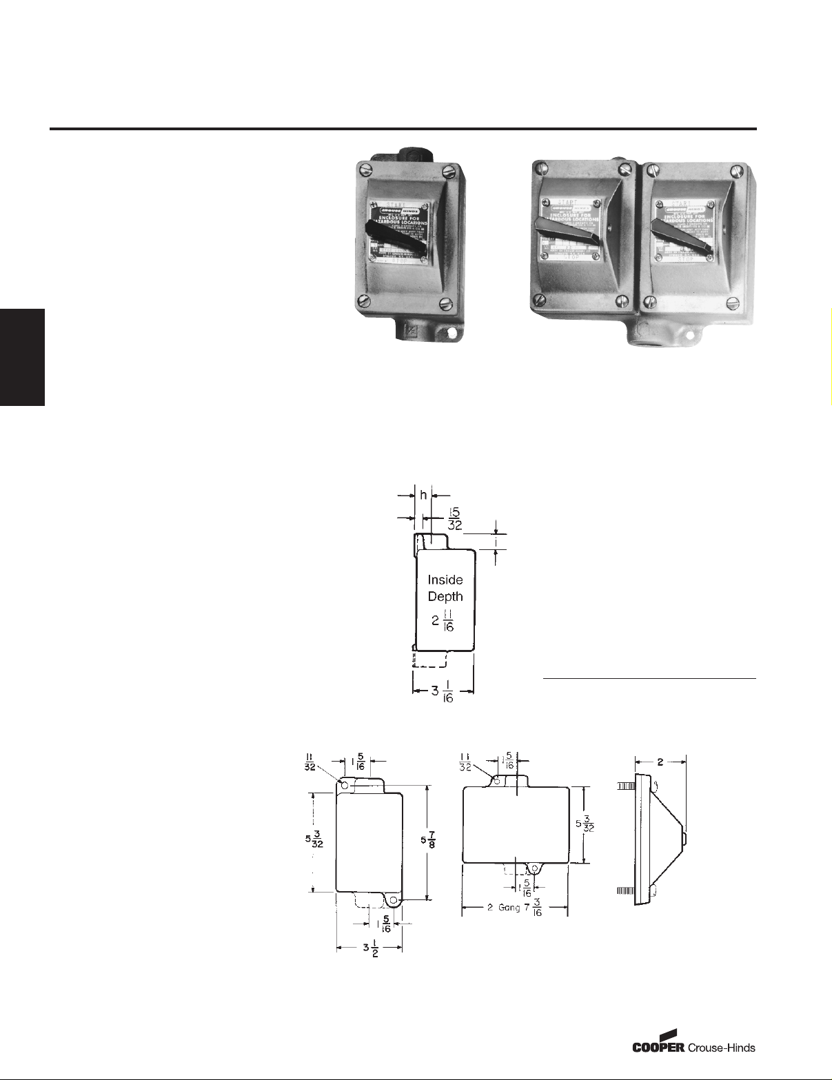
Dimensions
In Inches:
Side View
Front View
Single gang Two gang
Surface covers have same
length and width as single &
2 gang bodies.
Dimensions are approximate, not for construction purposes.
Hub
Size
Dim.
"h"
Dim.
"i"
3
/4
13
/16
1
15
/16
*Seals must be installed within 11/2" of each conduit opening in Division 1.
Page 2

463
www.crouse-hinds.com US: 1-866-764-5454 CAN: 1-800-265-0502 Copyright©2010 Cooper Crouse-Hinds
2C
2C
EDS Series Factory Sealed
Manual Motor Starting Switches
and Enclosures
Ordering Information
With Allen-Bradley Bulletin 600 Switches
Maximum HP Ratings
Poles
115–230
Volts AC
115–230
Votts DC Cat. #
11 hp A B BUL 600 TOX4
21 hp
3
/4 hp A B BUL 600 TOX5
Poles
Hub
Size in. Dead end Cat. # Through feed Cat. #
Single Gang
1
3
/4 EDS2199 ➀ EDSC2199 ➀
1 EDS3199 ➀ EDSC3199 ➀
2
3
/4 EDS21100 ➀ EDSC21100 ➀
1 EDS31100 ➀ EDSC31100 ➀
Two Gang
1
3
/4 EDS2299 ➀ EDSC2299 ➀
1 EDS3299 ➀ EDSC3299 ➀
2
3
/4 EDS22100 ➀ EDSC22100 ➀
1 EDS32100 ➀ EDSC32100 ➀
Heater Table (Allen-Bradley)
Max. Motor
Full-Load
Amps
Crouse-Hinds
Symbol Number
Max. Motor
Full-Load
Amps
Crouse-Hinds
Symbol Number
0.17 P1 2.92 P22
0.21 P2 3.09 P23
0.25 P3 3.32 P24
0.32 P4 3.77 P25
0.39 P5 4.16 P26
0.46 P6 4.51 P27
0.57 P7 4.93 P28
0.71 P8 5.43 P29
0.79 P9 6.03 P30
0.87 P10 6.83 P31
0.98 P11 7.72 P32
1.08 P12 8.24 P33
1.19 P13 8.9 P34
1.30 P14 9.6 P35
1.43 P15 10.8 P36
1.58 P16 12.0 P37
1.75 P17 13.5 P38
1.88 P18 15.2 P39
2.13 P19
2.40 P20
2.58 P21
With General Electric Switches
Maximum HP Ratings
Poles
115–230
Volts AC
115
Votts DC
230
Votts DC Cat. #
1 1 hp 1 hp
1
/4 hp GE CR101 Y
2 1 hp 1 hp 1 hp GE CR101 H
Poles
Hub Size
in. Dead end Cat. # Through feed Cat. #
Single Gang
1
3
/4 EDS21093 ➀ EDSC21093 ➀
1 EDS31093 ➀ EDSC31093 ➀
2
3
/4 EDS21094 ➀ EDSC21094 ➀
1 EDS31094 ➀ EDSC31094 ➀
Two Gang
1
3
/4 EDS22093 ➀ EDSC22093 ➀
1 EDS32093 ➀ EDSC32093 ➀
2
3
/4 EDS22094 ➀ EDSC22094 ➀
1 EDS32094 ➀ EDSC32094 ➀
Heater Table (General Electric)
Max. Motor
Full-Load
Amps
Crouse-Hinds
Symbol Number
Max. Motor
Full-Load
Amps
Crouse-Hinds
Symbol Number
.48 G2 3.01 G22
.53 G3 3.27 G23
.58 G4 3.56 G24
.65 G5 3.88 G25
.71 G6 4.22 G26
.78 G7 4.60 G27
.86 G8 5.00 G28
.95 G9 5.43 G29
1.04 G10 5.90 G30
1.14 G11 6.41 G31
1.25 G12 6.98 G32
1.37 G13 7.60 G33
1.49 G14 8.25 G34
1.63 G15 8.95 G35
1.78 G16 9.75 G36
1.95 G17 10.6 G37
2.13 G18 11.4 G38
2.32 G19 12.5 G39
2.53 G20 13.6 G40
2.76 G21 14.8 G41
16.0 G42
Cl. I, Div. 1 & 2, Groups B*, C, D
Cl. II, Div. 1, Groups E, F, G
Cl. II, Div. 2, Groups F, G
Cl. III
NEMA 3, 7B*CD, 9EFG
Explosionproof
Dust-Ignitionproof
Raintight
Wet Locations
*Add GB suffix. Seals must be installed within 11/2" of each conduit opening for Group B usage.
➀ Includes one interchangeable heater. Select heater from the table
below individual listings and use symbol number as second section
of the Cat. No. Example: EDS2199-P5. Insert symbol 0 (zero) to omit
heater.
These heaters are for motors rated 40°C continuously. For motors
rated 50°C or 55°C, multiply full load motor current by 0.9 and use
this value to select heaters. Symbol 0 (zero) must be used to indicate
heater omitted.
Page 3

www.crouse-hinds.com US: 1-866-764-5454 CAN: 1-800-265-0502 Copyright©2010 Cooper Crouse-Hinds
464
2C
Heater Table (Cutler-Hammer)
Max. Motor
Full-Load
Amps
Crouse-Hinds
Symbol Number
Max. Motor
Full-Load
Amps
Crouse-Hinds
Symbol Number
.43 W 1 2.95 W21
.48 W 2 3.27 W22
.53 W 3 3.59 W23
.58 W 4 3.99 W24
.64 W 5 4.39 W25
.71 W 6 4.79 W26
.78 W 7 5.26 W27
.87 W 8 5.83 W28
.95 W 9 6.39 W29
1.03 W10 7.03 W30
1.15 W11 7.74 W31
1.27 W12 8.46 W32
1.35 W13 9.35 W33
1.51 W14 10.30 W34
1.67 W15 11.35 W35
1.83 W16 12.47 W36
1.99 W17 13.67 W37
2.23 W18 15.12 W38
2.47 W19 16.00 W39
2.71 W20
➀ Includes one interchangeable heater. Select heater from the table
below individual listings and use symbol number as second section
of the Cat. No. Example: EDS2199-P5. Insert symbol 0 (zero) to omit
heater.
These heaters are for motors rated 40°C continuously. For motors
rated 50°C or 55°C, multiply full load motor current by 0.9 and use
this value to select heaters. Symbol 0 (zero) must be used to indicate
heater omitted.
*Add GB suffix. Seals must be installed within 11/2" of each conduit opening for Group B usage.
2C
EDS Series Factory Sealed
Manual Motor Starting
Switches and Enclosures
Cl. I, Div. 1 & 2, Groups B*, C, D
Cl. II, Div. 1, Groups E, F, G
Cl. II, Div. 2, Groups F, G
Cl. III
NEMA 3, 7B*CD, 9EFG
Explosionproof
Dust-Ignitionproof
Raintight
Wet Locations
With Cutler-Hammer Switches
Maximum HP Ratings
Poles
120–240
Volts AC32Volts DC
120
Volts DC
240
Volts DC Cat. #
11 hp
1
/4 hp
1
/4 hp
1
/4 hp WEST MST01
21 hp1/4 hp 1 hp
3
/4 hp WEST MST02
Poles Hub Size in. Dead end Cat. # Through feed Cat. #
Single Gang
1
3
/4 EDS21101 ➀ EDSC21101 ➀
1 EDS31101 ➀ EDSC31101 ➀
2
3
/4 EDS21102 ➀ EDSC21102 ➀
1 EDS31102 ➀ EDSC31102 ➀
Two Gang
1
3
/4 EDS22101 ➀ EDSC22101 ➀
1 EDS32101 ➀ EDSC32101 ➀
2
3
/
4
EDS22102 ➀ EDSC22102 ➀
1 EDS32102 ➀ EDSC32102 ➀
 Loading...