

Page 1
PH-12
Pipe Hangers & Supports
Beam Clamps, Pipe Hangers, Pipe Clamps, Pipe Rollers & Roller
Supports, Pipe Supports-Guides-Shields-Saddles, Seismic Fittings,
Upper Attachments, Threaded Accessories, Concrete Inserts,
Brackets, Vibra Trol
™
, Roof-Top Supports, KwikWire
™
Page 2

Introduction
Cooper B-Line™, Inc. is a leading manufacturer and fabricator of metal products used in the support of pipe
and equipment for industrial, residential, commercial, utility, and OEM installations. Cooper B-Line is proud
of the exacting standards of research, design, engineering, and manufacturing that go into each and every
product that comprise our pipe hanger product line. Our customers have access to the most complete
support systems offered in the industry, including pipe hangers, metal framing, cable tray, slotted angle,
seismic bracing, fasteners, telecom, enclosures and anchors.
Many of Cooper B-Line's products are listed by Underwriters' Laboratories, Inc. and FM Global approved for
fire sprinkler system installations. All Cooper B-Line products are manufactured to meet or exceed industry
standards set for their design and manufacture.
Cooper B-Line products are produced in five modern plants consisting of over 1,000,000 square feet. These
facilities are located in Highland, Illinois; Troy, Illinois; Reno, Nevada; Corona, California and Sherman, Texas.
Regional sales and distribution centers are located throughout the United States stocking standard Cooper
B-Line products for quick service and delivery.
This catalog is designed to be helpful to engineers and contractors in the application and selection of pipe
hangers, supports and seismic bracing for construction and maintenance.
If a unique application requires a special product not included in this catalog, Cooper B-Line engineering
personnel are ready to furnish design consultation and realistic material estimates. In addition, sales
representatives with engineering expertise are located throughout the United States and abroad for your
convenience.
WARNING
All hanger products in this catalog are intended for installation and service as illustrated or described. Do not
use them for any purposes other than those described in this catalog. Products that are used for unintended
purposes could fail, resulting in severe personal injury or death.
Examples of misapplications which could cause severe personal injury or death include, but are not limited to:
Using a beam clamp on a beam other than those described in the catalog;
•
• Using concrete inserts as anchors for pulling pipe up to the required elevation;
• Suspending clevis hangers, one under another, which could result in an accumulative load that is greater
than that which the pipe hanger will support.
Cooper B-Line pipe hanger and support products are manufactured in accordance with industry standards.
Our customers should exercise care to use these products properly so as to avoid potential accidents.
Contact Cooper B-Line for assistance with proper installation and use of the products in this catalog.
NOTICE
Cooper B-Line reserves the right to change the specifications, materials, equipment, prices or the
availability of products at any time without prior notice. While every effort has been made to assure the
accuracy of information contained in this catalog at the time of publication, Cooper B-Line is not
responsible for inaccuracies resulting from undetected errors or omissions.
SINCE
1924
Manufacturers Standardization Society
of the
Valve and Fitting Industry, Inc.
ISO 9001:2008
Cooper B-Line
509 West Monroe Street
Highland, Illinois 62249-0326
Phone: 800-851-7415
Fax: 618-654-1917 www.cooperbline.com
Page 3

Table of Contents
Pictorial Index ........................................................................... 3-15
Strut Systems Information
.......................................... 16-17
Technical Data
Materials & Corrosion
Finishes & General Information
Recommended Specifications
.......................................................... 18
.......................... 18-19
............................. 20-25
Beam Clamps
C-Clamps
Bottom Beam Clamps
Top Beam Clamps
Trus Joist & Angle Iron Beam Clamps
................................................................................ 27-33
................................................. 34-41
................................................................... 42
.......... 43-44
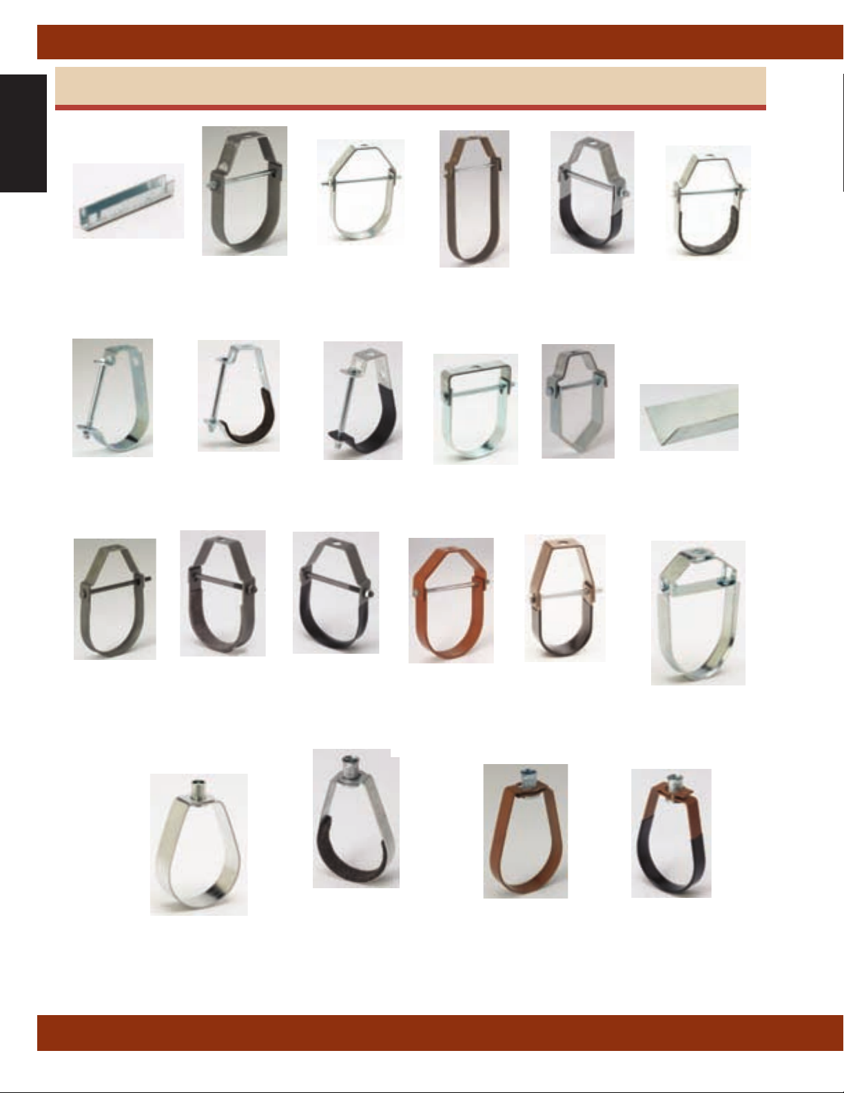
Pipe Hangers
Clevis Hangers
‘J’ Hangers
Band Hangers
Split Clamps & Hangers, Rings
Wall Mount Lay-In Hangers
Wire Hangers
Spring Hangers
................................................................... 47-58
..................................................................................... 53
..................................................................... 59-62
................. 63-66, 72
............................................ 67
....................................................................... 68-70
.......................................................................... 71
Pipe Clamps
Risers
Underground Clamps
Clamps
Straps
CPVC Hangers
Plastic KWIK-CLIP™
.......................................................................................... 75-76
................................................... 77-78
...................................................................................... 79-88
......................................................................................... 89-92
................................................................. 93-101
.............................................. 102-103
Pipe Rollers & Roller Supports
Roller Hangers
Roller Supports
Roller Stands
Spring Cushion Roller Hanger
Rollers
.................................................................................. 120-121
............................................................. 105-106
............................................................ 107-115
................................................................. 116-118
.................................. 119
Pipe Supports, Guides, Shields & Saddles
Calcium Silicate Shields
Stands & Supports
Isolators, Guides & Anchors
Slides, Shields, Saddles
................................................. 123
................................................... 124-138
............................ 139-145
....................................... 146-165
Seismic Bracing
Sway Bracing Pipe Clamps
Sway Bracing Attachments
Mechanical Fast Clamps
Cable Sway Brace Attachments
Sway Brace Main Pipe Attachments
.............................. 167-169
.............................. 170-180
.................................... 181-182
.................. 183-184
....... 185-187
Concrete Inserts
Concrete Deck Inserts
Spot Inserts & Insert Nuts
Continuous Concrete Inserts
Anchor Clips
.............................................................................. 200
.......................................... 189-190
................................. 191-196
.......................... 197-199
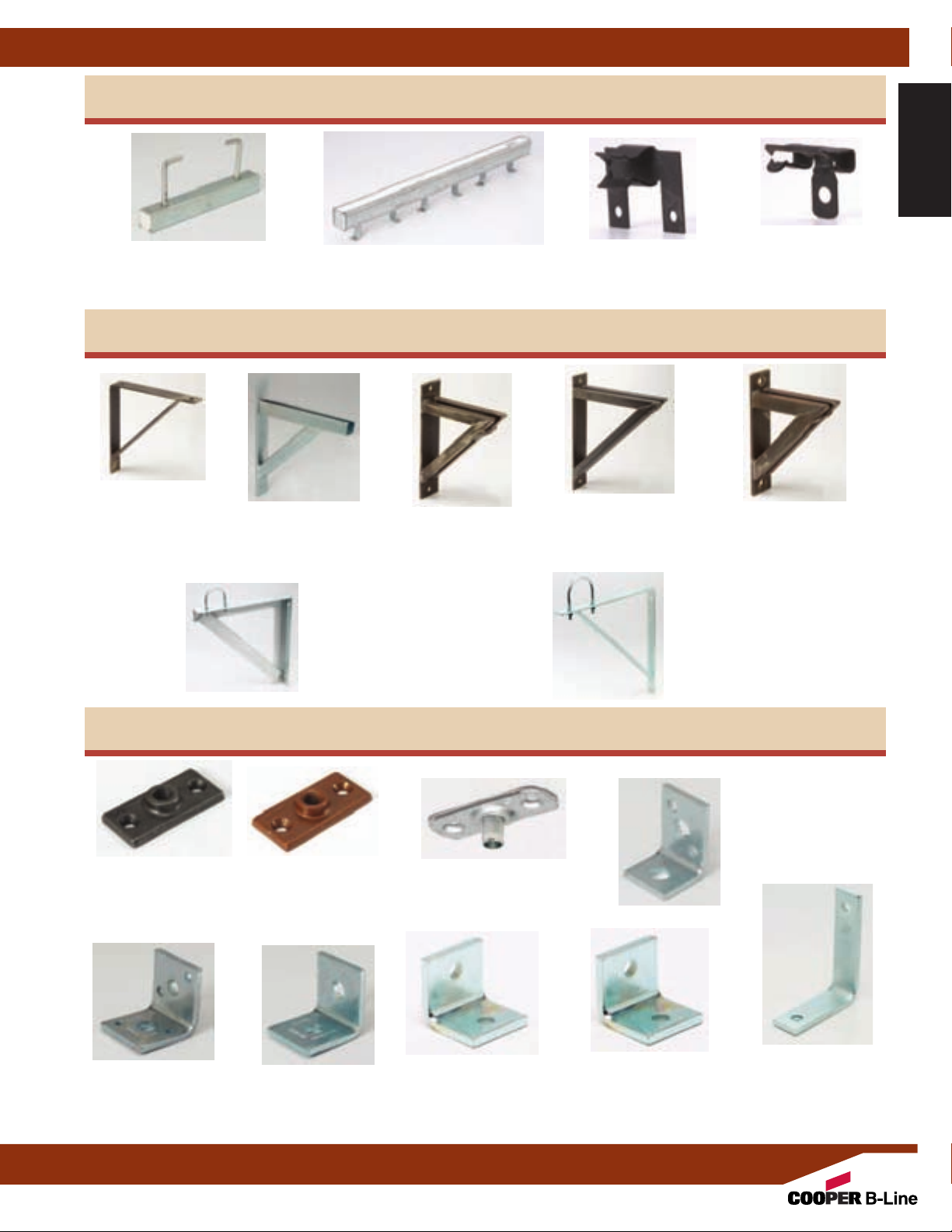
Brackets
Light Duty
Medium Duty
Heavy Duty
Brackets w/ U-Bolts
......................................................................... 203-205
............................................................................. 206
.................................................................................. 207
........................................................... 208
Upper Attachments
Ceiling Flange
Angle Supports
Swivel Attachment
Bolted & Welded
Concrete Plates
Rod Beam Attachments
.......................................................................... 211
............................................................ 212-215
............................................................... 216
......................................................... 217-219
........................................................... 220-222
.................................................. 223
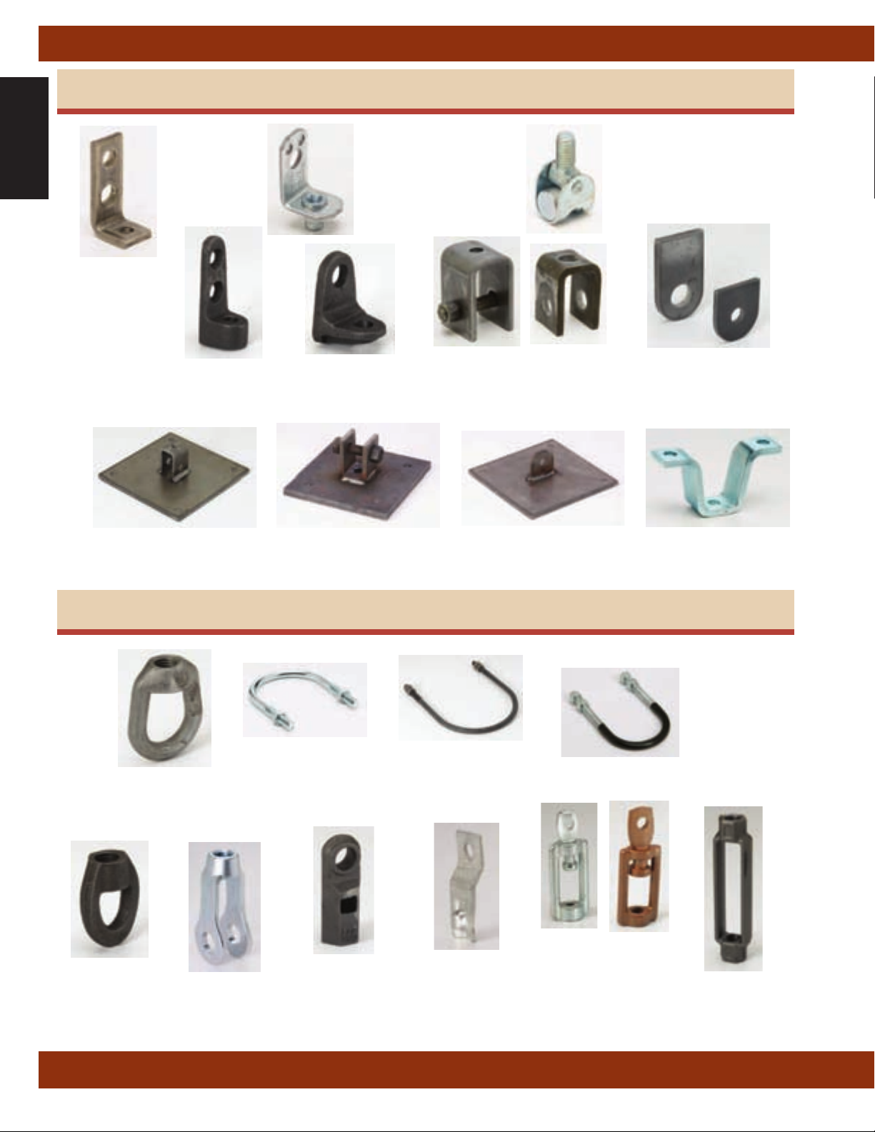
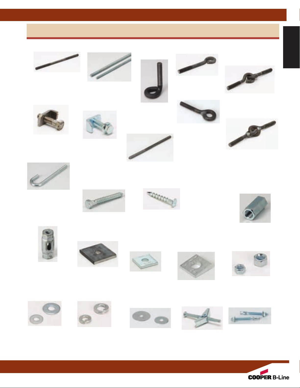
Threaded Accessories
Eye Sockets & Nuts
U-Bolts
................................................................................ 227-229
Miscellaneous Accessories
Rods, Couplings, Washers & Hardware
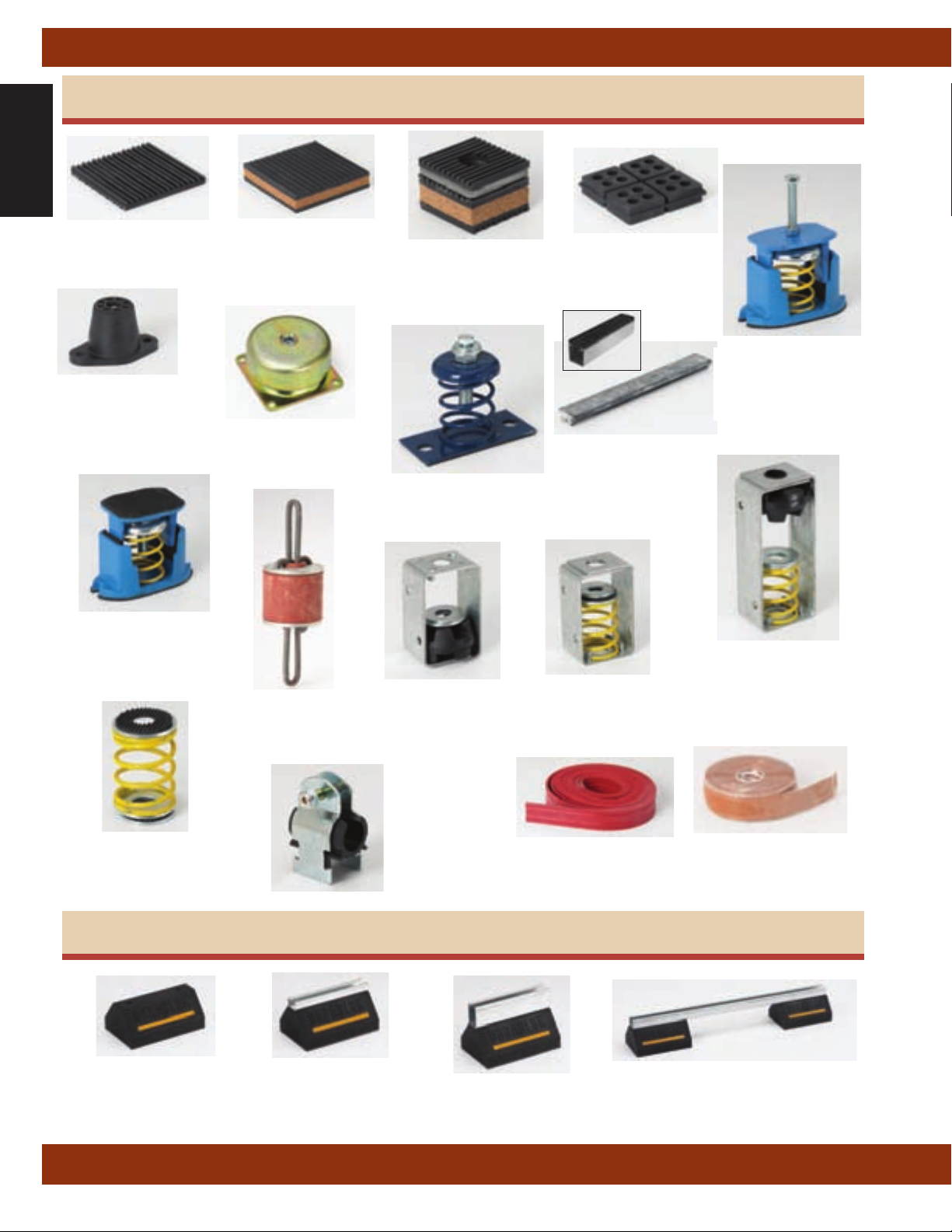
Vibra Trol
™
................................................. 225-226
.............................. 230-232
.......... 233-244
Pads ....................................................................................... 248-250
Molded Mounts
Cup Mounts
Spring Mounts
Vibration Hangers
Spring Hangers
VibraClamp
Isolation Products
DURA-BLOK
....................................................................... 250
................................................................................ 251
.............................................................. 252-257
...................................................... 258-259
............................................................ 260-266
™
.................................................................. 267-268
................................................................ 269
™
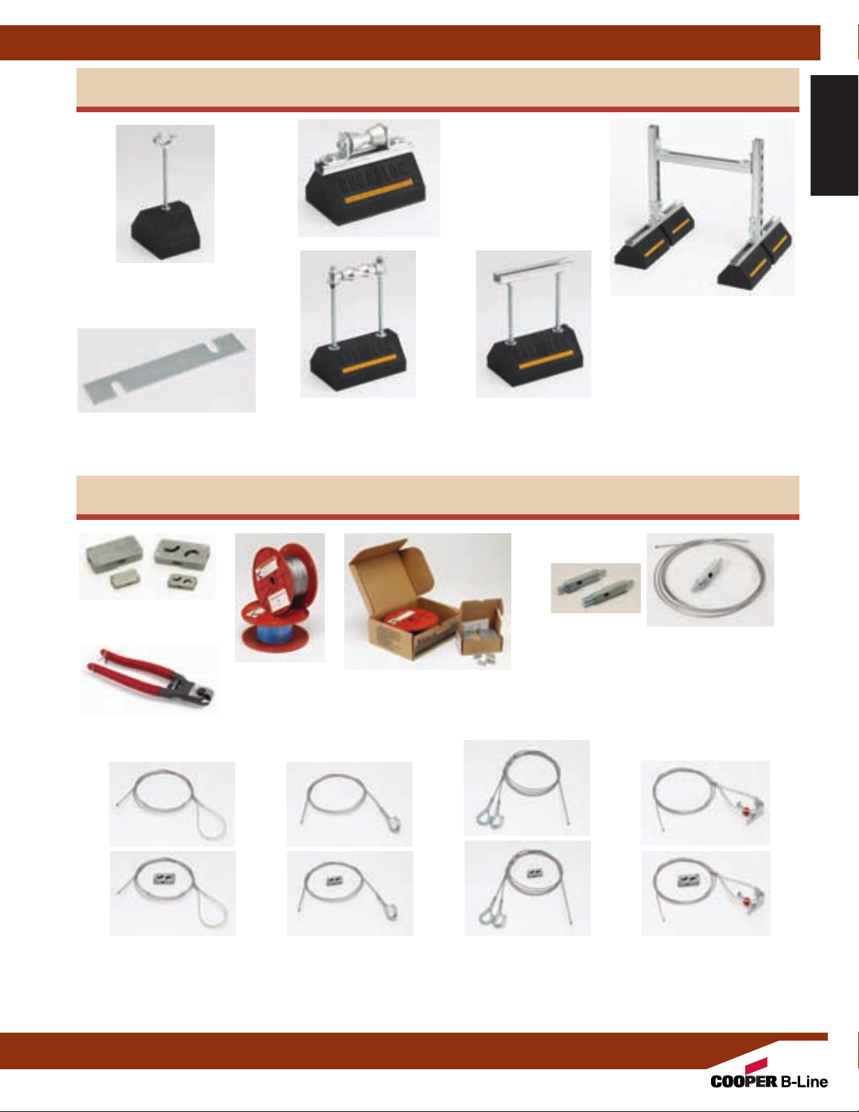
Base .................................................................................................. 271
Base & Channel
Base & Clamp Riser
Base & Harness
Base & Rollers
Base Stand
Load Distribution Plate
KwikWire
™
........................................................... 272-274
........................................................... 275
........................................................... 276-277
.............................................................. 278-279
.................................................................................. 279
.................................................... 280
Clamps ........................................................................................... 283
Wire Rope
KwikPak
Cable Cutter
KwikWire Hangers
.................................................................................... 283
™
Kits ......................................................................... 284
.............................................................................. 284
............................................................... 285
Accessories
(Loop, Hook, Bracket Termination)
........ 286-290
Reference Data
Metric Conversions
............................................................. 292
Miscellaneous Charts
Piping, Tubing, Threaded Rod, etc.
......... 293-303
MSS & Federal Specifications to
B-Line Cross References
B-Line Compliances & Approvals
Trapeze Hanger Chart
.............................. 304-305
............... 306-307
...................................................... 308
Cross References
TOLCO to Cooper B-Line
Cooper B-Line to TOLCO
Anvil/Grinnell to
Erico to
PHD to
Cooper B-Line/TOLCO
Cooper B-Line/TOLCO
Super Strut to
Cooper B-Line/TOLCO
Cooper B-Line/TOLCO
C & P* to Cooper B-Line/TOLCO
Empire to
Cooper B-Line/TOLCO
......................................... 309
.............................. 310-311
........ 312
............................. 313
............................... 314
............. 315
............................... 316
........................ 317
Index ........................................................... 318-320
* C & P is Carpenter & Paterson
1
Page 4
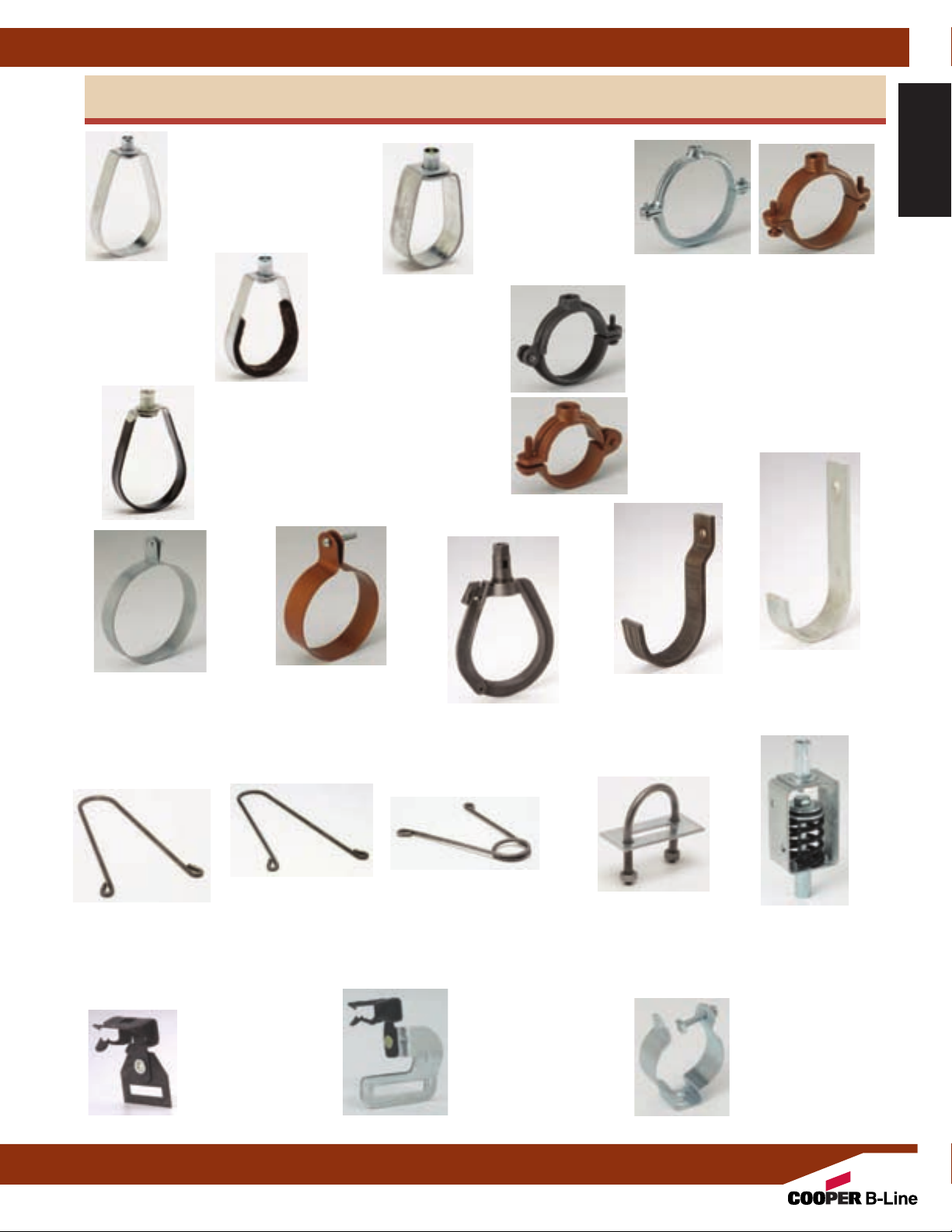
Application Photos
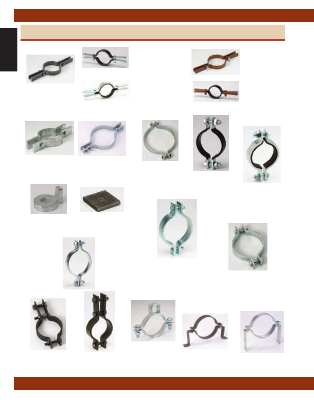
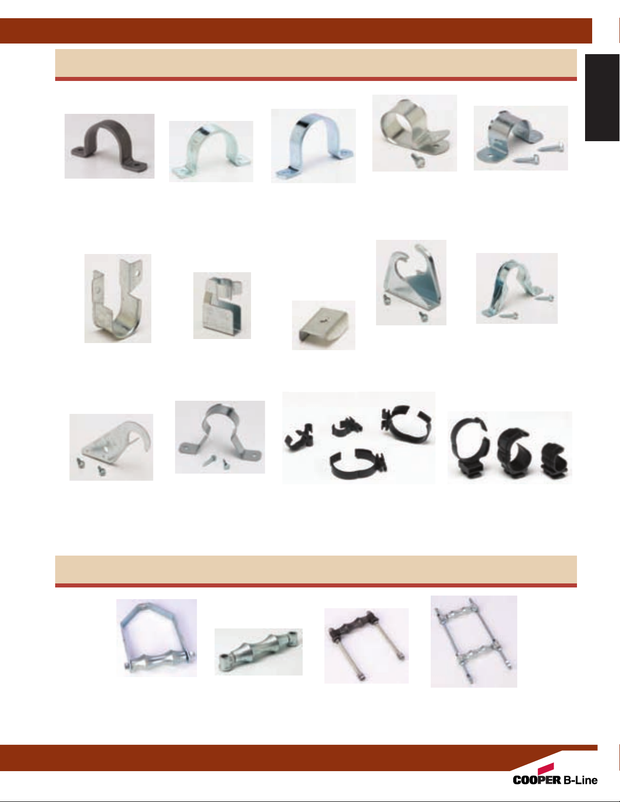
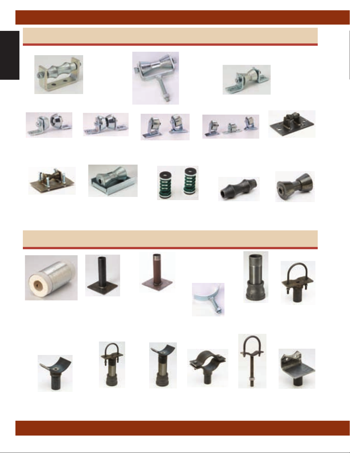
Pictorial Index
2
Page 5
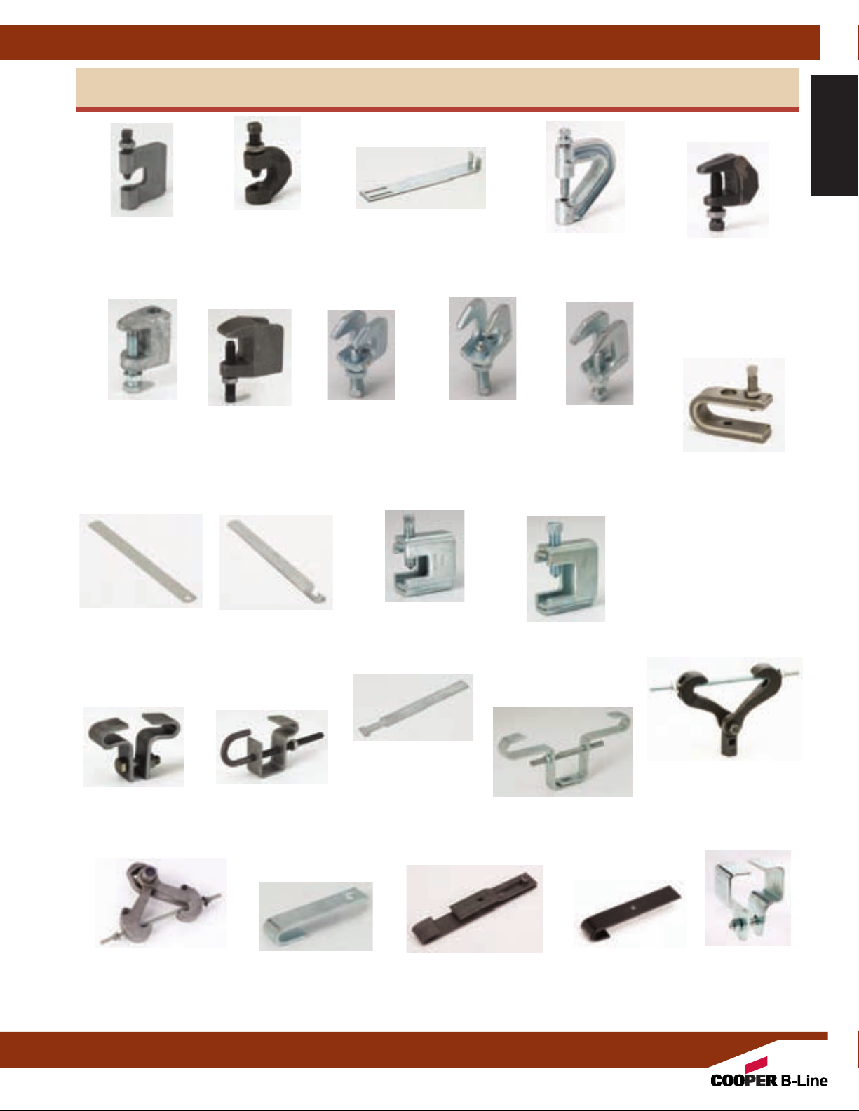
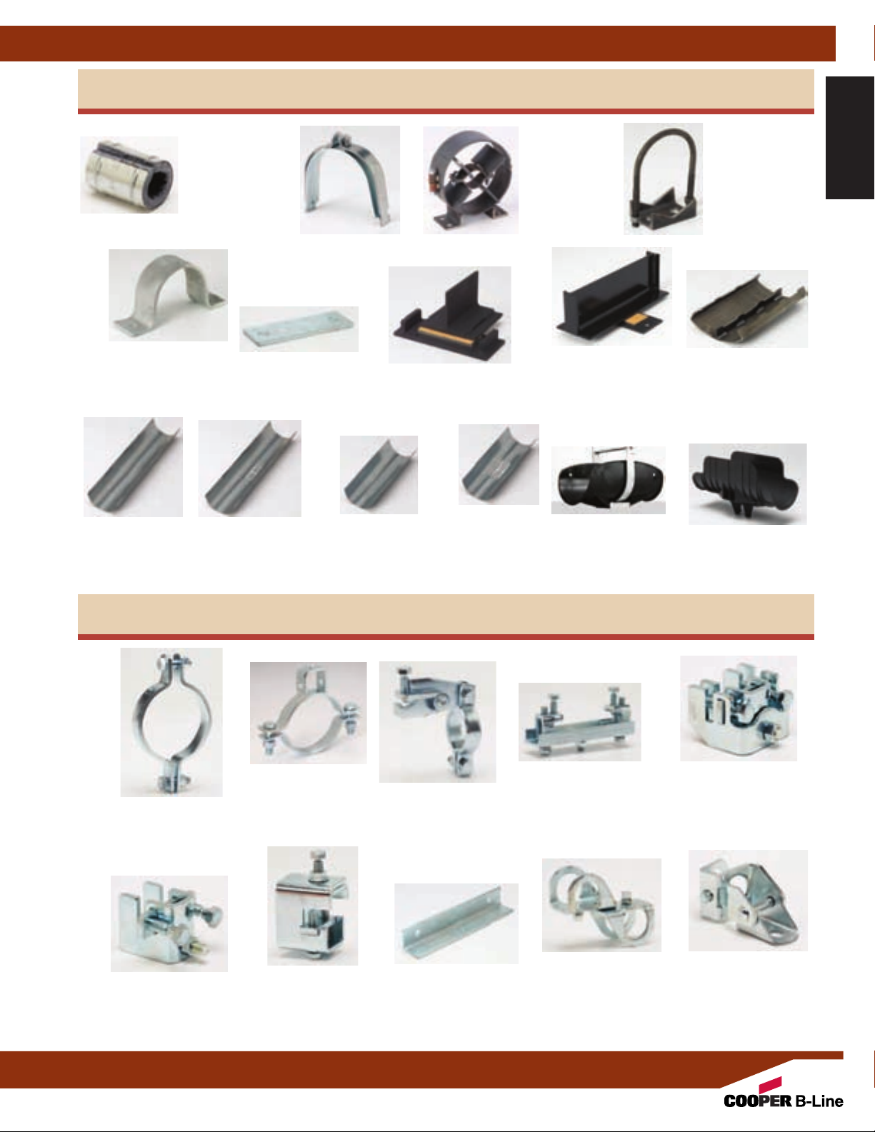
Beam Clamps
Pictorial Index
Pictorial Index
Figure B351L
Steel C-Clamp
With Locknut
Page 27
Figure B3033
Wide Jaw
Top Flange
C-Clamp
Page 29
Figure 69
Retaining Strap
Page 35
Figure B3036L
Malleable Iron
C-Clamp
With Locknut
Page 27
Figure B3034
Top Flange
C-Clamp
Page 30
Figure 69R
Retrofit
Retaining Strap
Page 36
B3362 thru B3365
Retaining Strap
Figure 65
Reversible
Steel C-Clamp
With Locknut
3
/4” Throat
Page 31
Figure B303-B309
Beam Clamp
Figure
Page 28
Figure 65XT-3/8
Steel C-Clamp
With Locknut
Page 34
Reversible
3
/4” Throat
Page 31
Figure B3037
Z-Purlin Beam Clamp
Page 28
Figure 66
Reversible
Steel C-Clamp
With Locknut
1
/4” Throat
1
Page 32
Figure B321 Series
Beam Clamp
Page 34
Figure B3031-3/8
Light Duty
Malleable C-Clamp
Page 29
Figure 67SS
3
(
/4” Throat)
Figure 68SS
1
(1
/4” Throat)
Reversible
Stainless Steel
C-Clamp
With Locknut
Page 33
Figure B3050
Beam Clamp
Page 38
Figure B3291 thru B3298
UFS Forged Steel
Beam Clamp
Page 41
Adjustable Beam Clamp
Figure B3040
Page 38
Figure B3042
Top Beam Clamp
Page 42
Figure B312
Retaining Strap
Page 37
Figure B3045
Side Beam Clamp
3
Page 42
Figure B3055
Steel Beam Clamp
Page 39
Figure B3042T
Bar Joist Hanger
Page 43
Figure B3054
Malleable Iron
Beam Clamp
Page 40
Figure B3052
Trus Joist
Beam Clamp
Page 44
Page 6
Pictorial Index
Pictorial Index
Figure 1CBS
Clevis Pipe Spacer
Figure B3690
Adjustable 'J'
Hanger
Page 53
PIPE HANGERS (Continued)
Figure B3102
AWWA
Clevis Hanger
Page 50
✸
Figure B3690C
Plastic Coated
Adjustable 'J' Hanger
Page 53
Page 47
Figure B3100
Standard
Clevis Hanger
Pages 48 & 49
Figure B3690F
Felt Lined
Adjustable 'J' Hanger
Page 53
Figure B3108
Extended
Clevis Hanger
Page 51
Figure B3109
Flat Top Clevis
Hanger
Page 54
Figure B3100C
Plastic Coated
Standard
Clevis Hanger
Page 52
Figure B3106
Vee Bottom
Clevis Hanger
Page 55
Figure B3100F
Felt Lined
Standard
Clevis Hanger
Page 52
Figure B3106V
Plastic Pipe
Support Channel
Page 55
Figure B3104
Light Duty
Clevis Hanger
Page 56
Adjustable Band Hanger
Figure B3104F
Clevis Hanger
✸
Figure B3170
Page 59
Felt Lined
Light Duty
Page 56
✸ Available in DURA-GREEN
Figure B3104C
Plastic Coated
Light Duty
Clevis Hanger
Page 56
Figure B3170F
Felt Lined
Adjustable Band Hanger
Page 59
◆ DURA-COPPER
™
Finish (Other hangers may be available with the DURA-GREEN finish, contact factory)
Figure B3104CT
Copper Tubing
Light Duty Clevis
Hanger
Page 57
Adjustable Swivel Ring
™
Finish
Figure B3104CTC
Plastic Coated
Copper T
Light Duty Clevis
◆
Figure B3170CT
Copper Tubing
Page 60
Hanger
Page 57
◆
ubing
Figure B3100U
Ultra Clevis Hanger
◆
Figure B3170CTC
Copper Tubing
Plastic Coated
Adjustable Swivel Ring
Page 60
Page 58
4
◆
Page 7
PIPE HANGERS (Continued)
Pictorial Index
Trimline Adjustable
Figure 200F
Felt Lined
rimline Adjustable
T
Band Hanger
Page 61
Figure 200
Band Hanger
Page 61
Figure 200C
Plastic Coated
rimline Adjustable
T
Band Hanger
Page 61
Figure B3198H
Hinged Extension
Split Pipe Clamp
Page 63
Figure B3198HCT
Copper Tubing
Hinged Extension
Split Pipe Clamp
Page 63
◆
Figure 200 H
Heavy Duty
Band Hanger
Page 62
Figure B3198R
Extension
Split Pipe Clamp
Page 64
Figure B3198RCT
Copper Tubing
Extension
Split Pipe Clamp
Page 64
◆
Pictorial Index
Figure B3175
Ring and Bolt Hanger
Page 65
Figure 120
‘U’ Hanger
Page 68
Parallel Strap Hanger
Figure B3175CT
Copper Tubing
Ring and Bolt Hanger
Figure 120MF
Mutt & Jeff
Hanger
‘U’
Page 69
Figure BH-2-4
BH-5-8
BH-9-12
Page 72
Page 65
◆
Figure B3171
Adjustable Split
Ring Swivel Hanger
Page 66
Figure 120W
Wrap Around
Hanger
‘U’
Page 69
Figure BH-2-4-R
BH-5-8-R
BH-9-12-R
Right Angle Strap Hanger
Page 72
Figure B3190
Offset 'J' Hook
Page 67
Figure 120RWA
Retrofit Wrap Around
“u Hanger Clamp
Page 70
Figure B3191
Straight 'J' Hook
Page 67
Figure B3262
Light Duty
Spring Hanger
Page 71
Figure BL1400
thru BL1490
Hanger
Page 72
◆ DURA-COPPER
5
™
Finish
Page 8
Pictorial Index
Pictorial Index
Figure B3373
Standard Riser Clamp
Figure B3132
Two-Bolt
Underground Clamp
Page 77
PIPE CLAMPS
Page 75
Figure B3134
Underground Clamp
Four-Bolt
Page 78
Figure B3373C
Plastic Coated
Standard Riser Clamp
Page 75
Figure B3373F
Felt Lined
Standard Riser Clamp
Page 75
Figure B3140
Standard Pipe Clamp
Page 79
Figure B3140C
Plastic Coated
Standard Pipe Clamp
Page 79
Figure B3373CT
Page 76
Page 76
Page 79
ubing
◆
◆
Copper T
Riser Clamp
Figure B3373CTC
Copper Tubing
Plastic Coated
Riser Clamp
Figure B3140F
Felt Lined
Standard Pipe Clamp
Figure B3132W
Lug Washer
Page 77
Figure B3146
Heavy Duty Double
Bolt Pipe Clamp
Page 83
Figure B3134W
Washer
Page 78
Figure 4A
Pipe Clamp for
Sway Bracing
Page 80
Figure B3144
Double Bolt Pipe Clamp
Pages 84 & 85
Figure B3141
A.W.W.A. Pipe Clamp
Figure 4B
Pipe Clamp For
Sway Bracing
Page 86
◆ DURA-COPPER
Page 81
™
Finish
Figure B3148
Offset Pipe Clamp
Page 87
Figure B3142
Heavy Duty Pipe Clamp
Page 82
Figure B3149
Marine Hanger
Page 88
6
Page 9
PIPE CLAMPS (Continued)
Pictorial Index
Pictorial Index
Figure B3180FL
Flush Mount
Pipe Strap
Page 89
Figure 24
Double Fastener
Side Mounted
CPVC Strap
Page 95
Figure B2400
Standard Pipe Strap
Pages 90-91
Figure 25
Surge Restrainer
Page 96
Figure B3180
Extended Leg
Pipe Strap
Page 92
Figure 27
Speed Nut
Page 97
Figure 22
Single Fastener
CPVC Strap
Page 93
Figure 28
Stand-Off Hanger &
Restrainer for
CPVC Pipe
Page 98
Figure 23
Double Fastener
Strap
CPVC
Page 94
Figure 28M
Offset Hanger &
Restrainer for
CPVC & IPS Pipe
Page 99
Figure 29
Double Offset
Hanger & Restrainer
for CPVC Pipe
Page 100
Figure B3184
Light Duty
fset Hanger &
Of
Restrainer for
CPVC & IPS Pipe
Page 101
Figure BPRC Series
PIPE ROLLERS & ROLLER SUPPORTS
Figure B3110
Adjustable Steel
Yoke Pipe Roll
Page 105
✸
Figure B3114
Pipe Roll With Sockets
Page 106
✸ Available in DURA-GREEN
7
Rod Mount
KWIK-CLIP
Page 102
Figure B3122
Adjustable Roller Support
Page 107
™
Finish
Figure BPIC Series
Figure BPSC Series
Channel Mount
KWIK-CLIP
Page 103
Figure B3122A
Adjustable Double
Roller Guide
Page 108
Page 10
Pictorial Index
Pictorial Index
Adjustable Roller Stand
PIPE ROLLERS & ROLLER SUPPORTS (Continued)
Figure B218
Pipe Rollers
Page 1
Figure B3118SL
With Base Plate
Page 117
12
Figure
B3120
Roller Chair
Page 109
Figure B219
Pipe Rollers
Page 1
Figure B3119SL
Roller With Steel
Base Plate
Page 1
13
18
Figure B3124
Roller Support
Page 1
Figure B379
Pipe Rollers
14
Page 1
Figure B3264
Spring Cushion Hanger
19
Page 1
10
Figure B479
Pipe Rollers
Page 1
Figure B3114R
Long Pipe Roll Only
Page 120
15
Figure B3126
Roller Support
11
Page 1
Figure B3117SL
Steel Roller Stand
16
Page 1
Figure B3117R
Short Pipe Roll Only
Page 121
PIPE SUPPORTS, GUIDES, SHIELDS & SADDLES
Figure B3088T
Threaded Base Stand
Figure B3088ST
Seismic Threaded
Base Stand
Pages 124 & 125
Figure B3093
Adjustable Pipe
Saddle Support
Pages 134 & 135
Figure B3096
Adjustable Pipe
Saddle Support
Page 126
Figure B3097
Pipe Saddle
With Strap
Page 136
Figure B3380
thru B3384
360° Calcium
Silicate Shield
Page 123
Figure B3095
Pipe Saddle Support
Pages 130 & 131
Figure B3088
Base Stand
Figure B3088S
Seismic Base Stand
Pages 124 & 125
Figure B3092
Adjustable Pipe Saddle
Support With Yoke
Pages 132 & 133
Figure B3089
Pipe Support
Adjuster
Page 127
Figure B3098
Adjustable Pipe
Support w/U-Bolt
Page 137
Figure B3090
Pipe Saddle
Support
With U-Bolt
Pages 128 & 129
Figure B3094
Flange Support
Page 138
8
Page 11
Pictorial Index
PIPE SUPPORTS, GUIDES, SHIELDS & SADDLES (Continued)
Figure B3256
Hold-Down
Anchor Clamp
Page 144
Figure B3151
Insulation
Protection Shield
Page 161
Figure B3195
I.P.S. Isolator
Figure B3195CT
Copper Tubing
Isolator
Page 139
Figure B3257
Base Plate
Page 145
Figure B3153
Insulation Protection
Shield With
Page 161
Tabs
Figure B2417
Pipe Guides
Page 142
Figure B3154
Short Insulation
Protection Shield
Page 162
Figure B3891 thru B3897
Pipe Slides
Pages 146 - 149
Figure B3155
Short Insulation
Protection Shield
abs
With T
Page 162
Figure B3281
thru B3287
Pipe Alignment
Guide
Pages
140 & 141
Figure B3991 thru
B3993
Pipe Slides
Pages 150 - 153
Figure BPH Series
Snap N’Shield
Page 163
Clevis
Figure B3147A
Figure B3147B
Anchor Chairs
Pages 142 & 143
Figure B3160 thru
B3165
Pipe Covering
Protection Saddle
Pages 154 - 159
Figure BPS Series
Snap N’Shield
Pages 164 & 165
Pictorial Index
SEISMIC BRACING
Figure 4B
Pipe Clamp For
Figure 4A
Pipe Clamp For
Sway Bracing
Page 167
Figure 825A
Bar Joist Sway
Brace Attachment
Page 172
Sway Bracing
Universal Sway
Brace Attachment
Page 168
Figure 828
Page 173
Figure 4L
Longitudinal “In-Line”
Sway Brace
Attachment
Page 169
Figure 906
Sway Brace Multi-
Fastener Adaptor
Page 174
Figure 800
Adjustable Sway
Brace Attachment
o Steel
T
Page 170
Figure 907
4-Way
Longitudinal Sway
Brace Attachment
Page 175
Figure 825
Bar Joist Sway
Brace Attachment
Page 171
Figure 909
No-Thread Swivel
Sway Brace
Attachment
Page 176
9
Page 12
Pictorial Index
Pictorial Index
Swivel Sway Brace
SEISMIC BRACING (Continued)
Figure 910
Attachment
Page 177
Figure 980
Figure 975
Straight Sway
Brace Fitting
Page 178
Universal Swivel
Sway Brace
Attachment
Page 179
Universal Swivel Sway
Figure 981
Fast-Attach
Brace Attachment
Page 180
Figure 985
Mechanical Fast
Clamp
Page 181
Figure 986
Mechanical Fast
Clamp
Page 182
Figure 990
Cable Sway Brace
Attachment
Page 183
Figure 991
Fast Attach
Cable Sway Brace
Attachment
Page 184
CONCRETE INSERTS
Figure 109A
Concrete Deck Insert
Page 189
Figure B3019
Adjustable Metal
Deck Ceiling Bolt
Page 190
Figure 1000
Fast Clamp
Sway Brace
Attachment
Page 185
Figure 1001
Sway Brace
Attachment
Page 186
Figure 109AF
Spot Insert
Page 191
Figure 2002
Sway Brace
Attachment
Page 187
Figure B2499
Heavy Duty Spot Insert
Page 192
Figure B2500
Light Duty Spot Insert
Page 193
Figure N2500
Steel Insert Nut
Page 193
Figure B3014
Malleable Iron
Spot Insert
Page 194
10
Figure B3014N
Malleable Iron Insert Nut
Page 194
Figure B2505
thru B2508
Spot Insert
Page 195
Page 13
CONCRETE INSERTS (Continued)
Pictorial Index
Pictorial Index
Figure B2503
Heavy Duty Spot Insert
Page 196
BRACKETS
Figure B3068
Light Duty Welded
Bracket
Page 203
Figure B22I, B32I, B52I
Continuous Concrete Inserts
Figure B3064
Adjustable Strut Bracket
Page 204
Figure B3069W
Welded Knee Brace
Page 208
Pages 197 - 199
Figure B3065
Light Duty Welded
Bracket
Page 205
Figure BD40
Fastener Clip
Page 200
Figure B3066
Medium Duty Welded
Bracket
Page 206
Figure BE-5-8
Figure BE-9-12
Fastener Clip
Page 201
Figure B3067
Heavy Duty Welded Bracket
Page 207
Figure B3069E
“O” Bracket
Page 208
UPPER ATTACHMENTS
Figure B3199
Ceiling Flange
Page 21
Figure B3070
Reversible Angle Clip
Page 212
1
Figure B3199CT
Dura-Copper Coated
Ceiling Flange
Page 21
Figure B3060
Side Beam Angle Clip
Page 213
1
◆
Figure 78
All Steel Ceiling Plate
Page 21
Figure 51
Side Beam Angle Clip
Page 213
◆ DURA-COPPER
11
1
™
Finish
Figure 50
Side Beam Bracket For
A Rod & Fastener Sizing
NFP
Page 214
Figure B3060L
Side Beam
Angle Clip
Page 212
Figure B3061
Angle Bracket
Page 214
Page 14
Pictorial Index
Pictorial Index
Figure 56
Tapped Side
Beam Connector
Page 214
UPPER ATTACHMNETS (Continued)
Figure 58
Threaded Side
Beam Bracket
Page 215
Figure B3058
Side Beam Connector
Page 217
Figure B3062
Side Beam Bracket
Page 217
Figure B3083
Figure B3083WO
Welded Beam
Page 218
Attachment
Figure 75
Swivel Attachment
Page 216
Figure B3080S (Short)
Figure B3080L (Long)
Structural Welding Lug
Page 219
Figure B3085
Rod Attachment Concrete Plate
Page 220
THREADED ACCESSORIES
Figure B3200
Weldless Eye Nut
Page 226
Figure B3222
Eye Socket
Page 225
Figure B3201
Forged Steel Clevis
Page 230
Figure B3086
Clevis Concrete Plate
Page 221
Figure B501
Light Weight U-Bolt
Page 227
Figure B3203
Extension Piece
Page 231
Figure B3188
Standard U-Bolt
Pages 153 & 154
Pages 228 & 229
Figure B3223
Offset Eye Socket
Page 231
◆ DURA-COPPER
Figure B3084
Single Lug Concrete Plate
Page 222
Figure B3224
Hanger Adjuster
Figure B3224CT
Dura-Copper Coated
Hanger Adjuster
™
Finish
Page 232
Figure B3082
Rod Beam Attachment
Page 223
Figure B3188C
Plastic Coated
Standard U-Bolt
Pages 228 & 229
Figure B3202
Turnbuckle
Page 232
◆
12
Page 15
THREADED ACCESSORIES (Continued)
Pictorial Index
Pictorial Index
Figure B3205
Machine Threaded Rod
Page 233
Figure 98
Rod Stiffener
Page 234
Figure B3212
J-Bolt
Page 238
Figure ATR
All Threaded Rod
Page 233
Figure 98B
Rod Stiffener with
Break Off Bolt Head
Page 234
Figure B3228
Hex Head Lag Bolt
Page 238
Figure B3214
Tie Bolt
Page 235
Figure B3213
Coach Screw Rod
Page 235
Figure DS 16 x 2
#16 x 2"
Drive Screw
Page 238
Figure B3210
Eye Rod
Page 236
Figure B3210X
Linked Eye Rod
Page 237
Figure B3211
Welded Eye Rod
236
Figure B3211X
Linked Welded Eye Rod
Page 237
Figure B655
Steel Rod Coupling
Page 164
Figure B656
Steel Reducer
Rod Coupling
Page 239
Figure B3220
Malleable Iron
Rod Coupling
Page 240
Figure FW
Flat Washer
Page 243
Figure B3248
Steel Washer Plate
Page 241
Figure LW
Lock Washer
Page 243
Figure B200
Square Washer
Page 240
Figure FFW
Flat Fender Washer
Page 243
13
Figure B3234
Bevel Washer
Page 241
Figure ATB
Toggle Bolt
Page 244
Figure HN - Hex Nut
Figure HHN - Heavy
Hex Nut
Page 242
Figure AWA
Wedge Anchor
Page 244
Page 16
Pictorial Index
Pictorial Index
Ribbed Neoprene Pad
Double Deflection
VIBRA TROL
Figure NNP
Page 248
Figure NVD
Page 250
™
Figure CNP
Cork and Ribbed
Neoprene Pad
Page 248
Figure CM
Metal Housing and Neoprene
Page 251
Figure CNNK
Cork, Ribbed Neoprene
and Steel
Page 249
Figure OML/OM
Spring Mount
Pages 252 & 253
Figure VRP
Rubber Cube Pad
Page 249
Figure BVS
Vibra Strip™
15/8" Wide B-Line
channel
Page 250
for
Figure HMLE/HME
Housed 1"
Deflection Mounting
Pages 254 & 255
Figure HMLT/HMT
Housed 1"
Deflection Mounting
Pages 256 & 257
Figure SHE
Isolation Spring Hanger
Pages 264 & 265
DURA-BLOK
DBP & DBM
Bases
Page 271
Figure ANH
Acoustical Hanger
Page 258
™
DB Series
Base & Short Channel
Page 272
Figure RH
Neoprene Hanger
Page 259
Figure BVT
VibraClamp
ubing Sizes
T
Page 267
Figure BVP
VibraClamp
Pipe Sizes
Page 268
DB6 Series
Base & Tall Channel
Page 273
Figure HSL/HS
Vibration Spring Hanger
Pages 260 & 261
Figure B1999
Vibra Cushion
Page 269
Double Base & Long Channel
Figure HESL/HES
Combination Spring
& Neoprene
Pages 262 & 263
Figure ISO
ISO Pipe
Page 269
DB10 Series
Page 274
14
Page 17
Pictorial Index
DURA-BLOK
DBM Series
Base & Clamp Riser
Page 275
CLDP10
Load Distribution Plate
Page 280
™
(Continued)
DBR Series
Base & Adjustable Height
Roller Assembly
Page 279
DBR Series
Base & Fixed Height
Roller Assembly
Page 278
DBE Series
Base & Adjustable
Height Channel
Page 279
Pictorial Index
DB__DS Series
Bases & Harness Assembly
Pages 276 & 277
KWIKWIRE™
KwikWire Clamp
Page 283
Wire Rope Cutter
Page 284
Wire Rope
Page 283
KwikWire Hanger
Page 285
KwikPak Kit
Page 284
KwikWire Accessories
BKL & BKLK
ermination
Loop T
Page 2867
KwikWire Accessories
BKH & BKHK
Single Hook
Termination
Page 288
15
KwikWire Accessories
BKYH & BKYHK
Double Hook
Termination
Page 289
KwikWire Accessories
BKA & BKAK
Angle Bracket
ermination
T
Page 290
Page 18
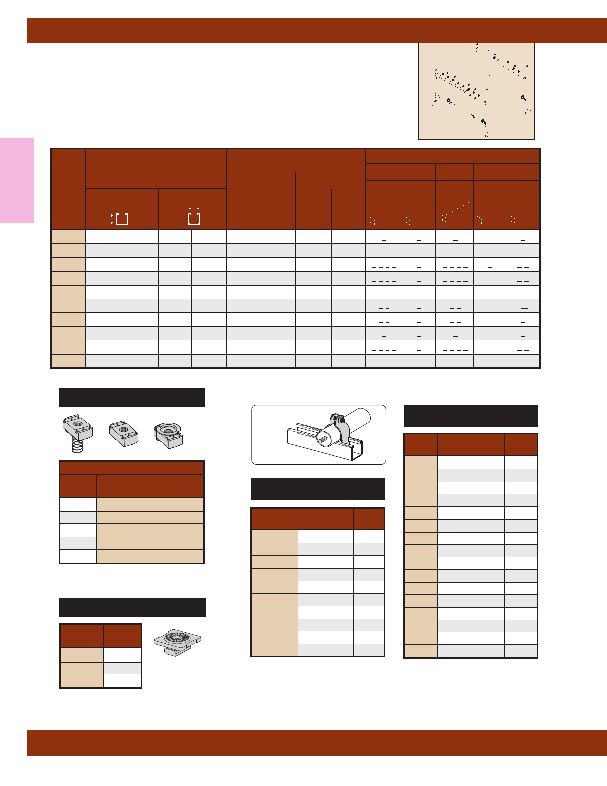
Strut Systems
Cooper B-Line's metal framing support system is designed with many
time-saving features. Fully adjustable and reusable, with a complete line
of channels, fittings, and accessories for multi-purpose applications.
SELECTION CHART
for Channels, Materials and Hole Patterns
Strut Systems
Information
Channel
Type
B11 3
B12 27/16" (61.9) 15/8" (41.3) 12 Ga. .105 -- -- 1 2 1 1 2 -- 1 2
B22 15/8" (41.3) 15/8" (41.3) 12 Ga. .105 12 Ga. 12 Ga. 1 2 3 4 1 1 2 3 4 1 1 2
B24 15/8" (41.3) 15/8" (41.3) 14 Ga. .080 14 Ga. 14 Ga. 1 2 3 4 1 1 2 3 4 -- 1 2
B26 15/8" (41.3) 15/8" (41.3) 16 Ga. -- -- -- 1 1 1 -- 1
B32 13/8" (34.9) 15/8" (41.3) 12 Ga. -- 12 Ga. -- 1 3 1 1 3 -- 1
B42 1" (25.4) 15/8" (41.3) 12 Ga. -- 12 Ga. -- 1 3 1 1 3 -- 1
B52
B54
B56
1
/4" (82.5) 15/8" (41.3) 12 Ga. -- -- -- 1 1 1 -- 1
13
/16" (20.6) 15/8" (41.3) 12 Ga. -- -- -- 1 1 1 -- 1
13
/16" (20.6) 15/8" (41.3) 14 Ga. .080 14 Ga. 14 Ga. 1
13
/16" (20.6) 15/8" (41.3) 16 Ga. -- -- -- 1
Height
Channel
Dimensions
Width
Material & Thickness* Channel Hole Pattern **
Stainless SH S H17/8 TH KO6
Steel
Steel
1
Alum.
2
Type
304
Type
316
3
4
2 3 4 1 1 2 3 4 -- 1 2
1 1 -- 1
Channel Nuts
Size and Part Number
Thread
With Without
Twirl
Size Spring Spring Nut
1
/4"-20 N224 N224WO TN224
3
/8"-16 N228 N228WO TN228
1
/2"-13 N225 N225WO TN225
5
/8"-11 N255 N255WO --
3
/4"-10 N275 N275WO --
Available Finishes: Electro-Galvanized
Combo Nut Washers
Part Thread
Number Size
NW5241/4"-20
NW528
NW525
3
/8"-16
1
/2"-13
Available Finishes: Electro-Galvanized
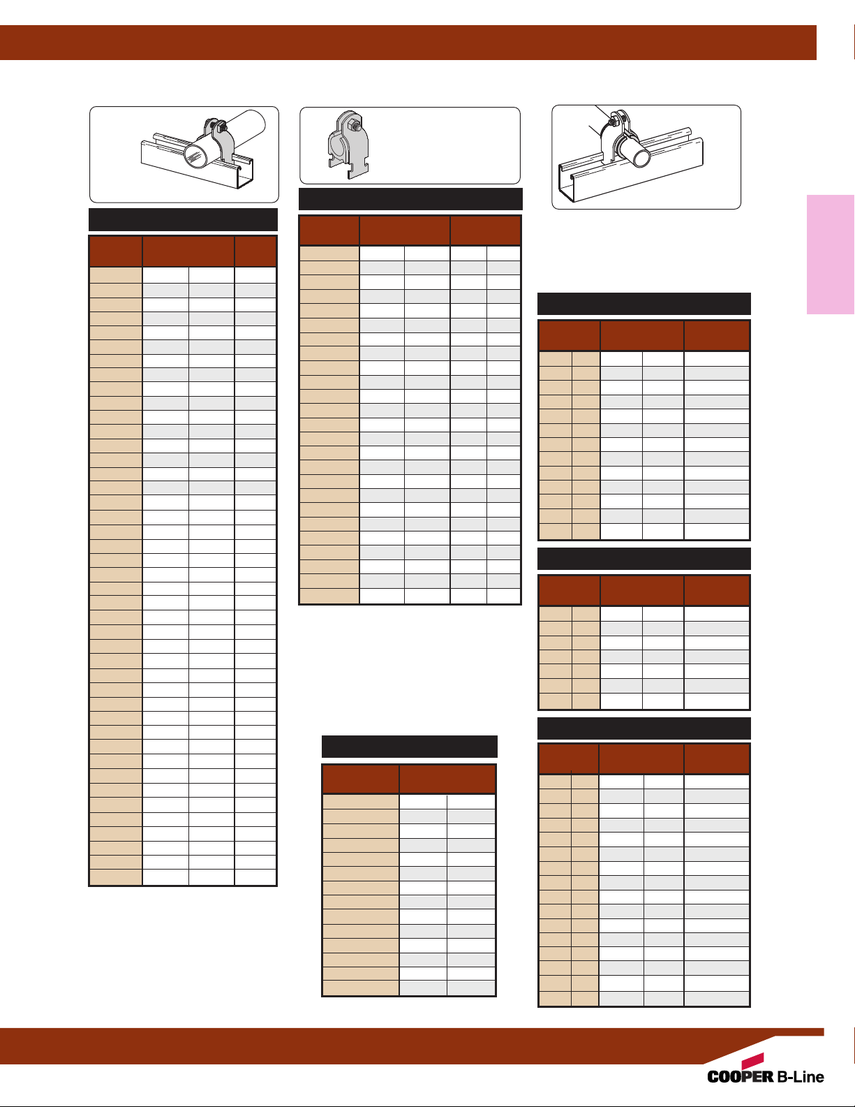
B2000 Series
Schedule 40 Pipe Clamps
Part
Nomina l
No. Pipe Size Ga.
3
/8" (10) 16
1
/2" (15) 16
3
/4" (20) 14
1
/4" (32) 14
1
/2" (40) 12
1
/2" (60) 12
1
/2" (90) 11
1
/2" (115) 11
Copper Tubing Clamps
DURA-COPPER
Part
No. Tubing Size Ga.
B2026DCU1/2" (15) 16
B2008DCU
B2030DCU 1"
B2032DCU 1
B2011DCU 1
B2038DCU 2"
B2042DCU 2
B2046DCU 3"
B2050DCU 3
B2054DCU 4"
Nominal
3
/4" (20) 16
1
/4" (32) 14
1
/2" (40) 14
1
/2" (60) 12
1
/2" (90) 12
™
Mat'l
(25) 14
(50) 12
(80) 12
(100) 11
B2001
B2008
B2009
B2010 1"
B2011 1
B2012 1
B2013 2"
B2014 2
B2015 3"
B2016 3
B2017 4"
B2018 4
B2019 5"
B2020 6"
B2021 7"
B2022 8"
Available Finishes: Electro-Galvanized, Aluminum, Stainless,
Dura-Copper Painted, Hot-Dip Galvanized and PVC coated.
Nut and bolts are included with all two-piece clamps.
** Add “PA” to Part No. for Pre-assembled
Mat'l
(25) 14
(50) 12
(80) 12
(100) 11
(125) 11
(150) 11
(175) 11
(200) 11
All dimensions in charts and on drawings are in inches. Dimensions shown in parentheses are in millimeters unless otherwise specified.
16
Page 19
B-LINEB-LINE
BVP150BVP150
1 1/2” I.P11/2” I.P..
Strut Systems
Below are some basic clamp and cushions to be used with a strut system. For the industry's most complete
line of strut and strut fittings, refer to Cooper B-Line's Strut Systems Engineering Catalog.
B2000 Series
O.D. Pipe Clamps
Part
No. (Outside Dia.) Ga.
B2023
B2024
B2025
B2026
B2027
B2028
B2029 1"
B2030 1
B2031 1
B2032 1
B2004 1
B2011 1
B2005 1
B2036 1
B2037 2"
B2038 2
B2039 2
B2013 2
B2041 2
B2042 2
B2043 2
B2014 2
B2045 3" (76.2) 12
B2046 3
B2047 3
B2048 3
B2015 3
B2050 3
B2051 3
B2052 3
B2016 4"
B2054 4
B2055 4
B2056 4
B2017 4
B2058 4
B2059 4
B2060 4
B2061 5"
B2062 5
B2063 5
B2064 5
B2065 5
O.D. Size
1
/4" (6.3) 16
3
/8" (9.5) 16
1
/2" (12.7) 16
5
/8" (15.9) 16
3
/4" (19.0) 16
7
/8" (22.2) 16
(25.4) 14
1
/8" (28.6) 14
1
/4" (31.7) 14
3
/8" (34.9) 14
1
/2" (38.1) 14
5
/8" (41.3) 14
3
/4" (44.4) 12
7
/8" (47.6) 12
(50.8) 12
1
/8" (54.0) 12
1
/4" (57.1) 12
3
/8" (60.3) 12
1
/2" (63.5) 12
5
/8" (66.7) 12
3
/4" (69.8) 12
7
/8" (73.0) 12
1
/8" (79.4) 12
1
/2" (82.5) 12
3
/8" (85.7) 12
1
/2" (88.9) 12
5
/8" (92.1) 11
3
/4" (95.2) 11
7
/8" (98.4) 11
(101.6) 11
1
/8" (104.8) 11
1
/4" (107.9) 11
3
/8" (111.1) 11
1
/2" (114.3) 11
5
/8" (117.5) 11
3
/4" (120.6) 11
7
/8" (123.8) 11
(127.0) 11
1
/8" (130.2) 11
1
/4" (133.3) 11
3
/8" (136.5) 11
1
/2" (139.7) 11
All dimensions in charts and on drawings are in inches. Dimensions shown in parentheses are in millimeters unless otherwise specified.
Mat'l
BVT & BVP
Series
Vibra-Clamp
™
For Copper Tubing & OD Sizes
Catalog Copper & Steel Nominal
No. OD Tubing Size Copper Size
BVT025
BVT037
BVT050
BVT062
BVT075
BVT087
1
/4" (6.3) -- --
3
/8" (9.5)1/4" (6)
1
/2" (12.7)3/8" (10)
5
/8" (15.9)1/2" (15)
3
/4" (19.0)5/8" (17)
7
/8" (22.2)3/4" (20)
BVT100 1" (25.4) -- --
BVT112 1
1
/8" (28.6) 1" (25)
BVT125 11/4" (31.7) -- -BVT137 1
3
/8" (34.9) 11/4" (32)
BVT150 11/2" (38.1) -- -BVT162 1
5
/8" (41.3) 11/2" (40)
BVT175 13/4" (44.4) -- -BVT187 1
BVT200 2"
BVT212 2
7
/8" (47.6) -- --
(50.8) -- --
1
/8" (54.0) 2" (50)
BVT225 21/4" (57.1) -- -BVT250 2
BVT262 2
1
/2" (63.5) -- --
5
/8" (66.7) 21/2" (65)
BVT300 3" (76.2) -- --
BVT312 3
1
/8" (79.4) 3" (80)
BVT362 35/8" (92.1) 31/2" (90)
BVT400 4" (101.6) -- --
BVT412 4
1
/8" (104.8) 4" (100)
BVT612 61/8" (155.6) 6" (150)
Available for tubing and pipe sizes
1
/4" to 6", OD sizes 1/4" to 65/8".
Easy one tool installation, dampens
vibration and noise, secures tubing
firmly, and protects against galvanic
reaction.
Stainless Steel available
For Pipe Sizes
Catalog Nominal
No. Pipe Size
BVP025
BVP037
BVP050
BVP075
BVP100 1" (25)
BVP125 11/4" (32)
BVP150 11/2" (40)
BVP200 2" (50)
BVP250 21/2" (65)
BVP300 3" (80)
BVP350 31/2" (90)
BVP400 4" (100)
BVP500 5" (125)
BVP600 6" (150)
1
/4" (6)
3
/8" (10)
1
/2" (15)
3
/4" (20)
B1999
Vibra-Cushion
™
• Inhibits Galvanic Reaction
• Reduces Sound & Vibration
• Used on refrigeration, HVAC, copper
tubing, glass pipes & hydraulic lines
Available in 20 Ft. rolls.
For Rigid Conduit or Iron Pipe
Nominal Length of Use
Size Vibra-Cushion Clamp No.
3
/8" (10) 21/8" (54.0) B2002
1
/2" (15) 25/8" (66.7) B2009
3
/4" (20) 31/4" (82.5) B2031
1"
1
1
/4" (32) 53/16" (131.8) B2012
1
1
/2" (40) 515/16" (150.8) B2038
2"
1
2
/2" (65) 9" (228.6) B2046
3"
1
3
/2" (90) 121/2" (317.5) B2055
4"
5"
6"
For Thinwall (EMT) Conduit
Nominal Length of Use
Size Vibra-Cushion Clamp No.
3
/8" (10) 113/16" (46.0) B2027
1
/2" (15) 23/16" (58.7) B2002
3
/4" (20) 27/8" (73.0) B2003
1"
1
1
/4" (32) 43/8" (120.6) B2036
1
/2" (40) 57/16" (138.1) B2012
1
2"
For Copper Tubing Type L & K
Nominal Length of Use
Size Vibra-Cushion Clamp No.
1
/4" (6) 13/16" (30.2) B2026
3
/8" (10) 19/16" (39.7) B2027
1
/2" (15) 17/8" (47.6) B2028
5
/8" (17) 25/16" (58.7) B2029
3
/4" (20) 23/4" (69.8) B2030
1"
1
1
/4" (32) 45/16" (109.5) B2011
1
1
/2" (40) 51/8" (130.2) B2036
2"
1
2
/2" (65) 81/4" (209.5) B2014
3"
1
3
/2" (90) 113/8" (288.9) B2052
4"
(100) 12
5"
(125) 6
6"
(150) 19
8"
(200) 25
1
(25) 4
(50) 7
(80) 11" (279.4) B2051
(100) 14
(125) 17
(150) 20
(25) 3
(50) 6
(25) 3
(50) 6
(80) 9
/8" (104.8) B2004
1
/2" (190.5) B2042
1
/2" (368.3) B2059
7
/16" (442.9) B2067
3
/4" (527.0) B2116
5
/8" (92.1) B2032
7
/8" (174.6) B2013
1
/2" (88.9) B2032
11
/16" (169.9) B2013
13
/16" (249.2) B2048
15
/16" (328.6) B2056
1
/8" (409.6) B2064
1
/4" (488.9) B2112
1
/2" (647.7) B2128
Information
Strut Systems
17
Page 20
Technical Data
MATERIALS
Carbon Steel
Carbon steel is used in the
manufacture of Cooper B-Line pipe
hangers and supports. Excellent
strength characteristics and
adaptability to cold forming provide a
well engineered design. By cold
forming the steel, mechanical
properties are increased, adding to
the structural integrity of the
fabricated hanger.
Stainless Steel
AISI Type 304 and Type 316 are
Technical Data
non-magnetic members of the
austenitic stainless steel group.
Several conditions make the use of
stainless steel ideal. These include
reducing long term maintenance
costs, high ambient temperatures,
appearance, and stable structural
properties such as yield strength,
and high creep resistance.
CORROSION
All metal surfaces exposed to the
environment are affected by
corrosion. Depending on the physical
properties of the metal and its
proximity to other dissimilar metals,
an electrochemical reaction may
occur which causes an attack on the
metal itself, resulting in corrosion.
Chemical corrosion is limited to
highly corrosive environments, high
temperatures, or a combination of
both.
FINISHES
Zinc Coatings
Protective zinc coatings are available
on a number of pipe hangers and
accessories in three basic forms:
Electro-galvanized, pre-galvanized,
and hot-dip galvanized after
fabrication. In all cases, the zinc
protects the steel first as a sacrificial
anode to repair bare areas on cut
edges and gouges.
When exposed to air and moisture,
zinc forms a tough, adherent protective
film consisting of a mixture of zinc
oxides, hydroxides, and carbonates.
The corrosion resistance of zinc is
directly related to its thickness and the
environment. For example a 0.2 mil
(5 µm) coating will last twice as long
as a 0.1 mil (2.5 µm) coating in the
same environment.
Electro-Galvanized
(ASTM B 633 SC1 or SC3)
An electro-galvanized process deposits
a coating of zinc on the steel by
electrolysis from a bath of zinc salts.
This coating is pure zinc and adheres
to the steel with a molecular bond. A
maximum of 0.5 mils (12.7 µm) of zinc
can be applied by this method.
coating is recommended for in-door
use in relatively dry areas.
This
Pre-Galvanized Zinc
(ASTM A 653 Coating
Designation G90)
Pre-galvanized zinc is produced by
continuously rolling the steel coils or
sheets through molten zinc at the steel
mills. This is also known as "mill-galvanized" or "hot-dipped mill galvanized".
Coils are then slit to size for fabrication
of pipe hangers. Coating thicknesses
of G90, is 0.90 ounces per square foot
(0.27 kg/m
Zn
ZnFe
Fe
Protection of cut edges with zinc coatings.
Cut edges and welded areas are
not zinc coated; however, zinc near the
uncoated metal becomes a
sacrificial anode which protects the
bare areas after a short period of time.
Pre-galvanized steel is not
generally recommended for use
outdoors in industrial environments,
2
) of steel surface.
ZnO
but is suitable for extended exposure in
dry or mildly corrosive atmospheres.
Hot-Dip Galvanized After
Fabrication (ASTM A 123)
After a pipe hanger or fitting has been
fabricated, it is completely immersed in
a bath of molten zinc. A metallurgical
bond is formed, resulting in a zinc
coating that completely coats all
surfaces, including edges. Zinc
coatings of this specification have a
minimum thickness of 1.50 ounces per
square foot (0.45 kg/m
or a total of 3.0 ounces per square foot
(0.9 kg/m2) of steel.
Hot-dip galvanized after fabrication is
recommended for outdoor exposure.
For best results, a zinc rich paint
(available from Cooper B-Line) should
be applied to field cuts. The zinc rich
paint will provide immediate protection
for field cuts and eliminate the short
time period for galvanic action to "heal"
the damaged coating.
2
) on each side
Plastic Coating
Some products offered by Cooper
B-Line are plastic or vinyl coated for
prevention of galvanic reaction between
materials or for noise reduction. These
coated products can also be used
where contact between glass pipe and
hanger is not desirable. Felt lined
hangers may be substituted for same
purpose.
Red Primer
A corrosion resistant metal primer
containing rust inhibitive pigments.
18
Page 21
Technical Data
DURA-COPPER™and
™
DURA-GREEN
Dura-Copper and Dura-Green are
water borne epoxy coatings applied to
Cooper B-Line products by a precisely
controlled cathodic electro-deposition
process. This process is accomplished
using a conveyor to transport parts
through several cleaning, phosphatizing
and application stages prior to being
baked (See diagram below).
This custom designed paint system is
used for painting all copper painted
hanger parts and all green channel,
Epoxy Coatings
Samples are selected on a routine
basis for Salt Spray (fog) testing to
verify the quality of the finish. These
tests are performed in accordance with
ASTM B 117-73 and evaluated and
rated according to ASTM D 1654-79
(Tables 1 & 2). The Dura-Copper and
®
Dura-Green
Epoxy coatings have
been tested and listed by Underwriters
Laboratories in accordance with
"Standard for Pipe Hanger Equipment
for Fire Protection Service, UL 203"
and meet or exceed all requirements of
Federal Specification TT-C-490B
Paragraph 3.
slotted angle and fittings.
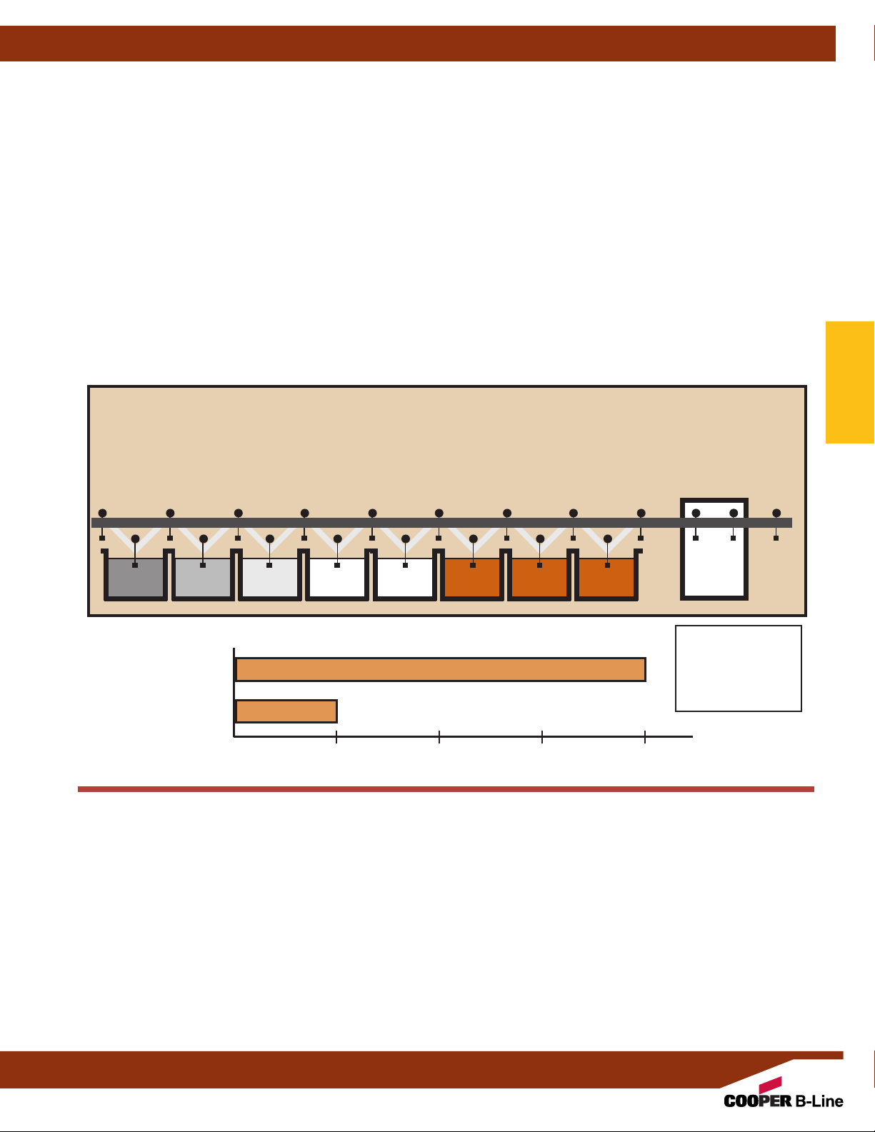
DURA-COPPER™ & DURA-GREEN™EPOXY COATING PROCESS
TANK 1
Parts are thoroughly cleaned
and phosphatized.
TANK 2
Rinse is
applied to
remove
insoluble salts
and unreacted
phosphates.
TANK 3
Phosphatized
sealer is applied
to insure
corrosion resistance and paint
adhesion.
TANK 4
The material
moves through
clear water
rinse to remove
excess phosphates.
TANK 5
Deionized rinse
prepares the
metal for the
cathodic
electro-coating.
TANK 6
The electrocoating tank
applies a
uniform coat of
epoxy paint to
the entire surface.
Quality Assurance
Cooper B-Line System's Quality
Assurance Program has been
developed and implemented for
compliance to various industry
standards and specifications.
TANK 7
The first
post rinse
removes any
unelectrically
attracted
solids.
TANK 8
The final rinse
insures a
smooth,
nonblemish
finish.
BAKE OVEN
The curing
process takes
20 minutes at a
baking
temperature of
375°F (199°C).
Technical Data
SALT SPRAY TEST RESULTS
Dura-Copper
Epoxy
Dura-Copper
out performs
Copper Plating
4 to 1
Copper Plating
Elapsed Time
(1) All salt spray (fog) tests conducted in accordance with ASTM B 117-73 and evaluated and rated
according to ASTM D 1654-79 Tables 1 & 2. Tests were performed and certified by an independent testing laboratory.
General Information
Torque
The torque values in this catalog are to be used as a guide only. The relationship between the applied torque or
torque wrench reading and the actual tension created in the bolt may be substantially different. Important factors
affecting torque-tension relationships include friction under the bolt head or nut, hole tolerances, and torque
wrench tolerances.
Charts and Tables
Charts and tables in this section are compiled from information published by nationally recognized organizations
and are intended for use as a guide only
the validity of such information as applied to their own applications.
Cooper B-Line, Inc. reserves the right to make specification changes without notice.
Accuracy of many commercial torque wrenches may vary as much as plus or minus 25%.
. Cooper B-Line recommends that users of this information determine
19
Page 22

Technical Data
SECTION 15140 - PIPE HANGERS AND SUPPORTS
Part I - GENERAL
1.01 SECTION INCLUDES
A. The work covered under this section consists of the furnishing of all necessary labor,
supervision, materials, equipment, and services to completely execute the pipe hanger and
supports as described in this specification.
1.02 REFERENCES
A. ASTM B 633 - Specification for Electrodeposited Coatings of Zinc on Iron and Steel.
B. ASTM A 123 - Specification for Zinc (Hot-Dip Galvanized) Coatings on Iron and Steel Products.
Technical Data
C. ASTM A 653 - Specification for Steel Sheet, Zinc-Coated (Galvanized) or Zinc-Iron
Alloy-Coated (Galvannealed) by the Hot-Dip Process.
D. ASTM A 1011 - Specification for Steel, Sheet and Strip, Hot-Rolled, Carbon, Structural,
High-Strength Low-Alloy, and High-Strength Low-Alloy with Improved Formability.
E. ANSI/MSS SP-58 - Manufacturers Standardization Society: Pipe Hangers and Supports -
Materials, Design, and Manufacture.
F. ANSI/MSS SP-69 - Manufacturers Standardization Society: Pipe Hangers and Supports -
Selection and Application.
G. NFPA 13 - Installation of Sprinkler Systems.
1.03 QUALITY ASSURANCE
A. Hangers and supports used in fire protection piping systems shall be listed and labeled by
Underwriters Laboratories.
B. Steel pipe hangers and supports shall have the manufacturers name, part number, and
applicable size stamped in the part itself for identification.
C. Hangers and supports shall be designed and manufactured in conformance with MSS SP-58.
D. Supports for sprinkler piping shall be in conformance with NFPA 13.
1.04 SUBMITTALS
A. Submit product data on all hanger and support devices, including shields and attachment
methods. Product data to include, but not limited to materials, finishes, approvals, load
ratings, and dimensional information.
Part II - PRODUCTS
2.01 ACCEPTABLE MANUFACTURERS
A. Manufacturer: Subject to compliance with these specifications, pipe hanger and support
systems shall be as manufactured by Cooper B-Line, Inc.
2.02 PIPE HANGERS AND SUPPORTS
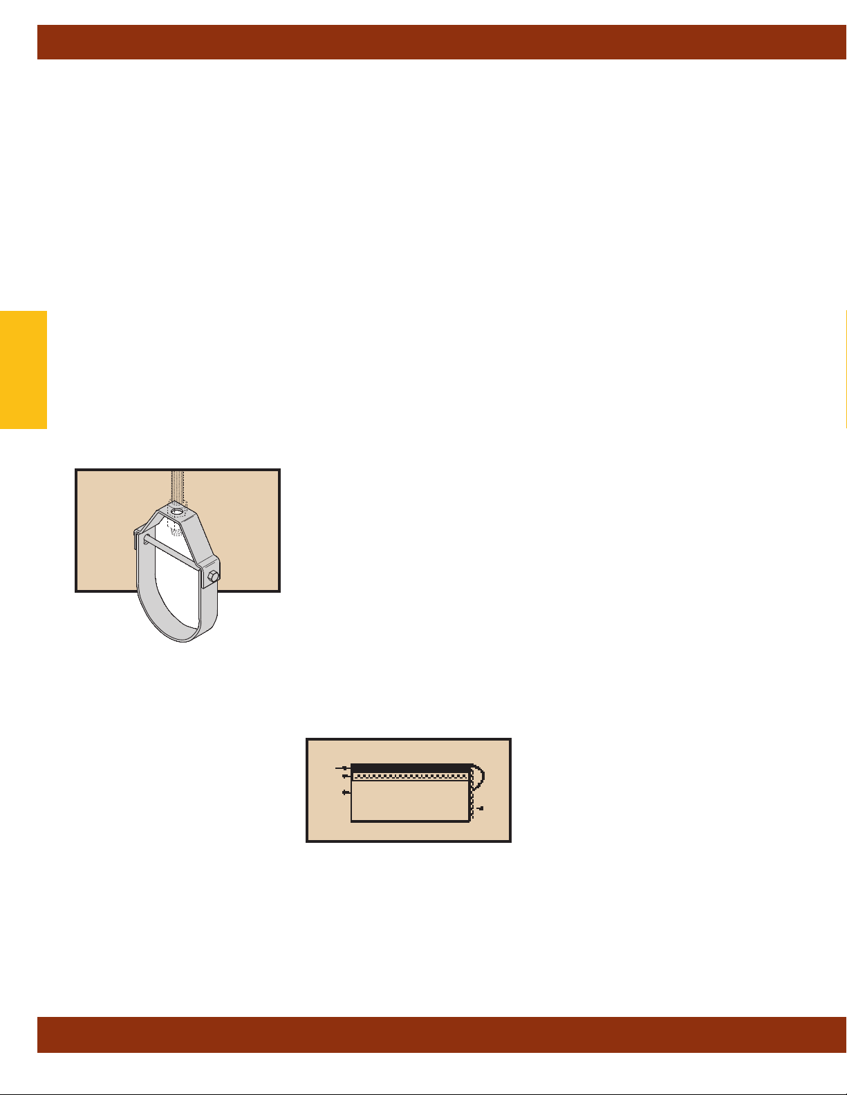
A. Hangers
1. Uninsulated pipes 2 inch and smaller:
a. Adjustable steel swivel ring (band type) hanger, Cooper B-Line B3170, Fig. 200.
b. Adjustable steel swivel J-hanger, Cooper B-Line B3690.
c. Malleable iron ring hanger, Cooper B-Line B3198R or hinged ring hanger,
B3198H.
d. Adjustable steel clevis hanger, Cooper B-Line B3104, B3100 or 1U.
20
Page 23

Technical Data
2. Uninsulated pipes 21/2 inch and larger:
a. Adjustable steel clevis hanger, Cooper B-Line B3100.
b. Pipe roll with sockets, Cooper B-Line B3114.
c. Adjustable steel yoke pipe roll, Cooper B-Line B3110.
3. Insulated pipe - Hot or steam piping:
a. 2 inch and smaller pipes: use adjustable steel clevis with galvanized sheet metal
shield, Cooper B-Line B3100 with B3151 or B3153 series.
1
b. 2
/2 inch and larger pipes:
i. Adjustable steel yoke pipe roll with pipe covering protection saddle, Cooper
B-Line B3110 with B3160 - B3165 series.
ii. Pipe roll with sockets with pipe covering protection saddle, Cooper B-Line
B3114 with B3160 - B3165 series.
4. Insulated pipe - Cold or chilled water piping:
a. 5 inch and smaller pipes: use adjustable steel clevis with galvanized sheet metal
shield, Cooper B-Line B3100 with B3151 or B3153 series.
b. 6 inch and larger pipes:
i. Adjustable steel yoke pipe, Cooper B-Line B3110, with B3380CW - B3384CW
calcium silicate shield.
ii. Pipe roll with sockets, Cooper B-Line B3114, with B3380CW - B3384CW calcium
silicate shield.
Technical Data
B. PIPE CLAMPS
1. When flexibility in the hanger assembly is required due to horizontal movement, use
pipe clamps with weldless eye nuts, Cooper B-Line B3140 or B3142 with B3200. For
insulated lines use double bolted pipe clamps, Cooper B-Line B3144 or B3146 with B3200.
C. MULTIPLE OR TRAPEZE HANGERS
1. Trapeze hangers shall be constructed from 12 gauge roll formed ASTM A 1011 SS Gr. 33
structural steel channel, 1
required.
2. Mount pipes to trapeze with two piece pipe straps sized for outside diameter of pipe,
Cooper B-Line B2000 series.
3. For pipes subjected to axial movement:
a. Strut mounted roller support, Cooper B-Line B3126. Use pipe protection shield or
saddles on insulated lines.
b. Strut mounted pipe guide, Cooper B-Line B2417.
D. WALL SUPPORTS
1. Pipes 4 inch and smaller:
a. Carbon steel hook, Cooper B-Line B3191.
b. Carbon steel J-hanger, Cooper B-Line B3690.
2. Pipes larger than 4 inch:
a. Welded strut bracket and pipe straps, Cooper B-Line B3064 and B2000 series.
b. Welded steel brackets, Cooper B-Line B3066 or B3067, with roller chair or adjustable
steel yoke pipe roll. Cooper B-Line B3120 or B3110. Use pipe protection shield or
saddles on insulated lines.
5
/8” x 15/8” minimum, Cooper B-Line B22 strut or stronger as
21
Page 24

Technical Data
E. FLOOR SUPPORTS
1. Hot piping under 6 inch and all cold piping:
a. Carbon steel adjustable pipe saddle and nipple attached to steel base stand sized
for pipe elevation, Cooper B-Line B3093 and B3088T or B3090 and B3088. Pipe saddle
shall be screwed or welded to appropriate base stand.
2. Hot piping 6 inch and larger:
a. (Adjustable) Roller stand with base plate, Cooper B-Line B3117SL (or B3118SL).
b. Adjustable roller support and steel support sized for elevation, Cooper B-Line B3124
F. VERTICAL SUPPORTS
1. Steel riser clamp sized to fit outside diameter of pipe, Cooper B-Line B3373.
Technical Data
G. COPPER TUBING SUPPORTS
1. Hangers shall be sized to fit copper tubing outside diameters.
a. Adjustable steel swivel ring (band type) hanger, Cooper B-Line B3170CT.
b. Malleable iron ring hanger, Cooper B-Line B3198CT or hinged ring hanger B3198HCT.
c. Adjustable steel clevis hanger, Cooper B-Line B3104CT.
H. PLASTIC PIPE SUPPORTS
1. V-bottom clevis hanger with galvanized 18 gauge continuous support channel, Cooper
B-Line B3106 and B3106V, to form a continuous support system for plastic pipe or flexible
tubing.
I. SUPPLEMENTARY STRUCTURAL SUPPORTS
1. Design and fabricate supports using structural quality steel bolted framing materials
as manufactured by Cooper B-Line. Channels shall be roll formed, 12 gauge ASTM
A 1011 SS Grade 33 steel, 1
Submit designs for pipe tunnels, pipe galleries, etc., to engineer for approval. Use
clamps and fittings designed for use with the strut system.
5
/8” x 15/8” or greater as required by loading conditions.
2.04 UPPER ATTACHMENTS
A. BEAM CLAMPS
1. Beam clamps shall be used where piping is to be suspended from building steel.
Clamp type shall be selected on the basis of load to be supported, and load configuration.
2. C-Clamps shall have locknuts and cup point set screws, Cooper B-Line B351L, B3036L or Fig. 65XT
Top flange C-clamps shall be used when attaching a hanger rod to the top flange of
structural shapes, Cooper B-Line B3034 or B3033. Refer to manufacturers’
recommendation for setscrew torque. Retaining straps shall be used to maintain the
clamp’s position on the beam where required (Fig. 69, Fig. 69R).
3. Center loaded beam clamps shall be used where specified. Steel clamps shall be Cooper
B-Line B3050 or B3055. Malleable iron or forged steel beam clamps with cross bolt shall
be Cooper B-Line B3054 or B3291 - B3297 series as required to fit beams.
B. CONCRETE INSERTS
1. Cast in place spot concrete inserts shall be used where applicable, either steel or
malleable iron body, Cooper B-Line B2500 or B3014. Spot inserts shall allow for lateral
adjustment and have means for attachment to forms. Select insert nuts to suit
threaded hanger rod sizes, Cooper B-Line N2500 or B3014N series.
22
Page 25

Technical Data
2. Continuous concrete inserts shall be used where applicable. Channels shall be 12
gauge, ASTM A 1011 SS Grade 33 structural quality carbon steel, complete with
styrofoam inserts and end caps with nail holes for attachment to forms. The
continuous concrete insert shall have a load rating of 2,000 lbs/ft. in concrete,
Cooper B-Line B22I, B32I, or B52I (B52I is limited to 1,500 lbs/ft.). Select channel nuts
suitable for strut and rod sizes.
2.05 VIBRATION ISOLATION AND SUPPORTS
A. For refrigeration, air conditioning, hydraulic, pneumatic, and other vibrating system
applications, use a clamp that has a vibration dampening insert and a nylon inserted
locknut. For copper and steel tubing use Cooper B-Line BVT series VibraClamps, for pipe
sizes use BVP series.
B. For larger tubing or piping subjected to vibration, use neoprene or spring hangers
as required.
C. For base mounted equipment use vibration pads, molded neoprene mounts, or spring
mounts as required.
D. Vibration isolation products as manufactured by Cooper B-Line, VibraTrol systems.
Technical Data
2.06 ACCESSORIES
A. Hanger rods shall be threaded both ends, Cooper B-Line B3205, or continuous threaded rods
of circular cross section. Use adjusting locknuts at upper attachments and hangers.
No wire, chain, or perforated straps are allowed.
B. Shields shall be 180° galvanized sheet metal, 12 inch minimum length, 18 gauge minimum
thickness, designed to match outside diameter of the insulated pipe, Cooper B-Line B3151.
1
C. Pipe protection saddles shall be formed from carbon steel,
sized for insulation thickness. Saddles for pipe sizes greater than 12 inch shall have a
center support rib.
/8 inch minimum thickness,
2.07 FINISHES
INDOOR FINISHES
A. Hangers and clamps for support of bare copper piping shall be coated with copper colored
epoxy paint, Cooper B-Line Dura-Copper. Additionally a plastic coating or a felt lining in
hanger can be used.
B. Hangers for other than bare copper pipe shall be zinc plated in accordance with ASTM
B 633 - SC3 or shall have an electro-deposited green epoxy finish, Cooper B-Line Dura-Green.
C. Strut channels shall be pre-galvanized in accordance with ASTM A 653 G90 or have
an electro-deposited green epoxy finish, Cooper B-Line Dura-Green.
OUTDOOR AND CORROSIVE AREA FINISHES
D. Hangers and strut located outdoors shall be hot dip galvanized after fabrication in
accordance with ASTM A 123. All hanger hardware shall be hot-dip galvanized or
stainless steel. Zinc plated hardware is not acceptable for outdoor or corrosive use.
E. Hangers and strut located in corrosive areas shall be Type 304 (316) stainless steel
with stainless steel hardware.
23
Page 26

Technical Data
Part III - EXECUTION
3.01 PIPE HANGERS AND SUPPORTS
A. Pipe shall be adequately supported by pipe hanger and supports specified in PART II -
PRODUCTS. Hangers for insulated pipes shall be sized to accommodate insulation
thickness.
B. Horizontal steel piping shall be supported in accordance with ANSI/MSS SP-69 & SP-58
Tables 3 and 4, excerpts of which follow below:
NOMINAL PIPE SIZE ROD DIAMETER MAXIMUM SPACING
Technical Data
3
/8” - 11/4”
1
/2”
1
2”
1
/2”
2
3”
1
/2”
3
4”
5”
6”
8”
10”
12”
3
/8” 7’-0”
3
/8” 9’-0”
3
/8” 10’-0”
1
/2” 11’-0”
1
/2” 12’-0”
1
/2” 13’-0”
5
/8” 14’-0”
5
/8” 16’-0”
3
/4” 17’-0”
3
/4” 19’-0”
7
/8” 22’-0”
7
/8” 23’-0”
14” 1” 25’-0”
16” 1” 27’-0”
C. Horizontal copper tubing shall be supported in accordance with ANSI/MSS SP-69 & SP-58
Tables 3 and 4, excerpts of which follow below:
NOMINAL TUBING SIZE ROD DIAMETER MAXIMUM SPACING
1
/4” - 3/4”
1”
1
/4”
1
1
/2”
1
2”
1
/2”
2
3”
1
/2”
3
4”
5”
6”
8”
3
/8” 5’-0”
3
/8” 6’-0”
3
/8” 7’-0”
3
/8” 8’-0”
3
/8” 8’-0”
1
/2” 9’-0”
1
/2” 10’-0”
1
/2” 11’-0”
1
/2” 12’-0”
1
/2” 13’-0”
5
/8” 14’-0”
3
/4” 16’-0”
D. Provide means of preventing dissimilar metal contact such as plastic coated hangers,
copper colored Cooper B-Line Dura-Copper epoxy paint, or non-adhesive isolation tape
(Cooper B-Line Iso-Pipe). Galvanized felt isolators sized for copper tubing may also be used,
Cooper B-Line B3195CT.
24
Page 27

Technical Data
E. Support horizontal cast iron pipe adjacent to each hub, with 10 feet maximum spacing
between hangers.
1
F. Install hangers to provide a minimum of
adjacent work.
G. Place a hanger within 12 inches of each horizontal elbow.
H. Support vertical piping independently of connected horizontal piping. Support vertical
pipes at every (other) floor. Wherever possible, locate riser clamps directly below pipe
couplings or shear lugs.
I. Where several pipes can be installed in parallel and at the same elevation, provide trapeze
hangers as specified in Section 2.02 C. Trapeze hangers shall be spaced according to the
smallest pipe size, or install intermediate supports according to schedule in Section 3.01 B.
J. Do not support piping from other pipes, ductwork or other equipment which is not
building structure.
3.02 CONCRETE INSERTS
A. Provide inserts for placement in formwork before concrete is poured.
/2 inch space between finished covering and
Technical Data
B. Provide inserts for suspending hangers from reinforced concrete slabs and sides of
reinforced concrete beams.
C. Where concrete slabs form finished ceilings, provide inserts to be flush with slab surface.
D. For inserts carrying 5” nominal pipe and larger, provide hooked rod to concrete
reinforcement.
25
Page 28

Beam Clamps
Beam Clamps
Beam clamps offered in this section are designed to provide attachment of hanger rods to structural members without
drilling or welding. A wide range of types and sizes are available for various applications.
Materials
Carbon Steel, Malleable Iron and Forged Steel are used in the manufacturing of beam clamps and accessories. Stainless
steel and other materials are available.
Finishes
The standard finishes for mechanical supports are plain steel (oil coated) sometimes referred to as black and ElectroGalvanized Zinc (ASTM B 633 SC3). Hot-Dip Galvanized After Fabrication (ASTM A 123), Red Primer, Plastic Coating and
DURA-GREEN
™
. Other special coatings are available upon request.
Note: Due to the design of some products, (threads, connecting hardware, swivels, etc.) items may
or may not be uniformly coated with special finishes. In some cases, the hanger itself may be coated, however, the
hardware may be supplied Electro-Plated, copper plated, or in stainless steel.
Recommended Set screw Torque
1
/4”-20
4 ft/lbs
(5 Nm)
5 ft/lbs
(unless otherwise specified)
3
/8”-16
(7 Nm)
11 ft/lbs
1
/2”-13
(15 Nm)
5
/8”-11
21 ft/lbs
(28 Nm)
3
/4”-10
34 ft/lbs
(46 Nm)
Over torqued set screws will damage beam clamps in this section.
We are aware that torque wrenches are not used or not available in many instances. In the absence of a torque wrench, the
set screw should be finger tightened to the I-beam and then an additional
1
/4 to 1/2 turn applied to the set screw.
Approvals (as noted)
Items in this section are Underwriters Laboratories Listed, Factory Mutual Approved, and comply with Federal Specification
WW-H-171E & A-A-1192A or Manufacturers Standardization Society ANSI/MSS SP-69 & SP-58.
All dimensions in charts and on drawings are in inches. Dimensions shown in parentheses are in millimeters unless otherwise specified.
26
Page 29
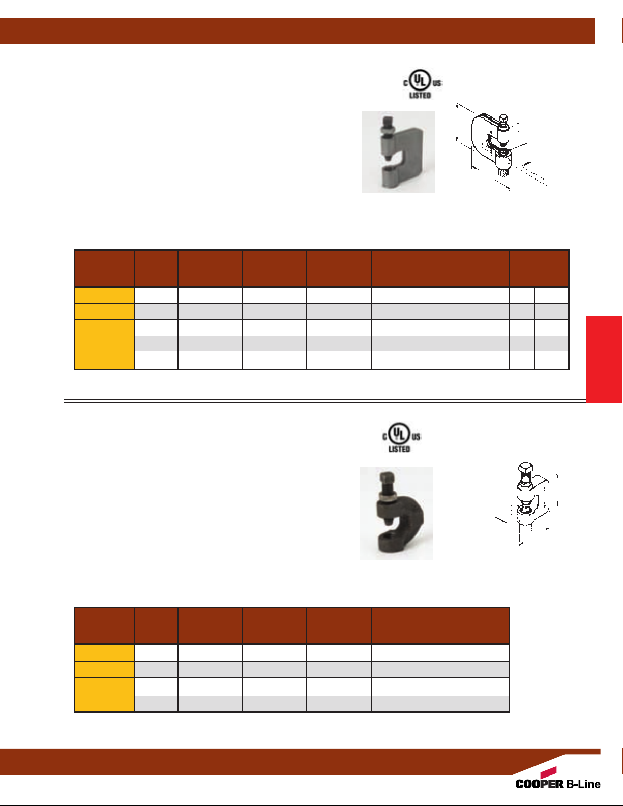
Fig. B351L - Steel C-Clamp With Locknut (TOLCO Fig. 64)
Size Range:3/8"-16 thru 7/8"-9 rod
Material: Steel
Function: For attachment to I-beams, channels, and wide flange beams
where the thickness does not exceed
secures “C” Clamp to beam.
3
Approvals: B351L (
/8”-16 - 3/4”-10), is Underwriters Laboratories Listed.
Conforms to Federal Specification WW-H-171E & A-A-1192A, Type 23 and
Manufacturers Standardization Society ANSI/MSS SP-69 & SP-58, Type 23.
Finish: Plain. Contact Cooper B-Line for alternative finishes and materials.
Note: When retaining strap is required, order B3362 thru B3365 separately.
See page 28.
Order By: Figure number and finish
Part Rod Design Maximum Iron
No. Size B C D Load Pipe Size Per UL
A in. (mm) in. (mm) in. (mm) Lbs. (kN) in. (mm) Lbs. (kg)
B351L-3/8
B351L-1/2
B351L-5/8
B351L-3/4
B351L-7/8
3
/8"-16 23/8" (60.3) 23/8" (60.3)3/4" (19.0) 300 (0.89) 4" (100) 41 (18.6)
1
/2"-13 23/8" (60.3) 23/8" (60.3)3/4" (19.0) 380 (1.69) 6" (150) 41 (18.6)
5
/8"-11 23/8" (60.3) 21/4" (57.1)3/4" (19.0) 550 (2.44) 6" (150) 60 (27.2)
3
/4"-10 23/8" (60.3) 21/4" (57.1)3/4" (19.0) 630 (2.80) 6" (150) 71 (32.2)
7
/8"-9 3" (76.2) 31/4" (82.5) 1" (25.4) 1200 (5.34) -- -- 184 (83.4)
3
/4" (19.0mm). Hardened set screw
Beam Clamps
Set Screw and
D
B
C
Locknut Included
A
(Rod Size)
Hanger Rod
Not Included
Approx. Wt./100
Note: See page 26 for recommended setscrew torque.
Fig. B3036L - Malleable Iron C-Clamp With Locknut
3
Size Range:
Material: Malleable Iron
Function: Designed for attaching a hanger rod to the flange of a beam.
Approvals: B3036L is Underwriters Laboratories Listed. Complies
with Federal Specification WW-H-171E & A-A-1192A
Manufacturers Standardization Society ANSI/MSS SP-69 & SP-58 Type 23.
Finish: Plain or Electro-Galvanized
Order By: Figure number and finish. When retaining strap is
required, order B3362 thru B3365 separately
B3036L-3/8
B3036L-1/2
B3036L-5/8
B3036L-3/4
Note: See page 26 for recommended setscrew torque.
/8"-16 thru 3/4"-10 rod
Type 23 and
. See page 28.
Part Rod Design
No. Size B C Load
A
3
/8"-16 13/4" (44.4) 13/4" (44.4) 300 (0.89) 4" (100) 41 (18.6)
1
/2"-13 13/4" (44.4) 13/4" (44.4) 380 (1.69) 5" (125) 41 (18.6)
5
/8"-11 2" (50.8) 17/8" (47.6) 530 (2.36) 6" (150) 60 (27.2)
3
/4"-10 2" (50.8) 2" (50.8) 530 (2.36) 6" (150) 71 (32.2)
in. (mm) in. (mm) Lbs. (kN) in. (mm) Lbs. (kg)
Maximum Iron
Pipe Size Per UL
Set Screw and
Locknut Included
A
(Rod Size)
Hanger Rod
Not Included
Approx. Wt./100
Beam Clamps
3
/4"
(19.0)
B
C
All dimensions in charts and on drawings are in inches. Dimensions shown in parentheses are in millimeters unless otherwise specified.
27
Page 30
Beam Clamps
Fig. B3362, B3363, B3364, B3365 - Retaining Strap
Size Range: 6” (152.4mm) to 12” (304.8mm)
lengths
Material: Steel (Stainless Steel available)
Finish: Pre-Galvanized
Function: Designed for use with B351L
and B3036L
C-Clamps.
Order By: Figure number, length 'L', (add
1"
(25.4) minimum to flange width), and
finish.
Note: Requires field forming on beam.
Part For Use With A B 6"
No. in. (mm) in. (mm) Lbs. (kg) Lbs. (kg) Lbs. (kg) Lbs. (kg)
B3362-L B351L-3/8 & 1/2
Beam Clamps
B3363-L B351L-5/8 &3/4,
B3036L-3/8 &1/2
B3364-L B3036L-5/8 & 3/4
B3365-L B351L-7/8
11/4
" (31.7)7/16" (11.1) 27 (12.2) 35 (15.9) 44 (19.9) 52 (23.6)
11/4" (31.7)
11/4
" (31.7)
11/2
" (38.1)
Flange Width Length L
in. (mm) in. (mm)
3”-5” (76-127) 6” (152.4)
5”-7” (127-178) 8” (203.2)
7”-9” (178-228) 10” (254.0)
9”-11” (228-279) 12” (304.8)
5
/8" (15.9) 26 (11.8) 35 (15.9) 43 (19.5) 52 (23.6)
11
/16" (17.4) 26 (11.8) 35 (15.9) 43 (19.5) 52 (23.6)
3
/4
" (19.0) 32 (14.5) 42 (19.0) 52 (23.6) 62 (28.1)
B
3
/4"
(19.0)
L
A
Material Thickness
12 Gauge
(2.7)
Approx. Wt./100 for Length 'L' of
(152.4) 8" (203.2) 10" (254.0) 12" (304.8)
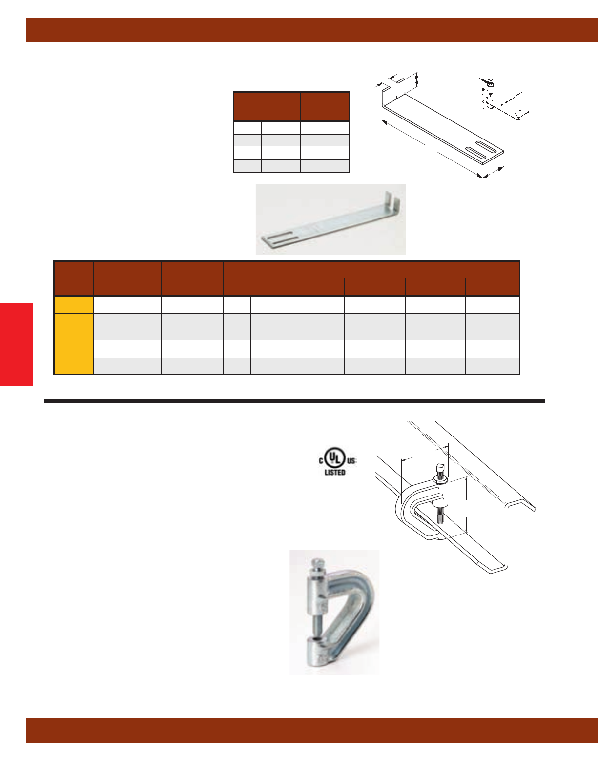
Fig. B3037 - Z-Purlin Malleable C-Clamp
Material: Malleable Iron
3
Function: Designed for attaching a
bottom flange of a Z-purlin.
Approvals: Underwriters Laboratories Listed for up to 4”
pipe. Conforms to Federal Specification WW-H-171E & A-A-1192A,
Type 23 and Manufacturers Standardization Society ANSI/MSS
SP-69 & SP-58, Type 23.
Finish: Plain or Electro-Galvanized
Order By: Figure number and finish.
Weight: Approx. Wt./100 90 Lbs.
Design Load: 400 Lbs. (1.78kN)
Note: See page 26 for recommended setscrew torque.
/8"-16 hanger rod to the
(100mm)
(40.8kg)
3"
(76.2)
Throat Opening
31
/32" (24.6)
Bottom Hanger Rod
Threads
3
/8"-16
313/32"
(86.5)
Set Screw and
Locknut Included
All dimensions in charts and on drawings are in inches. Dimensions shown in parentheses are in millimeters unless otherwise specified.
28
Page 31
Beam Clamps
Fig. B3031-3/8 - Light Duty Malleable C-Clamp
Material: Malleable Iron
3
Function: Designed for attaching a
/8"-16 hanger rod to the top or
bottom flange of a beam or bar joist when setscrew is in the down position
as shown.
Approvals: Underwriters Laboratories Listed for up to 4” pipe. Conforms to
Federal Specification WW
-H-171E & A-A-1192A, Type 19 and Manufacturers
Standardization Society ANSI/MSS SP-69 & SP-58, Type 19.
Finish: Plain or Electro-Galvanized
Order By: Figure number and finish. When retaining strap is required,
order Fig. 69 separately
Weight: Approx. Wt./100 25 Lbs.
. See Page 35.
(11.3kg)
Design Load: 350 Lbs. (1.55kN)
Note: See page 26 for recommended setscrew torque.
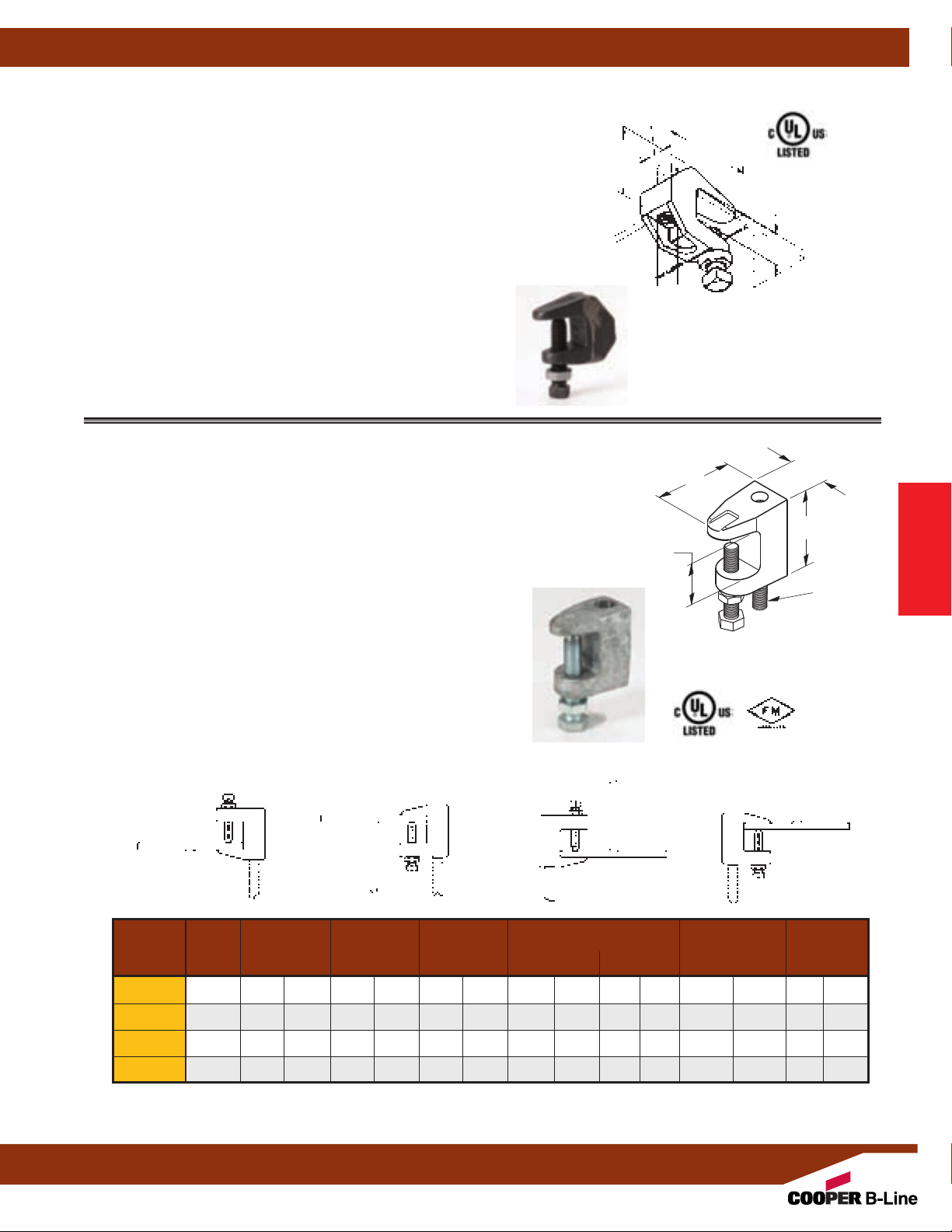
Fig. B3033 - Wide Jaw Reversible C-Clamp (TOLCO Fig. 68 & Fig. 68W)
Size Range:3/8"-16 thru 3/4"-10 rod
Material: Cast Malleable Steel with hardened cup point set screw
and jam nut
Function: For attachment to structural shapes requiring wider throat
especially under roof with bar joist construction.
This clamp may be used with the set screw in the up or down position.
Approvals: Underwriters Laboratories Listed (cULus) and Factory
3
Mutual Engineering
Approved (FM) for
/8”-16 and 1/2”-13 rod sizes.
Conforms to Federal Specification WW-H-171E Type 19 & A-A-1192A,
Type 19 & 23 and Manufacturers Standardization Society ANSI/MSS
SP-69 & SP-58, Type 19 & 23. Factory Mutual Engineering Approved
only with the setscrew in the down position.
Finish: Plain. Contact Cooper B-Line for alternative finishes and
materials.
Order By: Figure number, rod size and finish
Note: Do not over tighten set screw.
Throat Opening
1
1
/4" (31.7) for B3033-3/8 &1/2
15/16" (33.3) for B3033-5/8 & 3/4
11/2"
(38.1)
3
/4"
(19.0)
17/8"
(47.6)
Hanger Rod
Not Included
C
Set Screw and
Locknut Included
Throat Opening
11
/16" (17.5)
Set Screw and
Locknut Included
D
B
(Rod Size)
Hanger Rod
Not Included
A
Beam Clamps
Top Flange Attachment
Applications
Bottom Flange Attachment
Applications
Part Rod Design Load with Setscrew Maximum Iron Approx.
No. Size B C D Up Down Pipe Size Per UL
Wt./100
A in. (mm) in. (mm) in. (mm) Lbs. (kN) Lbs. (kN) in. (mm) Lbs. (kg)
B3033-3/83/8"-16 21/4" (57.1) 2" (50.8) 11/8" (28.6) 610 (2.71) 610 (2.71) 4" (100) 54 (24.5)
B3033-1/21/2"-13 25/16" (58.7) 23/16" (55.6) 11/4" (31.7) 750 (3.33) 1130 (5.02) 8" (200) 51 (23.1)
B3033-5/85/8"-11 25/8" (66.7) 21/2" (63.5) 13/8" (34.9) 750 (3.33) 1130 (5.02) 8" (200) 70 (31.7)
B3033-3/43/4"-10 211/16" (68.3) 21/2" (63.5) 17/16" (36.5) 750 (3.33) 1130 (5.02) 10" (250) 98 (44.4)
Note: See page 26 for recommended setscrew torque.
All dimensions in charts and on drawings are in inches. Dimensions shown in parentheses are in millimeters unless otherwise specified.
29
Page 32

Beam Clamps
Fig. B3034 - C-Clamp (TOLCO Fig. 68S)
Size Range:3/8"-16 thru 3/4"-10 rod
Material: Cast Malleable Steel with hardened cup point set
screw and jam nut
Function: Recommended for hanging from steel beam
where flange thickness does not exceed
Features: May be used on top or bottom flange of the
beam. Beveled lip allows hanging from top flange where
clearance is limited. may be installed with the set screw in
the up or down position. Of
fset design permits unlimited rod
adjustment by allowing the rod to be threaded completely
through the clamp. The rear window design permits
inspection of thread engagement.
Approvals: Underwriters Laboratories Listed and Factory
Mutual Engineering
Approved for
sizes. Conforms to Federal Specification WW-H-171E &
A-A-1192A, Type 23 and Manufacturers Standardization
Society ANSI/MSS SP-69 & SP-58, Type 19.
(cULus) Listed to support up to 4"
screw in the down position, up to 3"
1
screw in the up position.
up to 8"
(200mm) pipe with the set screw in the down position,
/2"-13 is (cULus) Listed to support
up to 6" (150mm) pipe with the set screw in the up position.
Beam Clamps
Factory Mutual Engineering Approved only with the setscrew
in the down position.
Finish: Plain. Contact Cooper B-Line for alternative finishes
and materials.
Order By: Figure number and finish
3
/4" (19.0mm).
3
/8”-16 and 1/2”-13 rod
3
/8"-16 is
(100mm) pipe with the set
(75mm) pipe with the set
Throat
Opening
3
/4" (19.0)
B3034-3/8" and B3034-1/2" sizes
Attach only as shown.
C
Set Screw and
Locknut Included
Top Flange
Attachment
Applications
D
B
(Rod Size)
Hanger Rod
Not Included
A
B3034-5/8" and B3034-3/4" sizes
Attach only as shown.
Throat
Opening
3
/4" (19.0)
Set Screw and
Locknut Included
C
D
B
A
(Rod Size)
Hanger Rod
Not Included
Bottom Flange
Attachment
Applications
Part Rod Design Load with Setscrew Maximum Iron Approx.
No. Size B C D Up Down Pipe Size Per UL
Wt./100
A in. (mm) in. (mm) in. (mm) Lbs. (kN) Lbs. (kN) in. (mm) Lbs. (kg)
B3034-3/83/8"-16 15/8" (41.3) 2" (50.8)7/8" (19.0) 610 (2.71) 610 (2.71) 4" (100) 30 (13.6)
B3034-1/21/2"-13 113/16" (46.0) 23/16" (55.6) 13/16" (30.2) 750 (3.33) 1130 (5.02) 8" (200) 47 (21.3)
B3034-5/85/8"-11 13/4" (44.5) 21/8" (54.0) 11/4" (31.7) 750 (3.33) 1130 (5.02) -- -- 58 (26.3)
B3034-3/43/4"-10 2" (50.8) 21/4" (57.2) 11/4" (31.7) 750 (3.33) 1130 (5.02) -- -- 77 (35.0)
Note: See page 26 for recommended setscrew torque.
All dimensions in charts and on drawings are in inches. Dimensions shown in parentheses are in millimeters unless otherwise specified.
30
Page 33
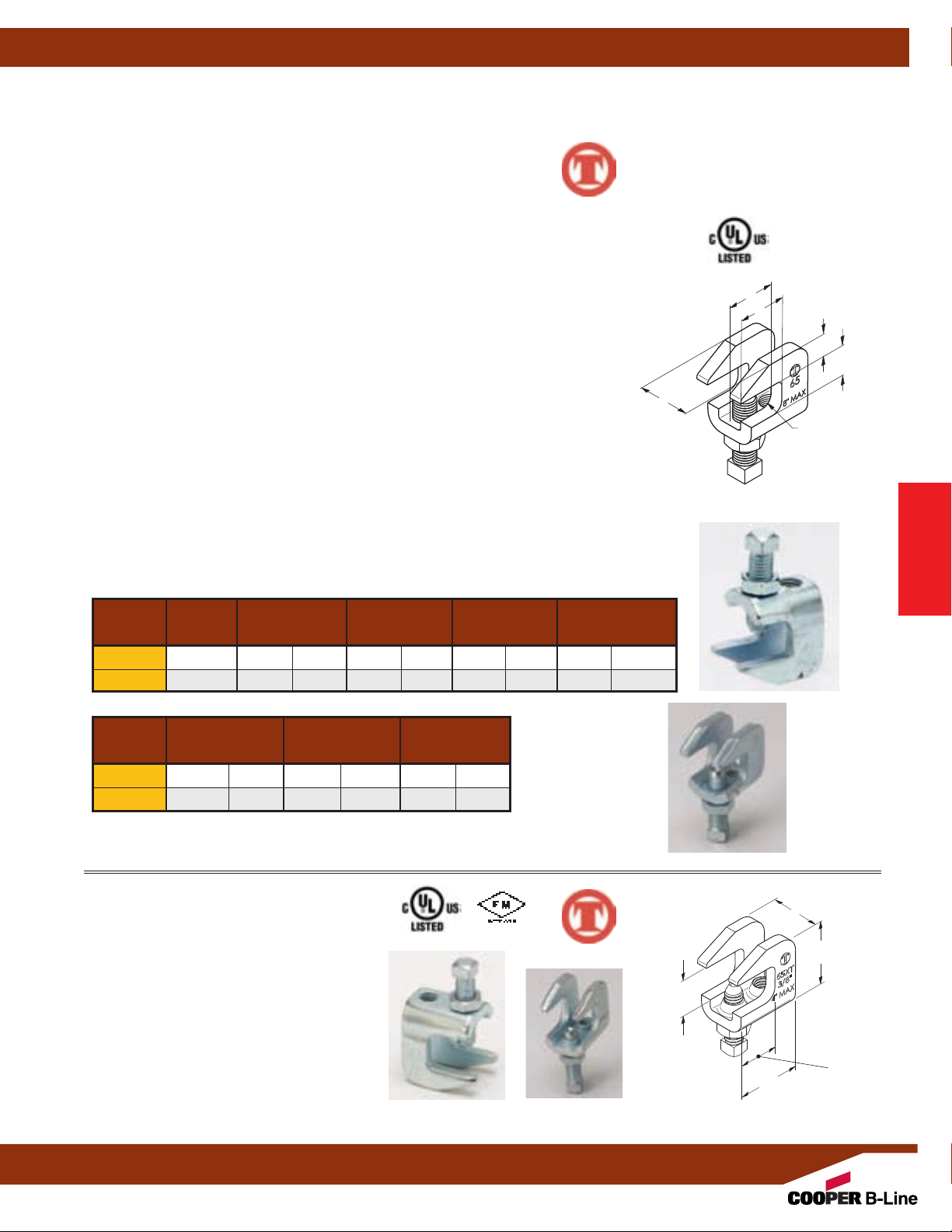
Beam Clamps
Fig. 65 - Reversible Steel C-Type Beam Clamp 3/4” (19.0mm) Throat Opening
Fig. 65XT - Reversible Steel C-Type Beam Clamp 3/4” (19.0mm) Throat Opening (bottom of page)
Size Range:
1
Fig. 65 -
Fig. 65XT -
/2"-13 rod sizes, and 5/8"-11 rod sizes
3
/8"-16 rod size (see below)
™
Material: Steel with hardened cup point set screw and jam nut
Function: Recommended for hanging from steel beam where flange thickness does
3
not exceed
/4” (19.0mm).
Features: All steel construction eliminates structural deficiencies associated with
casting type beam clamps. May be used on top or bottom flange of beam. (Beveled lip
allows hanging from top flange where clearance is limited.) May be installed with set
screw in up or down position. Of
fset design permits unlimited rod adjustment by allowing
the rod to be threaded completely through the clamp. Open design permits inspection of
thread engagement.
Approvals: Underwriters Laboratories Listed in the USA (UL) and Canada (cUL).
Exceeds requirements of the National Fire Protection Association (NFPA), pamphlet 13,
3
/8"-16 rod will support 1/2” (15mm) thru 4” (100mm) pipe
1
/2"-13 rod will support 1/2” (15mm) thru 8” (200mm) pipe
Included in the Seismic Restraints Catalog approved by the State of California
Office of Statewide Health Planning and Development (OSHPD). For additional load
spacing and placement information relating OSHPD projects, please refer to the
Seismic Restraint System Guidelines.
Finish: Plain. Contact Cooper B-Line for alternative finishes and materials.
Order By: Figure number and finish
Fig. 65 Patent #4,570,885
Component of State of
California OSHPD Approved
Seismic Restraints System
B
D
E
C
F
A
Set Screw and
Locknut Included
Beam Clamps
Part Rod Size B C D E
No. A
65-1/2
65-5/8
1
/2”-13 11/2” (38.1)
5
/8”-11 11/2” (38.1)
in. (mm) in. (mm) in. (mm) in. (mm)
3
/4” (19.0) 1” (25.4) 9/16” (14.3)
3
/4” (19.0) 1” (25.4) 9/16” (14.3)
Part F Mac Rec. Load * Approx. Wt./100
No.
65-1/2
65-5/8
in. (mm) in. (mm) in. (mm)
11/4” (31.7) 1130 (5.02) 55 (24.9)
11/4” (31.7) 1130 (5.02) 55 (24.9)
* Maximum loads for clamp with set screw in up or down position.
Fig. 65XT-3/8 - Beam Clamp
Feature: Extruded holes allow for more thread
engagement of threaded rod and set screw.
Weight: Approx. Wt./100 - 28.0 Lbs.
Design Load: 730 Lbs (3.25kN)
Finish: Plain or Electro-Galvanized
Order By: Figure number and finish
Approvals: Underwriters Laboratories Listed
and FM
Approved for uo to 4”
(100mm) pipe.
(12.7kg)
™
3
/4"
(19.0)
Set Screw and
Locknut Included
13/8"
(34.9)
1"
(25.4)
19/16"
(39.7)
7
(22.2)
/8"
All dimensions in charts and on drawings are in inches. Dimensions shown in parentheses are in millimeters unless otherwise specified.
31
Page 34
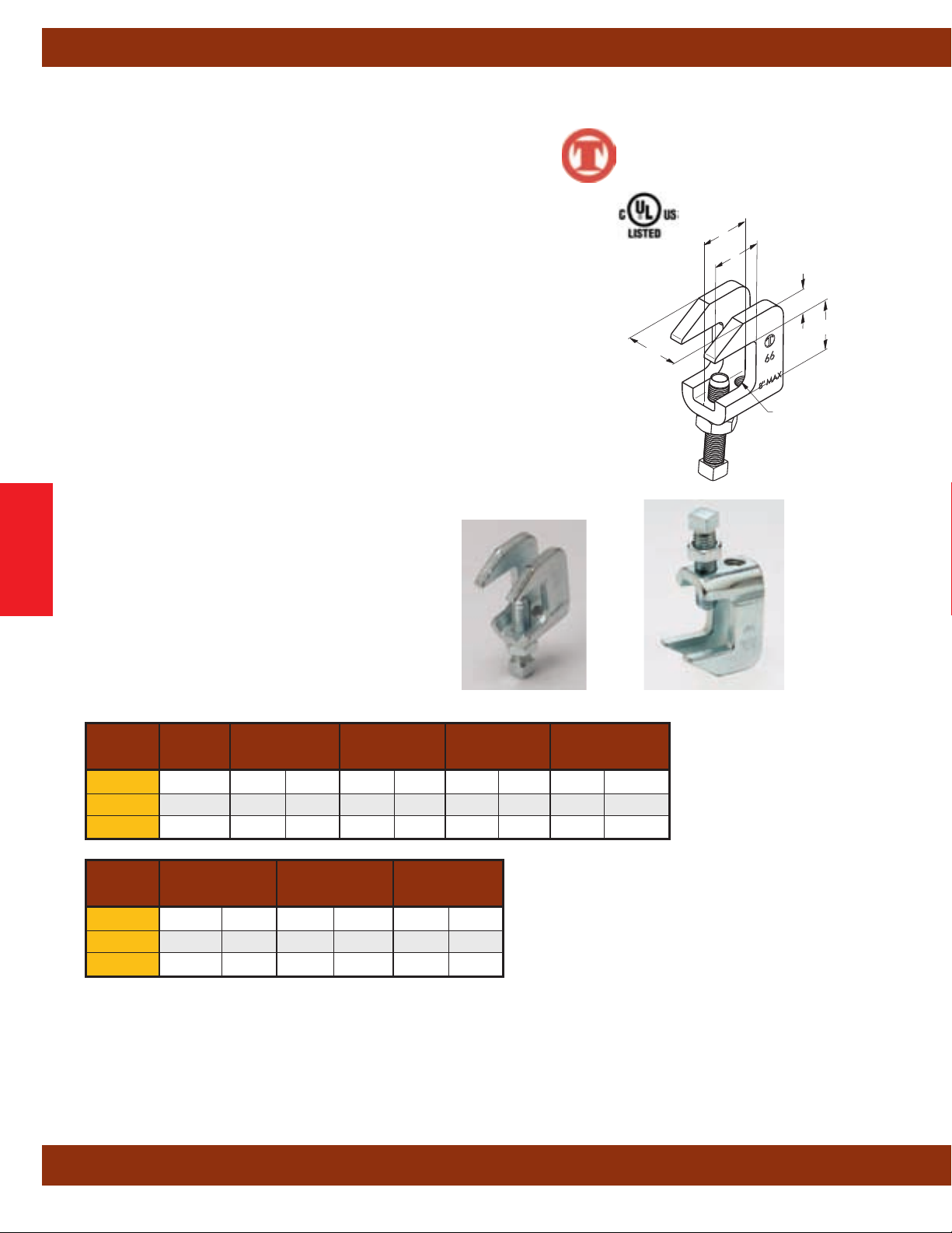
Beam Clamps
Fig. 66 - Reversible Steel C-Type Beam Clamp 11/4” (31.7mm) Throat Opening
Size Range:3/8"-16, 1/2"-13 rod sizes, and 5/8"-11 rod sizes
Material: Steel with hardened cup point set screw and jam nut
Function: Recommended for hanging from steel beam where flange
thickness does not exceed 1
Features: All steel construction eliminates structural deficiencies associated with
casting type beam clamps. May be used on top or bottom flange of beam. (Beveled lip
allows hanging from top flange where clearance is limited.) May be installed with set
screw in up or down position. Of
the rod to be threaded completely through the clamp. Open design permits inspection of
thread engagement.
Approvals: Underwriters Laboratories Listed in the USA (UL) and Canada (cUL).
Exceeds requirements of the National Fire Protection Association (NFPA), pamphlet 13,
3
/8"-16 rod will support 1/2” (15mm) thru 4” (100mm) pipe
1
/2"-13 rod will support 1/2” (15mm) thru 8” (200mm) pipe
Included in the Seismic Restraints Catalog approved by the State of California
Office of Statewide Health Planning and Development (OSHPD). For additional load
spacing and placement information relating OSHPD projects, please refer to the
Seismic Restraint System Guidelines.
Finish: Plain. Contact Cooper B-Line for alternative finishes and materials.
Order By: Figure number and finish
Beam Clamps
1
/4” (31.7mm).
fset design permits unlimited rod adjustment by allowing
Component of State of
California OSHPD Approved
Seismic Restraints System
™
B
D
E
C
F
A
Set Screw and
Locknut Included
Part Rod Size B CD E
No. A
66-3/8
66-1/2
66-5/8
3
1
5
/8”-16 13/16" (30.2) 11/4” (31.7) 1” (25.4) 7/16” (11.1)
/2”-13 11/2” (38.1) 11/4” (31.7) 1” (25.4) 9/16” (14.3)
/8”-11 11/2” (38.1) 11/4” (31.7) 1” (25.4) 9/16” (14.3)
in. (mm) in. (mm) in. (mm) in. (mm)
Part F Mac Rec. Load * Approx. Wt./100
No.
66-3/8
66-1/2
66-5/8
* Maximum loads for clamp with set screw in up or down position.
All dimensions in charts and on drawings are in inches. Dimensions shown in parentheses are in millimeters unless otherwise specified.
in. (mm) in. (mm) in. (mm)
1” (25.4) 610 (2.71) 28 (12.7)
11/4” (31.7) 1130 (5.02) 55 (24.9)
11/4” (31.7) 1130 (5.02) 55 (24.9)
32
Page 35

Beam Clamps
Fig. 67SS - Stainless Steel Reversible C-Type Beam Clamp 3/4” (19.0mm) Throat Opening
Fig. 68SS - Stainless Steel Reversible C-Type Beam Clamp Wide Mouth
Size Range:3/8"-16 and 1/2"-13 rod sizes
Material: Stainless Steel (Type 316 or 304)
Function: Recommended for hanging from steel beams where flange thickness does
3
not exceed
1
or 1
/4” (19.0mm) for Fig. 67SS
/4” (31.7mm) for Fig. 68SS.
Features: All steel construction eliminates structural deficiencies associated with
casting type beam clamps. May be used on top or bottom flange of beam. May be
installed with set screw in up or down position. Offset design permits unlimited rod
adjustment by allowing the rod to be threaded completely through the clamp.
Approvals: Underwriters Laboratories Listed in the USA (UL) and Canada (cUL).
Conforms to Manufacturers Standardization Society ANSI/MSS SP-69 & SP-58,
T
ype 19. Meets or exceeds requirements of the National Fire Protection Association
(NFPA), pamphlet 13.
3
/8"-16 rod will support 1/2” (15mm) thru 4” (100mm) pipe
1
/2"-13 rod will support 1/2” (15mm) thru 8” (200mm) pipe
Order By: Figure number and stainless steel type.
B
D
E
G
C
F
Set Screw and
Locknut Included
Fig. 67SS
Part Rod Size Pipe Size B C D E
No. A
67SS-3/8
67SS-1/2
3
/8”-161/2" - 4” (15 - 100) 3” (76,2)
1
/2”-13 5" - 8” (125 -200) 3” (76,2)
in. (mm) in. (mm) in. (mm) in. (mm) in. (mm)
7
/8” (22.2) 1” (25.4) 15/8” (41.3)
7
/8” (22.2) 1” (25.4) 15/8” (41.3)
Part F G Test Load Approx. Wt./100
No.
67SS-3/8
67SS-1/2
in. (mm) in. (mm) in. (mm) in. (mm)
15/8” (41.3) 11/8” (28.6) 1500 (6.67) 84 (38.1)
15/8” (41.3) 11/8” (28.6) 4050 (18.01) 170 (77.1)
Fig. 68SS
Part Rod Size Pipe Size B C D E
No. A
68SS-3/8
68SS-1/2
3
/8”-161/2" - 4” (15 - 100) 21/16” (52.4) 11/8” (28.6)
1
/2”-13 5" - 8” (125 -200) 21/4” (57.1) 11/4” (31.7)
in. (mm) in. (mm) in. (mm) in. (mm) in. (mm)
3
/4” (19.0) 11/4” (31.7)
13
/16” (20.6) 11/4” (31.7)
A
Beam Clamps
Part F Test Load Approx. Wt./100
No.
68SS-3/8
68SS-1/2
in. (mm) in. (mm) in. (mm)
2” (50.8) 1500 (6.67) 84 (38.1)
21/4” (57.1) 4050 (18.01) 170 (77.1)
All dimensions in charts and on drawings are in inches. Dimensions shown in parentheses are in millimeters unless otherwise specified.
33
Page 36
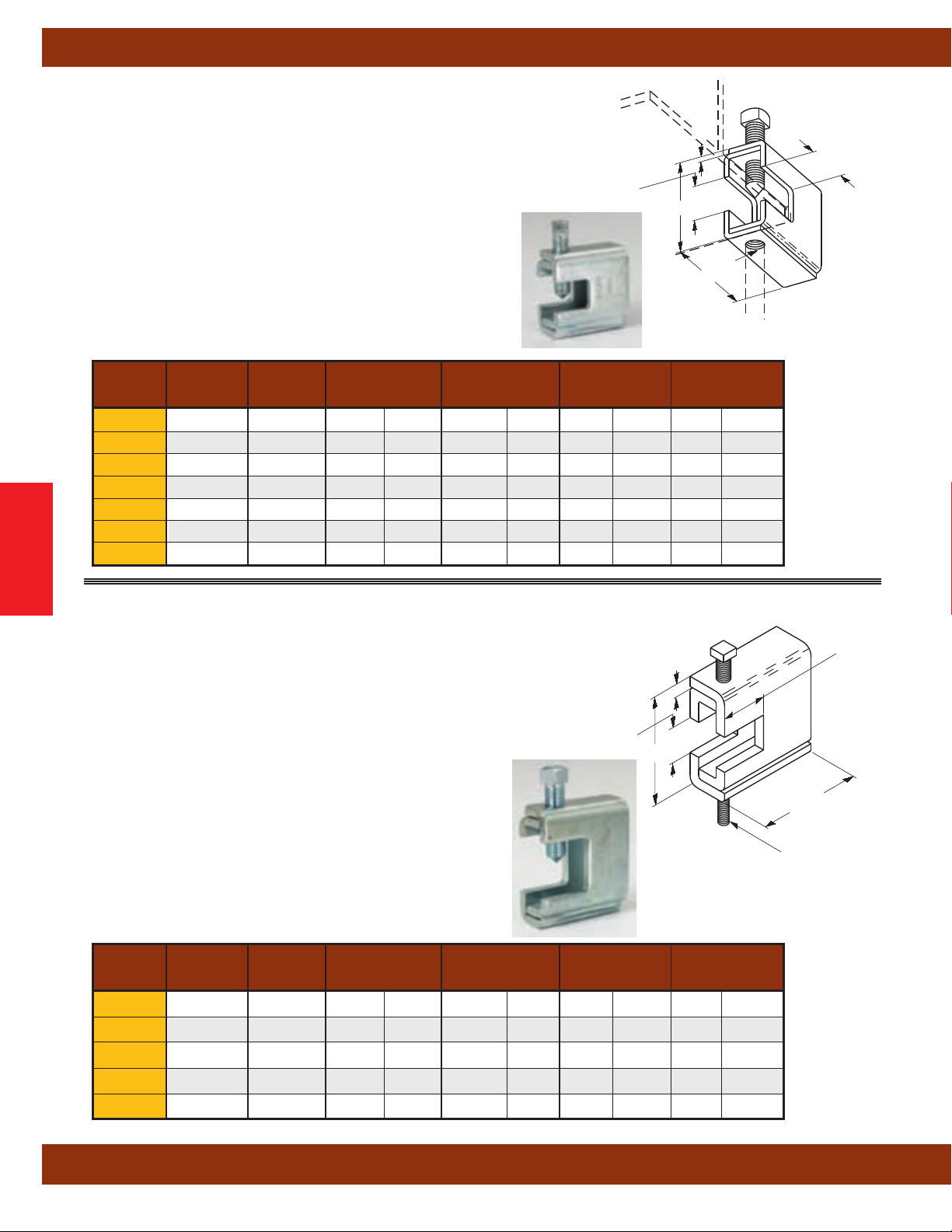
Beam Clamps
Fig. B303-B309 - Beam Clamps
Size Range:1/4"-20 thru 5/8"-11 rod
Material: Steel
Function: Designed for attaching a hanger rod to the flange of a beam.
Approvals: Conforms to Federal Specification WW-H-171E & A-A-1192A,
T
ype 19 and Manufacturers Standardization Society ANSI/MSS SP-69 &
SP-58, Type 19.
Finish: Electro-Galvanized or Hot-Dip Galvanized
Order By: Figure number and finish. When retaining strap is required,
order B312 separately. See page 37.
Recommended Set Screw Torque:
3
/8”-16 = 150 in-lbs (16.9 N•m)
1
/2”-13 = 350 in-lbs (39.5 N•m)
Part Rod Size Setscrew C T Design Load Approx. Wt./100
B303
B304
B305
B306
Beam Clamps
B307
B308
B309
No. A Size
1
/4”-20
5
/16”-18
3
/8”-16
3
/8”-16
1
/2”-13
1
/2”-13
5
/8”-11
3
/8”-16 25/16" (58.7) 11 Ga. (3.0) 400 (1.78) 72 (32.6)
3
/8”-16 25/16" (58.7) 11 Ga. (3.0) 600 (2.67) 72 (32.6)
3
/8”-16 25/16" (58.7) 11 Ga. (3.0) 600 (2.67) 72 (32.6)
1
/2”-13 27/16" (61.9) 7 Ga. (4.5) 1100 (4.89) 97 (44.0)
1
/2”-13 27/16" (61.9) 7 Ga. (4.5) 1100 (4.89) 97 (44.0)
1
/2”-13 29/16" (65.1)
1
/2”-13 29/16" (65.1)
in. (mm) in. (mm) Lbs. (kN) Lbs. (kg)
T
7
/8" (22.2)
Maximum
Flange
Thickness
1
/4" (6.3) 1500 (6.67) 133 (60.3)
1
/4" (6.3) 1500 (6.67) 133 (60.3)
C
21/2"
(63.5)
A
Set Screw
Included
1
(28.6)
1
/8"
Fig. B321 - Series Beam Clamps
Size Range:3/8"-16 thru 3/4"-10 rod
Material: Steel
Function: Designed for attaching a hanger rod to the flange of a beam.
Approvals: Conforms to Federal Specification WW-H-171E &
192A, Type 19 and Manufacturers Standardization Society
A-A-1
ANSI/MSS SP-69 & SP-58, Type 19.
Finish: Electro-Galvanized or Hot-Dip Galvanized
Ordering: Figure number and finish. When retaining strap is required,
order B312 separately
Recommended Set Screw T
1
/2”-13 = 350 in-lbs (39.5 N•m)
5
/8”-11 = 700 in-lbs (79.0 N•m)
Minimum Flange Thickness:
For B321-1 thru B321-3 =
For B321-4 & B321-5 = 5/8” (15.9)
Part Rod Size Setscrew C T Design Load Approx. Wt./100
No. A Size
B321-1
B321-2
B321-3
B321-4
B321-5
All dimensions in charts and on drawings are in inches. Dimensions shown in parentheses are in millimeters unless otherwise specified.
. See page 37.
orque:
3
/8” (9.5)
3
/8”-16
1
/2”-13
5
/8”-11
5
/8”-11
3
/4”-10
in. (mm) in. (mm) Lbs. (kN) Lbs. (kg)
1
/2”-13 39/16" (92.1)
1
/2”-13 39/16" (92.1)
1
/2”-13 39/16" (92.1)
5
/8”-11 323/32" (94.4)
5
/8”-11 323/32" (94.4)
1
/4" (6.3) 1300 (5.78) 187 (84.8)
1
/4" (6.3) 1400 (6.23) 186 (84.3)
1
/4" (6.3) 1600 (7.12) 185 (83.9)
5
/16" (7.9) 1800 (8.00) 239 (108.4)
5
/16" (7.9) 2000 (8.89) 238 (107.9)
Set Screw
Included
111/16" (42.8)
Maximum
Flange
Thickness
15/8"
T
C
(82.5)
A
(41.3)
31/4"
34
Page 37

Fig. 69 - Beam Clamp Retaining Strap (Cooper B-Line B3367)
Size Range:3/8"-16 thru 3/4"-10 rod
4” (101,6mm) thru 16” (406.4mm) lengths
Note: longer lengths are available consult factory
Material: Pre-Galvanized Steel
Function: To offer more secure fastening of various types of
beam clamps to beam where danger of movement might be
expected. NFP
all beam clamps installed in earthquake areas. Satisfies
requirements of NFPA 13.
Important Note: Good installation practice of a retaining
strap requires that the strap be held tightly and securely to all
component parts of the assembly
mechanism of some kind, such as a hex nut or the beveled
locking slot of the Fig. 69R will provide a more secure reliable
installation.
Approvals: Underwriters Laboratories Listed in the USA (UL)
and Canada (cUL). Approved for use with any listed beam
clamp. Included in the Seismic Restraints Catalog approved
by the State of California Of
and Development (OSHPD). For additional load spacing and
placement information relating OSHPD projects, please refer
to the Seismic Restraint System Guidelines.
Finish: Pre-Galvanized
Order By: Figure number, length (L), and finish.
Note: Minimum return on strap is 1”
A 13 requires the use of retaining straps with
. Therefore a locking
fice of Statewide Health Planning
(25.4mm)
Beam Clamps
Component of State of
California OSHPD Approved
Seismic Restraints System
Beam Clamps
Hole Dia. D For Use With Length
Part No.
69-3/8-L
69-1/2-L
5
/8-L
69-
3
/4-L
69-
in. (mm)
7
/16” (30.1)
9
/16” (30.1) B3033-1/2, B3034-1/2, 65-1/2, 66-1/2 Specify
11
/16” (50.8) B3033-5/8, 65-5/8, 66-5/8 Specify
13
/16” (63.5) B3033-3/4 Specify
All dimensions in charts and on drawings are in inches. Dimensions shown in parentheses are in millimeters unless otherwise specified.
B3033-3/8, B3034-3/8, B3031-3/8,
3
/8, 65XT-3/8, 66-3/8
65-
Specify
35
Page 38

Beam Clamps
Fig. 69R - Retrofit Capable Beam Clamp Retaining Strap
Size Range:3/8"-16 & 1/2"-13 rod
4” (101,6mm) thru 16” (406.4mm) lengths
Note: longer lengths are available consult factory
Material: Pre-Galvanized Steel
Function: To offer more secure fastening of various types of
beam clamps to beam where danger of movement might be
expected. NFP
all beam clamps installed in earthquake areas. Satisfies
requirements of NFPA 13.
Features: Beveled locking slot* is precisely formed to align with
the threaded section of a hanger rod or set screw and engage
the unit securely
inverted. Allows easy installation for new construction or retrofit
applications.
Important Note: Good installation practice of a retaining
strap requires that the strap be held tightly and securely to all
component parts of the assembly
mechanism of some kind, such as a hex nut or the beveled
locking slot of the Fig. 69R will provide a more secure reliable
installation.
Approvals: Underwriters Laboratories Listed in the USA (UL)
and Canada (cUL). Approved for use with any listed beam
Beam Clamps
clamp. Included in the Seismic Restraints Catalog approved
by the State of California Of
and Development (OSHPD). For additional load spacing and
placement information relating OSHPD projects, please refer
to the Seismic Restraint System Guidelines.
Finish: Pre-Galvanized
Order By: Figure number, length, and finish.
Note: Minimum return on strap is 1”
* Patent #5,947,424
A 13 requires the use of retaining straps with
. May be used as shown in Section “A-A” or
. Therefore a locking
fice of Statewide Health Planning
(25.4mm)
Component of State of
California OSHPD Approved
Seismic Restraints System
A
A
A - A
Slot Width For Use With Length
Part No.
69R-3/8-L
69R-1/2-L
All dimensions in charts and on drawings are in inches. Dimensions shown in parentheses are in millimeters unless otherwise specified.
in. (mm)
7
(30.1)
/16”
9
/16” (30.1) B3033-1/2, B3034-1/2, 65-1/2, 66-1/2 Specify
B3033-3/8, B3034-3/8, B3031-3/8,
3
/8, 65XT-3/8, 66-3/8
65-
Specify
36
Page 39

Beam Clamps
Fig. B312 - Retaining Strap
Size Range: 9” (228.6mm) to 18” (457.2mm) strap lengths
Material: Steel
Function: Designed for use with B303-B309 and B321 beam clamps.
Finish: Pre-Galvanized
Order By: Figure number and finish.
Notes:
Maximum beam thickness
For thicker beams step up one flange width size.
Requires field forming on beam.
3
/4” (19.0).
11/4"
(31.7)
Material Thickness
14 Gauge (1.9)
L
1
/4"
(6.3)
13/4"
(44.4)
1
/2"
(12.7)
Part For Flange With L Approx. Wt./100
No.
in. (mm) in. (mm) Lbs. kg
B312-6 6" (152.4) 9" (228.6) 22 (10.0)
B312-9 9" (228.6) 12" (304.8) 30 (13.6)
B312-12 12" (304.8) 15" (381.0) 40 (18.1)
B312-15 15" (381.0) 18" (457.2) 49 (22.2)
Beam Clamps
All dimensions in charts and on drawings are in inches. Dimensions shown in parentheses are in millimeters unless otherwise specified.
37
Page 40

Beam Clamps
Fig. B3050 - Beam Clamp (TOLCO Fig. 62)
Material: Steel
Function: Recommended for the suspending of hanger rod from
the center of an I-beam, equally distributing the load on both sides
of the beam. Use with B3210 eye rod, B321
or B3200 weldless rye nut.
Approvals: Conforms to Federal Specification WW-H-171E &
Type 21 and Manufacturers Standardization Society ANSI/MSS SP-69 &
SP-58, Type 21.
Finish: Plain. Contact Cooper B-Line for alternative finishes and materials.
Order By: Figure number, type, width of flange and finish.
Part No. Bolt A B C Steel Size Design Load
& Size Size
in. (mm) in. (mm) in. (mm) in. (mm) Lbs. (kN)
B3050-21/2"-13 13/8" (34.9)5/8" (15.9) 21/8" (54.0)1/4"x11/4" (6.3 x 3 1.7) 1000 (3.11)
B3050-53/4"-10 17/8" (47.6)7/8" (22.2) 3" (76.2)
Flange Width
Beam Clamps
4" (101.6)
5" (127.0)
6" (152.4)
7" (177.8)
8" (203.2)
9" (228.6)
10" (254.0)
12" (304.8)
'W' Min. Max. 2 5
Flange Thickness Approx. Wt./100 For Beam Clamp Size
in. (mm) in. (mm) lbs. (kg) lbs. (kg)
3
/16" (4.8)
5
/16" (7.9)
1
/4" (6.3)
7
/16" (11.1)
7
/16" (11.1)
9
/16" (14.3) 1" (25.4) 160 (72.6) 571 (259.0)
5
/8" (15.9) 1" (25.4) 169 (76.7) 599 (271.8)
5
/8" (15.9) 11/4" (31.7) 187 (84.8) 656 (297.6)
1 welded eye rod
A-A-1192A,
1
/2" (12.7) 116 (52.6) 429 (194.6)
5
/8" (15.9) 125 (56.7) 458 (207.8)
3
/4" (19.0) 134 (60.8) 486 (220.5)
7
/8" (22.2) 143 (64.9) 514 (233.2)
7
/8" (22.2) 152 (69.0) 543 (246.3)
Center of bolt to bottom of
Bolt and Nut Included
1
/2"x2" (12.7x 50.8) 3000 (6.67)
A
beam flange.
Bolt Size
Steel Size
A
'W'
C
B
Fig. B3040 - Adjustable Beam Clamp (TOLCO Fig. 336)
Size Range:3/8"-16 thru 3/4"-10 rod
Material: Steel
J-Hook and Hex
Nut Included
C
Center of J-Hook to bottom
of clamp body.
Function: Fits structural I-Beams and wide flange beams, flange
widths 3
1
/2" (88.9mm) to 8" (203.2mm), thickness up to 1/2" (12.7mm).
Approvals: Conforms to Federal Specification WW-H-171E &
A-A-1
192A, Type 54, and Manufacturers Standardization Society
ANSI/MSS SP-69 & SP-58, Type 27.
Finish: Plain. Contact Cooper B-Line for alternative finishes and
materials.
Order By: Figure number and finish
Part Rod Size B C Steel Size Design Load
No. A
B3040-3/8
B3040-1/2
B3040-5/8
B3040-3/4
All dimensions in charts and on drawings are in inches. Dimensions shown in parentheses are in millimeters unless otherwise specified.
3
/8"-16 23/4" (69.8) 113/16" (46.0)
1
/2"-13 23/4" (69.8) 13/4" (44.4)
5
/8"-11 3" (76.2) 13/4" (44.4)
3
/4"-10 33/8" (85.7) 17/8" (47.6)
in. (mm) in. (mm) in. (mm)
1
/4" x 11/4" (6.3 x 31.7) 300 (1.33) 120 (54.4)
1
/4" x 11/2" (6.3 x 38.1) 700 (3.11) 160 (72.6)
1
/4" x 13/4" (6.3 x 44.4) 1000 (4.45) 216 (98.0)
3
/8" x 21/2" (9.5 x 63.5) 1800 (8.00) 442 (200.5)
38
A
(Rod Size)
Hanger Rod
Not Included
C
Approx. Wt./100
Lbs. (kN) Lbs. (kg)
B
Steel Size
Page 41
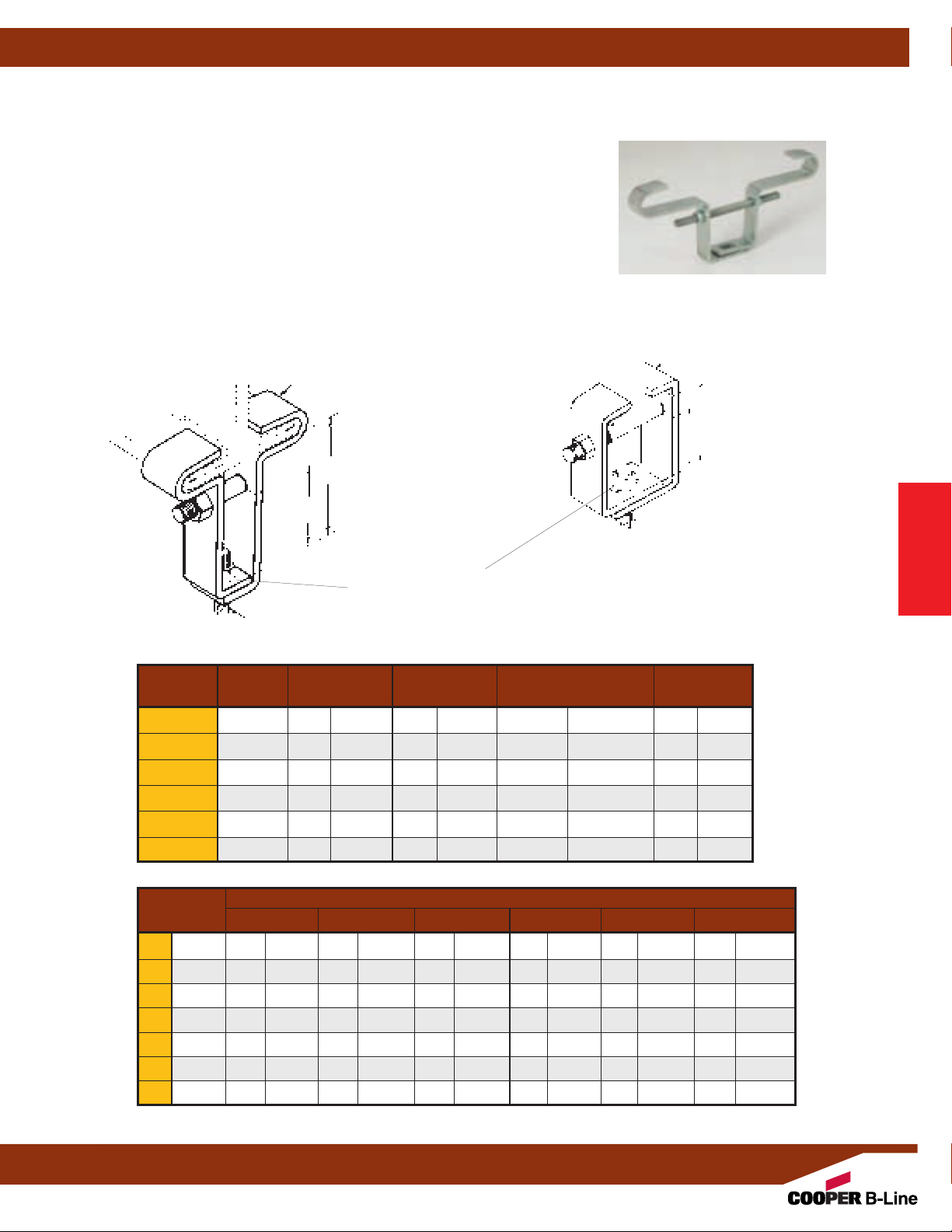
Fig. B3055 - Steel Beam Clamp
Size Range:3/8"-16 thru 1"-8 rod
Material: Steel
Function: Designed for attaching a hanger rod to be centered under beam flanges.
(50.8mm) vertical adjustment is provided in the clamp.
2"
Approvals: Conforms to Federal Specification WW-H-171E &
and Manufacturers Standardization Society ANSI/MSS SP-69 & SP-58, Type 21.
Finish: Plain or Electro-Galvanized
Order By: Figure number, flange width, and finish.
Steel Size
Bolt and Nut Included
W
C
B
A
(Rod Size)
Hanger Rod
Not Included
Center of cross bolt to
bottom of side of hanger
rod nut.
NOTE:
Slots on bottom
portions of clamp halves
(25.4) adjustment for
allow 1”
variance in flange widths
Rod Size B C Steel Size Design Load
Part No. A
B3055-3/8
B3055-1/2
B3055-5/8
B3055-3/4
B3055-7/8
3
/8"-16 3" (76.2) 4" (101.6)1/4" x 11/4" (6.3 x 31.7) 550 (2.44)
1
/2"-13 3" (76.2) 4" (101.6)1/4" x 11/2" (6.3 x 38.1) 850 (3.78)
5
/8"-11 31/4" (82.5) 41/2" (114.3)3/8" x 11/2" (9.5 x 38.1) 1100 (4.89)
3
/4"-10 31/4" (82.5) 41/2" (114.3)3/8" x 2" (9.5 x 50.8) 1500 (6.67)
7
/8"-9 31/2" (88.9) 5" (127.0)1/2" x 2" (12.7 x 50.8) 2600 (11.56)
in. (mm) in. (mm) in. (mm) Lbs. (kN)
B3055-1 1"-8 31/2" (88.9) 51/2" (139.7)1/2" x 21/2" (12.7 x 63.5) 4300 (19.12)
A-A-1192A, Type 21
B
'W'
A
(Rod Size)
Hanger Rod
Not Included
Beam Clamps
Steel Size
Note:
Box Style
C
B
Furnished For
B3055-3/8 x 2"
3
/8 x 3"
B3055B3055-3/8 x 4"
1
/2 x 2"
B3055B3055-1/2 x 3"
B3055-1/2 x 4"
5
/8 x 2"
B3055B3055-5/8 x 3"
B3055-5/8 x 4"
B3055-3/4 x 2"
3
/4 x 3"
B3055B3055-3/4 x 4"
B3055-7/8 x 3"
B3055-7/8 x 4"
7
/8 x 5"
B3055B3055-1 x 3"
B3055-1 x 4"
B3055-1 x 5"
B3055-1 x 6"
1
/8 x 4"
B3055-1
B3055-11/8 x 5"
B3055-11/8 x 6"
1
/8 x 7"
B3055-1
1
B3055-1
/4 x 4"
1
/4 x 5"
B3055-1
B3055-11/4 x 6"
1
/4 x 7"
B3055-1
Beam Clamps
Flange Width W
in. (mm)
B3055-3/8"
Approximate Wt./100 For Beam Clamp Size Lbs.
B3055-1/2"
B3055-5/8"
B3055-3/3"
(kg)
B3055-7/8"
B3055-1"
4" (101.6) 168 (76.2) 201 (91.2) 328 (148.8) 434 (196.8) 657 (298.0) 797 (361.5)
5" (127.0) 181 (82.1) 217 (98.4) 352 (159.6) 466 (211.4) 667 (302.5) 824 (373.7)
6" (152.4) 193 (87.5) 231 (104.8) 373 (169.2) 495 (224.5) 705 (319.8) 877 (397.8)
7" (177.8) 205 (93.0) 246 (111.6) 395 (179.2) 525 (238.1) 744 (337.5) 926 (420.0)
8" (203.2) 214 (97.1) 256 (116.1) 411 (186.4) 546 (247.6) 773 (350.6) 962 (436.3)
10" (254.0) 235 (106.6) 282 (127.9) 449 (203.6) 596 (270.3) 840 (381.0) 1046 (474.4)
12" (304.8) 259 (117.5) 311 (141.0) 493 (223.6) 655 (297.1) 918 (416.4) 1143 (518.4)
All dimensions in charts and on drawings are in inches. Dimensions shown in parentheses are in millimeters unless otherwise specified.
39
Page 42

Beam Clamps
Fig. B3054 - Malleable Iron Beam Clamp With Extension
Fig. B3054WO - Malleable Iron Beam Clamp Without Extension (TOLCO Fig. 329)
Size Range:3/8"-16 thru 7/8"-9 rod
Material: Malleable Iron
Function: Designed for attaching a hanger rod
to the bottom flange of a beam.
Adjustable for flange widths of
3" (76.2mm) to 7" (177.8mm) and a flange thickness of no greater
5
/8" (15.9mm).
than
Approvals: Underwriters Laboratories Listed. Conforms to
Federal Specification WW
-H-171E & A-A-1192A, Type 30 and
Manufacturers Standardization Society ANSI/MSS SP-69 &
SP-58, Type 30.
Finish: Plain or Electro-Galvanized
Ordering: Figure number and finish
Beam Clamps
B3054WO
B3054-Rod Size
Clamping Rod and Nuts
Included
E
Rod Take-Out
A
(Rod Size)
Hanger Rod Not
Included
E
Rod
Size
Part No. A 3"
(76.2) 4" (101.6) 5" (127.0) 6" (152.4) 7" (177.8)
Rod Take Out 'E' For Beam Flange Width Of
B3054-3/83/8"-16 411/16" (119.1) 49/16" (115.9) 45/8" (117.5) 4" (101.6) 31/8" (79.4)
B3054-1/21/2"-13 413/16" (122.2) 41/2" (114.3) 45/16" (109.5) 315/16" (100.0) 31/4" (82.5)
B3054-5/85/8"-11 47/8" (123.8) 45/8" (117.5) 43/8" (111.1) 33/4" (95.2) 35/16" (84.1)
B3054-3/43/4"-10 51/8" (130.2) 5" (127.0) 45/8" (117.5) 41/4" (107.9) 33/4" (95.2)
B3054-7/8
7
/8"-9 53/16" (131.8) 47/8" (123.8) 411/16" (119.1) 45/16" (109.5) 33/4" (95.2)
Design Load Max. Iron Pipe Size Per UL Approx. Wt./100
Part No.
Lbs. (kN) in. (mm) Lbs. (kg)
B3054-3/8 730 (3.25) 4” (100) 236 (107.0)
B3054-1/2 1350 (6.00) 8” (200) 254 (115.2)
B3054-5/8 1365 (6.07) 10” (250) 260 (117.9)
B3054-3/4 1365 (6.07) 10” (250) 278 (126.1)
B3054-7/8 1365 (6.07) 10” (250) 292 (132.4)
All dimensions in charts and on drawings are in inches. Dimensions shown in parentheses are in millimeters unless otherwise specified.
40
Page 43
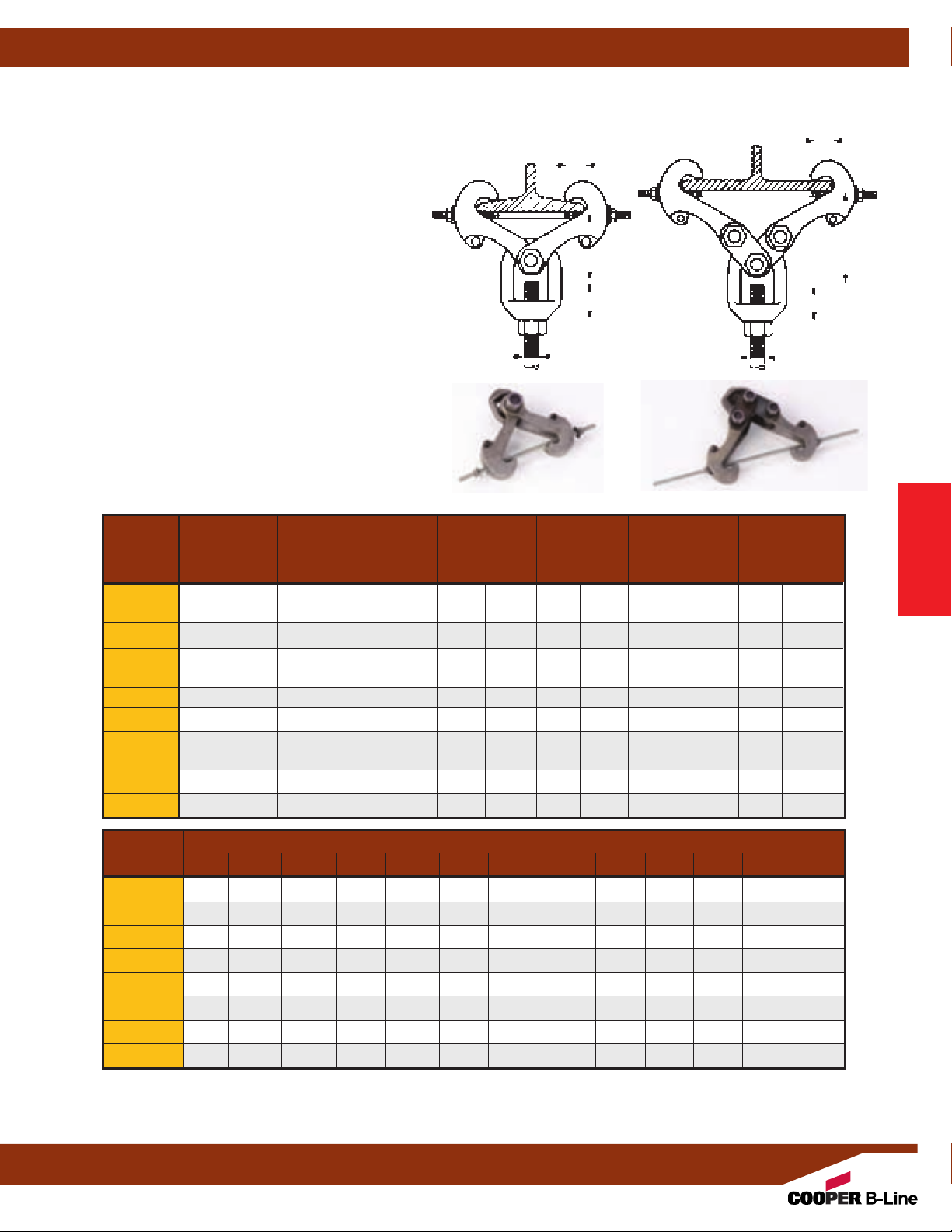
Fig. B3291, B3292, B3293, B3294, B3295, B3296, B3297, B3298
UFS Beam Clamp With Weldless Eye Nut
Available with left hand threads by adding an L to part number Example: B3291L-*
Size Range:3/8"-16 thru 2"-41/2 rod
Material: Forged Steel
Function: Designed for attaching a hanger rod to the
bottom flange of a beam.
of 3"
(76.2mm) to 15" (381.0mm). and flange thickness of
no greater than 1
1
/32" (26.2mm).
Approvals: Complies with Federal Specification
WW
-H-171E & A-A-1192A (Type 28 without links;
Type 29 with links,) and ANSI/MSS SP-58 (Type 28
without links; Type 29 with links).
Finish: Plain or Electro-Galvanized
Order By: Figure number, rod size and finish.
Note: Design load for B3291 thru B3295 based on
maximum rod size shown. Use the appropriate all
threaded rod design load shown on page 300 for sizes
less than maximum.
Adjustable from flange widths
E
B
A
Without
Links
Beam Clamps
C
C
E
B
With
Links
A
Maximum
Beam Flange Rod Size A
Part No. Thickness (Specify) B C Design Load Approx. Wt./100
*Rod Size In. (mm) * In. (mm) In. (mm) Lbs. (kN) Lbs. (kg)
3
B3291-* .60 (15.2)
B3292-* .60 (15.2)
B3293-*∆ .60 (15.2)
B3294-* 1.031
(26.2)
B3295-*∆ 1.031 (26.2)
B3296-* 1.031 (26.2) 1"-8, 11/8
B3297-*∆ 1.031
(26.2) 1
B3298-* 1.031 (26.2) 13/4
/8"-16, 1/2"-13,
5
/8"-11, 3/4"-10
7
/8
"-9, 1"-8 111/16
3
/8"-16, 1/2"-13, 5/8"-11,
3
/4
"-10, 7/8
"-9, 1"-8
7
/8
"-9, 1"-8 11/2
7
/8
"-9, 1"-8 11/2
"-7, 21/8
11/4
"-7, 11/2
1
/8
"-7, 11/4
"-6
"-7, 11/2
"-5, 2"-41/2
11/4
111/16
"-6 21/8
49/16
" (31.7) 11/8
" (42.9) 11/8
" (42.9) 11/8
" (38.1) 11/8
" (38.1) 11/8
" (54.0) 11/8
" (54.0) 11/8
" (115.9) 11/8
" (28.6) 3230 (14.36) 390 (176.9)
" (28.6) 5900 (26.24) 915 (415.0)
" (28.6) 5900 (26.24) 1300 (589.6)
" (28.6) 5900 (26.24) 2165 (982.0)
" (28.6) 5900 (26.24) 3385 (1535.4)
" (28.6) 11500 (51.15) 2390 (1084.1)
" (28.6) 11500 (51.15) 3575 (1621.6)
" (28.6) 11500 (51.15) 3675 (1666.9)
'E' Rod Take-Out For Flange Width
Part No. 3" 4" 5" 6" 7" 8" 9" 10" 11" 12" 13" 14" 15"
1
/2
B3291-* 4
"55/16
B3292-* -- 4
B3293-*∆ -- -- -- -- 5
B3294-* -- 6
B3295-* ∆ -- -- -- -- -- -- -- -- 8
B3296-* -- 7
B3297-* ∆ -- -- -- -- -- -- -- -- 8
B3298-* -- 8
* Rod Size required to finish part number (see Rod Size 'A' in top chart).
∆ These part numbers are furnished with links.
All dimensions in charts and on drawings are in inches. Dimensions shown in parentheses are in millimeters unless otherwise specified.
"41/16
3
/4
"47/16
13
/16
"65/8
3
/16
"7" 63/4
3
/8
"87/16
"35/8
"41/16
"63/8
"83/16
To determine (mm) in the above chart, multiply inches by 25.4.
"27/8
"33/8
15
"57/8
"61/4
"73/4
" -- -- -- -- -- -- -- -" -- -- -- -- -- -- -- --
/16
"6" 55/16
"57/8
"65/16
"73/4
"53/8
"513/16
"71/4
" 5" -- -- -- -- --
"413/16
"65/8
" -- -- -- -- --
1
/8
"73/4
"53/16
" -- -- -- -- --
1
/2
"81/8
" -- -- -- -- --
"71/8
"71/2
"65/8
"61/16
"7"67/16
Beam Clamps
"
"
41
Page 44
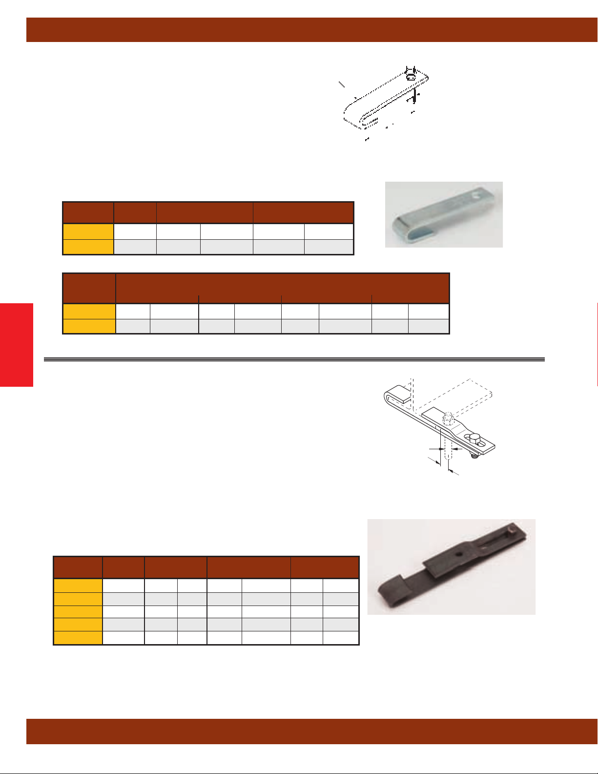
Beam Clamps
Fig. B3042 - Top Beam Hook (TOLCO Fig. 61)
Size Range:3/8"-16 and 1/2"-13 rod
Material: Steel
Function: Designed for attaching hanger rod to the top flange
of a beam or angle truss.
The support rod completes assembly
and secures it to the flange.
Finish: Plain or Electro-Galvanized
Order By: Figure number flange width, flange thickness and
finish.
For Pipe Size Design Load
Part No. A
B3042-3/8
B3042-1/2
3
/8"-16
1
/2"-13 21/2"-31/2" (65-90) 500 (2.22)
in. (mm) Lbs. (kN)
3
/4"-2" (20-50) 300 (1.33)
Approximate Wt./100 Lbs. (kg)
For Width of Beam Flange 'W'
Part No. 4" (101.6) 6" (152.4) 8" (203.2) 12" (304.8)
Beam Clamps
B3042-3/8 47 (21.3) 62 (28.1) 72 (32.6) 108 (49.0)
B3042-1/2 65 (29.5) 86 (39.0) 105 (47.6) 146 (66.2)
Steel Size
W
1
/8" (3.2) clearance between hanger rod
Allows
and flange of beam.
A
(Rod Size)
Hanger Rod
Not Included
Fig. B3045 - Side Beam Clamp (TOLCO Fig. 335)
Size Range:3/8"-16 thru 7/8"-9 rods
(76.2mm) thru 9” (228.6mm) flange widths
3”
Material: Steel
Function: Designed for attaching hanger rod to the side of a beam
flange. W
Approvals: Conforms to Federal Specification WW-H-171E &
A-A-1
ANSI/MSS SP-69 & SP-58, Type 25.
Finish: Plain or Electro-Galvanized
Order By: Figure number, flange width and thickness, and finish.
orks on top or bottom of beam.
192A, Type 53 and Manufacturers Standardization Society
Rod Size B Flange Width Design Load
Part No. A
B3045-3/8
B3045-1/2
B3045-5/8
B3045-3/4
B3045-7/8
3
1
5
5
5
/8"-16 21/16" (52.4) 3" - 9" (76.2 - 228.6) 300 (1.33)
/2"-13 25/16" (58.7) 3" - 9" (76.2 - 228.6) 500 (2.22)
/8"-11 27/16" (61.9) 3" - 9" (76.2 - 228.6) 700 (3.11)
/8"-11 27/8" (73.0) 3" - 9" (76.2 - 228.6) 800 (3.55)
/8"-11 3" (76.2) 3" - 9" (76.2 - 228.6) 1200 (5.33)
in. (mm) in. (mm) Lbs. (kN)
Bolt and Nut Included
A (Rod Size)
Hanger Rod Not Included
B
All dimensions in charts and on drawings are in inches. Dimensions shown in parentheses are in millimeters unless otherwise specified.
42
Page 45

Fig. B3042T - Bar Joist Hanger (TOLCO Fig. 61T)
Size Range:3/8"-16 and 1/2"-13 rod
Material: Steel
Function: Designed to hook on top chord of metal bar joist.
Hanger rod is threaded into product and secured with a washer
and nut.
Approvals: Underwriters Laboratories Listed in the USA (UL)
and Canada (cUL) for up to 4”
(150mm) pipe with
to 6”
Finish: Plain. Contact Cooper B-Line for alternative finishes
and materials.
Order By: Figure number and finish.
1
(100mm) pipe with
/2"-13 rod.
3
/8"-16 rod, up
Beam Clamps
Part No. Size
B3042T-3/83/8"-16 Up to 4" (up to 100) 300 (1.33) 50.6 (22.9)
B3042T-1/21/2"-13 6" (150) 600 (2.67) 50.0 (22.7)
Rod Size For Pipe Size Design Load Approx. Wt./100
in. (mm) Lbs. (kN) Lbs. (kg)
Beam Clamps
All dimensions in charts and on drawings are in inches. Dimensions shown in parentheses are in millimeters unless otherwise specified.
43
Page 46
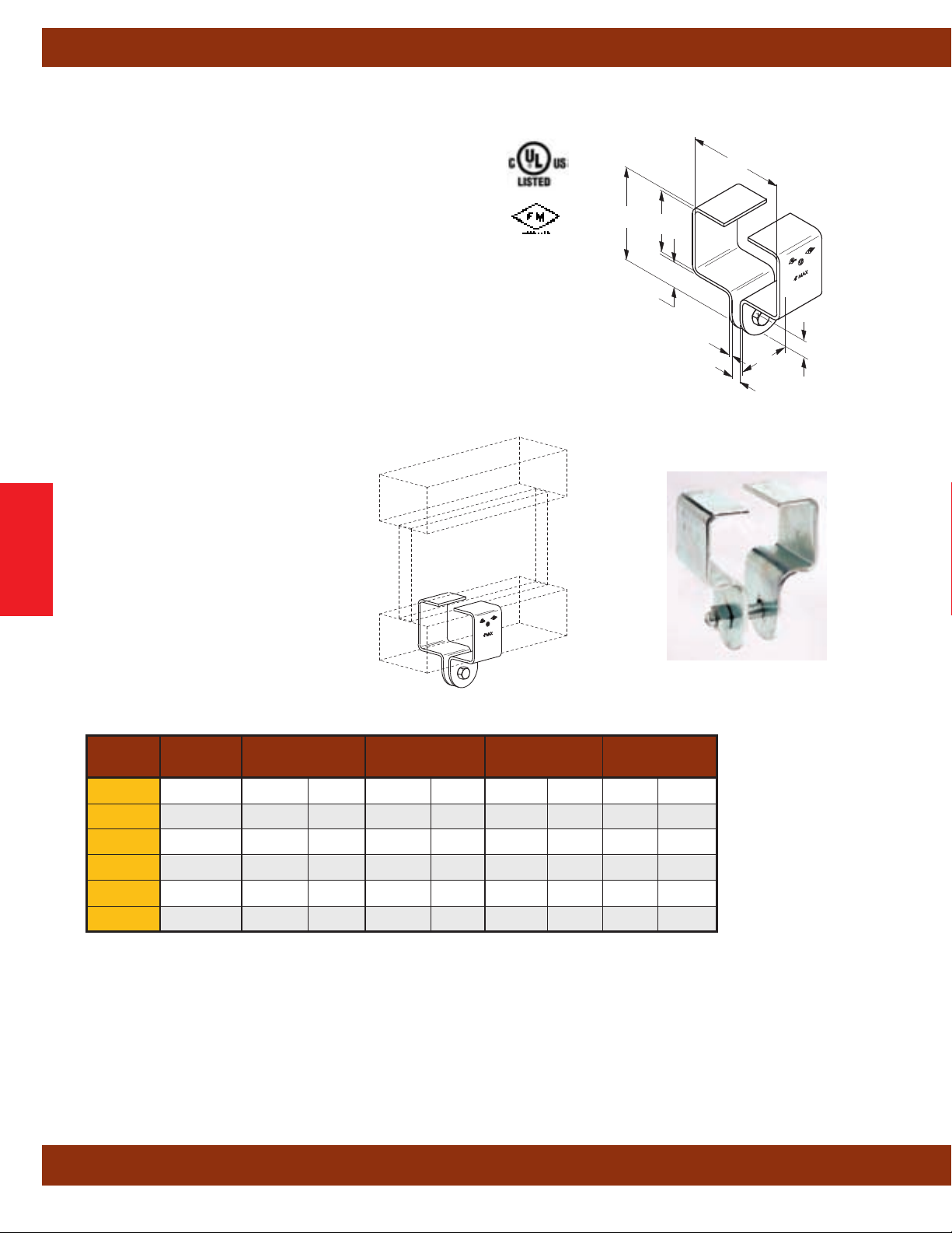
Beam Clamps
Fig. 130 - Beam Clamp with Bolt and Nut (Cooper B-Line Fig. B3052)
Size Range: 130-1 = TJI 35
130-2 = ––
130-3 = TJI 25
130-4 = TJI 55 & 65
130-5 = TJI 75
130-6 = TJI 96
Material: Steel
Function: Designed for attachment to trus joist beams.
Use with B3210 Series eye rods.
Approvals: Sizes 1 - 6 are Underwriters Laborarories
Listed in the USA (UL) and Canada (cUL) list through
4”
(100mm) pipe. All Fig. 130 Beam Clamps meet
requirements of Factory Mutual Engineering and NFPA 13,
through 4”
(100mm) pipe.
Finish: Electro-Galvanized or Hot-Dip Galvanized
Order By: Figure number and finish.
Hardware
Included
A
H
1"
(25.4)
Material Thickness
11 Gauge
1
/8"
(3.2)
(3.0)
W
2"
(50.8)
3
/4"
3
/8"
(19.0)
(9.5)
Beam Clamps
130-1
130-2
130-3
130-4
130-5
130-6
‘H’ and ‘W’ are beam dimensions.
* Maximum Recommended Load 500 Lbs.
† Larger bolts and I-rods are required for 5” (125mm) and 6” (150mm) pipe sizes
Part Hardware A H W Approx. Wt./100
No. Size
3
/8”-16 31/4" (82.5) 11/2" (38.1) 25/16" (58.7) 65 (29.5)
3
/8”-16 31/2" (88.9) 13/4" (44.4) 21/2" (63.5) 70 (31.7)
3
/8”-16 31/4" (82.5) 11/2" (38.1) 13/4" (44.4) 58 (26.3)
3
/8”-16 31/2" (88.9) 11/2" (38.1) 31/2" (88.9) 83 (37.6)
†
†
1
/2”-13 35/8" (92.1) 13/4" (44.4) 31/2" (88.9) 86 (39.0)
1
/2”-13 41/2" (114.3) 21/2" (63.5) 37/8" (98.4) 101 (45.8)
in. (mm) in. (mm) in. (mm) Lbs. (kg)
(2.22kN) Safety Factor of 5
All dimensions in charts and on drawings are in inches. Dimensions shown in parentheses are in millimeters unless otherwise specified.
44
Page 47

Beam Clamps
Beam Clamps
All dimensions in charts and on drawings are in inches. Dimensions shown in parentheses are in millimeters unless otherwise specified.
45
Page 48

Pipe Hangers
Pipe Hangers
Pipe hangers offered in this section are designed to support insulated or non-insulated pipe allowing for vertical
adjustment and limited movement in the piping system.
Materials
Carbon Steel, Malleable Iron and AISI Type 304 & 316 Stainless Steel are used in the manufacturing of pipe
hangers. Other materials are available.
Finishes
The standard finishes for mechanical supports are plain steel (oil coated) sometimes referred to as black,
Electro-Galvanized Zinc (ASTM B 633 SC3), Pre-Galvanized (ASTM A 653 G90), Hot-Dip Galvanized After Fabrication
(ASTM A123), Red Primer, Plastic Coating, DURA-GREEN
available upon request.
Note: Due to the design of some products, (threads, connecting hardware, swivels, etc.) items may or may not
be uniformly coated with special finishes i.e. Hot-Dip Galvanized, DURA-GREEN, DURA-COPPER, PVC etc. In some
cases, the hanger itself may be coated, however, the hardware may be supplied Electro-Plated, DURA-COPPER
Painted or Stainless Steel. Consult B-Line Systems for availability.
™
, DURA-COPPER™and other special coatings are
Approvals (as noted)
Items in this section are Underwriters Laboratories Listed, Factory Mutual Approved, and comply with Federal
Specification WW-H-171E & A-A-1192A or Manufacturers Standardization Society ANSI/MSS SP-69 & SP-58.
Seismic Restraints Catalog approved by the State of California Office of Statewide Health Planning and Development
(OSHPD)
All dimensions in charts and on drawings are in inches. Dimensions shown in parentheses are in millimeters unless otherwise specified.
46
Page 49

Fig. 1CBS - Clevis Pipe Spacer (Cooper B-Line B3100PS)
Pipe Hangers
Size Range: Size 1" (25mm) thru 20" (500mm) clevis hanger
Material: Steel
Function: Used as a spacer at a seismic brace location to
keep clevis hanger from collapsing during seismic event.
Approvals: Included in our Seismic Restraints Catalog
approved by the State of California Office of Statewide
Health Planning and Development (OSHPD). For additional
load, spacing and placement information relating to OSHPD
projects, please refer to the Cooper B-Line/T
Restraint
Systems Guidelines.
Installation Note: Fig. 1CBS fits easily over the cross bolt
and attaches by pinching tabs down.
Finish: Pre-Galvanized. Contact Cooper B-Line for alternative
finishes and materials.
Order By:
Figure
number and finish.
Pipe Size Approx. Wt./100
Part No.
1CBS-1 1” (25) 3.2 (1.4)
1CBS-11/4 11/4” (32) 4.1 (1.8)
1CBS-11/2 11/2” (40) 4.8 (2.2)
1CBS-2 2” (50) 9.4 (4.2)
1CBS-21/2 21/2” (65) 11.4 (5.2)
1CBS-3 3” (75) 13.9 (6.8)
1CBS-31/2 31/2” (90) 16.0 (7.2)
1CBS-4 4” (100) 18.0 (8.1)
1CBS-5 5” (125) 27.3 (12.4)
1CBS-6 6” (150) 32.5 (14.7)
1CBS-8 8” (200) 42.5 (19.2)
1CBS-10 10” (250) 72.7 (32.9)
1CBS-12 12” (300) 86.3 (39.1)
1CBS-14 14” (350) 157.6 (71.5)
1CBS-16 16” (400) 183.7 (83.3)
1CBS-18 18” (450) 224.6 (101.9)
1CBS-20 20” (500) 254.0 (115.2)
in. (mm) lbs. (kg)
OLCO Seismic
™
Component of State of
California OSHPD Approved
Seismic Restraints System
Pipe Hangers
All dimensions in charts and on drawings are in inches. Dimensions shown in parentheses are in millimeters unless otherwise specified.
47
Page 50
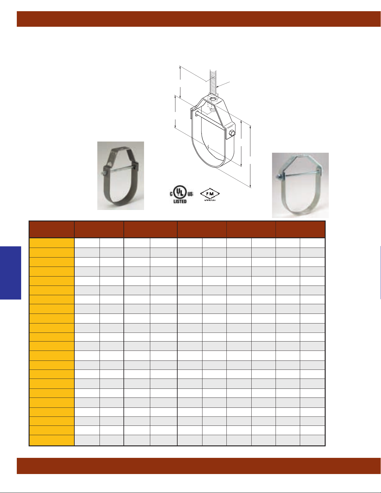
Pipe Hangers
Fig. B3100 - Standard Clevis Hanger (TOLCO Fig.1)
SLIDE-RITE™ Clevis Hanger Features
Pipe will not ‘pinch’ when installing.
swing in either direction allows pipe to easily
15°
feed thru.
Engineered design aligns bolt holes for quicker
overhead installation.
*SLIDE-RITE™ Clevis Hanger
design, as shown below, for
sizes 2, 2
1
/2, 3, 4, 5 & 6.
Pat. No. 5,848,770
5,924,655
D
A
E
(Rod Size)
Hanger Rod Not
Included
C
B
Bottom of pipe to top of hanger.
Center of pipe to top of hanger.
Center of pipe to bottom of
Minimum thread length of
Top of cross bolt to bottom of hanger
rod nut inside the hanger.
B
C
D
Rod Take-Out
hanger rod.
E
hanger rod
F
Adjustment
Part No. in. (mm) Std NFPA** in. (mm) in. (mm) in. (mm)
B3100-1/2
Pipe Hangers
B3100-3/4
B3100-1 1" (25)
B3100-11/4 11/4" (32)
B3100-11/2 11/2" (40)
B3100-2 * 2" (50)
B3100-21/2 * 21/2" (65)
B3100-3 * 3" (80)
B3100-31/2 31/2" (90)
B3100-4 * 4" (100)
B3100-5 * 5" (125)
B3100-6 * 6" (150)
B3100-8 8" (200)
B3100-10 10" (250)
B3100-12 12" (300)
B3100-14 14" (350) 1"-8 -- 199/16"
B3100-16 16" (400) 1"-8 -- 217/16"
B3100-18 18" (450) 1"-8 -- 25"
B3100-20 20" (500) 11/4"-7 -- 271/2"
B3100-24 24" (600) 11/4"-7 -- 313/4"
B3100-30 30" (750) 11/4"-7 -- 387/8"
B3100-36 36" (900) 11/4"-7 -- 46"
Nominal Pipe Size Rod Size A B C D
1
/2" (15)
3
/4" (20)
3
/8"-16
3
/8"-16
3
/8"-16
3
/8"-16
3
/8"-16
3
/8"-16
1
/2"-13
1
/2"-13
1
/2"-13
5
/8"-11
5
/8"-11
3
/4"-10
3
/4"-10
7
/8"-9
7
/8"-9
3
/8"-16 21/8" (54.0) 111/16" (42.9)
3
/8"-16 27/16" (61.9) 17/8" (47.6) 11/8" (28.6)
3
/8"-16 213/16" (71.4) 21/8" (54.0) 13/8" (34.9)
3
/8"-16 37/16" (87.3) 29/16" (65.1) 113/16" (46.0)
3
/8"-16 4" (101.6)` 3" (76.2) 21/4" (57.1)
3
/8"-16 41/2" (114.3) 31/4" (82.5) 21/2" (63.5)
3
/8"-16 59/16" (141.3) 4" (101.6) 31/16" (77.8)
3
/8"-16 63/4" (171.4) 47/8" (123.8) 315/16" (100.0)
3
/8"-16 7" (177.8) 5" (127.0) 41/16" (103.2)
3
/8"-16 713/16"
1
/2"-13 91/16"
1
/2"-13 107/16"
1
/2"-13 123/4"
5
/8"-11 151/4"
5
/8"-11 175/8"
(198.4)
(230.2)
(265.1)
(323.8)
(387.3)
(447.7)
(496.9)
(544.5)
(635.0)
(698.5)
(806.4)
(987.3)
(1168.4)
51/2" (139.7) 43/8" (111.1)
61/8" (155.6) 5" (127.0)
615/16" (176.2) 511/16" (144.5)
83/8" (212.7) 71/8" (181.0)
913/16" (249.2) 83/8" (212.7)
113/16" (284.2) 911/16" (246.1)
121/2" (317.5) 105/8" (269.9)
135/16" (338.1) 119/16" (293.7)
157/8" (403.2) 143/16" (360.3)
173/8" (441.3) 165/8" (422.3)
195/8" (498.5) 185/8" (473.1)
233/4" (603.2) 223/4" (577.8)
2713/16" (706.4) 25" (635.0)
15
/16" (23.8)
All dimensions in charts and on drawings are in inches. Dimensions shown in parentheses are in millimeters unless otherwise specified.
48
Page 51
Pipe Hangers
Fig. B3100 - Standard Clevis Hanger (TOLCO Fig.1)
Size Range:1/2” (15mm) to 36” (900mm)
Material: Steel
Function: Recommended for the suspension of non-insulated pipe or insulated pipe with a B3151 shield.
Note: When an oversized clevis is used, a pipe spacer should be placed over the cross bolt to assure that the
lower U-strap will not move in on the bolt. When attaching seismic bracing to the clevis hangers, a B3100PS
(cross bolt spacer) must be installed. See Seismic Restraints
Order pipe sleeves Fig. 1CBS-(pipe size) separately.
Approvals: Underwriter's Laboratories Listed in the USA (UL) and Canada (cUL) for sizes
Factory Mutual Engineering Approved (FM) for
3
/4” (20mm) thru 8” (200mm) pipe.
WW-H-171E & A-A-1192A, Type 1 and Manufacturers Standardization Society ANSI/MSS SP-69 & SP-58, Type 1.
Also available to accommodate rod schedule per per National Fire Protection Association (NFPA) Pamphlet 13.
Maximum Temperature: 650°F
(343°C).
Standard Finish: Plain, Electro-Galvanized, DURA-GREEN
also available in Stainless Steel
Figure
Order By:
number and finish.
For AWWA - Ductile Iron Clevis Hangers, see B3102, page 50.
Approval Guidelines.
Conforms to Federal Specification
™
, or Hot-Dip Galvanized
1
/2" (15) thru 12" (300).
** Note: Do not use the dimensions shown in the B3100 chart for NFPA hanger sizes.
Contact Cooper B-Line for NFPA rod sizing on
1
/2” (15mm) thru 12” (300mm) pipe.
Part numbers will be 1NFPA-pipe size.
E Adjustment F Design Load Approx. Wt./100
Part No. in. (mm) in. (mm) Lbs. (kN) Lbs. (kg)
B3100-1/2 21/2" (63.5)
B3100-3/4 21/2" (63.5)
B3100-1 21/2" (63.5)
B3100-11/4 21/2" (63.5)
7
/16" (11.1) 730 (3.25) 25 (11.3)
1
/2" (12.7) 730 (3.25) 29 (13.1)
5
/8" (15.9) 730 (3.25) 35 (15.9)
7
/8" (22.2) 730 (3.25) 40 (18.1)
B3100-11/2 21/2" (63.5) 13/16" (30.2) 730 (3.25) 42 (19.0)
B3100-2 * 21/2" (63.5) 15/8" (41.3) 730 (3.25) 52 (23.6)
B3100-21/2 * 21/2" (63.5) 2" (50.8) 1350 (6.00) 90 (40.8)
B3100-3 * 21/2" (63.5) 2" (50.8) 1350 (6.00) 110 (49.9)
B3100-31/2 21/2" (63.5) 2" (50.8) 1350 (6.00) 142 (64.4)
B3100-4 * 21/2" (63.5) 2" (50.8) 1430
B3100-5 * 21/2" (63.5) 2" (50.8) 1430
B3100-6 * 3" (76.2) 2" (50.8) 1940
B3100-8 31/2" (88.9) 25/16" (58.7) 2000
B3100-10 31/2" (88.9) 25/16" (58.7) 3600
B3100-12 31/2" (88.9) 25/8" (66.7) 3800
B3100-14 4" (101.6) 27/8" (73.0) 4200
B3100-16 4" (101.6) 211/16" (68.3) 4600
B3100-18 41/2" (114.3) 315/16" (100.0) 4800
B3100-20 5" (127.0) 53/8" (136.5) 4800
B3100-24 5" (127.0) 53/8" (136.5) 4800
B3100-30 5" (127.0) 61/4" (158.7) 6000
B3100-36 5" (127.0 57/16" (138.1) 6000
(6.36) 132 (59.9)
(6.36) 215 (97.5)
(8.63) 320 (145.1)
(8.89) 485 (220.0)
(16.01) 846 (383.7)
(16.90) 1083 (491.2)
(18.68) 1432 (649.5)
(20.46) 2200 (997.9)
(21.35) 2500 (1134.0)
(21.35) 4400 (1995.8)
(21.35) 5000 (2268.0)
(26.69) 6600 (2993.7)
(26.69) 8474 (3843.8)
*SLIDE-RITE™ Clevis Hanger design, as shown above, for sizes 2, 21/2, 3, 4, 5 & 6.
All dimensions in charts and on drawings are in inches. Dimensions shown in parentheses are in millimeters unless otherwise specified.
Pipe Hangers
49
Page 52

Pipe Hangers
Fig. B3102 - A.W.W.A. Clevis Hanger (TOLCO Fig.1CI)
Size Range: 4” (100mm) to 24”
(600mm)
Material: Steel
Function: Recommended for the suspension of
flanged or bell and spigot
A.W.W.A. cast iron or
ductile iron pipe. The O.D. of the A.W.W.A. iron pipe
is shown in the data table.
Approvals: Conforms to Federal Specification
-H-171E & A-A-1192A, Type 1 and
WW
Manufacturers Standardization Society ANSI/MSS
SP-69 & SP-58, Type 1.
Standard Finish: Plain & Electro-Galvanized.
Contact Cooper B-Line for alternative finishes and
materials.
Order By: Figure number and finish.
A
(Rod Size)
Hanger Rod Not
E
D
Included
C
B
Bottom of pipe t0 top of hanger.
Center of pipe to top of hanger.
Center of pipe to bottom of
Minimum thread length of
Top of cross bolt to bottom of hanger
rod nut inside the hanger.
B
C
D
Rod Take-Out
hanger rod.
E
hanger rod
F
Adjustment
Pipe Hangers
Pipe O.D. Rod Size B C D E F Design Load
Part No. in. (mm) A in. (mm) in. (mm) in. (mm) in. (mm) in. (mm) Lbs. (kN) Lbs. (kg)
B3102-4 4.80 (121.9)5/8"-11 85/16" (211.1) 513/16" (147.6) 45/8" (117.5) 21/2" (63.5) 2" (50.8) 1430
B3102-6 6.90 (175.2)3/4"-10 105/8" (269.9) 71/16" (179.4) 513/16" (147.6) 3" (76.2) 2" (50.8) 1940
B3102-8 9.05 (229.9)3/4"-10 131/4" (336.5) 85/8" (219.1) 73/16" (182.5) 31/2" (88.9) 21/8" (54.0) 2000
B3102-10 11.10 (281.9)7/8"-9 157/8" (403.2) 101/4" (260.3) 811/16" (220.6) 31/2" (88.9) 21/4" (57.1) 3600
B3102-12 13.20 (335.3)7/8"-9 18" (457.2) 115/16" (287.3) 93/4" (247.6) 31/2" (88.9) 21/4" (57.1) 3800
B3102-14 15.30 (388.6) 1"-8 203/8" (517.5) 125/8" (320.7) 113/16" (281.6) 4" (101.6) 27/8" (73.0) 4200
B3102-16 17.40 (441.9) 1"-8 231/2" (569.9) 1411/16" (373.1) 127/8" (327.0) 4" (101.6) 33/8" (85.7) 4600
B3102-18 19.50 (495.3) 1"-8 255/8" (650.9) 153/4" (400.0) 1315/16" (354.0) 41/2" (114.3) 33/8" (85.7) 4800
B3102-20 21.60 (548.6) 11/4"-7 291/2" (749.3) 189/16" (471.5) 177/16" (442.9) 5" (127.0) 413/16" (122.2) 4800
B3100-24 25.80 (655.3) 11/4"-7 33" (838.2) 191/8" (508.0) 20" (485.8) 5" (127.0) 51/4" (133.3) 4800
(6.36) 203 (92.1)
(8.63) 352 (159.6)
(8.89) 532 (241.3)
(16.01) 800 (362.9)
(16.90) 1152 (522.5)
(18.68) 1449 (657.2)
(20.46) 2100 (952.6)
(21.35) 2294 (1040.5)
(21.35) 3887 (1763.1)
(21.35) 4844 (2197.2)
Approx. Wt./100
All dimensions in charts and on drawings are in inches. Dimensions shown in parentheses are in millimeters unless otherwise specified.
50
Page 53
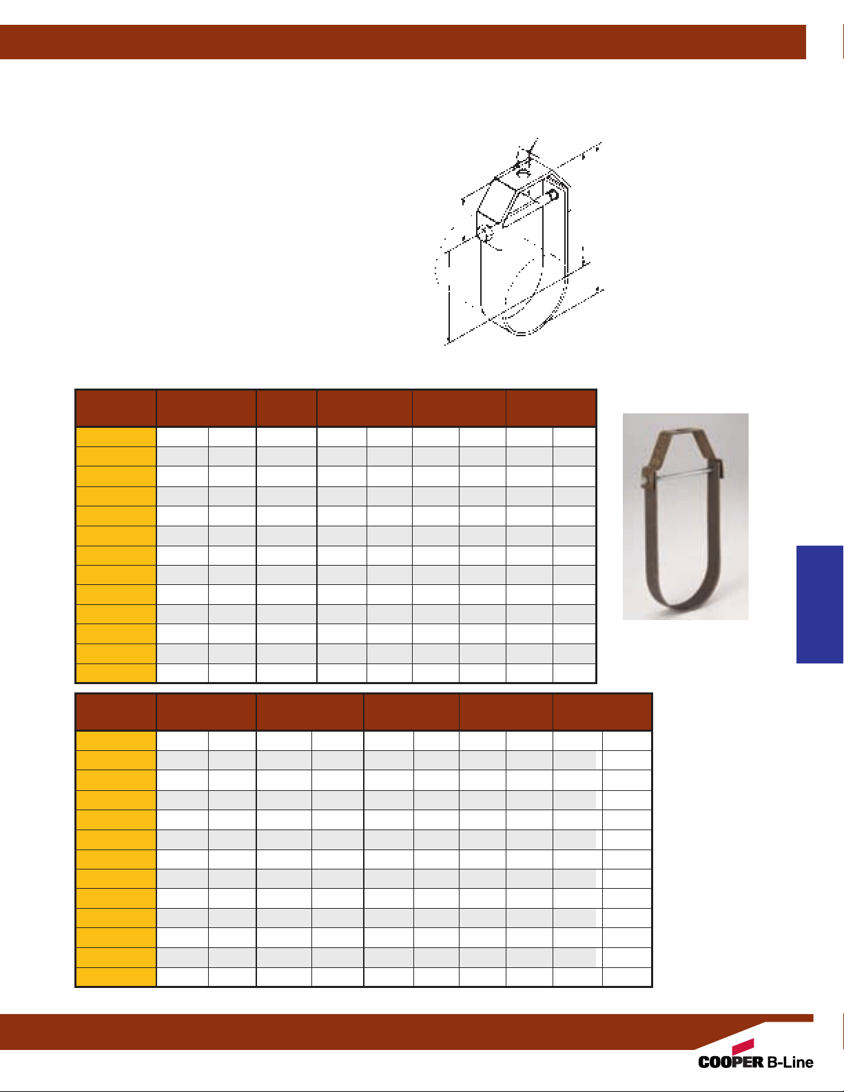
Pipe Hangers
Fig. B3108 - Extended Clevis Hanger (TOLCO Fig.1A)
Size Range:3/4” (20mm) thru 12”
Material: Steel
Function: Recommended for the suspension of insulated
pipe where the temperature does not require the use of
slides, guides, or rollers for movement.
Approvals: Conforms to Federal Specification WW-H-171E
A-A-1192A, Type 1 and Manufacturers Standardization
&
Society ANSI/MSS SP-69 & SP-58, Type 1.
Maximum Temperature: 650°F
Order By: Figure number and finish. For service
For Stainless Steel add SS to part number
Standard Finish: Plain, Electro-Galvanized or Hot Dip
Galvanized
For service temperatures of 750°F (399°C) thru
1050°F (565°C) specify
Type 304 Stainless Steel
Nominal Pipe Size Rod Size B C D
Part No. in. (mm) A in. (mm) in. (mm) in. (mm)
B3108-3/4
3
/4" (20)
B3108-1 1" (25)
B3108-11/4 11/4" (32)
B3108-11/2 11/2" (40)
B3108-2 2" (50)
B3108-21/2 21/2" (65)
B3108-3 3" (80)
B3108-4 4" (100)
B3108-5 5" (125)
B3108-6 6" (150)
B3108-8 8" (200)
B3108-10 10" (250)
B3108-12 12" (300)
(300mm)
(343°C).
pipe
E
.
3
/8"-16 43/8" (111.1) 313/16" (96.8) 31/16" (77.8)
3
/8"-16 43/4" (120.6) 41/16" (103.2) 31/4" (82.5)
3
/8"-16 53/8" (136.5) 41/2" (114.3) 35/16" (84.1)
3
/8"-16 67/8" (174.6) 515/16" (150.8) 51/8" (130.2)
3
/8"-16 813/16" (223.8) 75/8" (193.7) 67/8" (174.6)
1
/2"-13 10" (254.0) 81/2" (215.9) 79/16" (192.1)
1
/2"-13 105/8" (269.9) 813/16" (223.8) 77/8" (200.0)
5
/8"-11 1113/16"
5
/8"-11 131/8"
3
/4"-10 143/8"
3
/4"-10 163/4"
7
/8"-9 191/4"
7
/8"-9 215/8"
(300.0)
(333.4)
(365.1)
(425.4)
(488.9)
(549.3)
D
91/2" (241.3) 83/8" (212.7)
105/16" (261.9) 91/8" (231.8)
11" (279.5) 911/16" (246.0)
123/8" (314.3) 111/8" (282.6)
1313/16" (350.8) 125/16" (312.7)
153/16" (385.8) 135/8" (346.1)
Hanger Rod Not
A
(Rod Size)
Included
Bottom of pipe to top of hanger.
Center of pipe to top of hanger.
C
B
Center of pipe to bottom of
Minimum thread length of
Top of cross bolt to bottom of
hanger rod nut inside the hanger.
Maximum insulation thickness.
B
C
D
Rod Take-Out
hanger rod.
E
hanger rod.
F
Adjustment
H
Pipe Hangers
E F H Design Load Approx. Wt./100
Part No.
B3108-3/4 21/2" (63.5)
B3108-1 21/2" (63.5)
B3108-11/4 21/2" (63.5)
in. (mm) in. (mm) in. (mm) lbs. (kN) lbs. (kg)
1
/2" (12.7) 2" (50.8) 730 (3.25) 45 (20.4)
5
/8" (15.9) 2" (50.8) 730 (3.25) 49 (22.2)
7
/8" (22.2) 2" (50.8) 730 (3.25) 55 (24.9)
B3108-11/2 21/2" (63.5) 13/16" (30.2) 2" (50.8) 730 (3.25) 67 (30.4)
B3108-2 21/2" (63.5) 15/8" (41.3) 4" (101.6) 730 (3.25) 83 (37.6)
B3180-21/2 21/2" (63.5) 2" (50.8) 4" (101.6) 1350 (6.00) 177 (80.3)
B3108-3 21/2" (63.5) 2" (50.8) 4" (101.6) 1350 (6.00) 191 (86.6)
B3108-4 21/2" (63.5) 2" (50.8) 4" (101.6) 1430 (6.36) 237 (107.5)
B3108-5 21/2" (63.5) 2" (50.8) 4" (101.6) 1430 (6.36) 302 (137.0)
B3108-6 3" (76.2) 2" (50.8) 4" (101.6) 1940 (8.63) 397 (180.1)
B3108-8 31/2" (88.9) 25/16" (58.7) 4" (101.6) 2000 (8.89) 582 (264.0)
B3108-10 31/2" (88.9) 25/16" (58.7) 4" (101.6) 3600 (16.01) 968 (439.1)
B3108-12 31/2" (88.9) 25/8" (66.7) 4" (101.6) 3800 (16.90) 1221 (553.8)
All dimensions in charts and on drawings are in inches. Dimensions shown in parentheses are in millimeters unless otherwise specified.
51
Page 54
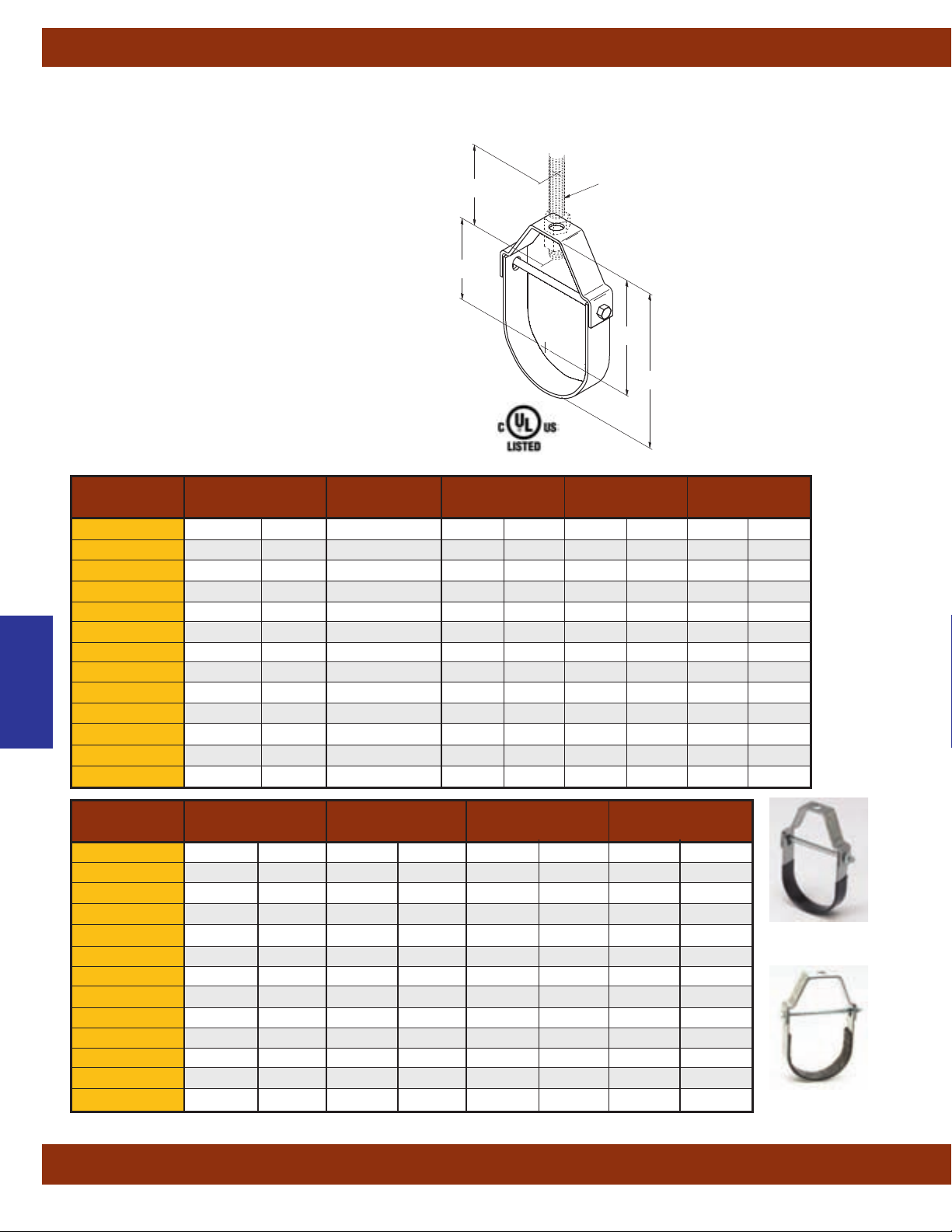
Pipe Hangers
Fig. B3100C - Standard Clevis Hanger - Plastic Coated (TOLCO Fig.1PVC)
Fig. B3100F - Standard Clevis Hanger - Felt Lined (TOLCO Fig.1F)
Size Range:1/2” (15mm) to 8”
(200mm)
pipe
Material: Steel
3
Insulation Material:
/16” (4.8mm) Felt
Service: The B3100F is designed for the suspension of
copper tube so as to prevent electrolysis between tubing
and hanger
. The B3100C is designed for steel or other
pipe types of the same O.D. Both B3100F and B3100C
act to reduce noise and vibration in pipe or tubing
systems.
Appr
ovals: Underwriter's Laboratories Listed in the USA
(UL) and Canada (cUL).
Maximum Temperature: 650°F
(343°C).
Standard Finish: Plain, Electro-Galvanized, or Hot-Dip
Galvanized. Contact Cooper B-Line for alternative finishes
and materials.
Order By: Figure number and finish.
Pipe Size Rod Size B CD
Part No. in. (mm) A in. (mm) in. (mm) in. (mm)
B3100-1/2
B3100-3/4
1
/2" (15)
3
/4" (20)
B3100-1 1" (25)
B3100-11/4 11/4" (32)
B3100-11/2 11/2" (40)
Pipe Hangers
B3100-2 2" (50)
B3100-21/2 21/2" (65)
B3100-3 3" (80)
B3100-31/2 31/2" (90)
B3100-4 4" (100)
B3100-5 5" (125)
B3100-6 6" (150)
B3100-8 8" (200)
A
E
D
3
/8"-16 21/8" (54.0) 111/16" (42.9)
3
/8"-16 27/16" (61.9) 17/8" (47.6) 11/8" (28.6)
3
/8"-16 213/16" (71.4) 21/8" (54.0) 13/8" (34.9)
3
/8"-16 37/16" (87.3) 29/16" (65.1) 113/16" (46.0)
3
/8"-16 4" (101.6)` 3" (76.2) 21/4" (57.1)
3
/8"-16 41/2" (114.3) 31/4" (82.5) 21/2" (63.5)
1
/2"-13 59/16" (141.3) 4" (101.6) 31/16" (77.8)
1
/2"-13 63/4" (171.4) 47/8" (123.8) 315/16" (100.0)
1
/2"-13 7" (177.8) 5" (127.0) 41/16" (103.2)
5
/8"-11 713/16"
5
/8"-11 91/16"
3
/4"-10 107/16"
3
/4"-10 123/4"
(198.4)
(230.2)
(265.1)
(323.8)
(Rod Size)
Hanger Rod Not
Included
C
B
51/2" (139.7) 43/8" (111.1)
61/8" (155.6) 5" (127.0)
615/16" (176.2) 511/16" (144.5)
83/8" (212.7) 71/8" (181.0)
Bottom of pipe to top of hanger.
Center of pipe to top of hanger.
Center of pipe to bottom of
Minimum thread length of
Top of cross bolt to bottom of hanger
rod nut inside the hanger.
15
/16" (23.8)
B
C
D
Rod Take-Out
hanger rod.
E
hanger rod
F
Adjustment
E Adjustment F Design Load Approx. Wt./100
Part No. in. (mm) in. (mm) Lbs. (kN) Lbs. (kg)
B3100-1/2 21/2" (63.5)
B3100-3/4 21/2" (63.5)
B3100-1 21/2" (63.5)
B3100-11/4 21/2" (63.5)
7
/16" (11.1) 730 (3.25) 25 (11.3)
1
/2" (12.7) 730 (3.25) 29 (13.1)
5
/8" (15.9) 730 (3.25) 35 (15.9)
7
/8" (22.2) 730 (3.25) 40 (18.1)
B3100-11/2 21/2" (63.5) 13/16" (30.2) 730 (3.25) 42 (19.0)
B3100-2 21/2" (63.5) 15/8" (41.3) 730 (3.25) 52 (23.6)
B3100-21/2 21/2" (63.5) 2" (50.8) 1350 (6.00) 90 (40.8)
B3100-3 21/2" (63.5) 2" (50.8) 1350 (6.00) 110 (49.9)
B3100-31/2 21/2" (63.5) 2" (50.8) 1350 (6.00) 142 (64.4)
B3100-4 21/2" (63.5) 2" (50.8) 1430
B3100-5 21/2" (63.5) 2" (50.8) 1430
B3100-6 3" (76.2) 2" (50.8) 1940
B3100-8 31/2" (88.9) 25/16" (58.7) 2000
All dimensions in charts and on drawings are in inches. Dimensions shown in parentheses are in millimeters unless otherwise specified.
(6.36) 132 (59.9)
(6.36) 215 (97.5)
(8.63) 320 (145.1)
(8.89) 485 (220.0)
52
B3100C
B3100F
Page 55
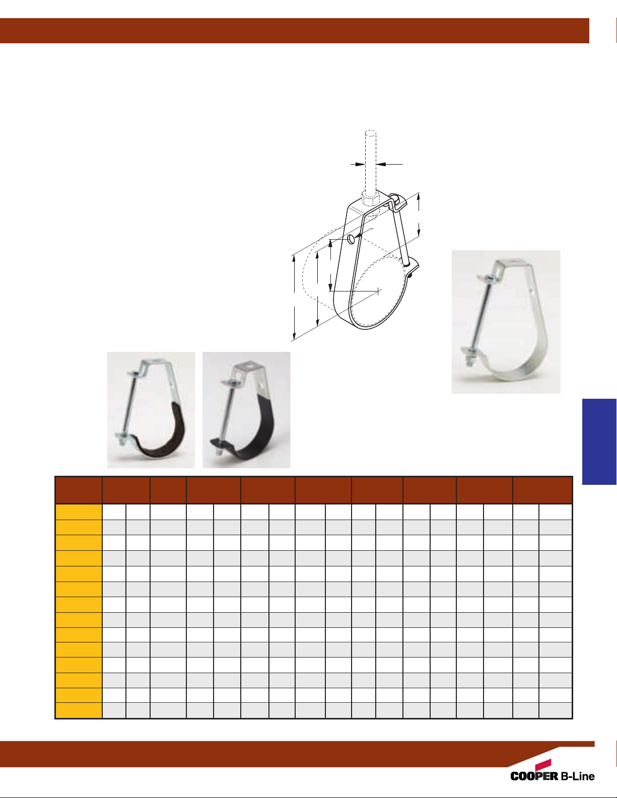
Fig. B3690 - J-Hanger for Pipe or Conduit (TOLCO Fig. 3)
Fig. B3690F - Felt Lined J-Hanger for Copper Tubing (TOLCO Fig. 3F)
Fig. B3690C - PVC Coated J-Hanger for Pipe or Conduit (TOLCO Fig. 3PVC)
Pipe Hangers
Size Range:1/2” (15mm) to 10”
(250mm)
pipe size
Material: Steel
Function: Recommended for the suspension of
non-insulated pipe, or insulated pipe with B3151 shield.
Side hole allows for wall mounting.
B3690F and B3690C are designed to reduce noise and
vibration and/or prevent electrolysis between pipe and
hanger
.
Approvals: Conforms to Federal Specification
-H-171E & A-A-1192A, Type 5 and Manufacturers
WW
Standardization Society ANSI/MSS SP-69 & SP-58,
Type 5. Included in our Seismic Restraints Catalog
approved by the State of California Office of Statewide
Health Planning and Development (OSHPD). For
additional load, spacing and placement information
relating to OSHPD projects, please refer to the Cooper
B-Line/T
OLCO Seismic Restraint Systems Guidelines.
Standard Finish: Plain & Electro-Plated. Contact
Cooper B-Line for alternative finishes and materials.
Order By: Figure number and finish.
Hanger Rod Not
B
A
(Rod Size)
Included
E
F
Component of State of
California OSHPD Approved
Seismic Restraints System
B
Center of pipe to top of hanger.
F
Rod Take-Out
Center of pipe to bottom of
hanger rod.
C
D
Dia.
B3690F
Pipe O.D. Rod Size B C D E F Design Load
B3690C
Approx. Wt./100
Part No. in. (mm) A in. (mm) in. (mm) in. (mm) in. (mm) in. (mm) Lbs. (kN) Lbs. (kg)
B3690-1/21/2" (15)3/8"-16 25/8" (66.7) 13/4" (44.4) 7/16" (11.1) 11/2" (38.1) 15/16" (33.3) 400
B3690-3/43/4" (20)3/8"-16 27/8" (73.0) 17/8" (47.6) 7/16" (11.1) 111/16" (42.9) 21/8" (54.0) 400
B3690-1 1" (25)3/8"-16 215/16" (74.6) 115/16" (49.2) 7/16" (11.1) 113/16" (46.0) 25/16" (58.7) 400
B3690-11/4 11/4" (32)3/8"-16 31/4" (82.5) 2" (50.8) 7/16" (11.1) 21/16" (52.4) 25/8" (66.7) 400
B3690-11/2 11/2" (40)3/8"-16 39/16" (90.5) 23/16" (55.6) 7/16" (11.1) 27/16" (61.9) 27/8" (73.0) 400
B3690-2 2" (50)3/8"-16 311/16" (93.7) 21/8" (54.0) 7/16" (11.1) 29/16" (65.1) 31/16" (77.8) 400
B3690-21/2 21/2" (65)1/2"-13 47/16" (112.7) 27/16" (61.9) 9/16" (14.3) 33/16" (81.0) 35/8" (92.1) 500
B3690-3 3" (80)1/2"-13 413/16" (122.2) 29/16" (65.1) 9/16" (14.3) 31/2" (88.9) 41/16" (103.2) 500
B3690-31/2 31/2" (90)1/2"-13 51/8" (130.2) 25/8" (66.7) 9/16" (14.3) 33/4" (95.2) 43/8" (111.1) 500
B3690-4 4" (100)5/8"-11 61/8" (155.6) 33/16" (81.0) 9/16" (14.3) 45/8" (117.5) 53/16" (131.8) 550
B3690-5 5" (125)5/8"-11 63/4" (171.4) 31/4" (82.5) 9/16" (14.3) 51/16" (128.6) 53/4" (146.0) 550
B3690-6 6" (150)3/4"-10 73/4" (196.8) 39/16" (90.5) 9/16" (14.3) 513/16" (147.6) 65/8" (168.3) 600
B3690-8 8" (200)7/8"-9 93/16" (233.4) 315/16" (100.0) 9/16" (14.3) 615/16" (176.2) 8" (203.3) 760
B3690-10 10" (250)7/8"-9 103/4" (273.0) 37/8" (98.4) 9/16" (14.3) 75/8" (193.7) 91/8" (231.8) 760
All dimensions in charts and on drawings are in inches. Dimensions shown in parentheses are in millimeters unless otherwise specified.
(1.78) 18 (8.1)
(1.78) 21 (9.5)
(1.78) 22 (10.0)
(1.78) 25 (11.3)
(1.78) 27 (12.2)
(1.78) 29 (13.1)
(2.22) 64 (29.0)
(2.22) 72 (32.6)
(2.22) 84 (38.1)
(2.44) 138 (62.6)
(2.44) 162 (73.5)
(2.67) 249 (112.9)
(3.38) 291 (132.0)
(3.38) 315 (142.9)
Pipe Hangers
53
Page 56
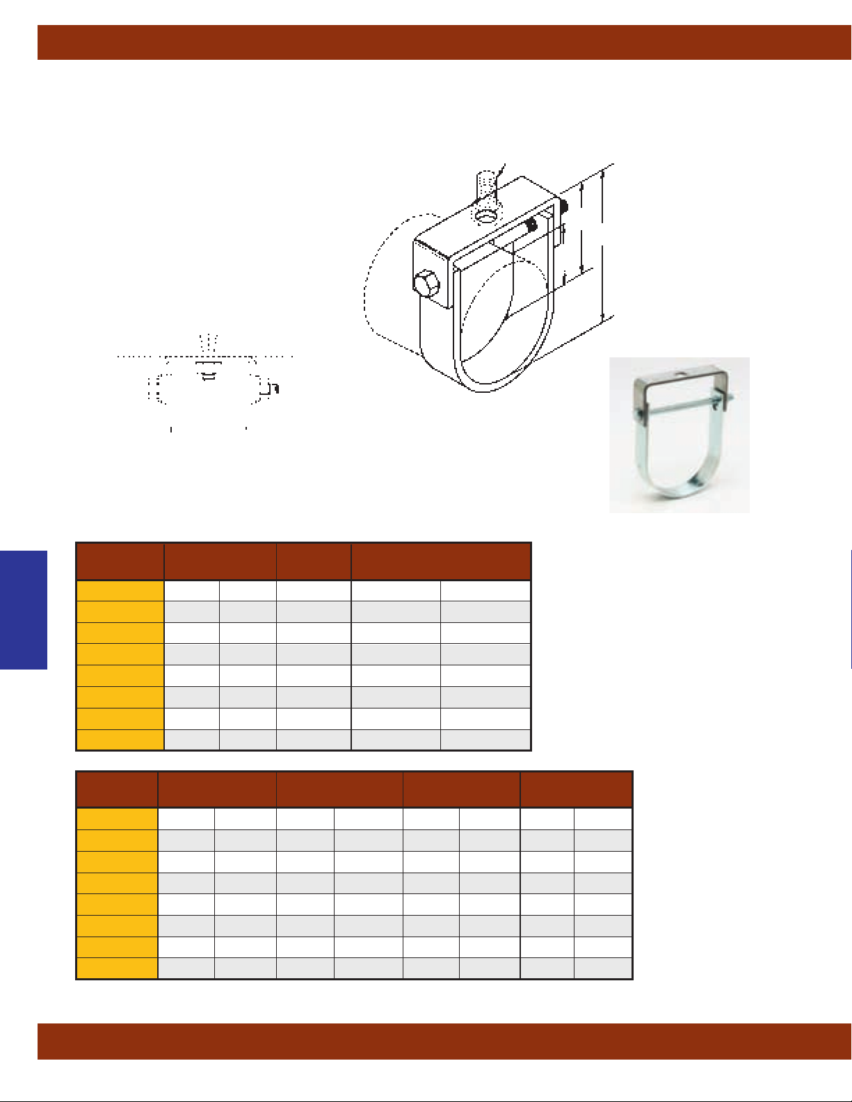
Pipe Hangers
Fig. B3109 - Flat Top Clevis Hanger
Size Range: 2” (50mm) to 8”
(200mm)
pipe size
Material: Steel
Function: Recommended for suspending non-
insulated, stationary pipe where space is limited.
Approvals: Complies with Manufacturers
Standardization Society
ANSI/MSS SP-69 & SP-58
Type 1.
Standard Finish: Plain or Electro-Galvanized
Order By: Figure number and finish.
A
(Rod Size)
Hanger Rod Not
Included
D
B
Bottom of pipe
to top of hanger.
C
C
B
Center of pipe
to top of hanger.
D
Rod Take-Out
Center of pipe to
bottom of hanger rod.
Pipe Hangers
B3109-2 2" (50)
B3109-21/2 21/2" (65)
B3109-3 3" (80)
B3109-31/2 31/2" (90)
B3109-4 4" (100)
B3109-5 5" (125)
B3109-6 6" (150)
B3109-8 8" (200)
B3109-2 25/8" (66.7) 17/8" (47.6) 300 (1.33) 52 (23.6)
B3109-21/2 33/16" (81.0) 23/16" (55.6) 500 (2.22) 116 (52.6)
B3109-3 39/16" (90.5) 25/8" (66.7) 500 (2.22) 133 (60.3)
B3109-31/2 313/16" (96.8) 27/8" (73.0) 500 (2.22) 145 (65.8)
B3109-4 41/4" (107.9) 31/8" (79.4) 700 (3.11) 180
B3109-5 5" (127.0) 37/8" (98.4) 700 (3.11) 248
B3109-6 511/16" (144.5) 47/16" (112.7) 900 (4.00) 332
B3109-8 7" (177.8) 513/16" (147.6) 1000 (4.45) 513
Pipe Size Rod Size B
Part No. in. (mm) A in. (mm)
3
/8"-16 313/16" (96.8)
1
/2"-13 45/8" (117.5)
1
/2"-13 55/16" (134.9)
1
/2"-13 513/16" (147.6)
5
/8"-11 61/2" (165.1)
5
/8"-11 713/16" (198.4)
3
/4"-10 97/16" (230.2)
3
/4"-10 113/8" (288.9)
C Rod Take-Out D Design Load Approx. Wt./100
Part No.
in. (mm) in. (mm) Lbs. (kN) Lbs. (kg)
(81.6)
(112.5)
(150.6)
(232.7)
All dimensions in charts and on drawings are in inches. Dimensions shown in parentheses are in millimeters unless otherwise specified.
54
Page 57
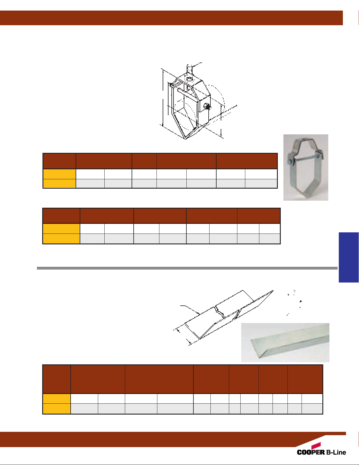
Fig. B3106 - Vee Bottom Clevis Hanger (TOLCO Fig. 1V)
Pipe Hangers
Size Range:1/2” (15mm) to 4”
(100mm)
pipe
Material: Steel
Function: Recommended for the suspension of
flexible plastic pipe. Use with B3106V support trough
for plastic pipe.
Approvals: Complies with Manufacturers
Standardization Society
ANSI/MSS SP-69 & SP-58
Type 1.
Standard Finish: Plain & Electro-Galvanized.
Contact Cooper B-Line for alternative finishes and
materials.
Order By: Figure number and finish.
Pipe Size Rod Size B C
Part No.
B3106-2
B3106-4
in. (mm) A in. (mm) in. (mm)
1
/2" to 2" (15 to 50)3/8"-16 515/16" (150.8) 41/16" (103.2)
21/2
" to
4" (65 to 100)1/2"-13 93/8" (238.1) 6" (152.4)
Rod Take-Out D Adjustment E Design Load Approx Wt./100
Part No.
in. (mm) in. (mm) Lbs. (kN) Lbs. (kg)
A
(Rod Size)
Hanger Rod Not
Included
B
D
C
Center of pipe to top of hanger.
Center of pipe to bottom of hanger rod.
Minimum thread length of hanger rod.
B
Overall Height
C
D
Rod Take-Out
E
B3106-2 35/16" (84.1) 15/8" (41.3) 150 (.67) 60 (27.2)
B3106-4 413/16" (122.2) 23/16" (55.6) 150 (.67) 143 (64.8)
Fig. B3106V - Plastic Pipe Support Channel (TOLCO Fig. 1VT)
Size Range:1/2” (15mm) to 4”
Material: Steel
Function: Designed for use with B3106 as a
support for plastic or other flexible pipe systems.
Standard Finish: Pre-Galvanized. Contact
Cooper B-Line for alternative finishes and
materials.
Order By: Figure number and finish.
Part No. in. (mm) in. (mm) in. (mm) Ft. (M) Lbs. (kN) Lbs. (kg)
B3106V-2
B3106V-4
1
/2"to
21/2"to
(100mm)
pipe
T x L
Steel Size
B
Maximum
For Nominal Steel Size Hanger Design Approx.
Pipe Sizes T x L B Spacing Load Wt./100
2" (15 to 50)
4" (65 to 100)
18 Ga. x 96" (1.2 x 2438.4)
18 Ga. x 120" (1.2 x 3048.0)
19/16
" (39.7) 8 (2.44) 150 (.67) 449 (203.6)
31/8
" (79.4) 10 (3.05) 150 (.67) 1123 (509.4)
Pipe Hangers
All dimensions in charts and on drawings are in inches. Dimensions shown in parentheses are in millimeters unless otherwise specified.
55
Page 58

Pipe Hangers
Fig. B3104 - Light-Duty Clevis Hanger
Fig. B3104F - Light-Duty Clevis Hanger - Felt Lined
Fig. B3104C - Light-Duty Clevis Hanger - PVC Coated
Size Range:1/2” (15mm) to 4”
Material: Steel
Function: Recommended for the suspension of light stationary
pipe allowing for vertical adjustment.
Approvals: Underwriter's Laboratories Listed in the USA (UL)
and Canada (cUL) for sizes
Conforms to Federal Specification WW-H-171E & A-A-1192A,
Type 12 and Manufacturers Standardization Society ANSI/MSS
SP-69 & SP-58, Type 1.
Standard Finish: Plain, Electro-Galvanized,
DURA-GREEN
or
™
Order By: Figure number and finish.
(100mm)
3
/4” (20mm) thru 4” (100mm).
pipe
(Rod Size)
Hanger Rod Not
Included
E
D
*Slide-Rite™ Clevis Hanger
design for sizes 2, 3 & 4.
Pat. No. 5,848,770
5,924,655
A
Bottom of pipe to top of hanger.
Center of pipe to top of hanger.
Center of pipe to bottom of
C
B
Minimum thread length of
Top of cross bolt to bottom of hanger rod
B
C
D
Rod Take-Out
hanger rod.
E
hanger rod.
F
Adjustment
nut inside the hanger.
B3104-1/2
B3104-3/4
Pipe Hangers
B3104-1 1" (25)
B3104-11/4 11/4" (32)
B3104-11/2 11/2" (40)
B3104-2 * 2" (50)
B3104-21/2 21/2" (65)
B3104-3 * 3" (80)
B3104-31/2 31/2" (90)
B3104-4 * 4" (100)1/2"-13 73/4"
B3104-1/2
B3104-3/4 1" (25.4) 21/2" (63.5)
B3104-1 13/8" (34.9) 21/2" (63.5)
B3104-11/4 13/4" (44.4) 21/2" (63.5)
B3104-11/2 2" (50.8) 21/2" (63.5) 1" (25.4) 250 (1.11) 30 (13.6)
B3104-2 * 215/16" (74.6) 21/2" (63.5) 13/4" (44.4) 250 (1.11) 35 (15.9)
B3104-21/2 37/16" (87.3) 21/2" (63.5) 2" (50.8) 350 (1.55) 82 (37.2)
B3104-3 * 33/4" (95.2) 21/2" (63.5) 2" (50.8) 350 (1.55) 91 (41.3)
B3104-31/2 4" (101.6) 21/2" (63.5) 2" (50.8) 350 (1.55) 98 (44.4)
B3104-4 * 49/16" (115.9) 21/2" (63.5) 23/16" (55.6) 400 (1.78) 132 (59.9)
Pipe Size Rod Size B C
Part No. in. (mm) A in. (mm) in. (mm)
1
/2" (15)
3
/4" (20)
3
/8"-16 115/16" (49.2) 11/2" (38.1)
3
/8"-16 25/16" (58.7) 13/4" (44.4)
3
/8"-16 23/4" (69.8) 21/16" (52.4)
3
/8"-16 35/16" (84.1) 27/16" (61.9)
3
/8"-16 35/8" (92.1) 25/8" (66.7)
3
/8"-16 413/16" (122.2) 35/8" (92.1)
1
/2"-13 513/16" (147.6) 45/16" (109.5)
1
/2"-13 67/16" (163.5) 45/8" (117.5)
1
/2"-13 615/16" (176.2) 415/16" (125.4)
(196.8)
51/2" (139.7)
Rod Take-Out D E Adjustment F Design Load Approx. Wt./100
Part No. in. (mm) in. (mm) in. (mm) Lbs. (kN) Lbs. (kg)
13
/16" (20.6) 21/2" (63.5)
7
/16" (11.1) 150 (.67) 13 (5.9)
7
/16" (11.1) 250 (1.11) 22 (10.0)
9
/16" (14.3) 250 (1.11) 24 (10.9)
13
/16" (20.6) 250 (1.11) 29 (13.1)
B3104C
B3104F
All dimensions in charts and on drawings are in inches. Dimensions shown in parentheses are in millimeters unless otherwise specified.
56
Page 59
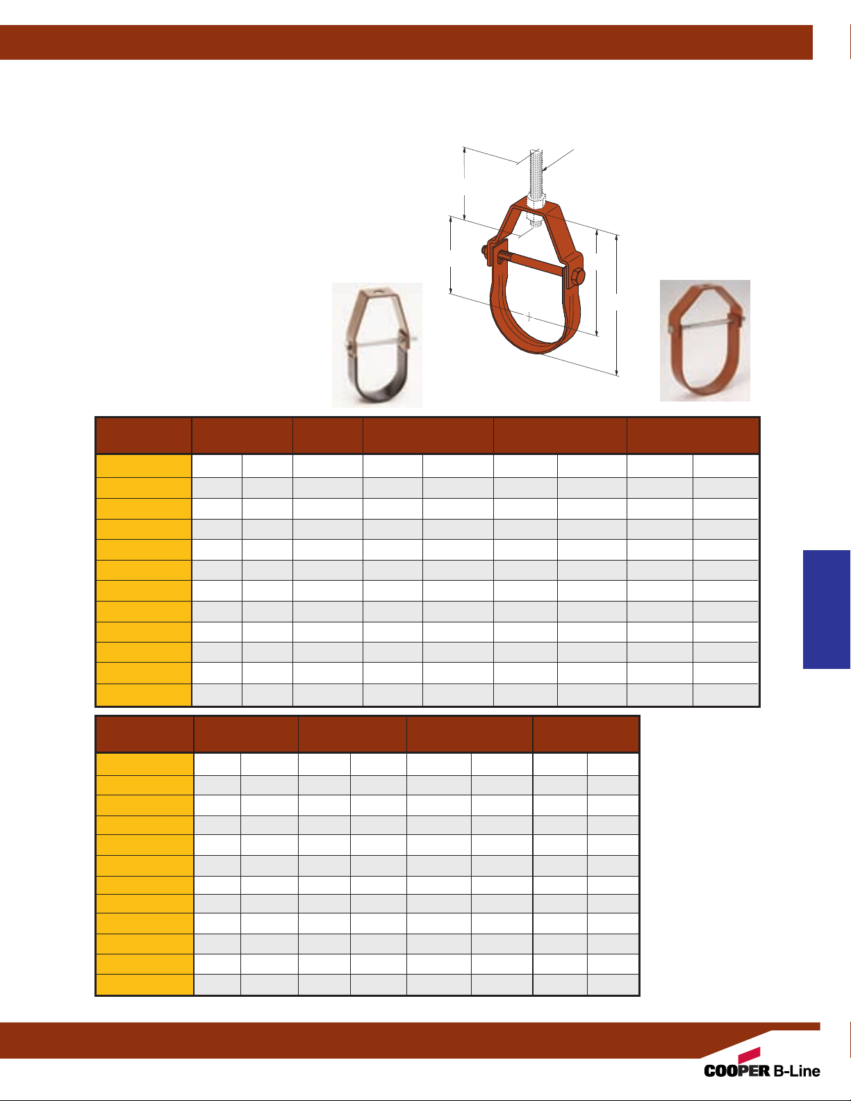
Pipe Hangers
Fig. B3104CT - Clevis Hanger (TOLCO Fig. 81)
Fig. B3104CTC - Clevis Hanger - PVC Coated (TOLCO Fig. 81PVC)
Size Range:1/2” (15mm) to 6” (150mm) copper tubing
Material: Steel
Function: Recommended for the suspension of
non- insulated stationary copper tubing lines.
vailable with plastic coating to provide additional
A
separation between tubing and hanger.
Approvals:
Conforms to Federal Specification
WW-H-171E & A-A-1192A, Type 12 and Manufacturers
Standardization Society ANSI/MSS SP-69 & SP-58,
Type 1.
Standard Finish: DURA-COPPER
Order By:
Figure
number and finish.
™
B3104CTC
Tubing Size Rod Size B C Rod Take-Out D
Part No.
B3104CT-1/2
B3104CT-3/4
B3104CT-1 1" (25)
B3104CT-11/4 11/4" (32)
B3104CT-11/2 11/2" (40)
B3104CT-2 2" (50)
B3104CT-21/2 21/2" (65)
B3104CT-3 3" (80)
B3104CT-31/2 31/2" (90)
B3104CT-4 4" (100)
B3104CT-5 5" (125)
B3104CT-6 6" (150)
in. (mm) A in. (mm) in. (mm) in. (mm)
1
/2" (15)
3
/4" (20)
3
/8"-16 21/4" (57.1) 115/16" (49.2) 11/8" (28.6)
3
/8"-16 115/16" (49.2) 11/2" (38.1) 11/8" (28.6)
3
/8"-16 25/16" (58.7) 13/4" (44.4) 15/16" (33.3)
3
/8"-16 23/4" (69.8) 21/16" (52.4) 19/16" (39.7)
3
/8"-16 35/16" (84.1) 27/16" (61.9) 21/16" (52.4)
3
/8"-16 41/2" (114.3) 37/16" (87.3) 33/8" (85.7)
1
/2"-13 511/16" (144.5) 41/2" (114.3) 315/16" (100.0)
1
/2"-13 53/16" (131.8) 35/8" (92.1) 4" (101.6)
1
/2"-13 61/2" (165.1) 49/16" (115.9) 41/8" (104.8)
1
/2"-13 73/8" (187.3) 35/16"
1
/2"-13 9" (228.6) 67/16" (163.5) 53/4" (146.0)
5
/8"-11 105/16" (261.9) 71/4"
E
D
A
(Rod Size)
Hanger Rod Not
Included
C
B
B3104CT
(134.9) 4
(184.1) 6
Bottom of pipe to top of hanger.
Center of pipe to top of hanger.
Center of pipe to bottom
Minimum thread length
Top of cross bolt to bottom of
hanger rod nut inside the hanger.
3
1
B
C
D
Rod Take-Out
of hanger rod.
E
of hanger rod.
F
Adjustment
/8" (111.1)
/2" (165.1)
Pipe Hangers
E Adjustment F Design Load Approx. Wt./100
Part No.
B3104CT-1/2 21/2" (63.5)
B3104CT-3/4 21/2" (63.5)
B3104CT-1 21/2" (63.5)
B3104CT-11/4 21/2" (63.5)
B3104CT-11/2 21/2" (63.5)
in. (mm) in. (mm) Lbs. (kN) Lbs. (kg)
3
/8" (9.5) 150 (.67) 12 (5.4)
7
/16" (11.1) 250 (1.11) 12 (5.4)
9
/16" (14.3) 250 (1.11) 22 (10.0)
9
/16" (14.3) 250 (1.11) 24 (10.9)
15
/16" (23.8) 250 (1.11) 30 (13.6)
B3104CT-2 21/2" (63.5) 13/4" (44.4) 250 (1.11) 35 (15.9)
B3104CT-21/2 21/2" (63.5) 21/8" (54.0) 350 (1.55) 80 (36.3)
B3104CT-3 21/2" (63.5) 21/16" (52.4) 350 (1.55) 88 (39.9)
B3104CT-31/2 21/2" (63.5) 21/8" (54.0) 350 (1.55) 94 (42.6)
B3104CT-4 21/2" (63.5) 21/8" (54.0) 400 (1.78) 116 (52.6)
B3104CT-5 21/2" (63.5) 21/2" (63.5) 550 (2.44) 208 (94.3)
B3104CT-6 21/2" (63.5) 3" (76.2) 550 (2.44) 247 (112.0)
All dimensions in charts and on drawings are in inches. Dimensions shown in parentheses are in millimeters unless otherwise specified.
57
Page 60
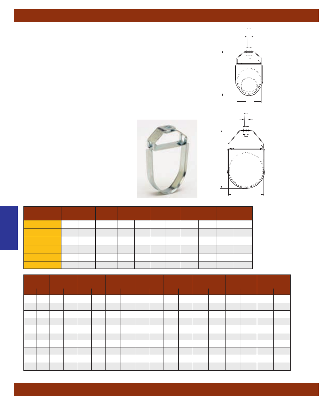
Pipe Hangers
Fig. 1U - Ultra Clevis Hanger
Size Range:1/2” (15mm) to 4”
Material: Pre-Galvanized Steel
Function: Recommended for the suspension of piping systems.
Features:
• Fast, easy, snap open and closed installation
• Strong lightweight design
• Flared edges ease installation for all pipe types and protect
CPVC plastic pipe from abrasion
• Clevis bottom locks in place to prevent swaying
Approvals: Conforms to Manufacturers Standardization Society ANSI/MSS
SP-69 & SP-58,
Type 1.
Maximum Temperature: 650°F
Standard Finish: Pre-Galvanized
Order By: Figure number and finish.
Patent Pending
(100mm)
(343°C).
pipe
1
/2” thru 2”
B
21/2” thru 4”
B
A
(Rod Size)
Hanger Rod Not
Included
C
A
(Rod Size)
Hanger Rod Not
Included
C
Pipe Hangers
Part No. in. (mm) A in. (mm) in. (mm) lbs. (mN) lbs. (kg)
1U-1/2-1
Pipe Size Rod Size B C Max. Rec. Load Approx. Wt./100
1
/2" - 1" (15 - 25)3/8"-16 31/16" (77.8) 19/16" (39.7) 200 (0.89) 8 (3.6)
1U-11/4-2 11/4" - 2" (32 - 50)3/8"-16 41/2" (114.3) 27/8" (73.0) 250 (1.11) 18 (8.1)
1U-21/2 21/2" (65)
1U-3 3" (80)
1U-31/2 31/2" (90)
1U-4 4" (100)
1
/2"-13 53/8" (136.5) 215/16" (74.7) 350 (1.55) 36 (16.3)
1
/2"-13 63/16" (157.2) 39/16" (90.5) 350 (1.55) 44 (19.9)
1
/2"-13 71/4" (184.1) 41/16" (103.2) 350 (1.55) 50 (22.7)
1
/2"-13 75/8" (193.7) 49/16" (115.9) 400 (1.78) 55 (24.4)
Pipe Max. Spacing Sch. 40 Sch. 80 Sch. 40 Sch. 80 Sch.40 Total Sch. 80 Total 1U Load
Size Per MSS Pipe Pipe Water Water Supported Load Supported Load Rating w/SF 3.5
in. (mm) ft. (m) lbs./ft. (kg/m) lbs./ft. (kg/m) lbs./ft. (kg/m) lbs./ft. (kg/m) lbs. (kg) lbs. (kg) lbs. (kN)
1
/2" (15) 7 (2.13) 0.85 (1.26) 1.09 (1.62) 0.13 (0.19) 0.10 (0.15) 6.87 (3.11) 8.32 (3.77) 200 (0.89)
3
/4" (20) 7 (2.13) 1.13 (1.68) 1.47 (2.19) 0.23 (0.34) 0.19 (0.28) 9.52 (4.32) 11.61 (5.26) 200 (0.8)
1" (25) 7 (2.13) 1.68 (2.50) 2.17 (3.23) 0.37 (0.55) 0.31 (0.46) 14.36 (6.51) 17.37 (7.88) 200 (0.89)
11/4" (32) 7 (2.13) 2.27 (3.38) 3.00 (4.46) 0.65 (0.97) 0.56 (0.83) 20.43 (9.27) 24.86 (11.27) 250 (1.11)
11/2" (40) 9 (2.74) 2.72 (4.05) 3.63 (5.40) 0.88 (1.31) 0.77 (1.14) 32.39 (14.69) 39.56 (17.94) 250 (1.11)
2" (50) 10 (3.05) 3.65 (5.43) 5.02 (7.47) 1.45 (2.16) 1.28 (1.90) 51.04 (23.15) 63.01 (28.58) 250 (1.11)
21/2" (65) 11 (3.35) 5.79 (8.61) 7.66 (11.40) 2.07 (3.08) 1.83 (2.72) 86.48 (39.23) 104.43 (47.37) 350 (1.55)
3" (80) 12 (3.65) 7.57 (11.26) 10.25 (15.25) 3.20 (4.76) 2.86 (4.25) 129.24 (58.62) 157.32 (71.36) 350 (1.55)
31/2" (90) 13 (3.96) 9.11 (13.56) 12.51 (18.61) 4.28 (7.37) 3.85 (5.73) 174.07 (78.96) 212.68 (96.47) 350 (1.55)
4" (100) 14 (4.29) 10.79 (16.06) 14.98 (22.29) 5.51 (8.20) 4.98 (7.41) 228.20 (103.51) 279.44 (126.75) 400 (1.78)
All dimensions in charts and on drawings are in inches. Dimensions shown in parentheses are in millimeters unless otherwise specified.
58
Page 61
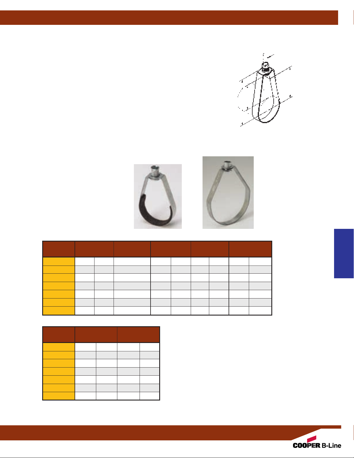
B3170 - Adjustable Band Hanger (TOLCO Fig. 2)
B3170F - Adjustable Band Hanger Felt Lined (TOLCO Fig. 2F)
Size Range: 21/2” (65mm) thru 8” (200mm) pipe
Material: Steel
vailable in stainless steel
A
Function: Recommended for the suspension of noninsulated pipe or insulated pipe with B3151 shield.
Approvals: Conforms to Federal Specification
-H-171E & A-A-1192A, Type 10 and Manufacturers
WW
Standardization Society ANSI/MSS SP-69 & SP-58,
Type 10.
Standard Finish: Pre-Galvanized
Order By: Figure number and finish.
Center of pipe to top of
knurled hanger rod nut.
Rod Take-Out
Center of pipe to bottom
of hanger rod.
Top of pipe to bottom of
hanger rod nut.
Pipe Hangers
A
(Rod Size)
Hanger Rod Not
B
C
D
D
B
Included
C
Part No. Pipe Size A
Nominal Rod Size B C D
B3170-21/2 21/2" (65)
B3170-3 3" (75)
B3170-31/2 31/2" (90)
B3170-4 4" (100)
B3170-5 5" (125)
B3170-6 6" (150)
B3170-8 8" (200)
1
/2"-13 4" (101.6) 25/8" (66.7) 19/16" (39.7)
1
/2"-13 41/2" (114.3) 31/8" (79.4) 15/8" (41.3)
1
/2"-13 415/16" (125.4) 39/16" (90.5) 113/16" (46.0)
5
/8"-11 53/16" (131.8) 35/8" (92.1) 15/8" (41.3)
5
/8"-11 525/32" (146.8) 41/8" (104.8) 15/8" (41.3)
3
/4"-10 7" (177.8) 51/16" (128.6) 2" (50.8)
3
/4"-10 8" (203.2) 65/16" (160.3) 21/2" (63.5)
Max. Rec. Load Approx. Wt./100
Part No.
lbs. (kN) lbs. (kg)
B3170-21/2 300 (1.33) 29 (13.1)
B3170-3 300 (1.33) 34 (15.4)
B3170-31/2 300 (1.33) 42 (19.0)
B3170-4 475 (2.11) 54 (24.5)
B3170-5 475 (2.11) 97 (44.0)
B3170-6 950 (4.22) 113 (51.2)
B3170-6 950 (4.22) 140 (63.5)
B3170B3170F
in. (mm) in. (mm) in. (mm)
Pipe Hangers
All dimensions in charts and on drawings are in inches. Dimensions shown in parentheses are in millimeters unless otherwise specified.
59
Page 62
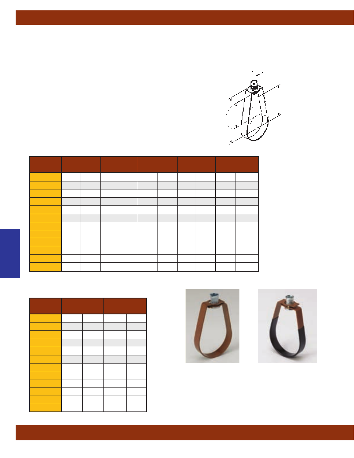
Pipe Hangers
B3170CT - Adjustable Swivel Hanger for Copper Tubing (TOLCO Fig. 202)
B3170CTC - Adjustable Swivel Hanger for Copper Tubing - Plastic Coated
Size Range:1/2” (15mm) thru 6” (150mm) copper tubing
Material: Steel
Function: Recommended for the suspension of
copper tubing, allowing for vertical adjustment.
vailable with plastic coating to provide additional
(A
separation between tubing and hanger.)
Approvals: Conforms to Federal Specification
WW-H-171E & A-A-1192A, Type 10 and Manufacturers
Standardization Society ANSI/MSS SP-69 & SP-58,
Type 10.
Standard Finish: DURA-COPPER
™
Order By: Figure number and finish.
Nominal Rod Size B C D
Part No. Pipe Size A
B3170CT-1/2
B3170CT-3/4
B3170CT-1 1" (25)
B3170CT-11/4 11/4" (32)
B3170CT-11/2 11/2" (40)
B3170CT-2 2" (50)
B3170CT-21/2 21/2" (65)
B3170CT-3 3" (75)
Pipe Hangers
B3170CT-31/2 31/2" (90)
B3170CT-4 4" (100)
B3170CT-5 5" (125)
B3170CT-6 6" (150)
1
/2" (15)
3
/4" (20)
3
/8"-16 21/16" (52.4) 11/8" (28.6)
3
/8"-16 25/16" (58.7) 15/16" (33.3) 11/32" (26.2)
3
/8"-16 21/2" (63.5) 19/16" (39.7) 15/32" (29.3)
3
/8"-16 21/2" (63.5) 19/16" (39.7) 1" (25.4)
3
/8"-16 215/16" (74.6) 2" (50.8) 15/16" (33.3)
3
/8"-16 31/8" (79.4) 21/8" (54.0) 13/16" (30.2)
1
/2"-13 41/16" (103.2) 29/16" (65.1) 13/8" (34.9)
1
/2"-13 315/16" (100.0) 33/4" (95.2) 11/4" (31.7)
1
/2"-13 47/16" (112.7) 31/4" (82.5) 11/2" (38.1)
1
/2"-13 411/16" (119.1) 39/16" (89.6) 19/16" (39.7)
1
/2"-13 515/16" (150.8) 45/16" (109.5) 125/32" (45.2)
1
/2"-13 611/16" (169.9) 53/16" (131.8) 21/8" (54.0)
Center of pipe to top of
knurled hanger rod nut.
Center of pipe to bottom
Top of pipe to bottom of
in. (mm) in. (mm) in. (mm)
B
C
Rod Take-Out
of hanger rod.
D
hanger rod nut.
D
B
31
/32" (24.6)
A
(Rod Size)
Hanger Rod Not
Included
C
Part No.
lbs. (kN) lbs. (kg)
B3170CT-1/2 180 (0.80) 8 (6.6)
B3170CT-3/4 180 (0.80) 10 (4.5)
B3170CT-1 180 (0.80) 10 (4.5)
B3170CT-11/4 180 (0.80) 12 (5.4)
B3170CT-11/2 180 (0.80) 12 (5.4)
B3170CT-2 180 (0.80) 12 (5.4)
Max. Rec. Load Approx. Wt./100
B3170CT-21/2 200 (0.89) 31 (24.0)
B3170CT
B3170CT-3 250 (1.11) 33 (14.9)
B3170CT-31/2 300 (1.33) 39 (17.2)
B3170CT-4 360 (1.60) 40 (18.1)
B3170CT-5 480 (2.13) 95 (43.1)
B3170CT-6 630 (2.80) 118 (53.5)
All dimensions in charts and on drawings are in inches. Dimensions shown in parentheses are in millimeters unless otherwise specified.
60
B3170CTC
Page 63

Pipe Hangers
Fig. 200 - “Trimline” Adjustable Band Hanger (Cooper B-Line Fig. B3170NF)
Fig. 200F - “Trimline” Adjustable Band Hanger with Felt Lining (Cooper B-Line Fig. B3170NFF)
Fig. 200C - “Trimline” Adjustable Band Hanger with Plastic Coated (Cooper B-Line Fig. B3170NFC)
Size Range:
1
Fig. 200 -
/2” (15mm) thru 8” (200mm) pipe
Material: Steel, Pre-Galvanized to G90 specifications
Function: For fire sprinkler and other general piping purposes. Knurled
swivel nut design permits hanger adjustment after installation.
Features:
1
•(
/2” (15mm) thru 2” (50mm)) Flared edges ease installation for all pipe
types and protect CPVC plastic pipe from abrasion. Captured design
keeps adjusting nut from separating with hanger. Hanger is easily
installed around pipe.
1
/2” (65mm) thru 8” (200mm)) Spring tension on nut holds it securely in
•(2
hanger before installation. Adjusting nut is easily removed.
1
Approvals: Underwriters Laboratories listed (
/2” (15mm) thru 8” (200mm))
in the USA (UL) and Canada (cUL) for steel and CPVC plastic pipe and
3
Factory Mutual Engineering
Approved (
/4” (20mm) thru 8” (200mm)).
Conforms to Federal Specifications WW-H-171E & A-A-1192A, Type 10
and Manufacturers Standardization Society ANSI/MSS SP-69 & SP-58,
Type 10.
Maximum Temperature: 650°F
(343°C)
Finish: Pre-Galvanized. Stainless Steel
materials will be supplied with (2) hex nuts
in place of a knurl nub.
Order By: Figure number and pipe size
™
Fig. 200-1 to 200-2
B
A
Fig. 200-1/2. 200-3/4
1
Fig. 200-2
/2 to 200-8
** Note: For metric hanger rod sizes add the
metric rod size to the figure number
1
Example: 200M8-1
/2 or 200M10-11/2
.
Fig. 200C
Fig. 200F
Pipe Size Rod Size A B Max. Rec. Load Approx. Wt./100
Part No.
200-1/2
200-3/4
in. (mm) in. mm** in. (mm) in. (mm) lbs. (kN) lbs. (kg)
1
/2" (15)3/8"-16 M8 or M10 31/8" (79.4) 25/8" (66.7) 400 (1.78) 11 (5.0)
3
/4" (20)3/8"-16 M8 or M10 31/8" (79.4) 21/2" (63.5) 400 (1.78) 11 (5.0)
200-1 1" (25)3/8"-16 M8 or M10 33/8" (85.7) 25/8" (66.7) 400 (1.78) 12 (5.5)
200-11/4 11/4" (32)3/8"-16 M8 or M10 33/4" (94.0) 27/8" (73.0) 400 (1.78) 13 (5.9)
200-11/2 11/2" (40)3/8"-16 M8 or M10 37/8" (98.4) 27/8" (73.0) 400 (1.78) 14 (6.4)
200-2 2" (50)3/8"-16 M8 or M10 41/2" (114.3) 3" (76.3) 400 (1.78) 15 (6.9)
200-21/2 21/2" (65)3/8"-16 M10 55/8" (142.9) 41/8" (104.7) 600 (2.67) 27 (12.3)
200-3 3" (75)3/8"-16 M10 57/8" (149.1) 4" (101.6) 600 (2.67) 29 (13.3)
200-31/2 31/2" (90)3/8"-16 M10 73/8" (187.3) 51/4" (133.3) 600 (2.67) 34 (15.6)
200-4 4" (100)3/8"-16 M10 73/8" (187.3) 5" (127.0) 1000 (4.45) 35 (16.0)
200-5 5" (125)1/2"-13 M12 91/8" (231.8) 61/4" (158.7) 1250 (5.56) 66 (30.2)
200-6 6" (150)1/2"-13 M12 101/8" (257.2) 63/4" (171.4) 1250 (5.56) 73 (33.4)
200-8 8" (200)1/2"-13 M12 131/8" (333.4) 83/4" (222.2) 1250 (5.56) 136 (62.3)
All dimensions in charts and on drawings are in inches. Dimensions shown in parentheses are in millimeters unless otherwise specified.
Fig. 200
Pipe Hangers
61
Page 64

Pipe Hangers
Fig. 200H - Heavy Duty Band Hanger (For Trapeze)
Size Range: 2” (50mm) thru 4” (100mm) trapeze pipe size.
Material: Steel — Pre-Galvanized to G40 Spec
Function: Designed primarily to support substantially heavier loads
than is normally intended for the nominal hanger size. Used
extensively to support trapeze installations and the increased loads
from both above and below the trapeze assembly
Features: Furnished with
3
/8"-16 or 1/2"-13 adjusting threaded ring nut.
Approvals: Underwriters Laboratories listed in the USA (UL) and
Canada** (cUL). Conforms to Federal Specification WW-H-171E &
A-A-1
192A, Type 10 and Manufacturers Standardization Society
ANSI/MSS SP-69 & SP-58, Type 10.
Maximum Temperature: 650°F
(343°C)
Finish: Pre-Galvanized
Order By: Figure number, pipe size and rod size.
Important Design Note. Because of the increased loads applied to
the trapeze assembly
, both the upper trapeze supports as well as the
lower hanging unit must be able to hold the maximum loads intended.
.
™
B
A
Pipe Hangers
Pipe Size Rod Size A B Max. Rec. Load Approx. Wt./100
Part No.
200H-2-3/8 2" (50)
200H-2-1/2 2" (50)
200H-21/2-3/8 21/2" (65)
200H-21/2-1/2 21/2" (65)
200H-3-3/8 3" (75)
200H-3-1/2 3" (75)
200H-4-3/8 4" (100)
200H-4-1/2 4" (100)
* Select trapeze pipe size based on section modulus required for span of trapeze per information provided in
NFPA 13 (2002) Table 9.1.1.6.1 (a and b).
** All sizes are UL Listed to support up to 8" pipe at max spacing per NFPA 13.
(150mm) and 8” (200mm) trapeze pipe, consult factory.
For 6”
in. (mm) in. (mm) in. (mm) lbs. (kN) lbs. (kg)
3
/8"-16 49/16" (115.9) 37/32" (81.7) 1200 (5.34) 48 (21.8)
1
/2"-13 423/32" (119.8) 33/8" (85.7) 1200 (5.34) 45 (20.4)
3
/8"-16 55/16" (134.9) 323/32" (94.4) 1200 (5.34) 59 (26.7)
1
/2"-13 515/32" (138.9) 37/8" (98.3) 1200 (5.34) 56 (25.4)
3
/8"-16 53/4" (146.0) 327/32" (97.6) 1200 (5.34) 63 (28.6)
1
/2"-13 57/8" (148.1) 331/32" (100.8) 1200 (5.34) 60 (27.2)
3
/8"-16 67/8" (174.6) 47/16" (112.7) 1200 (5.34) 76 (34.5)
1
/2"-13 71/32" (178.6) 419/32" (1116.7) 1200 (5.34) 73 (33.1)
All dimensions in charts and on drawings are in inches. Dimensions shown in parentheses are in millimeters unless otherwise specified.
62
Page 65

Fig. B3198H - Hinged Extension Split Pipe Clamp (TOLCO Fig. 302)
Size Range:3/8” (10mm) to 3”
Material: Malleable Iron
Function: Designed for suspending non-insulated pipe horizontally or vertically.
Approvals: Conforms to Federal Specification WW-H-171E & A-A-1192A, Type 25
and Manufacturers Standardization Society ANSI/MSS SP-69 & SP-58,
Standard Finish: Plain or Electro-Galvanized
Order By: Figure number and finish.
Pipe Size Rod Size C Design Load Approx. Wt./100
Part No.
B3198H-3/8
B3198H-1/2
B3198H-3/4
in. (mm) A in. (mm) Lbs. kN Lbs. kg
3
/8" (10)
1
/2" (15)
3
/4" (20)
B3198H-1 1" (25)
B3198H-11/4 11/4" (32)
B3198H-11/2 11/2" (40)
B3198H-2 2" (50)
B3198H-21/2 21/2" (65)
B3198H-3 3" (80)
(80mm)
pipe
Type 12.
3
/8"-16
3
/8"-16 11/16" (27.0) 180 (.80) 12 (5.4)
3
/8"-16 17/32" (30.9) 180 (.80) 12 (5.4)
3
/8"-16 111/32" (34.1) 180 (.80) 13 (5.9)
3
/8"-16 119/32" (39.7) 180 (.80) 18 (8.1)
3
/8"-16 123/32" (43.6) 180 (.80) 21 (9.5)
3
/8"-16 2" (50.8) 180 (.80) 44 (19.9)
1
/2"-13 211/32" (59.5) 300 (1.33) 73 (33.1)
1
/2"-13 223/32" (69.0) 300 (1.33) 95 (43.1)
31
/32" (24.6) 180 (.80) 9 (4.1)
Pipe Hangers
A
(Rod Size)
Hanger Rod Not
C
Included
Fig. B3198R - Extension Split Pipe Clamp
Size Range:3/8” (10mm) to 4”
Material: Malleable Iron
Function: Designed for suspending non-insulated pipe horizontally or vertically.
Approvals: Conforms to Federal Specification WW-H-171E &
and Manufacturers Standardization Society ANSI/MSS SP-69 & SP-58, Type 12.
Standard Finish: Plain or Electro-Galvanized. Contact Cooper B-Line for alternative
finishes and materials.
Order By: Figure number and finish.
Part No. Pipe Size Thread Size C Design Load Approx. Wt./100
Rod Thread
B3198R-3/8
B3198R-1/2
B3198R-3/4
B3198R-1 1" (25)
B3198R-11/4 11/4" (32)
B3198R-11/2 11/2" (40)
B3198R-2 2" (50)
B3198R-21/2 21/2" (65)
B3198R-3 3" (80)
B3198R-4 4" (100)
(100mm)
pipe
A-A-1192A, Type 25
Rod
in. (mm) A in. (mm) Lbs. (kN) Lbs. (kg)
3
/8" (10)
1
/2" (15)
3
/4" (20)
3
/8"-16
3
/8"-16 11/16" (27.0) 180 (.80) 16 (7.2)
3
/8"-16 17/32" (30.9) 180 (.80) 18 (8.1)
3
/8"-16 111/32" (34.1) 180 (.80) 24 (10.9)
3
/8"-16 119/32" (39.7) 180 (.80) 29 (13.1)
3
/8"-16 123/32" (43.6) 180 (.80) 32 (14.5)
3
/8"-16 2" (50.8) 180 (.80) 39 (17.7)
1
/2"-13 211/32" (59.5) 300 (1.33) 115 (52.1)
1
/2"-13 223/32" (69.0) 300 (1.33) 140 (63.5)
1
/2"-13 311/32" (84.9) 300 (1.33) 160 (72.6)
31
/32" (24.6) 180 (.80) 12 (5.4)
A
(Thread Size)
Hanger Rod Not
C
Included
Pipe Hangers
All dimensions in charts and on drawings are in inches. Dimensions shown in parentheses are in millimeters unless otherwise specified.
63
Page 66

Pipe Hangers
Fig. B3198HCT - Hinged Extension Split Pipe Clamp (TOLCO Fig. 301CT)
Size Range:1/2” (15mm) to 2”
(50mm)
copper tubing
Material: Malleable Iron
Function: A rigid support to suspend tubing
horizontally or vertically
.
Approvals: Conforms to Federal Specification
WW
-H-171E & A-A-1192A, Type 25 and Manufacturers
Standardization Society ANSI/MSS SP-69 & SP-58,
Type 12.
Standard Finish: DURA-COPPER
™
Order By: Figure number and finish.
Tubing Size Rod Size C Design Load Approx. Wt./100
Part No. in. (mm) A in. (mm)
B3198HCT-1/2
B3198HCT-3/4
1
/2" (15)
3
/4" (20)
B3198HCT-1 1" (25)
B3198HCT-11/4 11/4" (32)
B3198HCT-11/2 11/2" (40)
B3198HCT-2 2" (50)
3
/8"-16
3
/8"-16
3
/8"-16
3
/8"-16 11/8" (28.6) 180 (.80) 14 (6.3)
3
/8"-16 19/16" (39.7) 180 (.80) 18 (8.1)
3
/8"-16 17/8" (47.6) 180 (.80) 23 (10.4)
C
Lbs. (kN) Lbs. (kg)
5
/8" (15.9) 180 (.80) 8 (3.6)
13
/16" (20.6) 180 (.80) 10 (4.5)
15
/16" (23.8) 180 (.80) 10 (4.5)
A
(Rod Size)
Hanger Rod
Not Included
Fig. B3198RCT - Extension Split Pipe Clamp
Pipe Hangers
Size Range:1/2” (15mm) to 2”
Material: Malleable Iron
Function: A rigid support to suspend tubing horizontally or
vertically
.
Approvals: Conforms to Federal Specification WW-H-171E &
A-A-1192A,
Type 25 and Manufacturers Standardization
Society ANSI/MSS SP-69 & SP-58, Type 12.
Standard Finish: DURA-COPPER
Order By: Figure number and finish.
Part No. in. (mm) A in. (mm) Lbs. (kN) Lbs. (kg)
B3198RCT-3/8
B3198RCT-1/2
B3198RCT-3/4
B3198RCT-1 1" (25)
B3198RCT-11/4 11/4" (32)
B3198RCT-11/2 11/2" (40)
B3198RCT-2 2" (50)
(50mm)
copper tubing
™
Tubing Size Rod Size C Design Load Approx. Wt./100
3
/8" (10)
1
/2" (15)
3
/4" (20)
3
/8"-16
3
/8"-16 111/16" (17.5) 180 (.80) 12 (5.4)
3
/8"-16
3
/8"-16 11/16" (27.0) 180 (.80) 17 (7.7)
3
/8"-16 11/8" (28.6) 180 (.80) 17 (7.7)
3
/8"-16 15/16" (33.3) 180 (.80) 22 (10.0)
3
/8"-16 11/2" (38.1) 180 (.80) 26 (11.8)
11
/16" (17.5) 180 (.80) 12 (5.4)
7
/8" (22.2) 180 (.80) 14 (6.3)
A
(Thread Size)
Hanger Rod
C
Not Included
All dimensions in charts and on drawings are in inches. Dimensions shown in parentheses are in millimeters unless otherwise specified.
64
Page 67
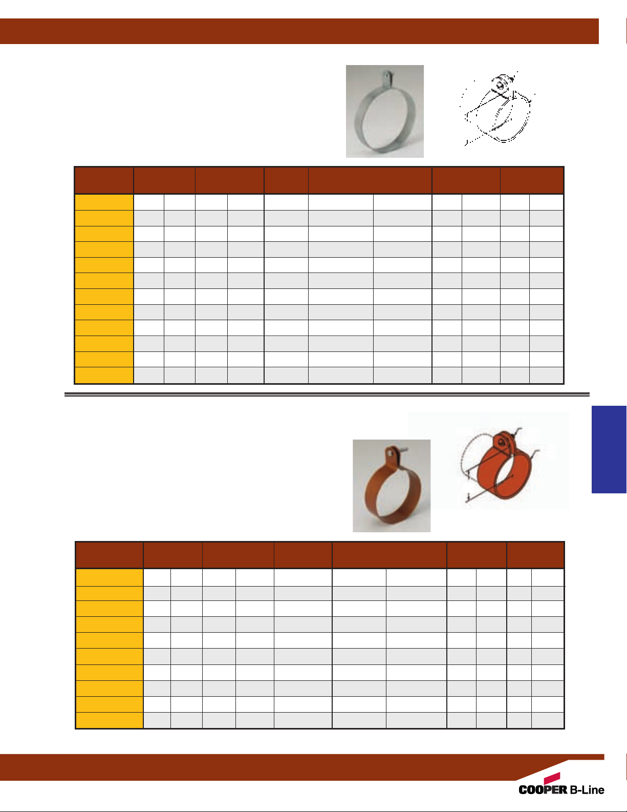
Pipe Hangers
Fig. B3175 - Ring and Bolt Hanger
Size Range:1/2” (15mm) to 6”
(150mm)
pipe
Bolt and Nut Included
Material: Pre-Galvanized Steel
Function: Designed for suspending light-weight non-insulated pipe.
(Use with B3222 eye socket or B3224 hanger adjuster).
Standard Finish: Pre-Galvanized
C
Order By: Figure number and finish.
Pipe Size C Steel Size Design Load
Part No. in. (mm) in. (mm) Bolt Size in. (mm) Lbs. (kN) Lbs. (kg)
B3175-1/2
B3175-3/4
1
/2" (15) 11/16" (27.0)
3
/4" (20) 13/16" (30.2)
B3175-1 1" (25) 15/16" (33.3)
B3175-11/4 11/4" (32) 11/2" (38.1)
B3175-11/2 11/2" (40) 15/8" (41.3)
B3175-2 2" (50) 113/16" (46.0)
1
/4"-20 18 Ga. x 7/8" (1.2 x 22.2) 275 (1.22) 7.5 (3.4)
1
/4"-20 18 Ga. x 7/8" (1.2 x 22.2) 275 (1.22) 8.0 (3.6)
1
/4"-20 18 Ga. x 7/8" (1.2 x 22.2) 275 (1.22) 9.0 (4.1)
1
/4"-20 18 Ga. x 7/8" (1.2 x 22.2) 275 (1.22) 10.5 (4.7)
1
/4"-20 18 Ga. x 7/8" (1.2 x 22.2) 275 (1.22) 11.5 (5.2)
1
/4"-20 18 Ga. x 7/8" (1.2 x 22.2) 275 (1.22) 13.0 (5.9)
B3175-21/2 21/2" (65) 25/16" (58.7)5/16"-18 16 Ga. x 11/4" (1.5 x 31.7) 500 (2.22) 30.0 (13.6)
B3175-3 3" (80) 25/8" (66.7)5/16"-18 16 Ga. x 11/4" (1.5 x 31.7) 500 (2.22) 35.0 (15.9)
B3175-31/2 31/2" (90) 27/8" (73.0)5/16"-18 16 Ga. x 11/4" (1.5 x 31.7) 500 (2.22) 38.5 (17.4)
B3175-4 4" (100) 31/8" (79.4)5/16"-18 16 Ga. x 11/4" (1.5 x 31.7) 500 (2.22) 42.0 (19.0)
B3175-5 5" (125) 35/8" (92.1)5/16"-18 16 Ga. x 11/4" (1.5 x 31.7) 500 (2.22) 51.0 (23.1)
B3175-6 6" (150) 43/16" (106.4)5/16"-18 16 Ga. x 11/4" (1.5 x 31.7) 500 (2.22) 58.5 (26.5)
Bolt Size
Steel Size
Approx. Wt./100
Fig. B3175CT - Ring and Bolt Hanger, Dura-Copper™ Coated
Size Range:1/2” (15mm) to 4”
Material: Pre-Galvanized Steel
Function: Designed for suspending copper tubing allowing for vertical
adjustment. (Use with B3222 eye socket or B3224 hanger adjuster).
Standard Finish: DURA-COPPER
Order By: Figure number and finish.
Part No. in. (mm) in. (mm) Bolt Size in. (mm) Lbs. (kN) Lbs. (kg)
B3175CT-1/2
B3175CT-3/4
B3175CT-1 1" (25) 13/16" (30.2)
B3175CT-11/4 11/4" (32) 15/16" (33.3)
B3175CT-11/2 11/2" (40) 11/2" (38.1)
B3175CT-2 2" (50) 115/16" (49.2)
B3175CT-21/2 21/2" (65) 23/16" (55.6)
B3175CT-3 3" (80) 211/16" (68.3)
B3175CT-31/2 31/2" (90) 215/16" (74.6)
B3175CT-4 4" (100) 33/16" (81.0)
(100mm)
pipe
™
Tubing Size C Steel Size Design Load
1
/2" (15) 15/16" (33.3)
3
/4" (20) 13/8" (34.9)
1
/4"-20 x 1"1/16" x 7/8" (1.6 x 22.2) 200 (.89) 8 (3.6)
1
/4"-20 x 1"1/16" x 7/8" (1.6 x 22.2) 200 (.89) 8 (3.6)
1
/4"-20 x 1"1/16" x 7/8" (1.6 x 22.2) 200 (.89) 8 (3.6)
1
/4"-20 x 1"1/16" x 7/8" (1.6 x 22.2) 200 (.89) 10 (4.5)
1
/4"-20 x 1"1/16" x 7/8" (1.6 x 22.2) 200 (.89) 11 (5.0)
1
/4"-20 x 1"1/16" x 7/8" (1.6 x 22.2) 200 (.89) 11 (5.0)
1
/4"-20 x 1"1/16" x 7/8" (1.6 x 22.2) 200 (.89) 12 (5.4)
1
/4"-20 x 1"1/16" x 7/8" (1.6 x 22.2) 200 (.89) 14 (6.3)
1
/4"-20 x 1"1/16" x 7/8" (1.6 x 22.2) 200 (.89) 16 (7.2)
1
/4"-20 x 1"1/16" x 7/8" (1.6 x 22.2) 200 (.89) 18 (8.1)
Bolt and Nut Included
C
Bolt Size
Steel Size
Pipe Hangers
Approx. Wt./100
All dimensions in charts and on drawings are in inches. Dimensions shown in parentheses are in millimeters unless otherwise specified.
65
Page 68
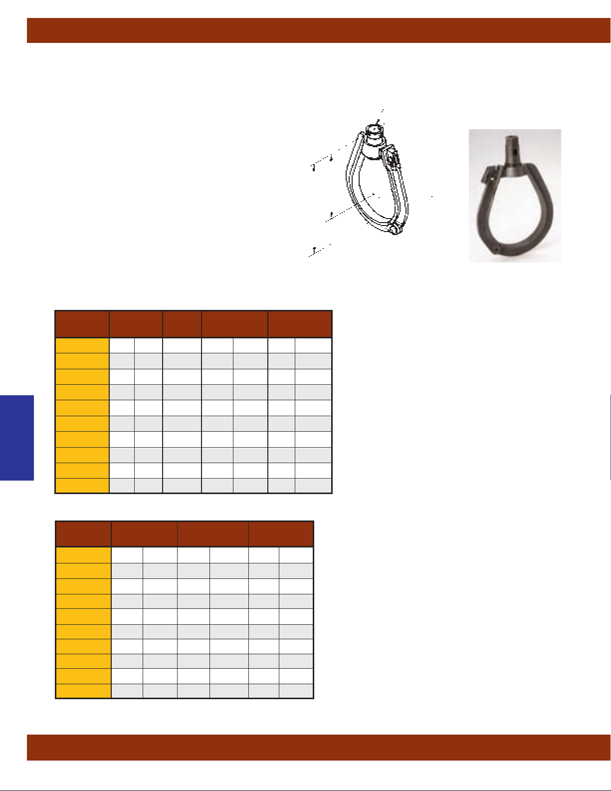
Pipe Hangers
Fig. B3171 - Adjustable Swivel Ring
Size Range:3/4” (20mm) to 6”
(150mm)
pipe
Material: Malleable Iron
Function: Designed to support pipe. Hanger may be
installed prior to hoisting pipe in place.
Approvals: Conforms to Federal Specification WW-H-171E
A-A-1192A, Type 6 and Manufacturers Standardization
&
Society ANSI/MSS SP-69 & SP-58, Type 6.
Standard Finish: Plain or Electro-Galvanized
Order By: Figure number and finish.
Note:
3
Hanger sizes
/4" (20) thru 2" (50) swivel nut is flared as
shown in drawing.
1
Hanger sizes 2
/2" (65) thru 6" (150) swivel nut has wire
retaining ring.
Pipe Size Rod Size B C
Part No.
B3171-3/4
in. (mm)
3
/4" (20)3/8"-16 21/8" (54.0) 25/8" (66.7)
A
in. (mm) in. (mm)
B3171-1 1" (25)3/8"-16 25/16" (58.7) 3" (76.2)
B3171-11/4 11/4" (32)3/8"-16 29/16" (65.1) 33/8" (85.7)
B3171-11/2 11/2" (40)3/8"-16 23/4" (69.8) 33/4" (95.2)
Pipe Hangers
B3171-2 2" (50)3/8"-16 31/16" (77.8) 41/4" (107.9)
B3171-21/2 21/2" (65)1/2"-13 45/16" (109.5) 53/4" (146.0)
B3171-3 3" (80)1/2"-13 45/8" (117.5) 63/8" (161.9)
B3171-4 4" (100)5/8"-11 6" (152.4) 81/4" (209.5)
B3171-5 5" (125)5/8"-11 63/4" (171.4) 91/2" (241.3)
B3171-6 6" (150)3/4"-10 711/16" (195.3) 11" (279.4)
A
(Rod Size)
B
C
Pipe Size Design Load Approx. Wt./100
Part No.
B3171-3/4
in. (mm)
3
/4" (20) 300 (1.33) 23 (10.4)
lbs. (kN) lbs. (kg)
B3171-1 1" (25) 300 (1.33) 25 (11.3)
B3171-11/4 11/4" (32) 300 (1.33) 30 (13.6)
B3171-11/2 11/2" (40) 300 (1.33) 32 (14.5)
B3171-2 2" (50) 300 (1.33) 34 (15.4)
B3171-21/2 21/2" (65) 500 (2.22) 65 (29.5)
B3171-3 3" (80) 500 (2.22) 78 (35.4)
B3171-4 4" (100) 900 (4.00) 154 (69.8)
B3171-5 5" (125) 900 (4.00) 200 (90.7)
B3171-6 6" (150) 1300 (5.78) 320 (145.1)
All dimensions in charts and on drawings are in inches. Dimensions shown in parentheses are in millimeters unless otherwise specified.
66
Page 69
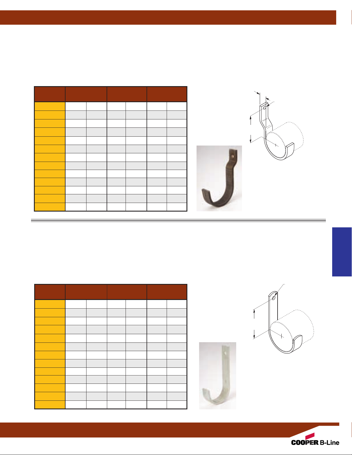
Fig. B3190 Return Line Offset J-Hook (TOLCO Fig. 40)
Pipe Hangers
Size Range:1/2” (15mm) to 8”
(200mm)
pipe
Material: Steel (Stainless steel available)
Function: Recommended for supporting light pipe runs with a 1"
(25.4) offset from mounting surfaces.
Standard Finish: Plain or Electro-Galvanized. Contact Cooper B-Line for alternative finishes and materials.
Order By: Figure number and finish.
Pipe Size Design Load Approx. Wt./100
1"
(25.4)
Part No. in. (mm) Lbs. (kN) Lbs. (kg)
B3190-1/2
B3190-3/4
B3190-1 1" (25) 200 (.89) 78 (35.4)
B3190-11/4 11/4" (32) 200 (.89) 85 (38.5)
1
/2" (15) 200 (.89) 54 (24.5)
3
/4" (20) 200 (.89) 55 (24.9)
5"
(127.0)
B3190-11/2 11/2" (40) 200 (.89) 90 (40.8)
B3190-2 2" (50) 200 (.89) 98 (44.4)
B3190-21/2 21/2" (65) 350 (1.55) 126 (57.1)
B3190-3 3" (80) 350 (1.55) 136 (61.7)
B3190-31/2 31/2" (90) 350 (1.55) 147 (66.8)
B3190-4 4" (100) 450 (2.00) 235 (106.6)
B3190-5 5" (125) 450 (2.00) 350 (158.7)
B3190-6 6" (150) 450 (2.00) 383 (173.7)
B3190-8 8" (200) 450 (2.00) 605 (274.4)
9
/16" Dia.
(14.3)
Fig. B3191 Return Line Straight J-Hook (TOLCO Fig. 41)
Size Range:1/2” (15mm) to 8”
Material: Steel (Stainless steel available)
Function: Recommended for supporting light pipe runs with a 1"
Standard Finish: Plain or Electro-Galvanized. Contact Cooper B-Line for alternative finishes and materials.
Order By: Figure number and finish.
Pipe Size Design Load Approx. Wt./100
Part No. in. (mm) Lbs. (kN) Lbs. (kg)
B3191-1/2
B3191-3/4
1
/2" (15) 200 (.89) 54 (24.5)
3
/4" (20) 200 (.89) 55 (24.9)
B3191-1 1" (25) 200 (.89) 76 (34.5)
B3191-11/4 11/4" (32) 200 (.89) 82 (37.2)
B3191-11/2 11/2" (40) 200 (.89) 87 (39.4)
B3191-2 2" (50) 200 (.89) 96 (43.5)
B3191-21/2 21/2" (65) 350 (1.55) 124 (56.2)
B3191-3 3" (80) 350 (1.55) 134 (60.8)
B3191-31/2 31/2" (90) 350 (1.55) 145 (65.8)
B3191-4 4" (100) 450 (2.00) 153 (69.4)
B3191-5 5" (125) 450 (2.00) 348 (157.8)
B3191-6 6" (150) 450 (2.00) 381 (172.8)
B3191-8 8" (200) 450 (2.00) 600 (272.1)
(200mm)
pipe
(25.4) offset from mounting surfaces.
5"
(127.0)
9
/16" Dia.
(14.3)
Pipe Hangers
All dimensions in charts and on drawings are in inches. Dimensions shown in parentheses are in millimeters unless otherwise specified.
67
Page 70

Pipe Hangers
Fig. 120 - “U” Hanger
Size Range: Size 3/4" (20mm) thru 8" (200mm) pipe
Material: Steel
Function: Used to support piping from wood beams where
no contraction is expected. Used extensively in automatic
fire sprinkler systems.
Approvals: Meets or exceeds the requirements of National
Fire Protection Association (NFPA), Pamphlet 13. Included
in our Seismic Restraints Catalog approved by the State of
California Office of Statewide Health Planning and
Development (OSHPD). For additional load, spacing and
placement information relating to OSHPD projects, please
refer to the Cooper B-Line Seismic Restraint Systems
Guidelines.
Maximum Temperature: 750°F
(399°C)
Finish: Plain. Contact Cooper B-Line for alternative
finishes and materials.
Order By: Figure number, pipe size, length and finish
™
A
Length
(Specify)
Pipe Hangers
Pipe Size A Fastener Size Max. Rec. Load***
Part No.
120-3/4
in. (mm) in. (mm) lbs. (kN)
3
/4" (20)
120-1 1" (25)
120-11/4 11/4" (32)
120-11/2 11/2" (40)
120-2 2" (50)
120-21/2 21/2" (65)
120-3 3" (80)
120-31/2 31/2" (90)
120-4 4" (100)
120-5 5" (125)
120-6 6" (150)
120-8 8" (200)
5
/16" (7.9) 16 x 2* 250 (1.11)
5
/16" (7.9) 16 x 2* 250 (1.11)
5
/16" (7.9) 16 x 2* 250 (1.11)
5
/16" (7.9) 16 x 2* 250 (1.11)
5
/16" (7.9) 16 x 2* 250 (1.11)
3
/8" (9.5)
3
/8" (9.5)
3
/8" (9.5)
3
/8" (9.5)
1
/2" (12.7)
1
/2" (12.7)
1
/2" (12.7)
3
/8 x 21/2** 320 (1.42)
3
/8 x 21/2** 320 (1.42)
3
/8 x 21/2** 560 (2.49)
1
/2 x 3** 560 (2.49)
1
/2 x 3** 560 (2.49)
1
/2 x 3** 760 (3.38)
5
/8 x 3** -- (--)
* Drive Screw
** Lag Bolt
*** With minimum safety factor of 5
Fastener schedule per NFPA
All dimensions in charts and on drawings are in inches. Dimensions shown in parentheses are in millimeters unless otherwise specified.
68
Page 71

Fig. 120MJ - Mutt & Jeff “U” Hanger
Pipe Hangers
Size Range: Size 3/4" (20mm) thru 8" (200mm) pipe
Material: Steel
Function: Used to support piping from wood beams where no
contraction is expected. Used extensively in automatic fire
sprinkler systems. Fig. 120MJ is used when the wood beam is
on a diagonal.
Finish: Plain. Contact Cooper B-Line for alternative finishes
and materials.
Order By: Figure number, side length and finish
Pipe Size A Fastener Size Max. Rec. Load***
Part No.
120MJ-3/43/4" (20)
120MJ-1 1" (25)
120MJ-11/4 11/4" (32)
120MJ-11/2 11/2" (40)
120MJ-2 2" (50)
120MJ-21/2 21/2" (65)
120MJ-3 3" (80)
120MJ-31/2 31/2" (90)
120MJ-4 4" (100)3/8" (9.5)
120MJ-5 5" (125)1/2" (12.7)
120MJ-6 6" (150)1/2" (12.7)
120MJ-8 8" (200)1/2" (12.7)
in. (mm) in. (mm) lbs. (kN)
5
/16" (7.9) 16 x 2* 250 (1.11)
5
/16" (7.9) 16 x 2* 250 (1.11)
5
/16" (7.9) 16 x 2* 250 (1.11)
5
/16" (7.9) 16 x 2* 250 (1.11)
5
/16" (7.9) 16 x 2* 250 (1.11)
3
/8" (9.5)3/8 x 21/2** 320 (1.42)
3
/8" (9.5)3/8 x 21/2** 320 (1.42)
3
/8" (9.5)3/8 x 21/2** 560 (2.49)
1
/2 x 3** 560 (2.49)
1
/2 x 3** 560 (2.49)
1
/2 x 3** 760 (3.38)
5
/8 x 3** -- (--)
™
A
Length
(Specify)
* Drive Screw
** Lag Bolt
*** With minimum safety factor of 5
Fastener schedule per NFPA
Fig. 120W - Wrap Around “U” Hanger
Size Range: Size 3/4" (20mm) thru 2" (50mm) pipe
Material: Steel
Function: Required for automatic fire protection agencies to
be used on the end of branch lines to prevent pipe from
whipping vertical and striking ceiling or beam.
Finish: Plain. Contact Cooper B-Line for alternative finishes
and materials.
Order By: Figure number, side length and finish
Pipe Size A Fastener Size Max. Rec. Load***
Part No.
120W-3/4
120W-1 1" (25)
120W-11/4 11/4" (32)
120W-11/2 11/2" (40)
120W-2 2" (50)
in. (mm) in. (mm) lbs. (kN)
3
/4" (20)
All dimensions in charts and on drawings are in inches. Dimensions shown in parentheses are in millimeters unless otherwise specified.
5
/16" (7.9) 16 x 2* 250 (1.11)
5
/16" (7.9) 16 x 2* 250 (1.11)
5
/16" (7.9) 16 x 2* 250 (1.11)
5
/16" (7.9) 16 x 2* 250 (1.11)
5
/16" (7.9) 16 x 2* 250 (1.11)
™
Length
(Specify)
* Drive Screw
*** With minimum safety factor of 5
Fastener schedule per NFPA
Pipe Hangers
A
69
Page 72
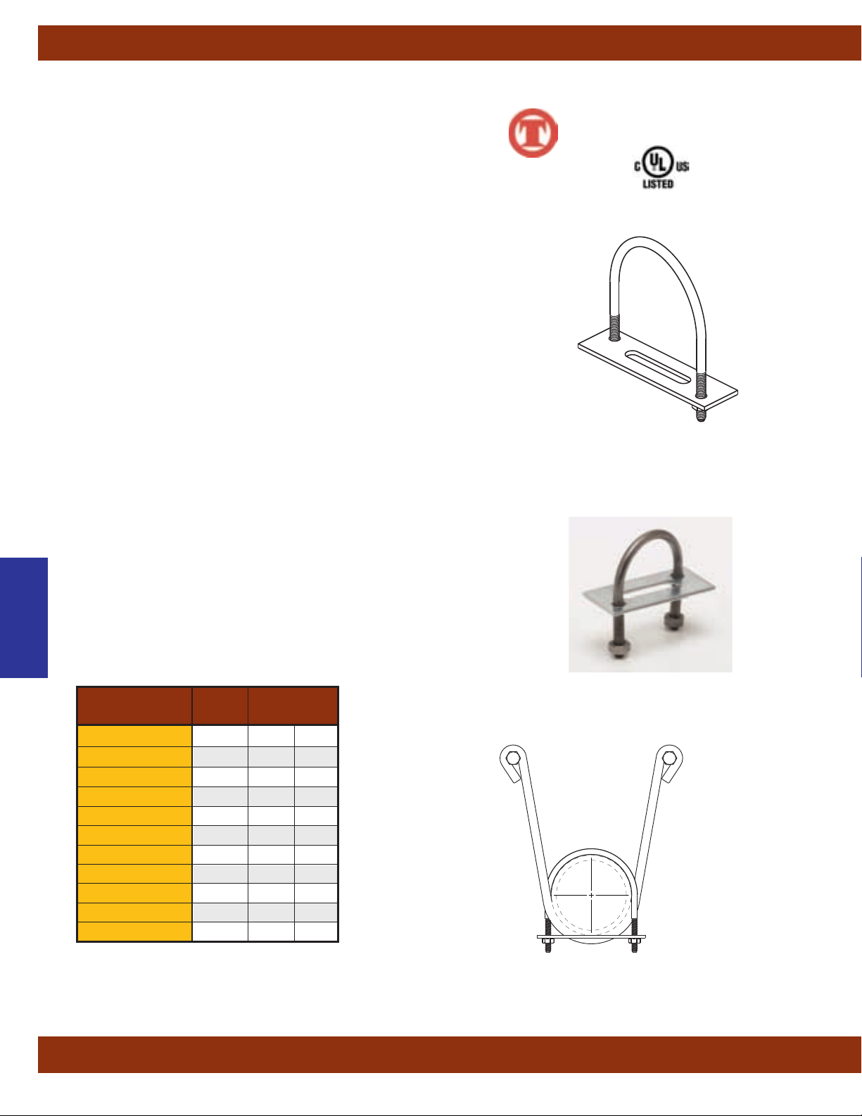
Pipe Hangers
Fig. 120RWA - (Model B) Retrofit Wrap Around “U” Hanger Clamp
Size Range: 1" (25mm) thru 8" (200mm) pipe
Material: Steel
Function: Designed to restrain movement of the pipe within standard
U-hangers as required by NFP
Fig. 120RWA is a labor efficient alternative to the standard Cooper B-Line
Fig. 120W wrap around U-hanger.
Features Installs easily by tightening two hex nuts. Features a unique
bracing slot that locks onto a standard U-hanger to become a solid unit that
will stabilize the pipe during seismic activity or sprinkler head activation.
Designed to be used in retrofit or new construction applications. Will clamp
to existing U-Hangers without restriction to leg angle.
Approvals: Underwriters Laboratories listed in the USA (UL) and Canada
(cUL) as a restrainer. Included in our Seismic Restraints Catalog approved
by the State of California Of
Development (OSHPD). For additional load, spacing and placement
information relating to OSHPD projects, please refer to the Cooper B-Line
Seismic Restraint Systems Guidelines. NFP
Finish: Plain and Galvanized. Contact Cooper B-Line for alternative finishes
and materials.
Order By: Figure number, type numbers and pipe size
Ordering Note: Order by the following type and pipe size:
Type 1 — (1"
Type 2 — (1
Type 3 — (2
(25mm) and 1
1
/2" (40mm) and 2" (50mm) pipe size)
1
/2" (65mm) and 3" (80mm) pipe size)
Type 4 — (4" (100mm) pipe size)
Type 6 — (5" (125mm) and 6" (150mm) pipe size)
Type 8 — (8" (200mm) pipe size)
Important Note: The bracing slot feature is sized to fit the U-Hanger rod
Pipe Hangers
schedule as required by NFP
5
/16" (7.9mm) rod for up to 2" (50mm) pipe
3
/8" (9.5mm) rod for 21/2" (65mm) - 6" (160mm) pipe
1
/2" (12.7mm) rod for 8" (200mm) pipe
For other rod size requirements consult factory.
A 13. Where retrofit capability is crucial, the
fice of Statewide Health Planning and
A 13 (2010) 9.3.6.3.
1
/4" (32mm) pipe size)
A 13 as follows:
Component of State of
California OSHPD Approved
Seismic Restraints System
™
Type Pipe Size
Part No.
in. (mm)
120RWA-TYPE1-1 11"(20)
120RWA-TYPE1-11/4 11
1
/4" (25)
120RWA-TYPE2-11/2 2 11/2" (40)
120RWA-TYPE2-2 22"(50)
120RWA-TYPE3-21/2 32
1
/2" (65)
120RWA-TYPE3-3 3 3" (80)
120RWA-TYPE4-31/2 4 31/2" (90)
120RWA-TYPE4-4 44"(100)
120RWA-TYPE6-5 65"(125)
120RWA-TYPE6-6 6 6" (150)
120RWA-TYPE8-8 88"(200)
All dimensions in charts and on drawings are in inches. Dimensions shown in parentheses are in millimeters unless otherwise specified.
70
Page 73

Pipe Hangers
Fig. B3262 Light Duty Spring Hanger
Rod Size Range:3/8”-16 to 3/4”-10
Material: Steel
Service: Designed for use with a light piping system where
vertical movement does not exceed 1
Approvals: Conforms to Federal Specification WW-H-171E
A-A-1192A, Type 29 and Manufacturers Standardization
&
Society ANSI/MSS SP-69 & SP-58, Type 48.
Order By: Figure number.
Rod Size Spring B C D
Part No. A Color
B3262-3/8
B3262-1/2
B3262-5/8
B3262-3/4
3
/8"-16 Brown 2" (50.8) 23/4" (69.8) 41/2" (114.3)
1
/2"-13 Black 2" (50.8) 23/4" (69.8) 41/2" (114.3)
5
/8"-11 Red 2" (50.8) 23/4" (69.8) 41/2" (114.3)
3
/4"-10 Orange 2" (50.8) 3" (76.2) 7" (177.8)
1
/4" (31.7).
In (mm) In (mm) In (mm)
A
(Rod Size)
C
D
B
A
(Rod Size)
Spring Deflection Rated Load Approx. Wt./100
Part No.
In (mm) Lbs. (kN) Lbs. (kg)
B3262-3/8 1.20 (30.1) 100-150 (.44 - .67) 390 (176.2)
B3262-1/2 1.10 (27.7) 150-250 (.67 - 1.11) 410 (186.0)
B3262-5/8 1.00 (25.4) 350-450 (1.56 - 2.00) 470 (213.2)
B3262-3/4 1.20 (30.1) 600-750 (2.67 - 3.34) 1240 (562.6)
Pipe Hangers
All dimensions in charts and on drawings are in inches. Dimensions shown in parentheses are in millimeters unless otherwise specified.
71
Page 74

Pipe Hangers
Fig. BH-2-4, BH-5-8, BH-9-12 - Parallel Strap Hangers
Fig. BH-2-4-R, BH-5-8-R, BH-9-12-R - Right Angle Strap Hangers
Material: Steel
Function: The Parallel Strap Hanger series is
designed for suspending up to 1"
straps parallel to beams.
The Right Angle Strap Hanger series is designed
for suspending up to 1"
(50.8) wide straps at right
angle to the beam.
Note: Install clip to beam with hammer.
Standard Finish: Zinc Phosphate
Order By: Figure number and finish.
Part No. Flange Thickness Maximum Load BH-2-12 BH-2-12R
Parallel Right Angle
BH-2-4 BH-2-4-R
BH-5-8 BH-5-8-R
BH-9-12 BH-9-12-R
Design Load is a static straight down load.
(50.8) wide
Parallel
Strap
In. (mm) Lbs. (kN) Lbs. (kg) Lbs. (kg)
1
/8" to 1/4" (3.2 to 6.3) 200 (.89) 4.5 (2.0) 6.0 (2.7)
5
/16" to 1/2" (7.9 to 12.7) 200 (.89) 5.0 (2.3) 6.5 (2.9)
9
/16" to 3/4" (14.3 to 19.0) 200 (.89) 5.5 (2.5) 7.0 (3.2)
Right Angle
Strap
Approx. Wt./100
Fig. BL1400 - Hanger
Size Range:1/2” (15mm) to 4”
Pipe Hangers
Material: Steel
Function: Designed to support or suspend light
duty stationary pipe runs.
Standard Finish: Electro-Galvanized
Order By: Figure number.
Part No.
BL1400
BL1410
In. (mm) In. (mm) In. (mm) In. (mm) In. (mm)
1
3
BL1420 1" (25) 11/4" (31.7)
BL1430 11/4" (32) 113/32" (35.7)
BL1440 11/2" 40) 55/8" (41.3)
BL1450 2" (50) 17/8" (47.6)
BL1460 21/2" (65) 21/16" (52.4)
BL1470 3" (80) 21/2" (63.5)
BL1480 31/2" (90) 23/4" (69.8)
BL1490 4" (100) 31/2" (88.9)
Designed for positioning only, no load rating.
All dimensions in charts and on drawings are in inches. Dimensions shown in parentheses are in millimeters unless otherwise specified.
(100mm)
Pipe Size A B T W Approx. Wt./100
/2" (15)
/4" (20)
pipe
29
/32" (23.0)
31
/32" (24.6)
W
T
9
/32" (7.1) 16 Ga. (1.5)
9
/32" (7.1) 16 Ga. (1.5)
9
/32" (7.1) 16 Ga. (1.5)
9
/32" (7.1) 18 Ga. (1.5)
11
/32" (8.7) 16 Ga. (1.5) 1" (25.4) 17 (7.7)
11
/32" (8.7) 16 Ga. (1.5) 11/4" (31.7) 25 (11.3)
11
/32" (8.7) 16 Ga. (1.5) 11/4" (31.7) 26 (11.8)
11
/32" (8.7) 16 Ga. (1.5) 11/4" (31.7) 33 (14.9)
11
/32" (8.7) 16 Ga. (1.5) 11/4" (31.7) 36 (16.3)
11
/32" (8.7) 16 Ga. (1.5) 11/4" (31.7) 40 (18.1)
3
/4" (19.0) 6 (2.7)
3
/4" (19.0) 7 (3.2)
3
/4" (19.0) 8 (3.6)
7
/8" (22.2) 10 (4.5)
Pipe Size
A
Hole Size B
Lbs. (kg)
72
Page 75

Pipe Hangers
All dimensions in charts and on drawings are in inches. Dimensions shown in parentheses are in millimeters unless otherwise specified.
73
Pipe Hangers
Page 76

Pipe Clamps
Pipe clamps offered in this section are designed for support and attachment of pipe to structural members. A wide
range of pipe clamps are available for various applications.
Materials
Pipe Clamps
Carbon Steel is used in the manufacturing of riser and pipe clamps. Stainless Steel and other materials are available.
Finishes
The standard finishes for mechanical supports are plain steel (oil coated) sometimes referred to as black and ElectroGalvanized Zinc (ASTM B 633 SC3). Hot-Dip Galvanized After Fabrication (ASTM A 123), Red Primer, Plastic Coating,
DURA-GREEN
™, DURA-COPPER™ and other special coatings are available upon request.
Note: Due to the design of some products, (threads, connecting hardware, swivels, etc.) items may or may not be
uniformly coated with special finishes. In some cases, the hanger itself may be coated, however, the hardware may
be supplied Electro-Plated, Copper Plated, or in Stainless Steel.
Recommended Torque (Pipe Clamp Hardware)
1
/4”-20
6 ft/lbs
(8 Nm)
5
/16”-18
11 ft/lbs
(19 Nm)
3
/8”-16
19 ft/lbs
(26 Nm)
1
/2”-13
50 ft/lbs
(68 Nm)
5
/8”-11
65 ft/lbs
(88 Nm)
3
/4”-10 & larger
75 ft/lbs
(101 Nm)
Approvals (as noted)
Items in this section are Underwriters Laboratories Listed, Factory Mutual Approved, and comply with Federal
Specification WW-H-171E & A-A-1192A or Manufacturers Standardization Society ANSI/MSS SP-69 & SP-58.
All pipe hangers and supports in this section are sized to fit schedule 40/80 pipe unless otherwise noted. Some steel
items may be specially fabricated to fit other pipe diameters i.e. ductile iron, cast iron, etc. Select pipe O.D. from
charts on pages 294 thru 300.
All dimensions in charts and on drawings are in inches. Dimensions shown in parentheses are in millimeters unless otherwise specified.
74
Page 77
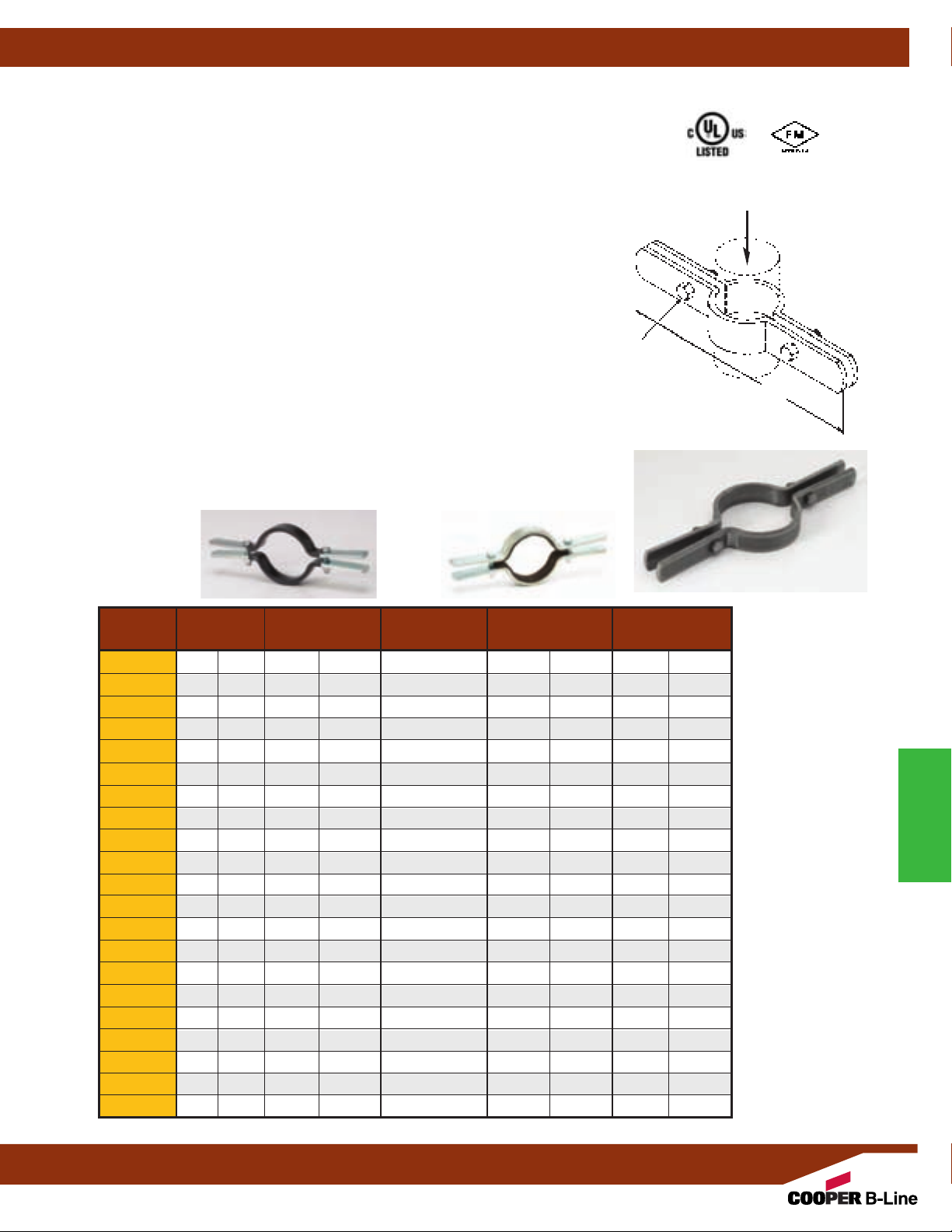
Fig. B3373 - Standard Riser Clamp (TOLCO Fig. 6)
Fig. B3373F - Felt Lined Standard Riser Clamp (TOLCO Fig. 6F)
Fig. B3373C - PVC Coated Standard Riser Clamp (TOLCO Fig. 6PVC)
Size Range: (B3373) 1/2"
(B3373F)
(B3373C)
1
1
/2"
/2"
(15mm)
(15mm)
Material: Steel
Insulation Material: (Fig. 6F)
Function: Used for supporting vertical piping.
Approvals: Underwriters Laboratories Listed in the USA (UL), Canada (cUL)
3
/4"
(20mm)
- 8"
(200mm)
(200mm)
. Conforms to Federal Specification WW-H-171E & A-A-1192A, Type 8,
and Manufacturers Standardization Society ANSI/MSS SP-69 & SP-58, Type 8.
Maximum Temperature: 650°F
Finish: Plain. Contact Cooper B-Line for alternative finishes and materials.
Order By:
(B3373 and B3373C) pipe size and finish.
(B3373F) copper tube size and finish.
B3373F is available for Iron Pipe Size, consult factory
(15mm)
thru 21/2"
thru 6"
thru 30"
(65mm)
(150mm)
3
/16"
(760mm)
copper tubing
pipe
(4.8mm)
felt.
pipe
. Factory Mutual Engineering Approved, 3/4"
(343°C)
.
(20mm)
thru 8"
Pipe Clamps
Design Load
Bolt Size
L
Bolts and Nuts Included
B3373C
B3373F
Pipe Size L Design Load Approx. Wt./100
Part No. in. (mm) in. (mm) Bolt Size Lbs. (kN) Lbs. (kg)
B3373-1/21/2" (15) 9" (228.6)
B3373-3/43/4" (20) 91/4" (234.9)
B3373-1 1" (25) 99/16" (242.9)
B3373-11/4 11/4" (32) 10" (254.0)
B3373-11/2 11/2" (40) 101/4" (260.3)
B3373-2 2" (50) 103/4" (273.0)
B3373-21/2 21/2" (65) 111/4" (285.7)
B3373-3 3" (80) 1115/16" (303.2)
B3373-31/2 31/2" (90) 123/8" (314.3)
B3373-4 4" (100) 127/8" (327.0)
B3373-5 5" (125) 14" (355.6)
B3373-6 6" (150) 153/16" (385.8)
B3373-8 8" (200) 173/4" (450.8)
B3373-10 10" (250) 197/16" (493.7)
B3373-12 12" (300) 2111/16" (550.9)
B3373-14 14" (350) 239/16" (598.5)
B3373-16 16" (400) 263/8" (669.9)
B3373-18 18" (450) 287/8" (733.4)
B3373-20 20" (500) 307/8" (784.2)
B3373-24 24" (600) 347/8" (885.8)
B3373-30 30" (750) 403/4" (1035.0)
All dimensions in charts and on drawings are in inches. Dimensions shown in parentheses are in millimeters unless otherwise specified.
3
/8"-16 x 11/4" 255 (1.13) 101 (45.9)
3
/8"-16 x11/4" 255 (1.13) 105 (47.7)
3
/8"-16 x 11/4" 255 (1.13) 109 (49.4)
3
/8"-16 x 11/4" 255 (1.13) 112 (50.9)
3
/8"-16 x 11/2" 255 (1.13) 113 (51.1)
3
/8"-16 x 11/2" 255 (1.13) 165 (75.0)
3
/8"-16 x 11/2" 390 (1.73) 180 (81.6)
3
/8"-16 x 11/2" 530 (2.35) 195 (88.4)
1
/2"-13 x 13/4" 670 (2.98) 217 (98.5)
1
/2"-13 x 13/4" 810 (3.60) 228
1
/2"-13 x 13/4" 1160 (5.16) 480
1
/2"-13 x2" 1570 (6.98) 526
5
/8"-11 x 21/2" 2500 (11.12) 957
5
/8"-11 x21/2" 2500 (11.12) 1101
5
/8"-11 x 3" 2700 (12.01) 1622
5
/8"-11 x 3" 2700 (12.01) 1732
3
/4"-10 x 31/4" 2900 (12.90) 2959
3
/4"-10 x 31/4" 2900 (12.90) 3235
3
/4"-10 x 31/2" 2900 (12.90) 3568
3
/4"-10 x 31/2" 2900 (12.90) 4064
7
/8"-9 x 31/2" 2900 (12.90) 6016
(103.5)
(217.7)
(238.6)
(434.1)
(499.4)
(735.7)
(785.6)
(1342.2)
(1467.4)
(1618.4)
(1843.3)
(2728.8)
Notes: For ductile iron
(D.I.) pipe use part
number B3373CI-pipe
size. Contact B-Line
Engineering for more
information.
Pipe Clamps
75
Page 78
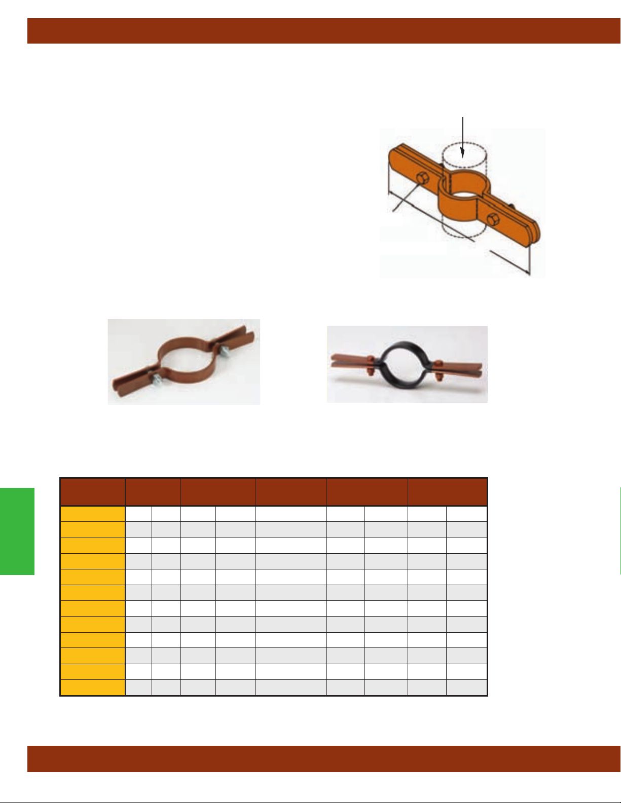
Pipe Clamps
Fig. B3373CT - Cooper Tubing Riser Clamp (TOLCO Fig. 82)
Fig. B3373CTC - PVC Coated Cooper Tubing Riser Clamp (TOLCO Fig. 82PVC)
Size Range: — Size 1/2"
(15mm)
thru 6"
(150mm)
copper tubing
Material: — Steel
Function: — Used for supporting vertical copper tubing.
Approvals: — Conforms to Federal Specification WW-H-171E &
A-A-1
192A Type 8 and Manufacturers Standardization Society
ANSI/MSS SP-69 & SP-58 Type 8.
Finish: — DURA-COPPER™
Note: — Available with plastic coating, specify by ordering B3373CTC
Order By: — Figure number and nominal tubing size
Bolt Size
Bolts and Nuts Included
Design Load
L
Pipe Clamps
B3373CT-11/4 11/4" (32) 95/8" (244.5)
B3373CT-11/2 11/2" (40) 93/4" (247.6)
B3373CT-21/2 21/2" (65) 1015/16" (277.8)
B3373CT-31/2 31/2" (90) 1115/16" (303.2)
B3373CT
Tubing Size L Design Load Approx. Wt./100
Part No.
B3373CT-1/2
B3373CT-3/4
in. (mm) in. (mm) Bolt Size Lbs. (kN) Lbs. (kg)
1
/2" (15) 83/4" (222.2)
3
/4" (20) 91/16" (234.9)
B3373CT-1 1" (25) 95/16" (236.5)
B3373CT-2 2" (50) 107/16" (265.1)
B3373CT-3 3" (80) 117/16" (290.5)
B3373CT-4 4" (100) 121/2" (317.5)
B3373CT-5 5" (125) 135/8" (346.1)
B3373CT-6 6" (150) 145/8" (371.5)
B3373CTC
5
/16"-18 x 1" 75 (.33) 72 (32.6)
5
/16"-18 x 1" 75 (.33) 73 (33.2)
3
/8"-16 x 1" 120 (.53) 74 (33.6)
3
/8"-16 x 1" 150 (.67) 77 (34.8)
3
/8"-16 x11/4" 150 (.67) 111 (50.3)
3
/8"-16 x11/4" 150 (.67) 120 (54.5)
3
/8"-16 x 11/4" 300 (1.33) 128 (58.1)
3
/8"-16 x 11/4" 300 (1.33) 136 (61.5)
3
/8"-16 x 11/4" 300 (1.33) 145 (65.7)
1
/2"-13 x 13/4" 300 (1.33) 170
1
/2"-13 x 2" 500 (2.22) 355
1
/2"-13 x 2" 500 (2.22) 386
(77.3)
(161.0)
(175.1)
All dimensions in charts and on drawings are in inches. Dimensions shown in parentheses are in millimeters unless otherwise specified.
76
Page 79

Pipe Clamps
Fig. B3132 - Two-Bolt Underground Clamp (TOLCO Fig. 9)
Size Range: 4" (100mm) thru 24" (600mm) pipe
Material: Steel
Function: Clamp is used for underground A.W.W.A. cast iron and
ductile iron water pipe to prevent joints from separating.
the A.W.W.A. pipe is shown in the data table.
Finish: Plain. Contact Cooper B-Line for alternative finishes and
materials.
Order By: Figure number, pipe size and outside diameter of pipe.
Order B3132W lugs, tie rods and hex nuts separately
Pipe Size A B Clamp ‘I.D.’ Steel Size Approx. Wt./100
Part No. in. (mm) in. (mm) in. (mm) in. (mm) in. (mm) Bolt Size Lbs. (kg)
B3132-4 4" (100) 127/8" (327.0) 93/4" (247.6) 5" (127.0)1/2"x 2" (12.7 x 50.8)5/8"-11x 3" 864 (391.9)
B3132-6 6" (150) 143/4" (374.6) 12" (304.8) 71/16" (179.4)1/2"x2" (12.7x 50.8)5/8"-11 x 3" 1020 (462.6)
B3132-8 8" (200) 171/4" (438.1) 141/4" (361.9) 93/16" (233.4)1/2"x2" (12.7 x 5 0.8)
B3132-10 10" (250) 193/8" (492.1) 161/2" (419.1) 113/8" (288.9)1/2"x2" (12.7x 50.8)5/8"-11 x 3" 1409 (639.1)
B3132-12 12" (300) 217/8" (555.6) 187/8" (479.4) 131/2" (342.9)1/2"x2" (12.7x 50.8)5/8"-11 x 3" 1608 (729.4)
B3132-14 14" (350) 26" (660.4) 221/4" (565.1) 153/4" (400.0)3/4"x3" (19.0x 76.2)7/8"-9 x 41/2" 4359 (1977.2)
B3132-16 16" (400) 283/8" (720.7) 245/8" (625.5) 177/8" (454.0)3/4"x4" (19.0x 101.6) 1"-8 x 41/2" 6403 (2904.4)
B3132-18 18" (450) 313/8" (796.9) 275/8" (701.7) 20" (508.0)3/4"x 4" (19.0 x 101.6) 11/4"-7 x 5" 7293 (3308.1)
B3132-20 20" (500) 331/2"(850.9) 293/4" (755.6) 221/8" (562.0)3/4"x41/2" (19.0 x 114.3) 11/4"-7 x 5" 8778 (3981.7)
B3132-24 24" (600) 39" (990.6) 351/4" (895.3) 263/8" (669.9)3/4"x 5" (19.0 x 127.0) 11/4"-6 x 51/2" 11659
The O.D. of
.
A
Bolts and Nuts Included
B
5
/8"-11 x 3" 1222 (554.3)
Steel Size
Bolt Size
(5288.5)
Fig. B3132W - Lug Washer (TOLCO Fig. 9X)
Size Range:3/4" (20mm) thru 11/2" (40mm) rod
E
D Dia.
E
Material: Cast Iron
Function: Used with B3132 to secure tie rods. The projecting
lug bears against the clamp bolt to prevent washer and tie rod
from slipping of
f clamp.
Finish: Plain. Contact Cooper B-Line for alternative finishes
and materials.
B3132W-
H
G
3
/4
F
B3132W-1
1
thru 1
G
/2
Order By: Figure number, rod size and finish
Tie Rod
Use With Pipe Size Dia. E F G H Approx. Wt./100
Part No. Size in. (mm) in. (mm) in. (mm) in. (mm) in. (mm) in. (mm) Lbs. (kg)
B3132W-3/4
3
/4"-10 4"-12"
B3132W-1 1"-8 14"-16"
(100-300)
(350-400)
7
/8" (22.2) 23/8" (60.3) -- --
5
/8" (15.9) 15/8" (41.3) 74 (33.7)
11/8" (28.6) 31/2" (88.9) 31/2" (88.9)5/8" (15.9) 21/2" (63.5) 207 (93.9)
B3132W-11/4 11/4"-7 18" (450) 13/8" (34.9) 31/2" (88.9) 4" (101.6)5/8" (15.9) 31/2" (63.5) 236 (107.0)
B3132W-13/8 13/8"-6 20" (500) 11/2" (38.1) 4" (101.6) 41/4" (107.9)5/8" (15.9) 4" (101.6) 231 (104.8)
B3132W-11/2 11/2"-6 24" (600) 15/8" (41.3) 4" (101.6) 43/4" (120.6)5/8" (15.9) 4" (101.6) 259 (117.5)
All dimensions in charts and on drawings are in inches. Dimensions shown in parentheses are in millimeters unless otherwise specified.
77
D Dia.
H
Pipe Clamps
Page 80

Pipe Clamps
B3134 - Double Bolt Underground Socket Clamp (TOLCO Fig. 14)
Size Range: 4" (100mm) thru 24" (600mm) pipe
Material: Steel
Function: Clamp is used for underground A.W.W.A. cast iron and
ductile iron water pipe to prevent joints from separating.
A.W.W.A. pipe is shown in the data table.
Approvals: Conforms to National Fire Protection Association (NFP
Pamphlet 24, 4"
(100mm) thru 12" (300mm) pipe sizes.
Finish: Plain. Contact Cooper B-Line for alternative finishes and
materials.
Order By: Figure number, pipe size and
outside diameter of pipe.
Order B3134W plate washers, tie rods
and hex nuts separately
.
Part Pipe Size A B Bolt B3134 Washer Size) Approx. Wt./100
No. in. (mm) in. (mm) in. (mm) Size lbs. (kg)
B3134-4 4.80" (121.9) 141/16" (357.2) 95/16" (236.5)5/8"-11 B3134W-3/4 1275 (578.3)
B3134-6 6.90" (175.3) 167/16" (417.5) 1111/16" (298.9)5/8"-11 B3134W-3/4 1455 (660.0)
B3134-8 9.05" (229.9) 195/8" (498.5) 147/8" (442.6)5/8"-11 B3134W-3/4 2350 (1065.9)
B3134-10 11.10" (281.9) 2113/16" (554.0) 171/16" (433.4)3/4"-10 B3134W-3/4 2925 (1326.8)
B3134-12 13.20" (335.3) 241/2" (622.3) 191/4" (488.9)
B3134-14 15.30" (388.6) 2615/16" (684.2) 2111/16" (550.9)
B3134-16 17.40" (441.9) 303/4" (781.0) 243/4" (628.6) 1"-8 B3134W-11/8 7645 (3467.8)
B3134-18 19.50" (495.3) 345/16" (871.5) 275/16" (693.7) 11/4"-7 B3134W-11/4 9425 (4275.2)
B3134-20 21.60" (548.6) 365/8" (930.3) 295/8" (752.5) 11/4"-7 B3134W-11/2 10975 (4978.2)
B3134-24 25.80" (655.3) 421/8" (1070.0) 343/8" (873.1) 11/2"-6 B3134W-11/2 14865 (6742.6)
The O.D. of the
A)
7
/8"-9 B3134W-1 4030 (1828.0)
7
/8"-9 B3134W-1 5385 (2442.6)
A
B
B3134W - Plate Washer (TOLCO Fig. 14X)
Pipe Clamps
Size Range:3/4"-10 thru 11/2"-6 rod
Material: Steel
Function: Used with B3134 to secure tie rods.
Finish: Plain. Contact Cooper B-Line for alternative finishes and materials.
Order By: Figure number, rod size and finish
Tie Rod Hole Size Approx.
Part Size A B C
No. in. (mm) in. (mm) in. (mm) lbs. (kg)
B3132W-3/43/4"-10 3" (76.2)1/2" (12.7)7/8" (22.2) 120 (54.4)
B3132W-1 1"-8 31/2" (88.9)1/2" (12.7) 11/8" (28.6) 157 (71.2)
B3132W-11/8 11/8"-7 31/2" (88.9)5/8" (15.9) 11/4" (31.7) 194 (88.0)
B3132W-11/4 11/4"-7 31/2" (88.9)3/4" (19.0) 13/8" (35.8) 230 (104.3)
B3132W-11/2 11/2"-6 31/2" (88.9)3/4" (19.0) 15/8" (41.2) 240 (108.8˛)
All dimensions in charts and on drawings are in inches. Dimensions shown in parentheses are in millimeters unless otherwise specified.
78
Wt./100
C
B
A
A
Page 81

Pipe Clamps
B3140 - Standard Pipe Clamp (TOLCO Fig. 4)
B3140F - Standard Pipe Clamp Felt Lined (TOLCO Fig. 4F)
B3140C - Standard Pipe Clamp PVC Coated (TOLCO Fig. 4PVC)
Size Range: B3140/B3140C Size 1/2"
B3140F Size
1
/2"
(15mm)
thru 21/2"
Material: Steel
Function: Recommended for the suspension of non-insulated pipe
or insulated pipe with B3151 shields. (Use B3200 weldless eye nut,
B3210 eye rod or B321
1 welded eye rod.) Also recommended for
attachment of sway bracing up to 3
sizes use Fig. 4A. B3140F and B3140C are designed to reduce noise
and vibration and/or prevent electrolysis.
Approvals: Underwriters Laboratories Listed in the USA (UL), Canada
3
(cUL)
/4"
(20mm)
- 12"
(300mm)
Engineering (FM),
3
/4"
(20mm)
, and approved by Factory Mutual
- 8"
WW-H-171E & A-A-1192A, Type 4, and Manufacturers Standardization
Society ANSI/MSS SP-69 & SP-58, Type 4. Included in our Seismic
Restraints Catalog approved by the State of California Office of
Statewide Health Planning and Development (OSHPD). For additional
load, spacing and placement information relating to OSHPD projects,
please refer to the Cooper B-Line/T
Guidelines.
Note: When the B3140 is used as a sway brace, to ensure
performance, the UL
Listing requires that it must be used with other
Cooper B-Line/TOLCO brace products.
Maximum Temperature: — 750°F
Finish: Plain. Contact Cooper B-Line for alternative finishes
and materials.
Order By: Figure number, pipe size and finish.
Order Note: When ordering B3140F allow for
each half of clamp.
(15mm)
(65mm)
1
/2"
(90mm)
(200mm)
thru 30"
copper tubing
pipe size, for larger pipe
. Federal Specification
(750mm)
pipe.
OLCO Seismic Restraint Systems
(399°C)
3
/16"
(4.8mm)
felt on
B3140
Component of State of
California OSHPD Approved
Seismic Restraints System
Bolt Size
B
C
B
C
A
B3140F
B3140C
Pipe Max. Design Load Approx.
Part Size A B C Bolt 650°F (343°C) 750°F (399°C) Wt./100
No. in. (mm) in. (mm) in. (mm) in. (mm) Size lbs. (kN) lbs. (kN) lbs. (kg)
B3140-1/21/2" (15)3/8" (9.5)31/32" (24.6) 117/32" (38.9)5/16"-18 500 (2.22) 390 (1.73) 30 (13.6)
B3140-3/43/4" (20)9/16" (14.3) 13/32" (27.8) 121/32" (42.0) 5/16"-18 500 (2.22) 390 (1.73) 31 (14.0)
B3140-1 1" (25)9/16" (14.3) 15/16" (33.3) 17/8" (47.6) 5/16"-18 500 (2.22) 390 (1.73) 33 (14.5)
B3140-11/4 11/4" (32)17/32" (13.5) 17/16" (36.5) 2" (50.8)5/16"-18 500 (2.22) 390 (1.73) 39 (17.7)
B3140-11/2 11/2" (40)19/32" (15.1) 121/32" (42.0) 27/32" (56.4)5/16"-18 800 (3.56) 620 (2.76) 41 (18.6)
B3140-2 2" (50)9/16" (14.3) 21/8" (54.0) 23/4" (69.8)1/2"-13 1040 (4.62) 810 (3.60) 118 (53.5)
B3140-21/2 21/2" (65)5/8" (15.9) 221/32" (67.5) 39/32" (83.3)1/2"-13 1040 (4.62) 810 (3.60) 130 (58.9)
B3140-3 3" (75)5/8" (15.9) 215/16" (74.6) 39/16" (90.5)1/2"-13 1040 (4.62) 810 (3.60) 150 (68.0)
B3140-31/2 31/2" (90)5/8" (15.9) 35/32" (80.1) 325/32" (96.0)1/2"-13 1040 (4.62) 810 (3.60) 158 (71.6)
B3140-4 4" (100)3/4" (19.0) 39/16" (90.5) 45/16" (109.5)5/8"-11 1040 (4.62) 810 (3.60) 239 (108.4)
B3140-5 5" (125)3/4" (19.0) 41/8" (104.8) 47/8" (123.8)5/8"-11 1040 (4.62) 810 (3.60) 272 (123.4)
B3140-6 6" (150)7/8" (22.2) 415/16" (125.4) 513/16" (147.6)3/4"-10 1615 (7.18) 1260 (5.60) 541 (245.4)
B3140-8 8" (200) 1" (25.4) 61/16" (154.0) 615/16" (176.2)3/4"-10 1615 (7.18) 1260 (5.60) 642 (291.2)
B3140-10 10" (250) 1" (25.4) 73/8" (187.3) 811/16" (220.7)
B3140-12 12" (300) 1" (25.4) 87/16" (214.3) 93/4" (247.6)
B3140-14 14" (350) 11/8" (28.6) 91/4" (234.9) 105/8" (269.9)
B3140-16 16" (400) 11/8" (28.6) 101/4" (260.3) 115/8" (295.3)
7
/8"-9 2490 (11.07) 1950 (8.67) 1366 (619.6)
7
/8"-9 2490 (11.07) 1950 (8.67) 1543 (699.9)
7
/8"-9 2490 (11.07) 1950 (8.67) 2077 (942.1)
7
/8"-9 2490 (11.07) 1950 (8.67) 2289 (1038.3)
B3140-18 18" (450) 11/4" (31.7) 117/8" (301.6) 131/4" (336.5) 1"-8 3060 (13.61) 2390 (10.63) 3206 (1454.2)
B3140-20 20" (500) 13/8" (34.9) 123/4" (323.8) 141/8" (358.8) 11/8"-7 3060 (13.61) 2390 (10.63) 3616 (1640.2)
B3140-24 24" (600) 15/8" (41.3) 151/4" (387.3) 167/8" (428.6) 11/4"-7 3060 (13.61) 2390 (10.63) 5161 (2341.0)
B3140-30 30" (750) 21/4" (57.1) 185/8" (473.1) 21" (533.4) 11/2"-6 3500 (15.57) 2740 (12.14) 10460 (4744.6)
All dimensions in charts and on drawings are in inches. Dimensions shown in parentheses are in millimeters unless otherwise specified.
Pipe Clamps
79
Page 82

Pipe Clamps
Fig. 4A - Pipe Clamp for Sway Bracing
Size Range: 4"
For sizes smaller than 4"
Material: Steel
Function: For bracing pipe against sway and seismic disturbance.
Approvals: Underwriters Laboratories Listed in the USA (UL) and Canada
(cUL) 4"
approved by the State of California Office of Statewide Health Planning and
Development (OSHPD).
Installation Instructions: The Fig. 4A is the "braced pipe" attachment
component of a longitudinal, lateral or riser brace assembly
be combined with the "bracing pipe" and Cooper B-Line/TOLCO transitional and
structural attachment component(s) to form a complete bracing assembly.
NFPA 13 and/or OSHPD guidelines should be followed.
To Install: Place the Fig. 4A over the pipe to be braced. Attach Cooper
B-Line/T
OLCO transitional fitting, either Fig. 980, 910 or 909, to the clamp ears.
Tighten bolts and nuts; torque requirement is a minimum of 50 ft./lbs.
Transitional fitting attachment can pivot for adjustment to proper brace angle.
Finish: Plain. Contact Cooper B-Line for alternative finishes and materials.
Order By: Figure number, pipe size and finish
(100mm)
(100mm)
thru 8"
thru 8"
(200mm)
(100mm)
(200mm)
. Included in our Seismic Restraints Catalog
pipe.
use B3140.
. It is intended to
(68Nm)
.
Component of State of
California OSHPD Approved
™
Seismic Restraints System
B
A
D
C
Pipe Clamps
Fig. 4A - Longitudinal
Brace
(UL
Fig. 4A -
Lateral Brace
Listed Up to 4”
(100MM) IPS)
Pipe Max. Horizontal Approx.
Part Size A B C D Bolt Design Load
Wt./100
No. in. (mm) in. (mm) in. (mm) in. (mm) in. (mm) Size lbs. (kN) lbs. (kg)
4A-4 4" (100) 81/2" (215.9)9/16" (14.3) 33/8" (85.7) 311/16" (93.7)1/2"-13 2015 (8.96) 221 (100.2)
4A-5 5" (125) 93/4" (247.6)9/16" (14.3) 37/8" (98.4) 43/8" (111.1)1/2"-13 2015 (8.96) 253 (114.7)
4A-6 6" (150) 111/2" (292.1)5/8" (15.9) 5" (127.0) 51/8" (130.2)1/2"-13 2015 (8.96) 513 (232.7)
4A-8 8" (200) 131/4" (336.5)3/4" (19.0) 611/16" (169.9) 61/8" (155.6)1/2"-13 2015 (8.96) 601 (272.6)
Cooper B-Line, Inc.’s (“Cooper B-Line”) seismic bracing components are designed to be compatible only with other Cooper B-Line bracing
components, resulting is a listed seismic bracing assembly. Cooper-B-Line’s warranty for seismic bracing components will be the warranty
provided in Cooper B-Line’s standard terms and conditions of sale made available by Cooper B-Line, except that, in addition to the other
exclusions from Cooper B-Line’s warranty, Cooper B-line makes no warranty relating to Cooper B-Line’s seismic bracing components that
are combined with products not provided by Cooper B-Line.
All dimensions in charts and on drawings are in inches. Dimensions shown in parentheses are in millimeters unless otherwise specified.
80
Page 83
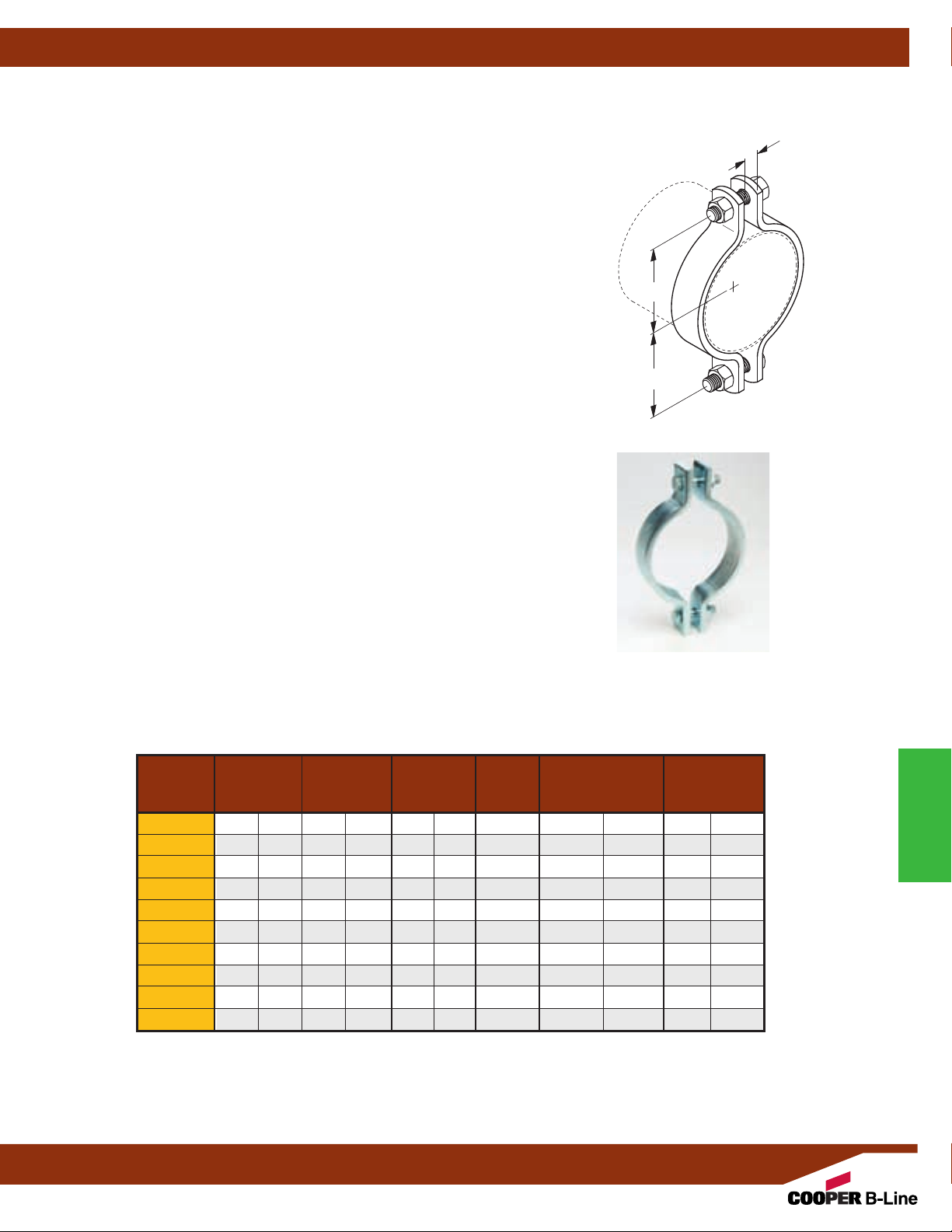
B3141 - A.W.W.A. Pipe Clamp (TOLCO Fig. 4CI)
Pipe Clamps
Size Range: 4" (100mm) thru 24" (600mm) pipe
Material: Steel
Function: Recommended for the suspension of flanged or bell and spigot
A.W
.W.A. cast iron or ductile iron pipe. The O.D. of the A.W.W.A. iron pipe is
shown in the data table. Used with B3200 weldless eye nut, B3210 eye rod
or B3211 welded eye rod.
Approvals: Conforms to Federal Specification WW-H-171E & A-A-1192A,
T
ype 4, and Manufacturers Standardization Society ANSI/MSS SP-69 &
SP-58, Type 4.
Maximum Temperature: 650°F
Finish: Plain
Note: Available in Electro-Galvanized and HDG finish or Stainless
Steel materials.
Order By: Figure number, pipe size and finish
(343°C)
A
B
B
Pipe Max. Recommended Approx.
Part O.D. A B Bolt Design Load
No. in. (mm) in. (mm) in. (mm) Size lbs. (kN) lbs. (kg)
B3141-4 4.80" (121.9) 11/8" (28.6) 41/16" (103.2)5/8"-11 1400 (6.23) 860 (390.1)
B3141-6 6.90" (175.2) 11/8" (28.6) 51/16" (128.6)5/8"-11 1400 (6.23) 1060 (480.8)
B3141-8 9.05" (229.9) 11/8" (28.6) 63/16" (157.2)5/8"-11 1400 (6.23) 1230 (557.9)
B3141-10 11.10" (281.9) 11/8" (28.6) 71/4" (184.1)5/8"-11 1400 (6.23) 1430 (648.6)
B3141-12 13.20” (335.3) 11/8" (28.6) 85/16" (211.1)5/8"-11 1400 (6.23) 1630 (739.3)
B3141-14 15.30" (388.6) 13/4" (44.4) 97/8" (250.7)3/4"-10 2000 (8.89) 2300 (1043.3)
B3141-16 17.40" (441.9) 13/4" (44.4) 115/16" (287.3)7/8"-9 2500 (11.12) 3725 (1689.6)
B3141-18 19.50" (495.3) 17/8" (47.6) 129/16" (319.1) 1"-8 3000 (13.34) 4200 (1905.1)
B3141-20 21.60" (548.6) 2" (50.8) 135/8" (346.1) 1"-8 3100 (13.79) 4575 (2075.2)
B3141-24 25.80" (655.3) 2" (50.8) 165/16" (414.3)1/4"-7 4500 (20.01) 6400 (2903.0)
All dimensions in charts and on drawings are in inches. Dimensions shown in parentheses are in millimeters unless otherwise specified.
Wt./100
81
Pipe Clamps
Page 84
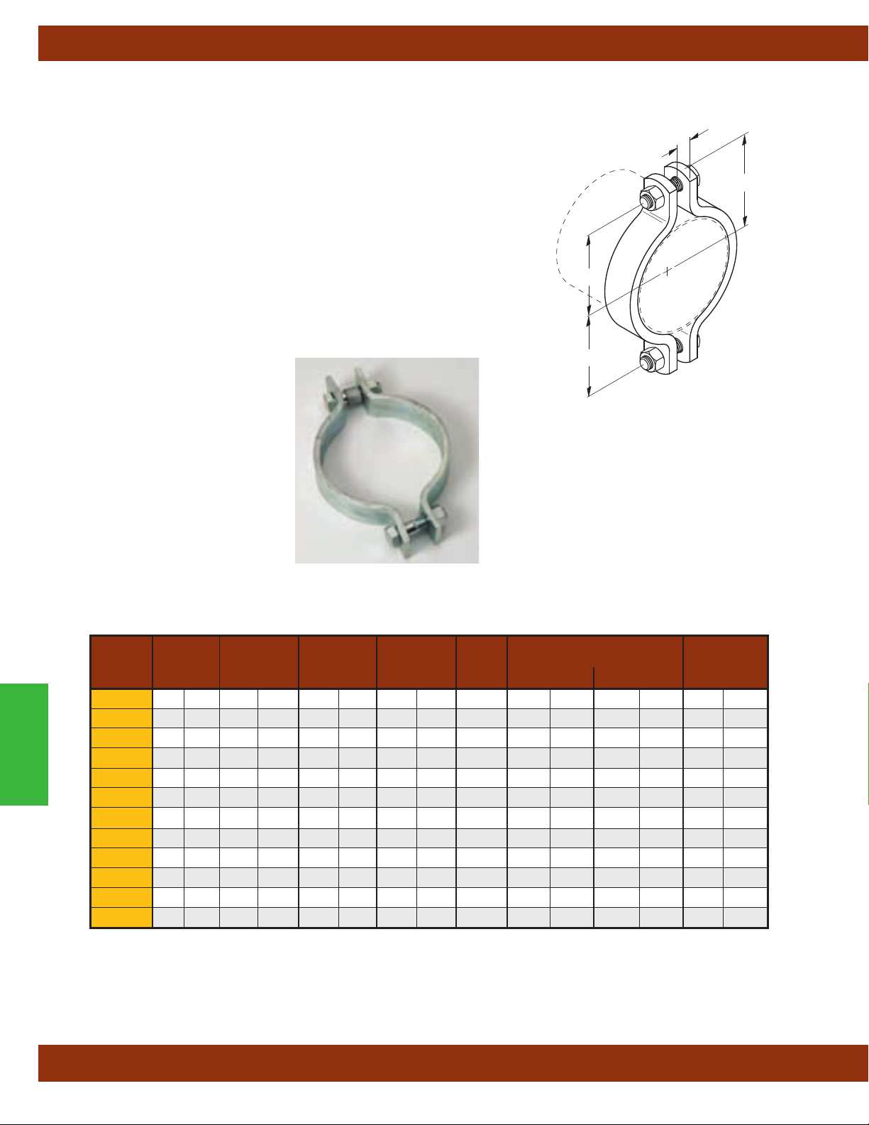
Pipe Clamps
B3142 - Heavy Duty Pipe Clamp (TOLCO Fig. 4H)
Size Range: 3" (80mm) thru 24" (600mm) pipe
Material: Steel
Function: Recommended for the suspension of heavy-duty pipe lines.
(Use with B3200 weldless eye nut, B3210 eye rod or B321
Approvals: Conforms to Federal Specification WW-H-171E & A-A-1192A,
Type 4, and Manufacturers Standardization Society
Type 4.
Maximum Temperature: 650°F
Finish: Plain. Contact Cooper B-Line for alterantive finishes and materials.
Order By: Figure number, pipe size and finish
(343°C)
1 welded eye rod).
ANSI/MSS SP-69 & SP-58,
A
C
B
B
Pipe Clamps
Pipe Max. Design Load Approx.
Part Size A B C Bolt 650°F (343°C) 750°F (399°C) Wt./100
No. in. (mm) in. (mm) in. (mm) in. (mm) Size lbs. (kN) lbs. (kN) lbs. (kg)
B3142-3 3" (80) 1" (25.4) 3" (76.2) 41/8" (104.8)3/4"-10 3370 (14.99) 3005 (13.36) 498 (225.9)
B3142-4 4" (100) 1" (25.4) 311/16" (93.7) 415/16" (125.4)7/8"-9 3515 (15.63) 3135 (13.94) 634 (287.6)
B3142-5 5" (125) 1" (25.4) 45/16" (109.5) 59/16" (141.3)7/8"-9 3515 (15.63) 3135 (13.94) 714 (323.9)
B3142-6 6" (150) 11/8" (28.6) 53/16" (131.8) 611/16" (169.9) 1"-8 4865 (21.64) 4340 (19.30) 1351 (612.8)
B3142-8 8" (200) 11/8" (28.6) 61/4" (158.7) 73/4" (196.8) 1"-8 4865 (21.64) 4340 (19.30) 1573 (713.5)
B3142-10 10" (250) 11/4" (31.7) 77/8" (200.0) 91/2" (241.3) 11/4"-7 6010 (26.73) 5360 (23.84) 2537 (1150.8)
B3142-12 12" (300) 15/8" (41.3) 91/2" (241.3) 115/8" (295.3) 11/2"-6 8675 (38.58) 7740 (34.43) 4300 (1950.5)
B3142-14 14" (350) 15/8" (41.3) 101/8" (257.2) 121/4" (311.1) 11/2"-6 9120 (40.56) 8135 (36.18) 5228 (2371.4)
B3142-16 16" (400) 15/8" (41.3) 113/16" (284.2) 135/16" (338.1) 11/2"-6 9120 (40.56) 8135 (36.18) 5657 (2566.0)
B3142-18 18" (450) 15/8" (41.3) 123/16" (309.6) 145/16" (363.5) 11/2"-6 9150 (40.70) 8160 (36.29) 6914 (3136.2)
B3142-20 20" (500) 15/8" (41.3) 135/16" (338.1) 157/16" (392.1) 11/2"-6 9150 (40.70) 8160 (36.29) 7468 (3387.5)
B3142-24 24" (600) 13/4" (44.4) 153/8" (390.5) 173/4" (450.8) 11/2"-6 9200 (40.92) 8205 (36.49) 12629 (5728.5)
All dimensions in charts and on drawings are in inches. Dimensions shown in parentheses are in millimeters unless otherwise specified.
82
Page 85
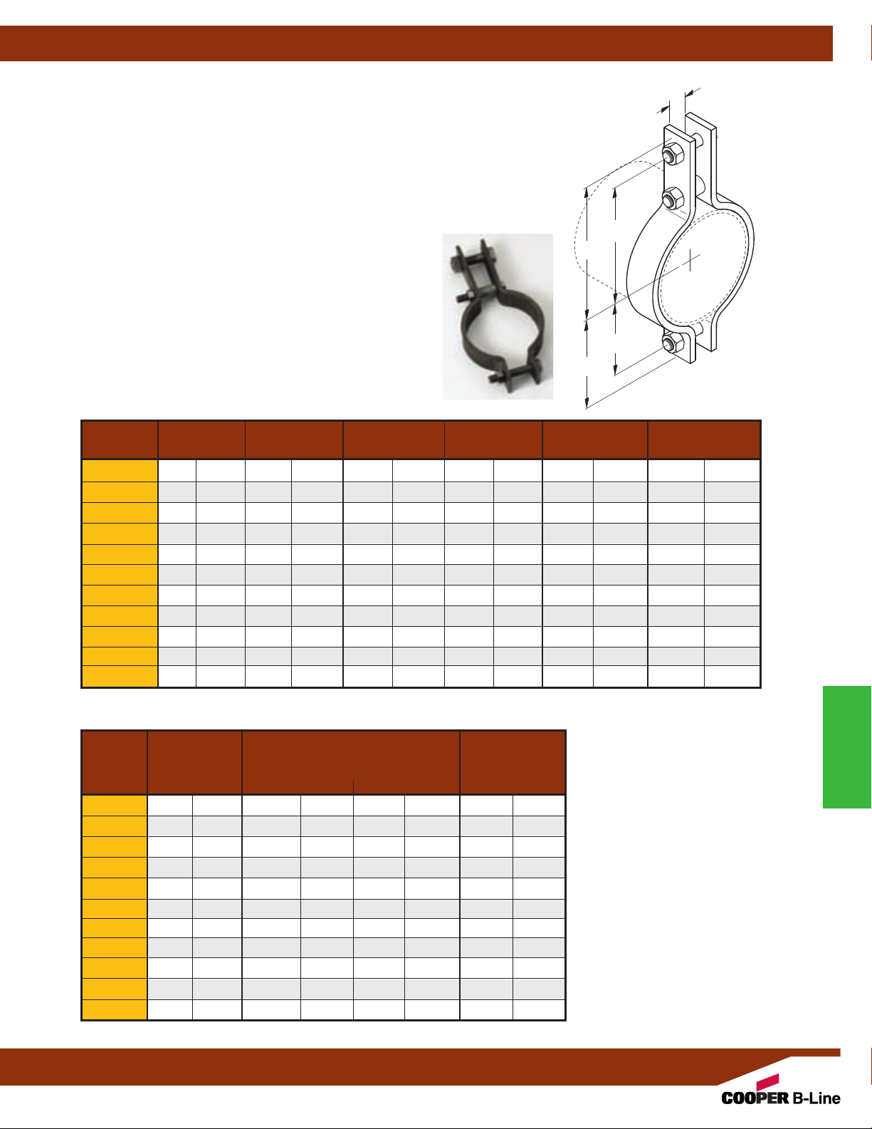
Pipe Clamps
Fig. B3146 - Heavy Duty Double Bolt Pipe Clamp (TOLCO Fig. 5H)
Size Range: 6" (150mm) thru 36" (900mm) pipe.
Material: Steel
Function: Recommended for the suspension of heavy
duty high temperature pipe runs requiring up to 4"
insulation and where flexibility of the clamp may be
necessary. Use with B3200 weldless eye nut, B3210 eye rod or
B3211 welded eye rod.
Approvals: Conforms to Federal Specification
WW-H-171E &
A-A-1192A, Type 3 and Manufacturers
Standardization Society ANSI/MSS SP-69 & SP-58, Type 3.
Maximum Temperature: 750°F
(399°C)
Finish: Plain. Contact Cooper B-Line for alternative finishes
and materials.
Order By: Figure number, pipe size and finish.
Pipe Size A B C D E
Part No. in. (mm) in. (mm) in. (mm) in. (mm) in. (mm) in. (mm)
B3146-6 6" (150) 13/4
" (44.4) 103/16
B3146-8 8" (200) 2" (50.8) 113/8
B3146-10 10" (350) 21/4
B3146-12 12" (300) 21/2
B3146-14 14" (450) 21/2
" (57.1) 131/8
" (63.5) 145/16
" (63.5) 151/2
B3146-16 16" (400) 3" (76.2) 171/8
B3146-18 18" (550) 31/2
B3146-20 20" (500) 31/2
B3146-24 24" (600) 31/2
B3146-30 30" (750) 41/4
B3146-36 36" (900) 41/2
" (88.9) 181/4
" (88.9) 193/4
" (88.9) 223/8
" (107.9) 323/4
" (107.9) 401/4
(101.6mm) of
" (258.8) 815/16
" (288.9) 101/8
" (333.4) 113/8
" (363.5) 129/16
" (393.7) 131/2
" (435.0) 147/8
" (463.5) 161/4
" (501.6) 171/4
" (568.3) 195/16
" (831.8) 281/4
" (1022.3) 343/4
C
B
E
D
" (227.0) 6" (152.4) 43/4
" (257.2) 71/4
" (184.1) 6" (152.4)
" (288.9) 9" (228.6) 71/4
" (319.1) 103/8
" (342.9) 115/8
" (377.7) 131/8
" (412.7) 141/2
" (263.5) 85/8
" (295.3) 95/8
" (333.4) 107/8
" (368.3) 121/2
" (438.1) 16" (406.4) 131/2
" (490.5) 181/2
" (717.5) 243/8
" (882.6) 301/8
" (469.9) 151/2
" (619.1) 197/8
" (765.2) 225/8
" (120.6)
" (184.1)
" (219.1)
" (244.5)
" (276.2)
" (317.5)
" (342.9)
" (393.7)
" (504.8)
" (574.7)
A
Maximum Design Load For
Part No.
Bolt
Size
in. (mm) Lbs. (kN) Lbs. (kN) Lbs. (kg)
Service Temperature
650°F (343
°
C) 750°F (399°C
Approx.
) Wt./100
B3146-6 1" (25.4) 3500 (15.57) 3125 (13.90) 1200 (544.3)
B3146-8 11/8" (28.6) 4800 (21.35) 4285 (19.06) 1850 (839.1)
B3146-10 11/4" (31.7) 5500 (24.46) 4910 (21.84) 3030 (1374.4)
B3146-12 13/8" (34.9) 7000 (31.13) 6250 (27.80) 4200 (1905.1)
B3146-14 11/2" (38.1) 9500 (42.25) 8485 (37.74) 6000 (2721.6)
B3146-16 13/4" (44.4) 10000 (44.48) 8930 (39.72) 8000 (3628.8)
B3146-18 2" (50.8) 13800 (61.38) 12325 (54.82) 11500 (5216.4)
B3146-20 2" (50.8) 15300 (68.05) 13665 (60.78) 14000 (6350.4)
B3146-24 2" (50.8) 16300 (72.50) 14555 (64.74) 19000 (8618.4)
B3146-30
B3146-36
21/4" (57.1) 20500 (91.18) -- (--) 40600 (18416.1)
23/4" (69.8) 28000 (124.54) -- (--) 67800 (30754.1)
All dimensions in charts and on drawings are in inches. Dimensions shown in parentheses are in millimeters unless otherwise specified.
83
Pipe Clamps
Page 86
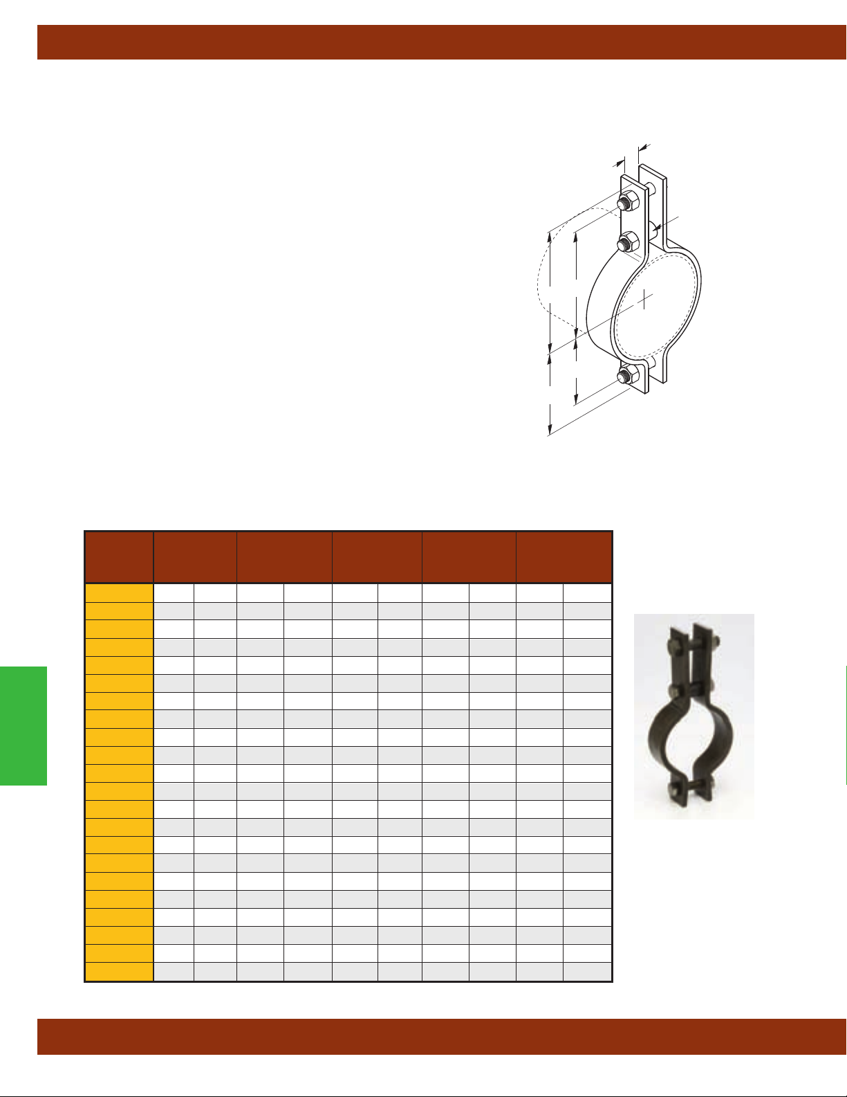
Pipe Clamps
B3144 - Standard Double Bolt Pipe Clamp (TOLCO Fig. 5)
Size Range: — 1/2" (15mm) thru 36" (900mm) pipe.
Material: — Steel
Function: — Recommended for the suspension of pipe requiring up to
4"
(101.6mm) of insulation and where flexibility of the clamp may be
necessary. Use B3200 weldless eye nut, B3210 eye rod or B3211
welded eye rod. Also recommended for the attachment of sway bracing
up to 8"
Approved Seismic Restraint Product Manual.
Approvals: — Conforms to Federal Specification WW-H-171E &
A-A-1
ANSI/MSS SP-69 & SP-58, Type 3. Included in our Seismic Restraints
Catalog approved by the State of California Office of Statewide Health
Planning and Development (OSHPD). For additional load, spacing and
placement information relating to OSHPD projects, please refer to the
Cooper B-Line/T
Maximum Temperature: 750°F
Finish: Plain. Contact Cooper B-Line for alternative finishes and
materials.
Order By: Figure number, pipe size and finish.
(203.2mm). Refer to Cooper B-Line/TOLCO State of California
192A, Type 3 and Manufacturers Standardization Society
OLCO Seismic Restraint Systems Guidelines.
(399°C)
Component of State of
California OSHPD Approved
Seismic Restraints System
C
B
E
D
A
Spacer
B3144-1/2
B3144-3/4
B3144-1 1" (25)
B3144-11/4 11/4" (32)
B3144-11/2 11/2" (40) 1" (25.4) 53/8" (136.5) 41/2" (114.3) 25/8" (66.7)
Pipe Clamps
B3144-2 2" (50) 1" (25.4) 513/16" (147.6) 415/16" (125.4) 215/16" (74.6)
B3144-21/2 21/2" (65) 1" (25.4) 61/8" (155.6) 51/4" (133.3) 31/4" (82.5)
B3144-3 3" (75) 1" (25.4) 63/4" (171.4) 57/8" (149.2) 35/8" (92.1)
B3144-31/2 31/2" (90) 1" (25.4) 73/16" (182.6) 65/16" (160.3) 37/8" (98.4)
B3144-4 4" (100) 1" (25.4) 73/4" (196.8) 65/8" (168.3) 411/16" (119.1)
B3144-5 5" (125) 1" (25.4) 89/16" (217.5) 77/16" (189.5) 55/16" (134.9)
B3144-6 6" (150) 11/2" (38.1) 97/8" (250.8) 81/2" (215.9) 61/8" (155.6)
B3144-8 8" (200) 11/2" (38.1) 11" (279.4) 95/8" (244.5) 75/16" (185.7)
B3144-10 10" (250) 11/2" (38.1) 12" (304.8) 101/2" (266.7) 87/8" (225.4)
B3144-12 12" (300) 11/2" (38.1) 131/8" (333.4) 115/8" (295.3) 915/16" (252.4)
B3144-14 14" (350) 2" (50.8) 145/16" (363.5) 129/16" (319.1) 115/16" (287.3)
B3144-16 16" (400) 2" (50.8) 159/16" (395.3) 1313/16" (350.8) 125/16" (312.7)
B3144-18 18" (450) 2" (50.8) 167/8" (428.6) 151/8" (384.2) 133/8" (339.7)
B3144-20 20" (500) 2" (50.8) 181/4" (463.5) 163/8" (415.9) 151/8" (384.2)
B3144-24 24" (600) 2" (50.8) 207/16" (519.7) 187/16" (468.3) 175/16" (439.7)
B3144-30 30" (750) 21/2" (63.5) 26" (660.4) 23" (584.2) 22" (558.8)
B3144-36 36" (900) 21/2" (63.5) 323/8" (822.2) 287/8" (733.4) 255/8" (650.9)
Pipe
Part Size A B C D
No.
in. (mm) in. (mm) in. (mm) in. (mm) in. (mm)
1
/2" (15)
3
/4" (20)
3
/8" (9.5) 113/16" (46.0) 213/16" (71.4) 11/2" (38.1)
5
/8" (15.9) 3" (76.2) 23/8" (60.2) 111/16" (42.9)
5
/8" (15.9) 31/4" (82.5) 25/8" (66.7) 115/16" (49.2)
5
/8" (15.9) 31/2" (88.9) 27/8" (72.9) 23/16" (58.7)
All dimensions in charts and on drawings are in inches. Dimensions shown in parentheses are in millimeters unless otherwise specified.
84
Page 87

B3144 - Standard Double Bolt Pipe Clamp (TOLCO Fig. 5) cont.
A
Spacer
C
B
E
D
Pipe Clamps
Component of State of
California OSHPD Approved
Seismic Restraints System
Pipe Max. Design Load Approx.
Part Size Bolt Size 650°F (343°C) 750°F (399°C) Wt./100
No. in. (mm) Size lbs. (kN) lbs. (kN) lbs. (kg)
B3144-1/2
B3144-3/4
1
/2" (15)
3
/4" (20)
B3144-1 1" (25)
B3144-11/4 11/4" (32)
B3144-11/2 11/2" (40)
B3144-2 2" (50)
B3144-21/2 21/2" (65)
B3144-3 3" (75)
B3144-31/2 31/2" (90)
B3144-4 4" (100)
B3144-5 5" (125)
B3144-6 6" (150)
B3144-8 8" (200)
3
/8"-16 950 (4.22) -- (--) 73 (33.1)
3
/8"-16 950 (4.22) -- (--) 73 (33.1)
3
/8"-16 950 (4.22) -- (--) 77 (34.9)
3
/8"-16 950 (4.22) -- (--) 79 (35.8)
5
/8"-11 1545 (6.87) 1380 (6.14) 236 (107.0)
5
/8"-11 1545 (6.87) 1380 (6.14) 251 (113.8)
5
/8"-11 1545 (6.87) 1380 (6.14) 274 (124.3)
5
/8"-11 1545 (6.87) 1380 (6.14) 289 (131.1)
5
/8"-11 1545 (6.87) 1380 (6.14) 315 (142.9)
3
/4"-10 2500 (11.12) 2230 (9.92) 745 (337.9)
3
/4"-10 2500 (11.12) 2230 (9.92) 828 (375.6)
7
/8"-9 2865 (12.74) 2555 (11.36) 1261 (572.0)
7
/8"-9 2865 (12.74) 2555 (11.36) 1535 (696.3)
B3144-10 10" (250) 1"-8 3240 (14.41) 2890 (12.85) 2173 (985.7)
B3144-12 12" (300) 1"-8 3240 (14.41) 2890 (12.85) 2404 (1090.4)
B3144-14 14" (350) 11/4"-7 4300 (19.12) 3835 (17.06) 4002 (1815.3)
B3144-16 16" (400) 11/4"-7 4300 (19.12) 3835 (17.06) 4362 (1978.6)
B3144-18 18" (450) 11/4"-7 4300 (19.12) 3835 (17.06) 4935 (2238.5)
B3144-20 20" (500) 13/8"-6 5490 (24.42) 4900 (21.79) 6570 (2980.1)
B3144-24 24" (600) 13/8"-6 4500 (20.01) 4015 (17.86) 7524 (3412.9)
B3144-30 30" (750) 13/8"-6 7500 (33.36) -- (--) 19502 (8846.1)
B3144-36 36" (900) 13/4"-5 10500 (46.70) -- (--) 23488 (10654.1)
Pipe Clamps
All dimensions in charts and on drawings are in inches. Dimensions shown in parentheses are in millimeters unless otherwise specified.
85
Page 88

Pipe Clamps
Fig. 4B - Pipe Clamp for Sway Bracing (Cooper B-Line B386)
Size Range:3/4” (20mm) to 8”
Material: Steel
Function: For bracing pipe against sway and seismic disturbance
Approvals: Underwriter's Laboratories Listed in the USA (UL) and Canada
(cUL) for 2”
(50mm) thru 8” (200mm) pipe. Included in the Seismic Restraints
Catalog approved by the State of California Office of Statewide Health
Planning and Development (OSHPD).
Standard Finish: Plain or Electro-Galvanized. Contact Cooper B-Line for
alternative finishes and materials.
Order By: Figure number and finish.
Installation Instructions: Fig. 4B is the “braced pipe” attachment
component of a longitudinal or lateral sway brace assembly
to be combined with the “bracing pipe” and transitional and structural
attachment component(s) to form a complete bracing assembly. NFPA 13
and/or OSHPD guidelines should be followed.
To Install: Place the Fig. 4B over the pipe to be braced. Attach other
transitional fitting, Fig. 909, 910, or 980.
fitting attachment can pivot for adjustment to proper brace angle.
(200mm)
pipe
. It is intended
Tighten bolts and nuts. Transitional
Component of State of
California OSHPD Approved
Seismic Restraints System
™
C
A
B
D
Shown with two B-Line
Fig. 980’s and Schedule
40 brace pipe.
Fig. 4B - Hanger/Longitudinal Brace
Pipe Size Rod Size B C D Bolt Size Design Load
Part No. in. (mm) A in. (mm) in. (mm) in. (mm) Lbs. (kN) Lbs. (kg)
4B-3/4
3
/4" (20)3/8"-16 1" (25.4) 27/8" (73.0) 25/8" (66.7)5/16"-18 330 (1.47) 56 (3.6)
4B-1 1" (25)3/8"-16 1" (25.4) 31/4" (82.5) 215/16" (74.6)5/16"-18 330 (1.47) 60 (3.6)
Pipe Clamps
4B-11/4 11/4" (32)3/8"-16 1" (25.4) 39/16" (90.6) 31/4" (82.5)5/16"-18 330 (1.47) 74 (4.5)
4B-11/2 11/2" (40)3/8"-16 1" (25.4) 313/16" (96.8) 37/16" (87.3)5/16"-18 330 (1.47) 79 (5.0)
4B-2 2" (50)3/8"-16 11/2" (38.1) 51/8" (130.2) 45/8" (117.5)5/16"-18 440 (1.78) 156 (5.0)
4B-21/2 21/2" (65)1/2"-13 13/4" (44.4) 55/8" (142.9) 53/8" (136.5)3/8"-16 440 (1.78) 176 (5.4)
4B-3 3" (80)1/2"-13 17/8" (47.6) 63/4" (171.4) 61/8" (155.5)3/8"-16 660 (2.93) 198 (6.3)
4B-31/2 31/2" (90)1/2"-13 2" (50.8) 71/4" (184.1) 63/4" (171.4)3/8"-16 660 (2.93) 219 (7.2)
4B-4 4" (100)5/8"-11 2" (50.8) 85/8" (219.1) 71/4" (184.1)2/2"-13 800 (3.56) 288 (8.1)
4B-5 5" (125)5/8"-11 2" (50.8) 97/8" (250.8) 85/16" (211.1)5/8"-11 980 (4.36) 390 (8.1)
4B-6 6" (150)3/4"-10 21/8" (54.0) 1015/16" (277.8) 91/2" (241.3)5/8"-11 980 (4.36) 448 (8.1)
4B-8 8" (200)7/8"-9 21/8" (54.0) 137/16" (341.2) 111/2" (292.1)3/4"-10 1200 (5.34) 691 (8.1)
Cooper B-Line, Inc.’s (“Cooper B-Line”) seismic bracing components are designed to be compatible only with other Cooper B-Line bracing
components, resulting is a listed seismic bracing assembly. Cooper-B-Line’s warranty for seismic bracing components will be the warranty
provided in Cooper B-Line’s standard terms and conditions of sale made available by Cooper B-Line, except that, in addition to the other
exclusions from Cooper B-Line’s warranty, Cooper B-line makes no warranty relating to Cooper B-Line’s seismic bracing components that
are combined with products not provided by Cooper B-Line.
Approx. Wt./100
All dimensions in charts and on drawings are in inches. Dimensions shown in parentheses are in millimeters unless otherwise specified.
86
Page 89

Pipe Clamps
Fig. B3148 - Offset Pipe Clamp (TOLCO Fig. 7)
Size Range:1/2" (15mm) thru 12" (300mm) pipe
Material: Steel
Function: Recommended for support of pipe lines running at a
definite distance from the wall or floor of a building or structure.
Maximum Temperature: — 650°F
Finish: Plain. Contact Cooper B-Line for alterantive finishes and
materials.
Note: Special “B” dimensions available on request,
consult factory.
Order By: Figure number, pipe size and finish
Pipe Size A Bolt Size B C H
Part No.
in. (mm) in. (mm) in. (mm) in. (mm) Lbs. (kN) Lbs. (kg)
B3148-1/21/2" (15) 27/16" (61.9)
B3148-3/43/4" (20) 21/2" (63.5)
B3148-1 1" (25) 25/8" (66.7)
B3148-11/4 11/4" (32) 23/4" (69.8)
B3148-11/2 11/2" (40) 3" (76.2)
B3148-2 2" (50) 33/16" (81.0)
B3148-21/2 21/2" (65) 37/16" (87.3)
B3148-3 3" (80) 33/4" (95.2)
B3148-31/2 31/2" (90) 4" (101.6)
B3148-4 4" (100) 41/4" (107.9)
B3148-6 6" (150) 55/16" (134.9)
B3148-8 8" (200) 65/16" (160.3)
B3148-10 10" (250) 73/8" (187.3)
B3148-12 12" (300) 83/8" (212.7)
(343°C)
3
/8"-16 513/16" (147.6)7/16" (11.1) 190 (.84) 107 (48.5)
3
/8"-16 515/16" (150.8)7/16" (11.1) 190 (.84) 109 (49.4)
3
/8"-16 61/4" (158.7)7/16" (11.1) 190 (.84) 116 (52.6)
3
/8"-16 611/16" (169.9)7/16" (11.1) 190 (.84) 126 (57.1)
3
/8"-16615/16" (176.2)7/16" (11.1) 190 (.84) 134 (60.8)
3
/8"-16 85/16" (211.1)7/16" (11.1) 420 (1.87) 191 (86.6)
3
/8"-16 87/8" (225.4)7/16" (11.1) 420 (1.87) 209 (94.8)
3
/8"-16 91/2" (241.3)7/16" (11.1) 420 (1.87) 232 (105.3)
3
/8"-16101/16" (255.6)7/16" (11.1) 420 (1.87) 250 (113.4)
1
/2"-13 109/16" (268.3)9/16" (14.3) 610 (2.71) 370 (167.8)
1
/2"-13 143/8" (365.1)9/16" (14.3) 870 (3.87) 650 (294.8)
1
/2"-13 167/16" (417.5)9/16" (14.3) 870 (3.87) 787 (357.0)
3
/4"-10 211/2" (546.1)13/16" (20.6) 925 (4.11) 1238 (561.5)
3
/4"-10 247/8" (631.8)13/16" (20.6) 1225 (5.45) 2100 (952.5)
Design Load
C
Design Load
Bolts and Nuts
Included
Bolt Size
B
A
H
2 Holes
Approx. Wt./100
Pipe Clamps
All dimensions in charts and on drawings are in inches. Dimensions shown in parentheses are in millimeters unless otherwise specified.
87
Page 90
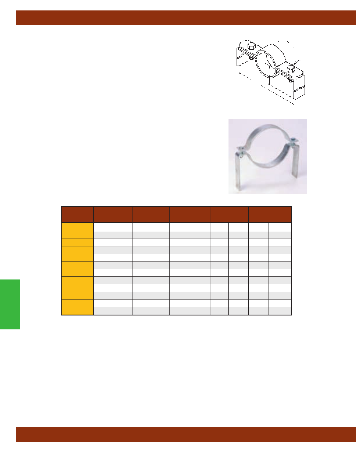
Pipe Clamps
B3149 - Extended Pipe Clamp (TOLCO Fig. 8)
Size Range:3/4" (20mm) thru 8" (200mm) pipe
Material: Steel
Function: For suspending or supporting piping runs where the
pipe cannot be determined until installation. Field modify to suit
conditions.
Maximum Temperature: 650°F
Finish: Plain. Contact Cooper B-Line for alternative finishes and
materials.
Note: Special “B” dimensions available on request, consult factory.
Order By: Figure number, pipe size and finish
(343°C)
Bolt Size
B
A
Pipe Clamps
Part No.
B3149-3/4
in. (mm) in. (mm) in. (mm) in. (mm)
3
/4" (20)
B3149-1 1" (25)
B3149-11/4 11/4" (32)
B3149-11/2 11/2" (40)
B3149-2 2" (50)
B3149-21/2 21/2" (65)
B3149-3 3" (75)
B3149-31/2 31/2" (90)
B3149-4 4" (100)
B3149-5 5" (125)
B3149-6 6" (150)
B3149-8 8" (200)
Pipe Size Bolt Size A B Approx. Wt./100
3
/8"-16" 47/16" (112.7) 12" (304.8) 225 (102.0)
3
/8"-16" 411/16" (119.1) 12" (304.8) 230 (104.3)
3
/8"-16" 5" (127.0) 12" (304.8) 235 (106.6)
3
/8"-16" 51/4" (133.3) 12" (304.8) 240 (108.8)
1
/2"-13" 6" (152.4) 12" (304.8) 345 (156.5)
1
/2"-13" 71/4" (184.1) 12" (304.8) 360 (163.3)
1
/2"-13" 77/8" (200.0) 12" (304.8) 375 (170.1)
1
/2"-13" 83/8" (212.7) 12" (304.8) 390 (176.9)
1
/2"-13" 91/4" (234.9) 12" (304.8) 500 (226.8)
1
/2"-13" 101/2" (266.7) 12" (304.8) 545 (247.2)
5
/8"-11" 121/2" (317.5) 12" (304.8) 870 (394.6)
5
/8"-11" 145/8" (371.5) 12" (304.8) 980 (444.5)
All dimensions in charts and on drawings are in inches. Dimensions shown in parentheses are in millimeters unless otherwise specified.
88
Page 91

B3180FL - Flush Mount Pipe Strap (TOLCO Fig. 20S)
Size Range:1/2" (15mm) thru 8" (200mm) pipe
Material: Steel
Function: Recommended for supporting pipe with fittings
vertically or horizontally to walls or ceiling. Supports pipe
fglush with the mounting surface.
Approvals: Conforms to Federal Specification WW-H-171E
&
A-A-1192A, Type 26 and Manufacturers Standardization
Society ANSI/MSS SP-69 & SP-58, Type 26.
Finish: Plain
Note: Available in Electro-Galvanized and
HDG finish or Stainless Steel materials.
Order By: Figure number, pipe size and material/finish
Pipe Clamps
A
C
B
D
Part Pipe Size A B C D Hole Size Max. Rec. Load Approx. Wt./100
No. in. (mm) in. (mm) in. (mm) in. (mm) in. (mm) in. (mm) lbs. (kN) lbs. (kg)
B3180FL-1/21/2" (15) 41/8" (104.8)5/16" (7.9) 27/8" (73.0)3/4" (19.0)7/16 (11.1) 410 (1.82) 21 (9.5)
B3180FL-3/43/4" (20) 45/16" (109.5)7/16" (11.1) 3" (76.2)15/16" (23.8) 7/16" (11.1) 410 (1.82) 24 (10.9)
B3180FL-1 1" (25) 49/16" (115.9)9/16" (14.3) 33/8" (85.7) 11/8" (28.6) 7/16" (11.1) 410 (1.82) 26 (11.8)
B3180FL-11/4 11/4" (32) 415/16" (125.4)11/16" (17.5) 33/4" (95.2) 11/2" (38.1) 7/16" (11.1) 410 (1.82) 30 (13.6)
B3180FL-11/2 11/2" (40) 53/16" (131.8)13/16" (20.6) 41/4" (107.9) 15/8" (41.3) 7/16" (11.1) 410 (1.82) 33 (14.9)
B3180FL-2 2" (50) 53/4" (146.0) 11/16" (27.0) 43/4" (120.6) 21/4" (57.1) 7/16" (11.1) 410 (1.82) 38 (17.2)
B3180FL-21/2 21/2" (65) 61/4" (158.7) 19/16" (39.7) 51/4" (133.3) 23/4" (69.8) 7/16" (11.1) 610 (2.71) 102 (46.2)
B3180FL-3 3" (75) 67/8" (174.6) 15/8" (41.3) 57/8" (149.2) 33/8" (85.7) 7/16" (11.1) 610 (2.71) 118 (53.5)
B3180FL-31/2 31/2" (90) 7
3/
8" (187.3) 1
7
/8" (47.6) 63/8" (161.9) 37/8" (98.3) 7/16" (11.1) 610 (2.71) 130 (58.9)
B3180FL-4 4" (100) 83/8" (212.7) 21/8" (53.9) 7" (177.8) 43/8" (111.1) 9/16" (14.3) 725 (3.22) 159 (72.1)
B3180FL-5 5" (125) 97/16" (239.7) 25/8" (66.7) 77/8" (200.0) 53/8" (136.5) 9/16" (14.3) 725 (3.22) 191 (86.6)
B3180FL-6 6" (150) 101/2" (266.7) 33/16" (80.9) 87/8" (225.4) 67/16" (163.5) 9/16" (14.3) 725 (3.22) 234 (106.1)
B3180FL-8 8" (200) 14" (355.6) 41/4" (107.9) 111/2" (292.1) 83/8" (212.7) 11/16" (17.5) 900 (4.00) 446 (202.3)
All dimensions in charts and on drawings are in inches. Dimensions shown in parentheses are in millimeters unless otherwise specified.
Pipe Clamps
89
Page 92
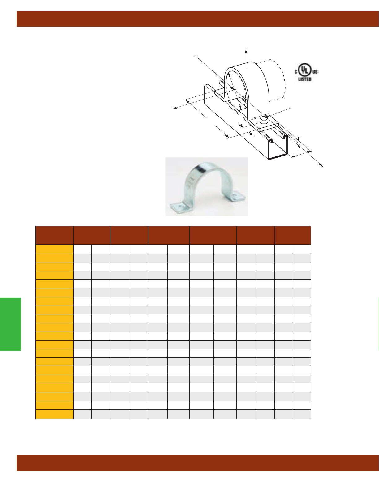
Pipe Clamps
Fig. B2400 - Standard Pipe Strap (TOLCO Fig. 2STR)
Size Range:1/2" (15mm) thru 24" (600mm) pipe
Material: Steel
Function: Designed for supporting pipe runs from
strut supports.
Approvals:
B2400Specification WW-H-171E & A-A-1192A, Type 26 and
Manufacturers Standardization Society ANSI/MSS
SP-69 & SP-58, Type 26.
Finish: Electro-Galvanized. Contact Cooper
B-Line for alternative finishes and materials.
Order By: Figure number, pipe size and finish
Note: Ductile iron sizes available.
Special “B” dimensions available on request,
consult factory
Underwriters Laboratories Listed for
3
/4" thru B2400-8".
Conforms to Federal
.
Design
Load 3
Design Load 1
Pipe Size
Bolt Size
A
C
T
B
W
Design Load 2
Part No. Pipe Size A BCTW
B2400-1/2
B2400-3/4
B2400-1 1” (25)5/16” (7.9)7/16” (11.1) 317/32” (89.7) 10 Ga. (3.4) 15/8” (41.3)
B2400-11/4 11/4” (32)5/16” (7.9)7/16” (11.1) 33/4” (95.2) 10 Ga. (3.4) 15/8” (41.3)
B2400-11/2 11/2” (40)5/16” (7.9)7/16” (11.1) 41/16” (103.2) 10 Ga. (3.4) 15/8” (41.3)
B2400-2 2” (50)7/16” (11.1)11/16” (17.4) 521/32” (143.6)
B2400-21/2 21/2” (65)7/16” (11.1)11/16” (17.4) 65/32” (156.3)
Pipe Clamps
B2400-3 3” (80)7/16” (11.1)11/16” (17.4) 625/32” (172.2)
B2400-31/2 31/2” (90)7/16” (11.1)11/16” (17.4) 79/32” (184.9)
B2400-4 4” (100)9/16” (14.3)11/16” (17.4) 725/32” (197.6)
B2400-5 5” (125)9/16” (14.3)11/16” (17.4) 87/8” (225.4)
B2400-6 6” (150)9/16” (14.3)11/16” (17.4) 915/16” (252.4)
B2400-8 8” (200)9/16” (14.3)11/16” (17.4) 1131/32” (304.0)
B2400-10 10” (250)9/16” (14.3)11/16” (17.4) 14” (355.6)
B2400-12 12” (300)9/16” (14.3)11/16” (17.4) 16” (406.4)
B2400-14 14” (350)15/16” (23.8) 15/16” (33.3) 203/8” (517.5)
B2400-16 16” (400)15/16” (23.8) 15/16” (33.3) 223/8” (568.3)
B2400-18 18” (450)15/16” (23.8) 15/16” (33.3) 261/8” (663.6)
B2400-20 20” (500)15/16” (23.8) 15/16” (33.3) 281/8” (714.4)
B2400-24 24” (600)15/16” (23.8) 15/16” (33.3) 321/8” (816.0)
in. (mm) in. (mm) in. (mm) in. (mm) in. (mm) in. (mm)
1
/2” (15)5/16” (7.9)7/16” (11.1) 213/16” (71.4) 10 Ga. (3.4) 15/8” (41.3)
3
/4” (20)5/16” (7.9)7/16” (11.1) 3” (76.2) 10 Ga. (3.4) 15/8” (41.3)
1
/4” (6.3) 15/8” (41.3)
1
/4” (6.3) 15/8” (41.3)
1
/4” (6.3) 15/8” (41.3)
1
/4” (6.3) 15/8” (41.3)
1
/4” (6.3) 15/8” (41.3)
1
/4” (6.3) 15/8” (41.3)
1
/4” (6.3) 15/8” (41.3)
1
/4” (6.3) 15/8” (41.3)
1
/4” (6.3) 15/8” (41.3)
1
/4” (6.3) 15/8” (41.3)
3
/8” (9.5) 13/4” (44.4)
3
/8” (9.5) 13/4” (44.4)
1
/2” (12.7) 13/4” (44.4)
1
/2” (12.7) 13/4” (44.4)
1
/2” (12.7) 13/4” (44.4)
All dimensions in charts and on drawings are in inches. Dimensions shown in parentheses are in millimeters unless otherwise specified.
90
Page 93
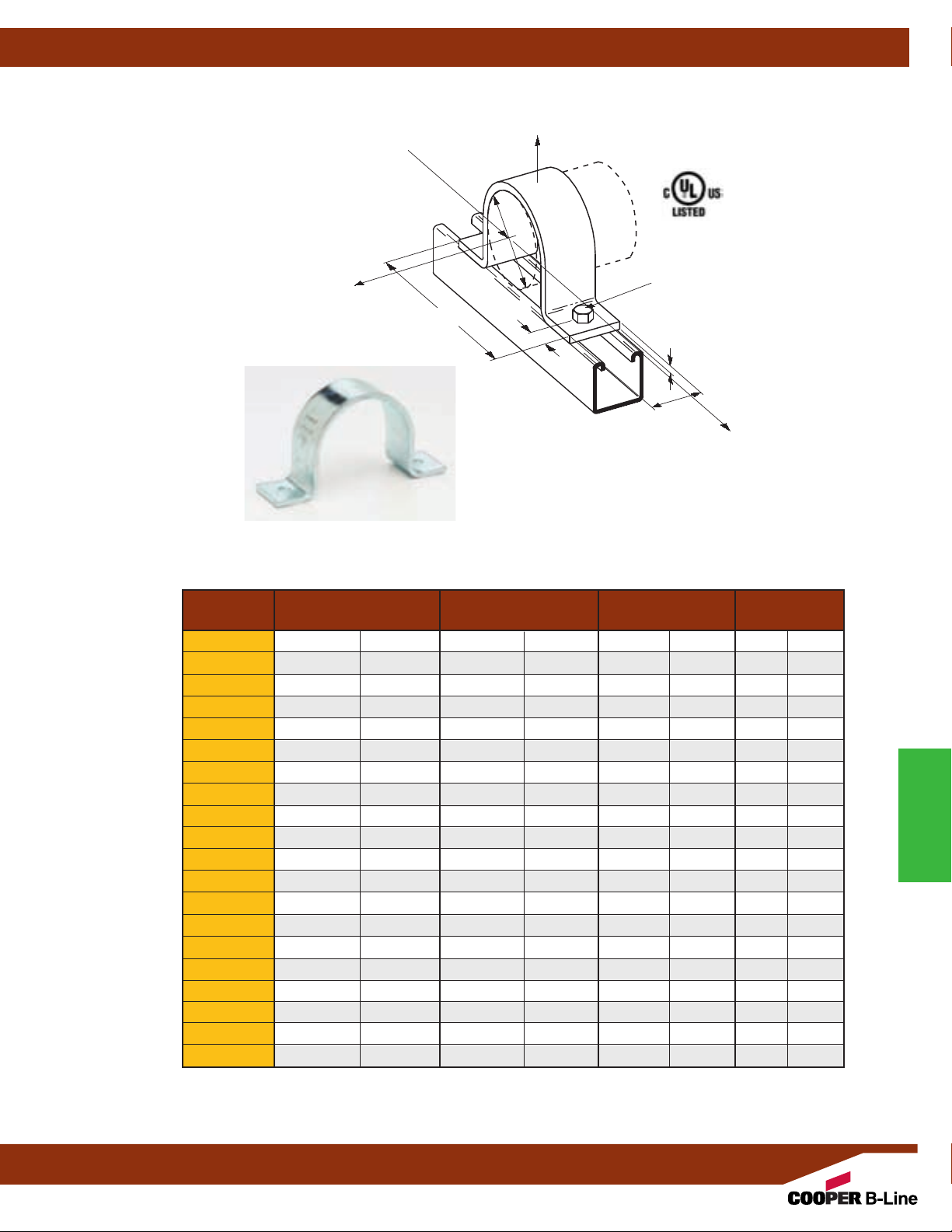
Fig. B2400 - Standard Pipe Strap (TOLCO Fig. 2STR) Cont.
Design Load 1
Pipe Size
Design
Load 3
C
Pipe Clamps
Bolt Size
A
T
B
W
Design Load 2
Part No. Design Load 1 Design Load 2 Design Load 3 Approx. Wt./100
Lbs. (kN) Lbs. (kN) Lbs. (kN) Lbs. (kg)
B2400-1/2 600 (2.67) 150 (.67) 105 (.47) 23 (10.4)
B2400-3/4 600 (2.67) 150 (.67) 105 (.47) 26 (11.8)
B2400-1 600 (2.67) 150 (.67) 120 (.53) 31 (14.0)
B2400-11/4 600 (2.67) 150 (.67) 120 (.53) 36 (16.3)
B2400-11/2 600 (2.67) 150 (.67) 120 (.53) 39 (17.7)
B2400-2 1200 (5.34) 480 (2.14) 180 (.80) 93 (42.2)
B2400-21/2 1200 (5.34) 480 (2.14) 180 (.80) 106 (48.1)
B2400-3 1200 (5.34) 480 (2.14) 300 (1.33) 132 (59.9)
B2400-31/2 1200 (5.34) 480 (2.14) 300 (1.33) 151 (68.5)
B2400-4 1500 (6.67) 600 (2.67) 450 (2.00) 160 (72.6)
B2400-5 1500 (6.67) 600 (2.67) 450 (2.00) 192 (87.1)
B2400-6 1500 (6.67) 600 (2.67) 450 (2.00) 219 (99.3)
B2400-8 2000 (8.90) 800 (3.56) 600 (2.67) 297 (134.7)
B2400-10 2000 (8.90) 800 (3.56) 600 (2.67) 465 (210.9)
B2400-12 2000 (8.90) 800 (3.56) 600 (2.67) 560 (254.0)
B2400-14 2000 (8.90) 800 (3.56) 600 (2.67) 761 (345.2)
B2400-16 2000 (8.90) 800 (3.56) 600 (2.67) 861 (390.5)
B2400-18 2000 (8.90) 800 (3.56) 600 (2.67) 1297 (588.3)
B2400-20 2000 (8.90) 800 (3.56) 600 (2.67) 1426 (646.8)
B2400-24 2000 (8.90) 800 (3.56) 600 (2.67) 1682 (762.9)
Pipe Clamps
All dimensions in charts and on drawings are in inches. Dimensions shown in parentheses are in millimeters unless otherwise specified.
91
Page 94

Pipe Clamps
B3180 - Standard Pipe Strap (TOLCO Fig. 20)
Size Range:1/2" (15mm) thru 8" (200mm) pipe
Material: Steel
Function: Recommended for supporting pipe with fittings
vertically or horizontally to walls or ceiling.
Approvals: Conforms to Federal Specification WW-H-171E &
A-A-1
192A, Type 26 and Manufacturers Standardization Society
ANSI/MSS SP-69 & SP-58, Type 26.
Finish: Plain
Note: Available in Electro-Galvanized and
HDG finish or Stainless Steel materials.
Order By: Figure number, pipe size and material/finish
A
C
B
D
B3180-1/2
B3180-3/4
Pipe Clamps
B3180-1 1" (25) 49/16" (115.9)7/8" (22.2) 33/8" (85.7) 11/2" (38.1) 7/16" (11.1) 410 (1.82) 26 (11.8)
B3180-11/4 11/4" (32) 415/16" (125.4) 1" (25.4) 33/4" (95.2) 17/8" (47.6) 7/16" (11.1) 410 (1.82) 30 (13.6)
B3180-11/2 11/2" (40) 53/16" (131.8) 13/16" (30.2) 41/4" (107.9) 21/8" (54.6) 7/16" (11.1) 410 (1.82) 33 (14.9)
B3180-2 2" (50) 53/4" (146.0) 17/16" (36.5) 43/4" (120.6) 25/8" (66.7) 7/16" (11.1) 410 (1.82) 38 (17.2)
B3180-21/2 21/2" (65) 61/4" (158.7) 111/16" (42.9) 51/4" (133.3) 31/8" (79.4) 7/16" (11.1) 610 (2.71) 102 (46.2)
B3180-3 3" (75) 67/8" (174.6) 2" (50.8) 57/8" (149.2) 33/4" (95.2) 7/16" (11.1) 610 (2.71) 118 (53.5)
B3180-31/2 31/2" (90) 7
B3180-4 4" (100) 83/8" (212.7) 21/2" (63.5) 7" (177.8) 43/4" (120.6) 9/16" (14.3) 725 (3.22) 159 (72.1)
B3180-5 5" (125) 97/16" (239.7) 31/16" (77.8) 77/8" (200.0) 513/16" (147.6) 9/16" (14.3) 725 (3.22) 191 (86.6)
B3180-6 6" (150) 101/2" (266.7) 35/8" (92.1) 87/8" (225.4) 67/8" (174.6) 9/16" (14.3) 725 (3.22) 234 (106.1)
B3180-8 8" (200) 14" (355.6) 45/8" (117.5) 111/2" (292.1) 9" (228.6) 11/16" (17.5) 900 (4.00) 446 (202.3)
Part Pipe Size A B C D Hole Size Max. Rec. Load Approx. Wt./100
No. in. (mm) in. (mm) in. (mm) in. (mm) in. (mm) in. (mm) lbs. (kN) lbs. (kg)
1
/2" (15) 37/8" (98.4)3/4" (19.0) 31/16" (77.8)15/32" (11.9)7/16 (11.1) 410 (1.82) 16 (7.2)
3
/4" (20) 4" (101.6)13/16" (20.6) 31/8" (79.4) 15/16" (33.3) 7/16" (11.1) 410 (1.82) 21 (9.5)
3/
8" (187.3) 2
All dimensions in charts and on drawings are in inches. Dimensions shown in parentheses are in millimeters unless otherwise specified.
1
/4" (57.1) 63/8" (161.9) 41/4" (107.9) 7/16" (11.1) 610 (2.71) 130 (58.9)
92
Page 95
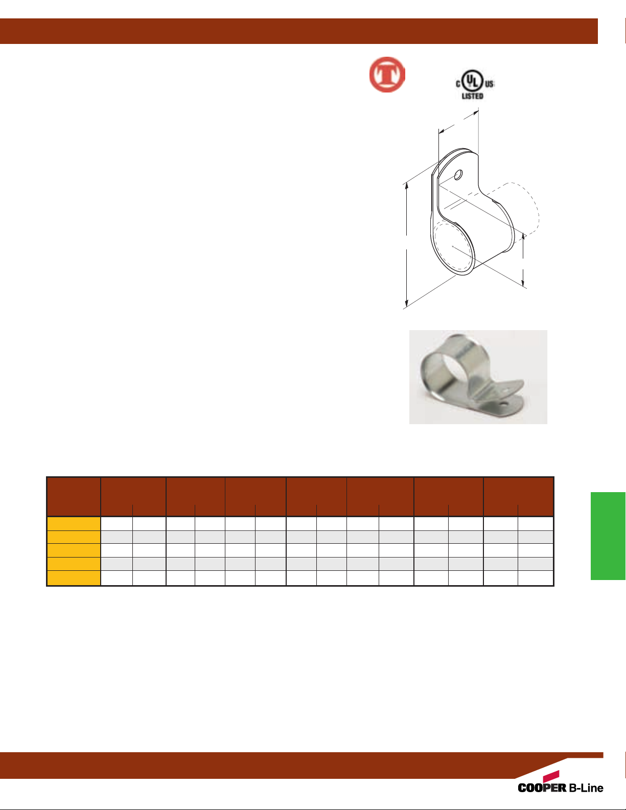
Fig. 22 - Hanger for CPVC Plastic Pipe
Single Fastener Strap
Size Range:3/4" (20mm) thru 2" (50mm) CPVC pipe
Material: Pre-Galvanized Steel
Function: Intended to perform as a hanger to support CPVC piping used
in automatic fire sprinkler systems. The product acts as a hanger when tab
is upward and the fastener screw is in the horizontal position. Fig. 22 can
be installed on the top of a beam, but in this situation acts as a guide to the
piping which is supported by the beam itself. It is not intended to support
CPVC pipe from under a flat horizontal surface, such as a ceiling.
Approvals: Underwriters Laboratories Listed in the USA (UL) and Canada
(cUL) to support fire sprinkler piping. May be installed in wood using
fasteners supplied with product, or into minimum 20 gauge
1
(1)
/4" x 1" tek type screw. Meets and exceeds the requirements of NFPA 13,
13R and 13D.
Features: Fig. 22 incorporates features which protect the pipe and ease
installation.
surface. It is easily attached to the building structure using the special UL
Listed hex head self threading screw* furnished with the product. It is
recommended that rechargeable electric drills fitted with a hex socket
attachment to be used as installation tools. No impact tools (such as a
hammer) are allowed. Damage has been known to result from installations
using impact type tools. No pre-drilling of a pilot hole in wood is
required.
Finish: Pre-Galvanized
Order By: Figure number and CPVC pipe size.
* Hardened hex head self threading screw is furnished with the
product and is the minimum fastener size acceptable.
The flared edge design protects CPVC pipe from any rough
(Cooper B-Line B3181)
(0.9mm) steel using
Pipe Clamps
™
C
A
B
CPVC Max. Hanger Fastener Hex Approx.
Pipe Size A B C Spacing Head Size Wt./100
Part No.
22-3/4
in. (mm) in. (mm) in. (mm) in. (mm) Ft. (m) in. (mm) Lbs. (kg)
3
/4" (20) 27/16" (61.9) 15/16" (33.3) 13/16" (30.2) 51/2 (1.67)
22-1 1" (25) 211/16" (68.3) 17/16" (36.5) 13/16" (30.2) 6 (1,83)
22-11/4 11/4" (32) 31/16" (77.8) 15/8" (42.3) 13/16" (30.2) 61/2 (1.98)
22-11/2 11/2" (40) 35/16" (84.1) 13/4" (44.4) 13/16" (30.2) 7 (2.13)
22-2 2" (50) 33/4" (95.2) 21/8" (54.6) 13/16" (30.2) 8 (2.44)
All dimensions in charts and on drawings are in inches. Dimensions shown in parentheses are in millimeters unless otherwise specified.
93
5
/16" (7.9) 9 (4.1)
5
/16" (7.9) 9 (4.1)
5
/16" (7.9) 11 (5.0)
5
/16" (7.9) 12 (5.4)
5
/16" (7.9) 15 (6.8)
Pipe Clamps
Page 96
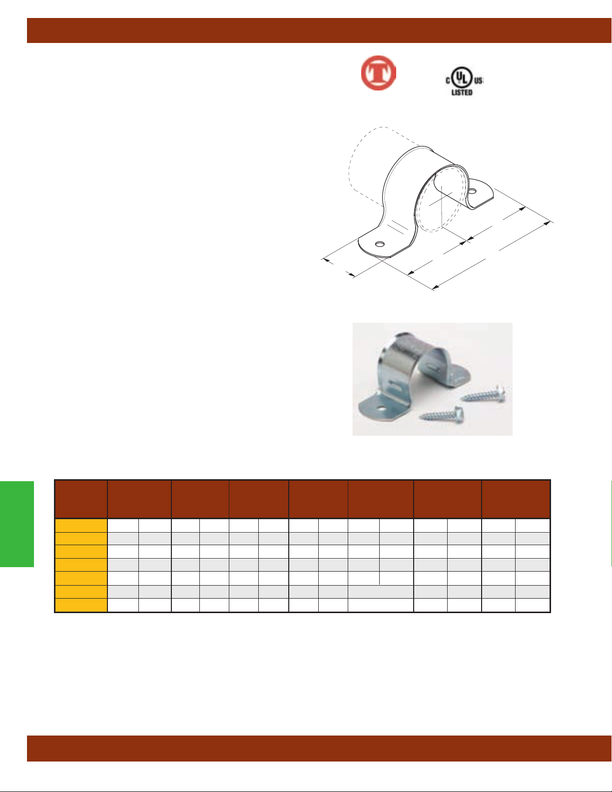
Pipe Clamps
Fig. 23 - Hanger for CPVC Plastic Pipe
Double Fastener Strap (Cooper B-Line B3182)
Size Range:3/4" (20mm) thru 3" (80mm) CPVC pipe
Material: Pre-Galvanized Steel
Function: Intended to perform as a hanger to support CPVC piping
used in automatic fire sprinkler systems. Fig. 23 can be installed
on the top, bottom or side of a beam.
Approvals: Underwriters Laboratories Listed in the USA (UL)
and Canada (cUL) sizes
sprinkler piping. May be installed in wood using fasteners supplied
with product, or into minimum 20 gauge
1" tek type screw. Meets and exceeds the requirements of NFPA 13,
13R and 13D.
Features: Fig. 23 incorporates features which protect the pipe
and ease installation.
pipe from any rough surface. It also incorporates snap restrainers
allowing easier and faster installation. Easily attaches to the building
structure using the two UL Listed hex head self threading screws*
furnished with the product. It is recommended that rechargeable
electric drills fitted with a hex socket attachment be used as
installation tools. No impact tools (such as a hammer) are allowed.
Damage has been known to result from installations using impact
type tools. No pre-drilling of a pilot hole in wood is required.
Finish: Pre-Galvanized
Order By: Figure number and pipe size
* Hardened hex head self threading screw is furnished with the
product and is the minimum fastener size acceptable.
3
/4" (20mm) thru 2" (50mm) to support fire
(0.9mm) steel using (2)
1
/4" x
The flared edge design protects the CPVC
™
B
A
B
C
Pipe Clamps
23-3/4
23-1 1" (25) 33/8" (85.7) 111/16" (42.9) 13/16" (30.2) 6 (1,83)
23-11/4 11/4" (32) 43/16" (106.4) 23/32" (53.1) 13/16" (30.2) 61/2 (1.98)
23-11/2 11/2" (40) 47/16" (112.7) 27/32" (56.3) 13/16" (30.2) 7 (2.13)
23-2 2" (50) 47/8" (123.8) 27/16" (61.9) 13/16" (30.2) 8 (2.44)
23-21/2 21/2" (65) 109/32" (261.1) 211/16" (68.3) 13/16" (30.2) Consult Factory
23-3 3" (80) 117/8" (301.6) 4" (101.6) 13/16" (30.2) Consult Factory
CPVC Max. Hanger Fastener Hex Approx.
Pipe Size A B C Spacing Head Size Wt./100
Part No.
All dimensions in charts and on drawings are in inches. Dimensions shown in parentheses are in millimeters unless otherwise specified.
in. (mm) in. (mm) in. (mm) in. (mm) Ft. (m) in. (mm) Lbs. (kg)
3
/4" (20) 31/8" (79.4) 19/16" (39.7) 13/16" (30.2) 51/2 (1.67)
5
/16" (7.9) 9 (4.1)
5
/16" (7.9) 9 (4.1)
5
/16" (7.9) 11 (5.0)
5
/16" (7.9) 12 (5.4)
5
/16" (7.9) 15 (6.8)
5
/16" (7.9) 22 (10.0)
5
/16" (7.9) 25 (11.3)
94
Page 97
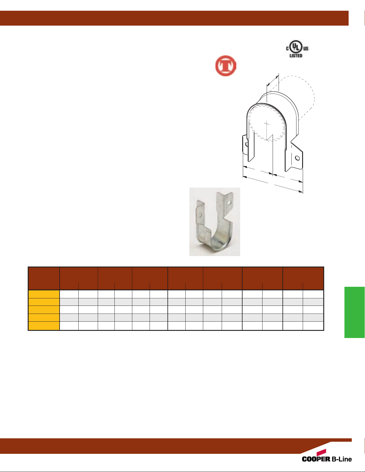
Fig. 24 - Hanger for CPVC Plastic Pipe
Double Fastener Strap Side Mounted (Cooper B-Line B3183)
Size Range:3/4" (20mm) thru 2" (50mm) CPVC pipe
Material: Pre-Galvanized Steel
Function: Intended to perform as a hanger to support CPVC piping used in
automatic fire sprinkler systems. Can be installed on the top or on the bottom
of a beam.
Approvals: Underwriters Laboratories Listed in the USA (UL) and
Canada (cUL) to support fire sprinkler piping. May be installed in wood using
fasteners supplied with product, or into minimum 20 gauge
using (2)
1
/4" x 1" tek type screws. Meets and exceeds the requirements of
NFPA 13, 13R and 13D.
Features: Fig. 24 incorporates features which protect the pipe and
ease installation.
The flared edge design protects the CPVC pipe from
any rough surface. Easily attaches to the building structure using the two
UL Listed hex head self threading screws* furnished with the product. It
is recommended that rechargeable electric drills fitted with a hex socket
attachment be used as installation tools. No impact tools (such as a hammer)
are allowed. Damage has been known to result from installations using
impact type tools. No pre-drilling of a pilot hole in wood is required.
Finish: Pre-Galvanized
Order By: Figure number and pipe size
* Hardened hex head self threading screw is furnished with the
product and is the minimum fastener size acceptable.
(0.912mm) steel
Pipe Clamps
™
C
B
B
A
CPVC Max. Hanger Fastener Hex Approx.
Pipe Size A B C Spacing Head Size Wt./100
Part No.
24-3/4
24-1 1" (25) 25/8" (66.7) 15/16" (33.3) 13/16" (30.2) 6 (1,83)
in. (mm) in. (mm) in. (mm) in. (mm) Ft. (m) in. (mm) Lbs. (kg)
3
/4" (20) 25/16" (58.7) 15/32" (27.8) 13/16" (30.2) 51/2 (1.67)5/16" (7.9) 9 (4.1)
5
/16" (7.9) 9 (4.1)
24-11/4 11/4" (32) 3" (76.2) 11/2" (38.1) 13/16" (30.2) 61/2 (1.98)5/16" (7.9) 11 (5.0)
24-11/2 11/2" (40) 31/4" (82.5) 15/8" (42.3) 13/16" (30.2) 7 (2.13)
24-2 2" (50) 311/16" (93.7) 127/32" (43.6) 13/16" (30.2) 8 (2.44)
All dimensions in charts and on drawings are in inches. Dimensions shown in parentheses are in millimeters unless otherwise specified.
5
/16" (7.9) 12 (5.4)
5
/16" (7.9) 15 (6.8)
Pipe Clamps
95
Page 98
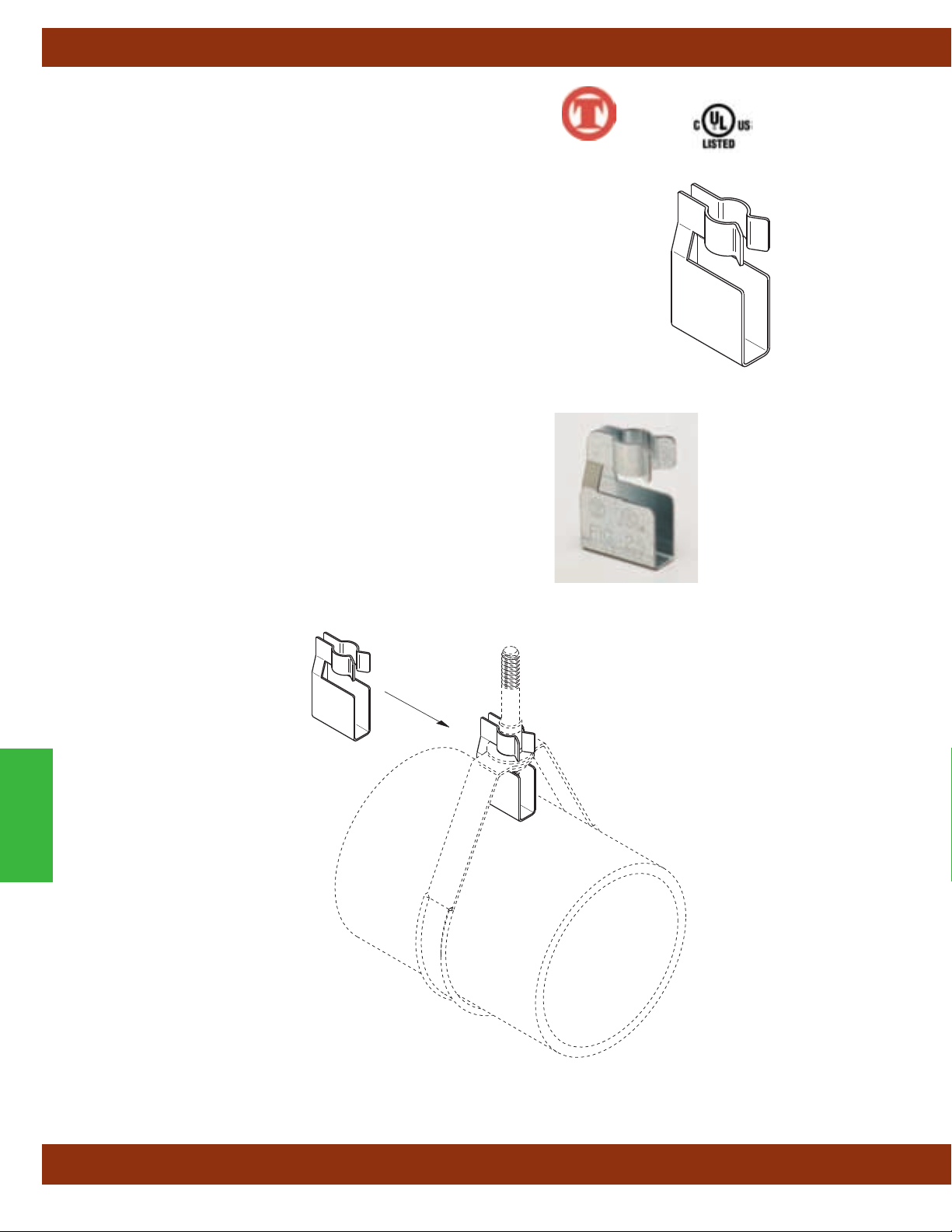
Pipe Clamps
Fig. 25 - Surge Restrainer
Size Range: — One size fits 3/4"
(20mm)
thru 2"
(40mm)
pipe.
Material: — Pre-Galvanized Steel
Function: — Designed to be used in conjunction with Fig. 200 band hangers
to restrict the upward movement of piping as it occurs during sprinkler head
activation or earthquake type activity
. The surge restrainer is easily and
efficiently installed by snapping into a locking position on the band hanger.
This product is intended to satisfy the requirements as indicated in the National
Fire Protection Association NFPA 13, 2010 edition, 9.2.3.4.4.1 and 9.2.3.4.4.4
Can be used to restrain either steel pipe or CPVC plastic Pipe.
Approvals: — Underwriters Laboratories Listed only when used with band
hanger Fig. 200, in the USA (UL) and Canada (cUL).
Finish: Pre-Galvanized
Order By: Figure number and band hanger, size from
3
/4"
(20mm)
thru 2"
(40mm)
.
Patent #5,344,108
™
Pipe Clamps
All dimensions in charts and on drawings are in inches. Dimensions shown in parentheses are in millimeters unless otherwise specified.
96
Page 99
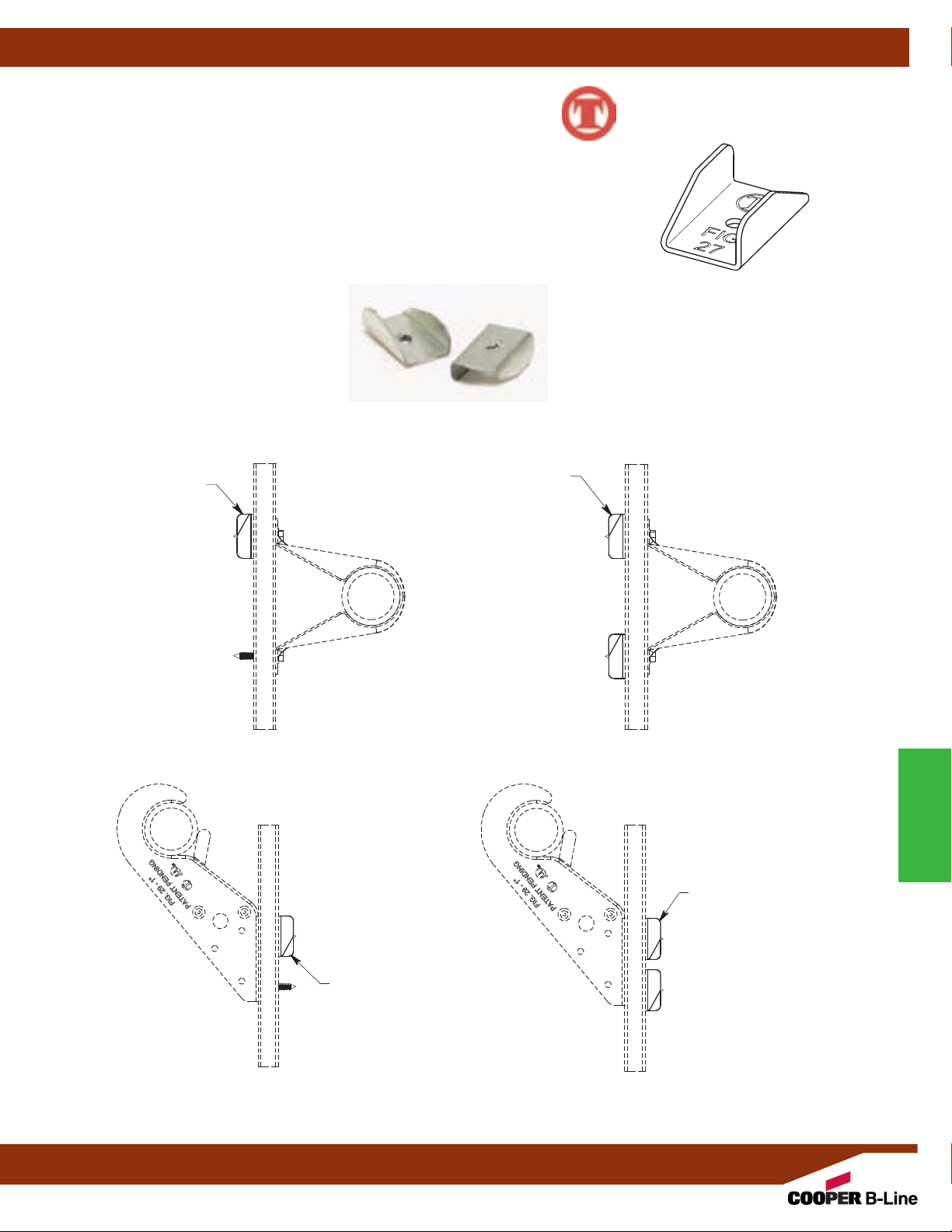
Fig. 27B - Speed Nut
Pipe Clamps
Size Range: — Fits screws supplied with all CPVC hangers.
Material: — Steel
Finish: — Pre-Galvanized (Zinc)
Function: — To be used anywhere a screw cannot achieve full embedment due to
thickness of wood structural material when installed. Fig. 27B allows full pull out load
capacity of screws when installed to the standard screws supplied with all CPVC
hangers (Fig. 22, 23, 24, 28, 28M, 29, and B3184).
Fig. 27B
(1) Required High
Side of Hanger
Application
Fig. 27B
(2) Required
™
Hanger Application
Fig. 27B
(1) Required High Side
of Hanger Application
Hanger Application
All dimensions in charts and on drawings are in inches. Dimensions shown in parentheses are in millimeters unless otherwise specified.
Hanger and Restraint
Application
Fig. 27B
(2) Required
Hanger and Restraint
Application
97
Pipe Clamps
Page 100

Pipe Clamps
Fig. 28 - “Stand-Off” Hanger & Restrainer for CPVC Plastic Pipe
Size Range: — 3/4"
(20mm)
through 2"
(50mm)
Material: — Steel, Pre-Galvanized
Function: — Designed to be used as a hanger and restrainer for CPVC piping where
the "stand-of
f" design will ease installation by eliminating the need for wood blocking.
Features:
• Flared edge design protects CPVC pipe from any rough or abrasive surfaces.
• Unique twist and lock design holds pipe firmly in place and allows retrofit type of installation.
• The "Stand-Off" design eliminates the need for wood block extension.
• Can be installed on horizontal or vertical piping regardless of mounting surface orientation.
• Attaches easily to wood structure with two hex head self-threading screws furnished with
product.
• Installs easily using rechargeable electrical driver with
5
/16"
(7.9mm)
extension socket
eliminating impact tool damage to pipe.
• Attaches easily to steel, minimum 18 gauge
(1.024mm)
with (2) 1/4
" x 1" tek type self drilling
tapping screws.
• UL Listed as a hanger and a restrainer for fire sprinkler piping.
Approvals: — Underwriters Laboratory Listed in the USA (UL) and Canada (cUL) to
support automatic fire sprinkler systems. May be installed into wood using fasteners
supplied with product, or into minimum 18 gauge steel using (2)
1
/4" x 1" tek type
screws. Meets and exceeds the requirements of NFPA 13, 13R and 13D. Fig. 28 satisfies
the UL vertical restraint requirement where needed. UL Listed as a hanger and vertical
restraint when installed on
3
/8"
(9.5mm)
composite wood material. Use two Fig. 27B Speed
Nuts when used as a hanger and restraint. Use one Fig. 27B Speed Nut on the upper
installed screw when used as a hanger only.
Order by: — Figure number and pipe size.
Pat. # 7,455,268, Pat. # 7,832,248
™
A
C
B
Pipe Clamps
Fig. 27B
(1) Required
High Side of
Hanger
Application
Fig. 27B
(2) Required
Hanger Application
Hanger and Restraint
Application
Pipe Size A B C Approx. Wt./100
Part No.
28-3/4
in. (mm) in. (mm) in. (mm) in. (mm) lbs. (kg)
3
/4" (20) 31/32" (77.0) 2" (50.8) 31/2" (88.9) 18 (8.1)
28-1 1" (25) 35/16" (84.1) 23/16" (55.6) 31/2" (88.9) 21 (9.5)
28-11/4 11/4" (32) 35/8" (92.1) 23/8" (60.3) 31/2" (88.9) 23 (10.4)
28-11/2 11/2" (40) 4" (101.6) 21/2" (63.5) 31/2" (88.9) 31 (14.0)
28-2 2" (50) 41/2" (114.3) 211/16" (68.3) 35/8" (92.1) 34 (15.4)
All dimensions in charts and on drawings are in inches. Dimensions shown in parentheses are in millimeters unless otherwise specified.
98
 Loading...