

Page 1

Disconnect Enclosures
Wall-Mount Enclosures
Type 4 & 4X Premier™Series with 2-Point or 3-Point Locking
Data Sheet
Application
• Provides housing for electrical controls and instruments
• Suitable for indoor or outdoor use
• Protects against circulating and windblown dust, falling
dirt, dripping non-corrosive liquids, rain, splashing
water, and hose-directed water
• Designed to house the following:
1. Allen-Bradley
with flange-mounted variable depth operating
mechanisms and Bulletin 1494V flange-mounted
variable depth operating mechanisms for circuit
breakers.
2. Cutler-Hammer
variable depth operating mechanisms with
disconnect switches and Type C371 flange-mounted
variable depth operating mechanisms for circuit
circuit breakers. Also Flex Shaft™ handle
mechanisms for circuit breakers.
3. General Electric
variable depth operating mechanisms for disconnect
switches and circuit breakers. Also Spectra Flex™
cable operators for circuit breakers.
4. ITE Max-Flex™
operating handle for disconnect switches and circuit
breakers, as well as some fixed depth operators for
disconnect switches.
5. Square D
flange mounted variable depth operating mechanisms
and Class 9422 flange-mounted variable depth
operating mechanisms or cable mechanisms for
circuit breakers.
6. ABB Controls
operating mechanisms for disconnect switches
and circuit breakers.
†
Marks are the property of their respective owners.
†
Bulletin 1494V disconnect switches
†
Type C361 flange-mounted
†
Type STDA flange handles and
†
flange-mounted variable depth
†
Class 9422 disconnect switches with
†
flange-mounted variable depth
Notes: Cooper B-Line can provide special sizes, finishes and other modifications. Consult the factory for your special requirements.
Standards
• UL 508 listed, Type 4 or 4X, Type 12 and Type 13
• CSA C22.2 No.94 certified, Type 12 and Type 13
• Conforms to NEMA standard for Type 4 and Type 12/13
Finish
• Wash and phosphate undercoat
• ANSI 61 gray polyester powder finish
• Stainless enclosures are offered with a brushed finish in both
304 and 316L stainless steel.
Accessories
• Premier panels
• NEMA panel adapters
• Depth adjustment brackets
• Print pockets
• Mounting foot kits
• EIA/TIA rack mounting angles
• Swing-out panels
Construction
• Enclosure and door are fabricated from code gauge steel
(see table)
• Hardware kit (provided) contains grounding hardware,
.312-18 flanged hex nuts for panel mounting, and sealing
washers for body mounting holes
• Body flange trough design, formed around body opening, diverts
liquid contaminants away from door opening
• Reduced width flange design increases enclosure opening
• Ground stud provided in enclosure body
• .312-18 collar studs are provided for mounting optional
Premier panels
• Enclosure mounting holes in body provided for direct mounting
or optional mounting feet
• Utility bracket provides wire management and accessory mounting
• Padlocking “tool-to-open” handle with 2-point or 3-point door
closing hardware installed
• Door is secured to the body with a unique spring-loaded
concealed hinge
• Door is easily removed and interchangeable
• Door has a seamless foam-in-place gasket
• Door opens 170° for easy access
• Latching system interlocks with the disconnect handle for added
safety
Discount Schedule: C2
Subclass: TC0 & TE0
Important Note
Door closing hardware, handle,latching bar, latching bar bracket
interlock, hardware and instruction sheet to locate and install
disconnects are furnished with enclosure.
Disconnect switch (or circuit breaker), operating handle and
operating mechanism are not
disconnect ordering information pages 301 - 306
Disconnect Encl.
furnished with enclosure, see
Electrical Enclosures
299
Page 2
Disconnect Enclosures
Wall-Mount Enclosures
Type 4 & 4X Premier™Series with 2-Point or 3-Point Locking
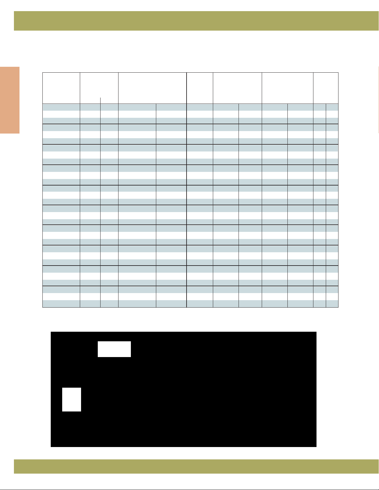
Illustration Sheet and Catalog Number
Enclosure Enclosure Size Panel Panel Size Mounting
Door Body Height x Width x Depth
Disconnect Encl.
Gauge Gauge
A x B x C
Catalog Number in. in. in. mm Number in. mm in. mm in. mm
DSC20228 2020P
DSC20228SS4 14 16 20.00 x 22.00 x 8.00 508 x 559 x 203 2020PSS4 18.00 x 18.00 457 x 457 18.50 x 20.37 470 x 518 5.0 127
DSC20228SS6 --
DSC24228 2420P
DSC24228SS4 14 16 24.00 x 22.00 x 8.00 610 x 559 x 203 2420PSS4 22.00 x 18.00 559 x 457 22.50 x 20.37 572 x 518 6.0 153
DSC24228SS6 --
DSC24268 2424P
DSC24268SS4 14 16 24.00 x 26.00 x 8.00 610 x 660 x 203 2424PSS4 22.00 x 22.00 559 x 559 22.50 x 24.37 572 x 619 6.0 153
DSC24268SS6 --
DSC30268 3024P
DSC30268SS4 14 16 30.00 x 26.00 x 8.00 762 x 660 x 203 3024PSS4 28.00 x 22.00 711 x 559 28.50 x 24.37 724 x 619 6.0 153
DSC30268SS6 --
DSC36268 3624P
DSC36268SS4 14 14 32.00 x 26.00 x 8.00 914 x 660 x 203 3624PSS4 34.00 x 22.00 864 x 559 34.50 x 24.37 876 x 619 6.0 153
DSC36268SS6 --
DSC36328 3630P
DSC36328SS4 14 14 36.00 x 32.00 x 8.00 914 x 813 x 203 3630PSS4 34.00 x 28.00 864 x 711 34.50 x 30.37 869 x 771 6.0 153
DSC36328SS6 --
DSC423212 4230P
DSC423212SS4 14 14 42.00 x 32.00 x 12.00 1067 x 813 x 305 4230PSS4 40.00 x 28.00 1016 x 711 40.50 x 30.37 1029 x 771 21.0 53
DSC423212SS6 --
DSC423812 4236P
DSC423812SS4 14 14 42.00 x 38.00 x 12.00 1067 x 965 x 305 4236PSS4 40.00 x 34.00 1016 x 864 40.50 x 36.37 1029 x 924 21.0 53
DSC423812SS6 --
DSC483812 4836P
DSC483812SS4 14 14 48.00 x 38.00 x 12.00 1219 x 965 x 305 4836PSS4 46.00 x 34.00 1168 x 864 46.50 x 36.37 1181 x 924 24.0 610
DSC483812SS6 --
DSC603812 6036P
DSC603812SS4 14 14 60.00 x 38.00 x 12.00 1524 x 965 x 305 6036PSS4 58.00 x 34.00 1473 x 864 58.50 x 36.37 1486 x 924 30.0 762
DSC603812SS6 --
Catalog H x W D x E J
Painted Steel - Part Number alone. Stainless Steel 304 - Part Number with SS4. Stainless Steel 316 - Part Number with SS6.
Mounting Holes
.75
(19)
ø.50
(13)
D
.81
(13)
E
W
2.62
(67)
H
A
Body
opening
A - 1.75
(44)
B
Body opening
B - 3.62
(92)
2.75
(70)
3.37
(86)
.80
(20)
C
X
J
1.12
3.88
(98)
X
(28)
Order
Panel
Section X-X
Separately
Notes: Dimensions are in inches. Millimeters shown are for reference only. Data subject to change without notice.
300
Electrical Enclosures
Page 3
Wall-Mount Enclosures
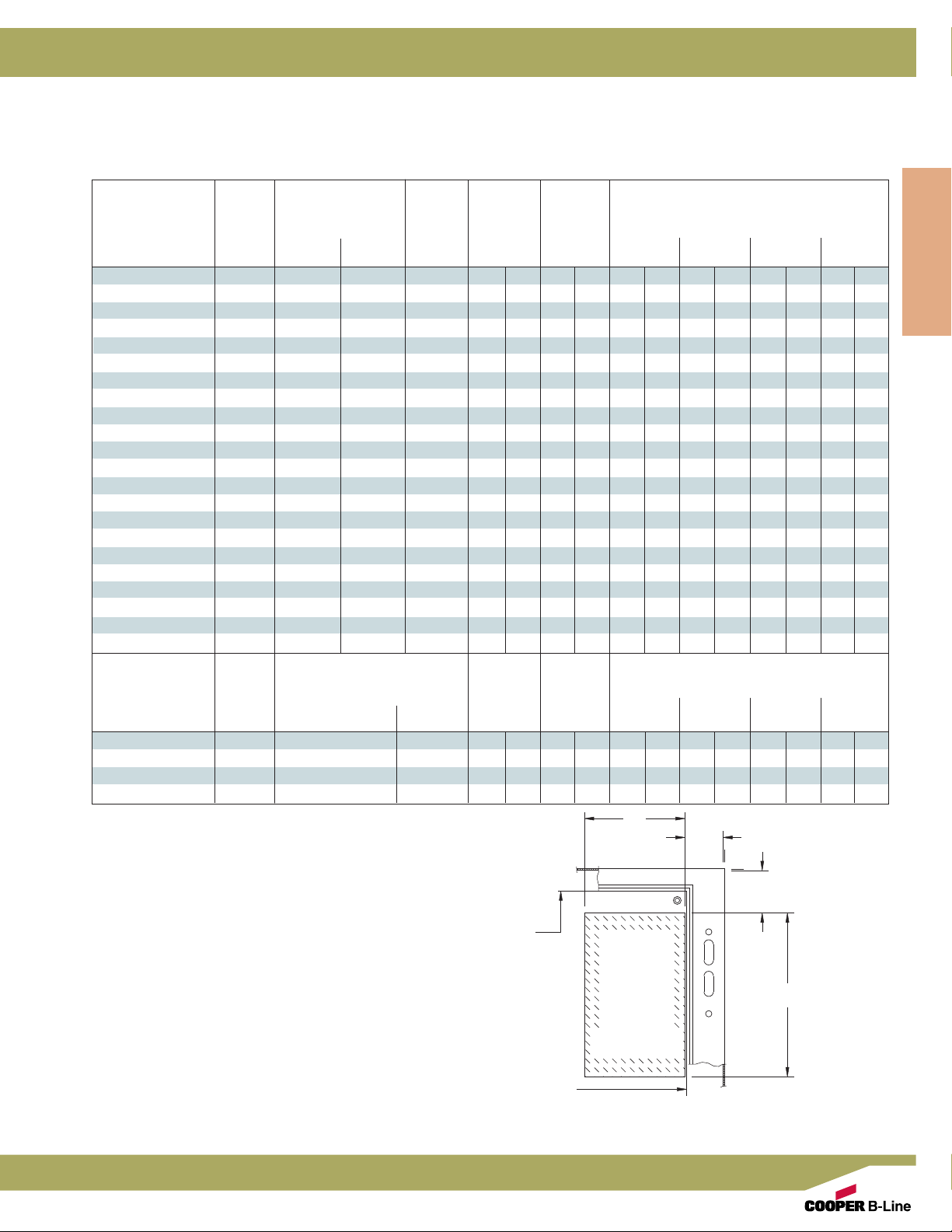
Disconnect Ordering Information
Allen-Bradley
†
1494V Disconnect Mechanism
Disconnect Enclosures
Allen-Bradley
Mechanism Amp
for Switches
DS30 30A (non) (non) -- 5.75 146 6.37 162 2.87 73 5.25 133 9.75 248 9.75 248
DS30 30A 30A 250V H,K,R 7.12 181 6.37 162 2.87 73 5.25 133 9.75 248 9.75 248
DS30 30A 30A 600V H,K,R 9.87 251 6.37 162 2.87 73 5.25 133 9.75 248 9.75 248
DS30 30A 30A 600V J 7.12 181 6.37 162 2.87 73 5.25 133 9.75 248 9.75 248
DS30 30A 60A 250V H,K 7.87 200 6.37 162 2.87 73 5.25 133 9.75 248 9.75 248
DS30 30A 60A 600V H,K 10.37 263 6.37 162 2.87 73 5.25 133 9.75 248 9.75 248
DS30 30A 60A 600V J 7.25 184 6.37 162 2.87 73 5.25 133 9.75 248 9.75 248
DS60 60A (non) (non) -- 5.87 149 6.37 162 2.75 70 5.12 130 9.62 244 9.62 244
DS60 60A 60A 250V H,K,R 8.00 203 6.37 162 2.75 70 5.12 130 9.62 244 9.62 244
DS60 60A 60A 600V H,K,R 10.50 267 6.37 162 2.75 70 5.12 130 9.62 244 9.62 244
DS60 60A 60A 600V J 7.37 187 6.37 162 2.75 70 5.12 130 9.62 244 9.62 244
DS60 60A 30A 600V H,K,R 10.00 254 6.37 162 2.75 70 5.12 130 9.62 244 9.62 244
DS60 60A 100A 250V H,K 10.50 267 6.37 162 2.75 70 5.12 130 9.62 244 9.62 244
DS60 60A 100A 600V H,K 12.50 318 6.37 162 2.75 70 5.12 130 9.62 244 9.62 244
DS60 60A 100A 600V J 9.25 235 6.37 162 2.75 70 5.12 130 9.62 244 9.62 244
DS100 100A (non) (non) -- 8.25 210 7.62 194 **3.62 92 8.12 206 8.12 206
DS100 100A 100A 250V H,K,R 13.87 352 7.62 194 **3.62 92 8.12 206 8.12 206
DS100 100A 100A 600V H,K,R 15.87 403 7.62 194 **3.62 92 8.12 206 8.12 206
DS100 100A 100A 600V J 12.62 321 7.62 194 **3.62 92 8.12 206 8.12 206
DS100 100A 200A 600V H,K 14.75 375 7.62 194 **3.62 92 8.12 206 8.12 206
DS100 100A 200A 600V H,K 17.25 438 7.62 194 **3.62 92 8.12 206 8.12 206
DS100 100A 200A 600V J 13.37 340 7.62 194 **3.62 92 8.12 206 8.12 206
Allen-Bradley
†
†
Fuse Clip Rating Fuse C
Amp Volt AB810 12 16
Class
in. mm in. mm in. mm in. mm in. mm in. mm
(when enclosure depth is:)
Circuit Breaker Type C
Mechanism for Amp (when enclosure depth is:)
Circuit Breakers
M40 150A General Electric TED, THED, TEC 6.12 155 4.25 108 4.25 108 6.62 168 11.12 282 11.12 282
M40 150A Westinghouse F (series C) 5.50 140 4.25 108 4.25 108 6.62 168 11.12 282 11.12 282
M50 250A Westinghouse J (series C) 11.00 279 4.50 114 ****10.62 270 10.62 270
M60 400A Westinghouse K (series C) 11.00 279 5.87 149 ****10.50 267 10.50 267
* Do not install disconnects in this depth enclosure.
The dimensional information provided in this table is derived from
information supplied by the manufacturer of the equipment to be
installed. Fit and function of all equipment should be checked before
and after installation to assure proper and safe operation and compliance
with the applicable regulations, codes and standards.
Manufacturer Frame(s) AB8 10 12 16
Disconnect Mounting
in. mm in. mm in. mm in. mm in. mm in. mm
B
2.87
(73)
panel
this area
represents
disconnect
switch or
Location
circuit
breaker
Disconnect Encl.
C
A
†
Marks are the property of their respective owners.
Notes: Dimensions are in inches. Millimeters shown are for reference only. Data subject to change without notice.
Electrical Enclosures
panel
301
Page 4

Disconnect Enclosures
Wall-Mount Enclosures
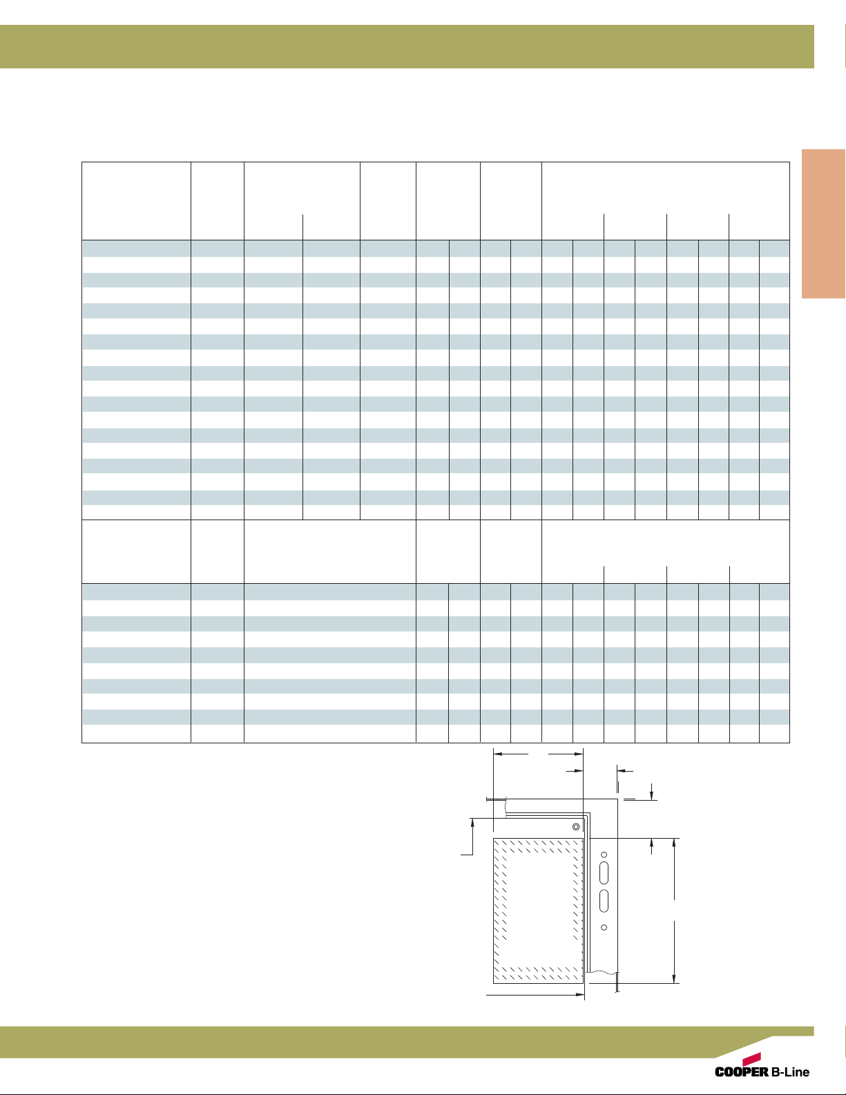
Disconnect Ordering Information
Cutler-Hammer
†
C361 Disconnect Mechanism
Cutler-Hammer
†
Fuse Clip Rating Fuse C
Mechanism Amp
Amp Volt AB810 12 16
Disconnect Encl.
for Switches
NC 30A (non) (non) -- 6.00 152 5.75 146 3.50 89 5.75 146 10.25 260 10.25 260
SC21 30A 30A 250V H,K,R 9.00 229 5.75 146 3.50 89 5.75 146 10.25 260 10.25 260
SC61 30A 30A 600V H,K,R 9.00 229 5.75 146 3.50 89 5.75 146 10.25 260 10.25 260
SC61 30A 30A 600V J 9.00 229 5.75 146 3.50 89 5.75 146 10.25 260 10.25 260
SC61 30A 60A 250V H,K,R 9.50 241 5.75 146 3.50 89 5.75 146 10.25 260 10.25 260
ND 60A (non) (non) -- 6.00 152 5.75 146 3.50 89 5.75 146 10.25 260 10.25 260
SD22 60A 30A 600V J 9.00 229 5.75 146 3.50 89 5.75 146 10.25 260 10.25 260
SD22 60A 60A 250V H,K,R 9.50 241 5.75 146 3.50 89 5.75 146 10.25 260 10.25 260
SD62 60A 60A 600V H,K,R 9.50 241 5.75 146 3.50 89 5.75 146 10.25 260 10.25 260
SD62 60A 60A 600V J 9.00 229 5.75 146 3.50 89 5.75 146 10.25 260 10.25 260
NE 100A (non) (non) -- 6.00 152 7.12 181 3.00 76 5.37 136 9.87 251 9.87 251
SE263 100A 100A 250V H,K,R 10.62 270 7.12 181 3.00 76 5.37 136 9.87 251 9.87
SE263 100A 100A 600V H,K,R 10.62 270 7.12 181 3.00 76 5.37 136 9.87 251 9.87
SE263 100A 100A 600V J 9.37 238 7.12 181 3.00 76 5.37 136 9.87 251 9.87
(2)
NF
SF264
SF264
SF264
(2)
(2)
(2)
200A (non) (non) -- 16.75 425 9.75 248 ****8.00 203 8.00
200A 200A 250V H,K,R 16.75 425 9.75 248 ****8.00 203 8.00 203
200A 200A 600V H,K,R 16.75 425 9.75 248 ****8.00 203 8.00 203
200A 200A 600V J 16.75 425 9.75 248 ****8.00 203 8.00 203
C371 Disconnect Mechanism
Cutler-Hammer
Mechanism for
Circuit Breakers
C371E
C371F
C371F
C371G
C371E
C371F
C371F
C371G
* Do not install disconnects in this depth enclosure.
(1)
Wire bending space “C” does not allow for the maximum size cable
in some depth enclosures.
(2)
Do not install 200A switch in enclosures less than 30 inches high.
The dimensional information provided in this table is derived from
information supplied by the manufacturer of the equipment to be
installed. Fit and function of all equipment should be checked before
and after installation to assure proper and safe operation and
compliance with the applicable regulations, codes and standards.
†
Marks are the property of their respective owners.
†
Circuit Breaker Type C
Amp (when enclosure depth is:)
Manufacturer Frame(s) AB 8 10 12 16
(1)
(1)
(1)
(1)
(1)
(1)
(1)
(1)
150A Cutler-Hammer HMCP,FS,FH 6.50 165 5.25 133 4.43 113 6.81 173 11.43 290 11.431290
225A Cutler-Hammer HMCP,JS,JH,JL 11.50 292 7.75 197 **6.75 171 11.25 286 11.25
400A Cutler-Hammer HMCP,KS,KH 10.50 267 7.75 197 ****10.75 273 10.75
600A Cutler-Hammer LS,LH 9.75 248 11.62 295 ****9.25 235 9.25
150A Westinghouse F (series C) 6.50 165 5.25 133 4.43 113 6.81 173 11.43 290 11.43
250A Westinghouse J (series C) 11.50 292 7.75 197 **6.75 171 11.25 286 11.25
400A Westinghouse K (series C) 10.50 267 7.75 197 ****10.75 273 10.75
600A Westinghouse LA,LC 10.87 276 11.62 295 ****9.25 235 9.25
Disconnect Mounting
Notes: Dimensions are in inches. Millimeters shown are for reference only. Data subject to change without notice.
Class
(when enclosure depth is:)
in. mm in. mm in. mm in. mm in. mm in. mm
in. mm in. mm in. mm in. mm in. mm in. mm
B
2.87
(73)
C
panel
this area
represents
disconnect
switch or
A
circuit
Location
breaker
panel
1
251
1
251
1
251
1
203
1
286
1
273
1
235
1
290
1
286
1
273
1
235
302
Electrical Enclosures
Page 5
Wall-Mount Enclosures
Disconnect Ordering Information
General Electric
†
Disconnect Enclosures
TDA Disconnect Mechanism
General Electric
Mechanism Amp
for Switches
TDOM1A 30A (non) (non) -- 6.31 160 5.00 127 6.18 157 7.62 194 12.12 308 12.12 308
TDOM1A 30A 30A 250V H,R 6.31 160 5.00 127 6.18 157 7.62 194 12.12 308 12.12 308
TDOM1B 30A 30A 600V H,R 10.93 278 5.00 127 6.18 157 7.62 194 12.12 308 12.12 308
TDOM1B 30A 30A 250V H,R 10.93 278 5.00 127 6.18 157 7.62 194 12.12 308 12.12 308
TDOM1B 30A 60A 600V H,R 10.93 278 5.00 127 6.18 157 7.62 194 12.12 308 12.12 308
TDOM1A 60A (non) (non) -- 6.31 160 5.00 127 6.18 157 7.62 194 12.12 308 12.12 308
TDOM1B 60A 60A 250V H,R 10.93 278 5.00 127 6.18 157 7.62 194 12.12 308 12.12 308
TDOM1B 60A 60A 600V H,R 10.93 278 5.00 127 6.18 157 7.62 194 12.12 308 12.12 308
TDOM1B 60A 100A 250V H,R 10.93 278 5.00 127 6.18 157 7.62 194 12.12 308 12.12 308
TDOM1B 60A 100A 600V H,R 10.93 278 5.00 127 6.18 157 7.62 194 12.12 308 12.12 308
TDOM1A 100A (non) (non) -- 6.31 160 5.00 127 6.18 157 7.62 194 12.12 308 12.12 308
TDOM1B 100A 100A 250V H,R 10.93 278 5.00 127 6.18 157 7.62 194 12.12 308 12.12 308
TDOM1B 100A 100A 600V H,R 10.93 278 5.00 127 6.18 157 7.62 194 12.12 308 12.12 308
TDOM1B 100A 200A 250V H,R 10.93 278 5.00 127 6.18 157 7.62 194 12.12 308 12.12 308
TDOM1B 100A 200A 600V H,R 10.93 278 5.00 127 6.18 157 7.62 194 12.12 308 12.12 308
TDOM2 200A (non) (non) -- 9.12 232 8.87 225 ****9.50 241 9.50 241
TDOM2 200A 200A 250V H,R 17.50 445 8.87 225 ****9.50 241 9.50 241
TDOM2 200A 200A 600V H,R 17.50 445 8.87 225 ****9.50 241 9.50 241
General Electric
Mechanism for
†
Fuse Clip Rating Fuse C
Class
Amp Volt AB810 12 16
†
Amp Circuit Breaker Type (when enclosure depth is:)
Circuit Breakers
TDOM1A 150A TEB,TEC,TED,THED 6.43 163 5.00 127 6.06 154 7.50 191 12.06 306 12.06 306
TDOM1B 150A TBI,TEC,TECL 11.06 281 5.00 127 6.06 154 7.50 191 12.06 306 12.06 306
TDOM1C 150A TEL 6.43 163 5.00 127 6.06 154 7.50 191 12.06 306 12.06 306
TDOM1D 150A THLCI 9.75 248 5.00 127 **5.12 130 9.62 244 9.62 244
TDOM3 225A TFJ,TFK,THFK,TFL 11.43 290 5.50 127 **6.06 154 10.62 270 10.62 270
TDOM4 400A TJJ,TJK4,THJK4,TJL4V 10.25 260 9.12 232 **5.12 130 9.68 246 9.68 246
TDOM4 600A TJK6,THJK6,TJ4V,TJL4V 10.25 260 9.12 232 **5.12 130 9.68 246 9.68 246
TDOM5 400A TB4,TJH6S 16.25 413 9.12 232 **5.12 130 9.68 246 9.68 246
TDOM6 225A TLB2,THLC2 14.25 362 9.12 232 ****9.12 232 9.12 232
TDOM6 400A TLB4,THLC4 15.62 397 9.12 232 ****7.75 197 7.75 197
* Do not install disconnects in this depth enclosure.
The dimensional information provided in this table is derived from
information supplied by the manufacturer of the equipment to be
installed. Fit and function of all equipment should be checked
before and after installation to assure proper and safe operation and
compliance with the applicable regulations, codes and standards.
Disconnect Mounting
Location
†
Marks are the property of their respective owners.
(when enclosure depth is:)
in. mm in. mm in. mm in. mm in. mm in. mm
C
AB8 10 12 16
in. mm in. mm in. mm in. mm in. mm in. mm
B
2.87
(73)
C
panel
this area
represents
disconnect
switch or
circuit
breaker
A
Disconnect Encl.
Electrical Enclosures
panel
Notes: Dimensions are in inches. Millimeters shown are for reference only. Data subject to change without notice.
303
Page 6

Disconnect Enclosures
Wall-Mount Enclosures
Disconnect Ordering Information
I-T-E Siemens
Encl. I-T-E†Mechanism Cable
Depth for Circuit Breaker Length Frame device nominal min max device max
Disconnect Encl.
8
10
12
16
(1)
Flexible operating cable allows disconnect to be mounted within
minimum and maximum of “A” dimension when “B” is min. (2.87).
(2)
Flexible operating cable allows disconnect to be mounted within
minimum, (2.87) and maximum of “B” dimension when “A” is
nominal.
The dimensional information provided in this table is derived from
information supplied by the manufacturer of the equipment to be
installed. Fit and function of all equipment should be checked
before and after installation to assure proper and safe operation and
compliance with the applicable regulations, codes and standards.
†
Marks are the property of their respective owners.
®†
MAX-FLEX Disconnect Mechanism
panel
(1)
B max
2.87
(73)
A min
this area
represents
disconnect
switch or
circuit
breaker
panel
Amp
FHOE036 36 125A ED,HED,ED6ETI 6.37 162 10.12 257 1.25 32 21.00 533 3.00 76 14.50 368
FHOE036 36 125A CED6ETI 8.50 216 13.25 337 4.50 114 24.25 616 3.00 76 14.50 368
FHOF036 36 250A FD,HFD,FXD,FXDETI 9.50 241 10.37 263 1.00 25 21.25 540 4.50 114 13.00 330
FHOF036 36 250A CFD,CFDETI 14.12 359 15.00 381 3.12 79 21.25 540 4.50 114 13.00 330
FHOJ036 36 400A JD,HJD,JXD2,JXD6 11.00 279 10.00 254 1.12 28 20.87 530 7.50 191 14.50 368
FHOJ036 36 400A SJD,SHJD,JXD6ETI 11.00 279 10.00 254 1.12 28 20.87 530 7.50 191 14.50 368
FHOJ036 36 400A CJD,SCJD,CJD6ETI 17.87 454 16.87 428 6.75 171 26.50 673 7.50 191 14.50 368
FHOJ036 36 600A LD,LXD,HLD 11.00 279 10.00 254 1.12 28 20.87 530 7.50 191 14.50 368
FHOJ036 36 600A SLD,SHLD,LXD6ETI 11.00 279 10.00 254 1.12 28 20.87 530 7.50 191 14.50 368
FHOJ036 36 600A CLD,SCLD,CLD6ETI 17.87 454 16.87 428 6.75 171 26.50 673 7.50 191 14.50 368
FHOE036 36 125A ED,HED,ED6ETI 6.37 162 12.50 318 2.62 67 22.87 581 3.00 76 14.25 362
FHOE036 36 125A CED6ETI 8.50 216 16.62 422 5.87 149 26.12 663 3.00 76 14.25 362
FHOF036 36 250A FD,HFD,FXD,FXDETI 9.50 241 12.75 324 2.87 73 23.12 587 4.50 114 12.75 324
FHOF036 36 250A CFD,CFDETI 14.12 359 17.37 441 5.50 140 28.00 711 4.50 114 12.75 324
FHOJ036 36 400A JD,HJD,JXD2,JXD6 11.00 279 12.37 314 2.50 64 22.75 578 7.50 191 14.25 362
FHOJ036 36 400A SJD,SHJD,JXD6ETI 11.00 279 12.37 314 2.50 64 22.75 578 7.50 191 14.25 362
FHOJ036 36 400A CJD,SCJD,CJD6ETI 17.87 454 19.25 489 9.37 238 29.62 160 7.50 191 14.25 362
FHOJ036 36 600A LD,LXD,HLD 11.00 279 12.37 314 2.50 64 22.75 578 7.50 191 14.25 362
FHOJ036 36 600A SLD,SHLD,LXD6ETI 11.00 279 12.37 314 2.50 64 22.75 578 7.50 191 14.25 362
FHOJ036 36 600A CLD,SCLD,CLD6ETI 17.87 454 19.25 489 9.37 238 29.62 160 7.50 191 14.25 362
FHOE036 36 125A ED,HED,ED6ETI 6.37 162 17.00 432 6.37 162 27.50 699 3.00 76 13.75 349
FHOE036 36 125A CED6ETI 8.50 216 19.87 505 9.62 244 30.37 771 3.00 76 13.75 349
FHOF036 36 250A FD,HFD,FXD,FXDETI 9.50 241 17.25 438 6.62 168 27.37 695 4.50 114 12.25 311
FHOF036 36 250A CFD,CFDETI 14.12 359 21.87 555 11.37 289 32.12 816 4.50 114 12.25 311
FHOJ036 36 400A JD,HJD,JXD2,JXD6 11.00 279 16.87 428 6.25 159 26.87 682 7.50 191 13.75 349
FHOJ036 36 400A SJD,SHJD,JXD6ETI 11.00 279 16.87 428 6.25 159 26.87 682 7.50 191 13.75 349
FHOJ036 36 400A CJD,SCJD,CJD6ETI 17.87 454 23.75 603 13.12 333 33.87 860 7.50 191 13.75 349
FHOJ036 36 600A LD,LXD,HLD 11.00 279 16.87 428 6.25 159 26.87 682 7.50 191 13.75 349
FHOJ036 36 600A SLD,SHLD,LXD6ETI 11.00 279 16.87 428 6.25 159 26.87 682 7.50 191 13.75 349
FHOJ036 36 600A CLD,SCLD,CLD6ETI 17.87 454 23.75 603 13.12 333 33.87 860 7.50 191 13.75 349
FHOE036 36 125A ED,HED,ED6ETI 6.37 162 17.00 432 7.75 197 26.50 673 3.00 76 11.50 292
FHOE036 36 125A CED6ETI 8.50 216 19.87 505 11.12 282 29.87 759 3.00 76 11.50 292
FHOF036 36 250A FD,HFD,FXD,FXDETI 9.50 241 17.25 438 8.12 206 26.87 682 4.50 114 10.00 254
FHOF036 36 250A CFD,CFDETI 14.12 359 21.87 555 13.00 330 31.62 803 4.50 114 10.00 254
FHOJ036 36 400A JD,HJD,JXD2,JXD6 11.00 279 16.87 428 7.62 194 26.37 670 7.50 191 11.50 292
FHOJ036 36 400A SJD,SHJD,JXD6ETI 11.00 279 16.87 428 7.62 194 26.37 670 7.50 191 11.50 292
FHOJ036 36 400A CJD,SCJD,CJD6ETI 17.87 454 23.75 603 14.62 371 33.37 848 7.50 191 11.50 292
FHOJ036 36 600A LD,LXD,HLD 11.00 279 16.87 428 7.62 194 26.37 670 7.50 191 11.50 292
FHOJ036 36 600A SLD,SHLD,LXD6ETI 11.00 279 16.87 428 7.62 194 26.37 670 7.50 191 11.50 292
FHOJ036 36 600A CLD,SCLD,CLD6ETI 17.87 454 23.75 603 14.62 371 33.37 848 7.50 191 11.50 292
Circuit Breaker A
in. mm in. mm in. mm in. mm in. mm in. mm
Disconnect Mounting
Location
Notes: Dimensions are in inches. Millimeters shown are for reference only.
Data subject to change without notice.
(2)
B
A max
304
Electrical Enclosures
Page 7

Wall-Mount Enclosures
Disconnect Ordering Information
Square D
®†
Disconnect Enclosures
9422 Disconnect Mechanism
Square D
Mechanism Amp
for Switches
Square D
†
RC-1 30A (non) (non) -- 3.37 86 6.87 174 4.62 117 7.00 178 11.50 292 11.50 292
RC-2 30A 30A 250V H,K,R 5.12 130 6.87 174 4.62 117 7.00 178 11.50 22 11.50 292
RC-3 30A 30A 600V H,K,R 8.12 206 6.87 174 4.62 117 7.00 178 11.50 292 11.50 292
RC-3 30A 30A 600V J 5.12 130 6.87 174 4.62 117 7.00 178 11.50 292 11.50 292
RC-3 30A 60A 250V H,K,R 6.12 155 6.87 174 4.62 117 7.00 178 11.50 292 11.50 292
TC-1 30A (non) (non) -- 7.75 197 5.75 146 3.12 79 5.12 130 10.50 267 10.50 267
TC-2 30A 30A 250V H,K,R 7.75 197 5.75 146 3.12 79 5.12 130 10.50 267 10.50 267
TC-3 30A 30A 600V H,K,R 7.75 197 5.75 146 3.12 79 5.12 130 10.50 267 10.50 267
TC-3 30A 30A 600V J 7.75 197 5.75 146 3.12 79 5.12 130 10.50 267 10.50 267
TC-3 30A 60A 250V H,K,R 7.75 197 5.75 146 3.12 79 5.12 130 10.50 267 10.50 267
TD-1 60A (non) (non) -- 9.50 241 6.37 162 3.62 92 6.00 152 10.50 267 10.50 267
TD-2 60A 30A 600V H,K,R 9.50 241 6.37 162 3.62 92 6.00 152 10.50 267 10.50 267
TD-2 60A 60A 250V H,K,R 7.62 194 6.37 162 3.62 92 6.00 152 10.50 267 10.50 267
TD-3 60A 60A 600V H,K,R 10.12 257 6.37 162 3.62 92 6.00 152 10.50 267 10.50 267
TD-3 60A 60A 600V J 7.62 194 6.37 162 3.62 92 6.00 152 10.50 267 10.50 267
TE-1 100A (non) (non) -- 6.12 155 8.12 206 **5.75 146 10.25 260 10.25 260
TE-2 100A 100A 250V H,K,R 8.87 225 8.12 206 **5.75 146 10.25 260 10.25 260
TE-2 100A 100A 600V H,K,R 10.87 276 8.12 206 **5.75 146 10.25 260 10.25 260
TE-2 100A 100A 600V J 7.62 194 8.12 206 **5.75 146 10.25 260 10.25 260
TE-3 100A 200A 600V J 15.12 384 8.12 206 **5.75 146 10.25 260 10.25 260
TF-1 200A (non) (non) -- 8.25 210 11.37 289 ****8.87 225 8.87 225
TF-2 200A 200A 250V H,K,R 14.25 362 11.37 289 ****8.87 225 8.87 225
TF-2 200A 200A 600V H,K,R 16.75 425 11.37 289 ****8.87 225 8.87 225
TF-2 200A 200A 600V J 12.87 327 11.37 289 ****8.87 225 8.87 225
TF-3 200A 400A 600V J 17.25 438 11.37 289 ****8.87 225 8.87 225
†
Fuse Clip Rating Fuse C
Amp Volt AB810 12 16
Class
in. mm in. mm in. mm in. mm in. mm in. mm
(when enclosure depth is:)
Circuit Breaker Type C
Mechanism for Amp (when enclosure depth is:)
Circuit Breakers
RN-1 100A FAL,FHL,FCL 6.12 155 4.25 108 3.75 95 6.12 155 10.62 270 10.62 270
RP-1 250A KAL,KHL,KCL 7.37 187 4.25 108 **6.87 174 11.37 289 11.37 289
RR-1 400A LAL,LHL,Q4L 12.25 311 4.50 114 ****7.00 178 7.00 178
RR-2 400A ILL 11.12 282 5.87 149 ****11.37 289 11.37 289
* Do not install disconnects in this depth enclosure.
The dimensional information provided in this table is derived from
information supplied by the manufacturer of the equipment to be
installed. Fit and function of all equipment should be checked
before and after installation to assure proper and safe operation
and compliance with the applicable regulations, codes and
standards.
†
Marks are the property of their respective owners.
AB8 10 12 16
in. mm in. mm in. mm in. mm in. mm in. mm
B
2.87
(73)
panel
Disconnect Mounting
Location
this area
represents
disconnect
switch or
circuit
breaker
Disconnect Encl.
C
A
Electrical Enclosures
panel
Notes: Dimensions are in inches. Millimeters shown are for reference only. Data subject to change without notice.
305
Page 8

Disconnect Enclosures
Wall-Mount Enclosures
Disconnect Ordering Information
ALLEN-BRADLEY
†
Standard enclosure designed to accept variable depth
type 1494V.
Allen-Bradley†1494V disconnect switch:
1. Disconnect switch and operating mechanism 1494V.
2. Operating handle 1494V-H1.
Disconnect Encl.
3. Trailer fuse block kit, (if required).
4. Fuse clip kit, (if required).
5. Line and load connectors, (if necessary).
6. Door hardware: 2-pt latching mechanism 1494V-L1
or 3-pt latching mechanism 1494-L2.
Allen-Bradley
1. Circuit breaker (General Electric, Westinghouse).
2. Operating mechanism.
3. Operating handle 1494V-H11.
4. Door hardware: 2-pt latching mechanism 1494V-L1
CUTLER-HAMMER
†
1494V circuit breaker:
or 3-pt latching mechanism 1494V-L2.
†
Standard enclosures designed to accept variable depth
types C361 and C371.
Cutler-Hammer†C361 disconnect switch:
1. Disconnect switch and operating mechanism.
2. Operating handle.
3. Door hardware: 2-pt latching mechanism (C361KJ4 or
C361KJ6) or 3-pt latching mechanism (C361KJ4 or
C361KJ6) and C361KR.
Cutler-Hammer†C371 circuit breaker:
1. Circuit breaker (Cutler-Hammer, Westinghouse)
2. Operating mechanism.
3. Operating handle.
4. Door hardware: 2-pt latching mechanism (C361KJ4 or
C361KJ6) or 3-pt latching mechanism (C361KJ4 or
C361KJ6) and C361KR.
General Electric†TDA circuit breaker:
1. Circuit breaker.
2. Variable depth operating mechanism.
3. Operating handle TDA1.
4. Door hardware: 2-pt latching mechanism TDV1 or 3-pt
latching mechanism TDV1 and TDV3.
I-T-E SIEMENS
†
Standard enclosures designed to accept MAX-FLEX
type FHO.
I-T-E Siemens†MAX-FLEX†circuit breaker:
1. Circuit Breaker.
2. Operating mechanism.
3. Operating handle FHOH.
4. Line and load connectors, (if necessary).
5. Operating cable (standard 36 inch).
6. Door hardware: 2-pt latching mechanism DKR2 or
3-pt latching mechanism DKR3.
SQUARE D
†
Standard enclosures designed to accept variable depth
type 9422.
Square D†9422 disconnect switch:
1. Disconnect switch and operating mechanism 9422.
2. Operating handle 9422-A1.
3. Door hardware: 2-pt latching mechanism 9423-M4 or
3-pt latching mechanism (9423-M4 or 9423-M9) and
9423-M3.
Square D†9422 circuit breaker:
1. Circuit breaker.
2. Operating mechanism.
3. Operating handle 9422-A1.
4. Door hardware: 2-pt latching mechanism 9423-M4 or
3-pt latching mechanism (9423-M4 or 9423-M9) and
9423-M3.
GENERAL ELECTRIC
†
Standard enclosures designed to accept variable
depth type TDA.
General Electric†TDA disconnect switch:
1. Disconnect switch (QMR, QMW) and variable depth
operating mechanism.
2. Operating handle TDA1.
3. Fuse clip kit or no fuse kit, (if required).
4. Door hardware: 2-pt latching mechanism TDV1 or 3-pt
latching mechanism TDV1 and TDV3.
†
Marks are the property of their respective owners.
When ordering flange-mounted disconnect equipment be sure
to include all the necessary components.
1. Latching bar, latching bar bracket interlock and hardware
are furnished with the enclosure.
2. Disconnects and related components are available from the
manufacturer, see pages 301 - 306.
Notes: Data subject to change without notice.
306
Important Note
Electrical Enclosures
 Loading...