

Page 1

Cable & Wire Management
Lay-In Wireway
Type 1 Screw Cover - Painted & Galvanized
Data Sheet
Cable & Wire Management
Application
• Houses runs of control and power cable
• Used for cable and wire junction, distribution and
termination
Standards
• UL 870 listed, Type 1
• CSA C22.2 No. 26 certified, Type 1
• Conforms to NEMA standard for Type 1
Finish
• Wash and phosphate undercoat or galvanized
steel
• ANSI 61 gray acrylic electrocoat finish
Accessories
• Sealing devices
• Touch-up paint
• See Accessories section
Construction
• Wireway body and cover are fabricated from code gauge steel
or galvanized steel, (see table, pages 9 & 10)
• Wireway body has mounting holes on the back
• Wireway is available with or without knockouts
• Wireway fittings have no knockouts, ends are available with or
without knockouts
• Cover is secured to the body with plated screws
• Keyhole slots are furnished on the wireway cover which allow
easy access to the inside without removing the screws
• Wireway exceeding 72 inches in length has two overlapping
covers
• Variety of fittings allow runs which can change direction,
junction and terminate
• Standard wireway connectors (sold separately) have a
gate feature which can swing completely open allowing for
lay-in of wire and cable
• Interchangeable with Type 1 Hinge Cover Wireway and
Fittings when HSCA connector is used, (see page 17)
Discount Schedule: A2
Subclass: AK1 & Z40
Notes: Cooper B-Line can provide special sizes, finishes and other modifications. Consult the factory for your special requirements.
8
Electrical Enclosures
Page 2
Cable & Wire Management
Lay-In Wireway
Type 1 Screw Cover - Painted & Galvanized
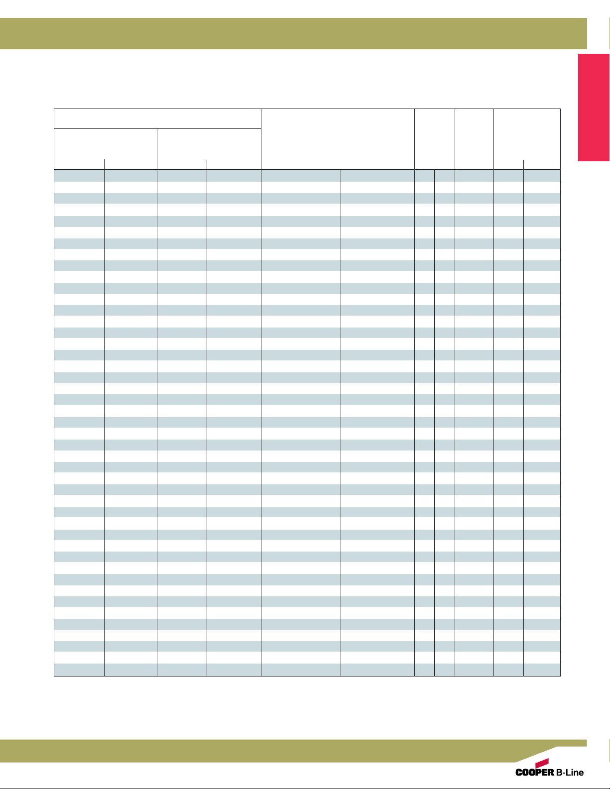
Catalog Number
Wireway Catalog Number Wireway Size Knockout
Quantity
Painted Galvanized Height x Depth x Length
A x B x C
KO No KO KO No KO
2212 G 2212 G NK -- 2212 GGV NK 2.50 x 2.50 x 12.00 64 x 64 x 305 1.25 32 16 33
2224 G 2224 G NK 2224 GGV 2224 GGV NK 2.50 x 2.50 x 24.00 64 x 64 x 610 1.25 32 16 77
2236 G 2236 G NK 2236 GGV 2236 GGV NK 2.50 x 2.50 x 36.00 64 x 64 x 914 1.25 32 16 11 11
2248 G 2248 G NK -- 2248 GGV NK 2.50 x 2.50 x 48.00 64 x 64 x 1219 1.25 32 16 15 15
2260 G 2260 G NK 2260 GGV 2260 GGV NK 2.50 x 2.50 x 60.00 64 x 64 x 1524 1.25 32 16 23 23
22120 G 22120 G NK 22120 GGV 22120 GGV NK 2.50 x 2.50 x 120.00 64 x 64 x 3048 1.25 32 16 39 39
-- 3312 G NK -- -- 3.00 x 3.00 x 12.00 76 x 76 x 305 1.50 38 16 33
-- 3324 G NK -- -- 3.00 x 3.00 x 24.00 76 x 76 x 610 1.50 38 16 77
-- 3336 G NK -- -- 3.00 x 3.00 x 36.00 76 x 76 x 914 1.50 38 16 11 11
-- 3348 G NK -- -- 3.00 x 3.00 x 48.00 76 x 76 x 1219 1.50 38 16 15 15
-- 3360 G NK -- -- 3.00 x 3.00 x 60.00 76 x 76 x 1524 1.50 38 16 19 19
-- 3372 G NK -- -- 3.00 x 3.00 x 72.00 76 x 76 x 1829 1.50 38 16 23 23
-- 33120 G NK -- -- 3.00 x 3.00 x 120.00 76 x 76 x 3048 1.50 38 16 39 39
4412 G 4412 G NK 4412 GGV 4412 GGV NK 4.00 x 4.00 x 12.00 102 x 102 x 305 2.75 70 16 33
4418 G 4418 G NK -- 4418 GGV NK 4.00 x 4.00 x 18.00 102 x 102 x 457 2.75 70 16 55
4424 G 4424 G NK 4424 GGV 4424 GGV NK 4.00 x 4.00 x 24.00 102 x 102 x 610 2.75 70 16 77
4436 G 4436 G NK 4436 GGV 4436 GGV NK 4.00 x 4.00 x 36.00 102 x 102 x 914 2.75 70 16 11 11
4448 G 4448 G NK 4448 GGV 4448 GGV NK 4.00 x 4.00 x 48.00 102 x 102 x 1219 2.75 70 16 15 15
4460 G 4460 G NK 4460 GGV 4460 GGV NK 4.00 x 4.00 x 60.00 102 x 102 x 1524 2.75 70 16 19 19
4472 G 4472 G NK 4472 GGV 4472 GGV NK 4.00 x 4.00 x 72.00 102 x 102 x 1829 2.75 70 16 23 23
44120 G 44120 G NK 44120 GGV 44120 GGV NK 4.00 x 4.00 x 120.00 102 x 102 x 3048 2.75 70 16 39 39
-- 6412 G NK -- -- 6.00 x 4.00 x 12.00 152 x 102 x 305 4.25 108 16 33
-- 6418 G NK -- -- 6.00 x 4.00 x 18.00 152 x 102 x 457 4.25 108 16 55
-- 6424 G NK -- -- 6.00 x 4.00 x 24.00 152 x 102 x 610 4.25 108 16 77
-- 6436 G NK -- -- 6.00 x 4.00 x 36.00 152 x 102 x 914 4.25 108 16 11 11
-- 6448 G NK -- -- 6.00 x 4.00 x 48.00 152 x 102 x 1219 4.25 108 16 15 15
-- 6460 G NK -- -- 6.00 x 4.00 x 60.00 152 x 102 x 1524 4.25 108 16 19 19
-- 6472 G NK -- -- 6.00 x 4.00 x 72.00 152 x 102 x 1829 4.25 108 16 23 23
-- 64120 G NK -- -- 6.00 x 4.00 x 120.00 152 x 102 x 3048 4.25 108 16 39 39
6612 G 6612 G NK 6612 GGV 6612 GGV NK 6.00 x 6.00 x 12.00 152 x 152 x 305 4.25 108 16 33
6618 G 6618 G NK -- 6618 GGV NK 6.00 x 6.00 x 18.00 152 x 152 x 457 4.25 108 16 55
6624 G 6624 G NK 6624 GGV 6624 GGV NK 6.00 x 6.00 x 24.00 152 x 152 x 610 4.25 108 16 77
6636 G 6636 G NK 6636 GGV 6636 GGV NK 6.00 x 6.00 x 36.00 152 x 152 x 914 4.25 108 16 11 11
6648 G 6648 G NK 6648 GGV 6648 GGV NK 6.00 x 6.00 x 48.00 152 x 152 x 1219 4.25 108 16 15 15
6660 G 6660 G NK 6660 GGV 6660 GGV NK 6.00 x 6.00 x 60.00 152 x 152 x 1524 4.25 108 16 19 19
6672 G 6672 G NK 6672 GGV 6672 GGV NK 6.00 x 6.00 x 72.00 152 x 152 x 1829 4.25 108 16 23 23
66120 G 66120 G NK 66120 GGV 66120 GGV NK 6.00 x 6.00 x 120.00 152 x 152 x 3048 4.25 108 16 39 39
8812 G 8812 G NK 8812 GGV 8812 GGV NK 8.00 x 8.00 x 12.00 203 x 203 x 305 6.00 152 14 33
8818 G 8818 G NK -- 8818 GGV NK 8.00 x 8.00 x 18.00 203 x 203 x 457 6.00 152 14 55
8824 G 8824 G NK 8824 GGV 8824 GGV NK 8.00 x 8.00 x 24.00 203 x 203 x 610 6.00 152 14 77
8836 G 8836 G NK 8836 GGV 8836 GGV NK 8.00 x 8.00 x 36.00 203 x 203 x 914 6.00 152 14 11 11
8848 G 8848 G NK 8848 GGV 8848 GGV NK 8.00 x 8.00 x 48.00 203 x 203 x 1219 6.00 152 14 15 15
8860 G 8860 G NK 8860 GGV 8860 GGV NK 8.00 x 8.00 x 60.00 203 x 203 x 1524 6.00 152 14 19 19
8872 G 8872 G NK 8872 GGV 8872 GGV NK 8.00 x 8.00 x 72.00 203 x 203 x 1829 6.00 152 14 23 23
88120 G 88120 G NK 88120 GGV 88120 GGV NK 8.00 x 8.00 x 120.00 203 x 203 x 3048 6.00 152 14 39 39
in. mm in. mm Gauge Top Bottom
D
Cable & Wire Management
See page 10 for 10”x10” and 12”x12” wireway.
Notes: Dimensions are in inches. Millimeters shown are for reference only. Data subject to change without notice.
Electrical Enclosures
9
Page 3
Cable & Wire Management
Lay-In Wireway
Type 1 Screw Cover - Painted & Galvanized
Illustration Sheet and Catalog Number
Wireway Catalog Number Wireway Size Knockout
Quantity
Cable & Wire Management
Painted Galvanized Height x Depth x Length
A x B x C
KO No KO KO No KO
101012 G 101012 G NK -- 101012 GGV NK 10.00 x 10.00 x 12.00 254 x 254 x 305 8.00 203 14 33
101024 G 101024 G NK -- 101024 GGV NK 10.00 x 10.00 x 24.00 254 x 254 x 610 8.00 203 14 77
101036 G 101036 G NK -- 101036 GGV NK 10.00 x 10.00 x 36.00 254 x 254 x 914 8.00 203 14 11 11
101048 G 101048 G NK -- 101048 GGV NK 10.00 x 10.00 x 48.00 254 x 254 x 1219 8.00 203 14 15 15
101060 G 101060 G NK -- 101060 GGV NK 10.00 x 10.00 x 60.00 254 x 254 x 1524 8.00 203 14 19 19
101072 G 101072 G NK -- 101072 GGV NK 10.00 x 10.00 x 72.00 254 x 254 x 1829 8.00 203 14 23 23
1010120 G 1010120 G NK -- 1010120 GGV NK 10.00 x 10.00 x 120.00 254 x 254 x 3048 8.00 203 14 39 39
121212 G 121212 G NK -- 121212 GGV NK 12.00 x 12.00 x 12.00 305 x 305 x 305 10.00 254 14 33
121224 G 121224 G NK -- 121224 GGV NK 12.00 x 12.00 x 24.00 305 x 305 x 610 10.00 254 14 77
121236 G 121236 G NK -- 121236 GGV NK 12.00 x 12.00 x 36.00 305 x 305 x 914 10.00 254 14 11 11
121248 G 121248 G NK -- 121248 GGV NK 12.00 x 12.00 x 48.00 305 x 305 x 1219 10.00 254 14 15 15
121260 G 121260 G NK -- 121260 GGV NK 12.00 x 12.00 x 60.00 305 x 305 x 1524 10.00 254 14 19 19
121272 G 121272 G NK -- 121272 GGV NK 12.00 x 12.00 x 72.00 305 x 305 x 1829 10.00 254 14 23 23
1212120 G 1212120 G NK -- 1212120 GGV NK 12.00 x 12.00 x 120.00 305 x 305 x 3048 10.00 254 14 39 39
in. mm in. mm Gauge Top Bottom
D
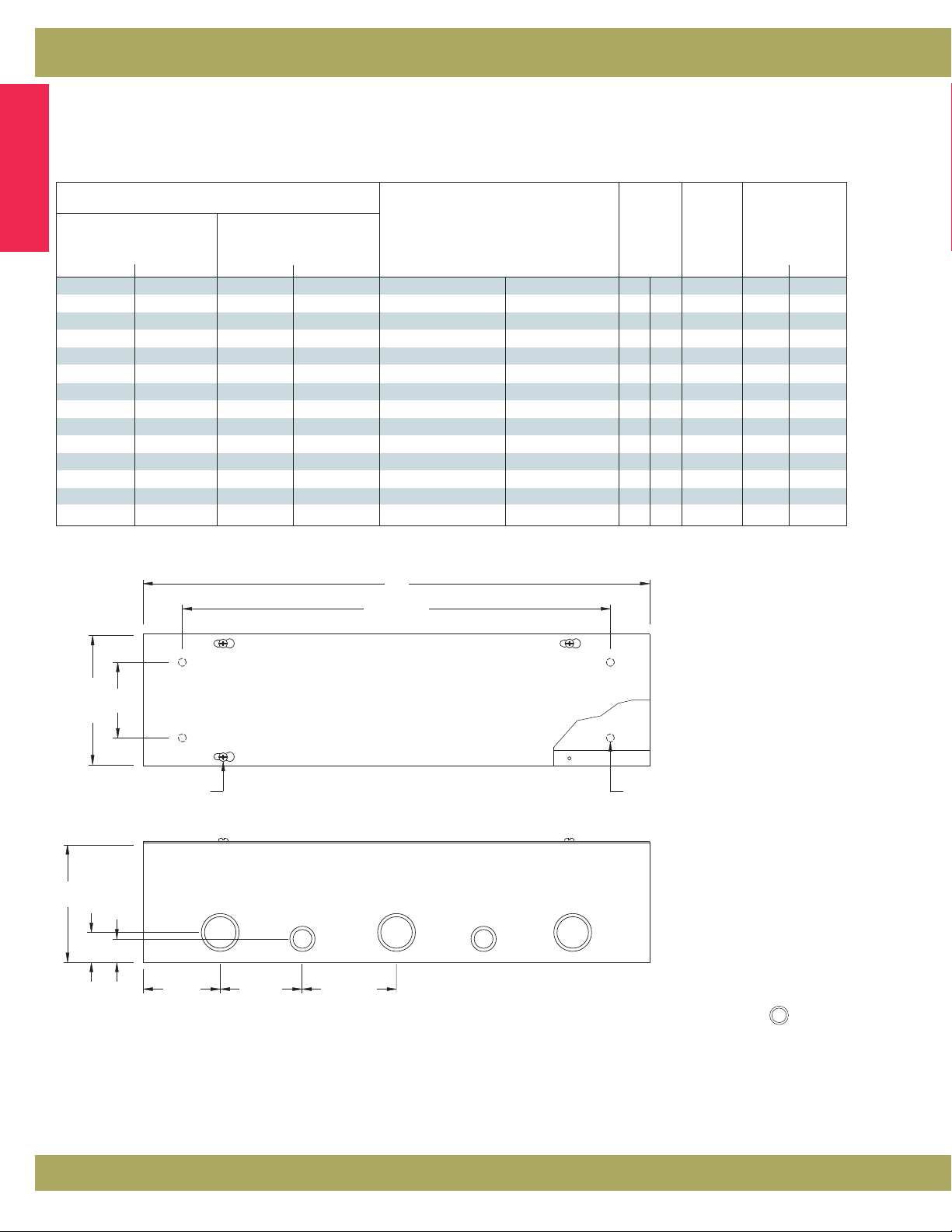
C
C-4.00
(102)
Wireway Section
Lengths from 12.00” (305 mm)
to 120.00” (3048 mm). Wireway
exceeding 72.00” (1829 mm)
has two covers. Shown with
KO’s, also available without.
A
D
cover screw
1.25
B
(32)
1.56
(40)
3.00
JJJ
3.00
(76)
(76)
typ.
spacing
Wireway Cover
H
3.00
(76)
typ.
spacing
Wireway Side
H
Note: 2.50” x 2.50” wireway has
only, 3” (76 mm) from ends and 3” (76 mm) on center. Additional
mounting holes are furnished when C dimension is over 60.00"
(1524 mm).
mounting hole
Knockout sizes:
3
H =
/4” or 1/2” conduit
1
J = 1
/4” or 1” conduit
1
/2” and 3/4” 2-way knockouts
H
Notes: Dimensions are in inches. Millimeters shown are for reference only. Data subject to change without notice.
10
Electrical Enclosures
Page 4
Cable & Wire Management
Lay-In Wireway
Type 1 Screw Cover - Painted & Galvanized
Illustration Sheet and Catalog Number
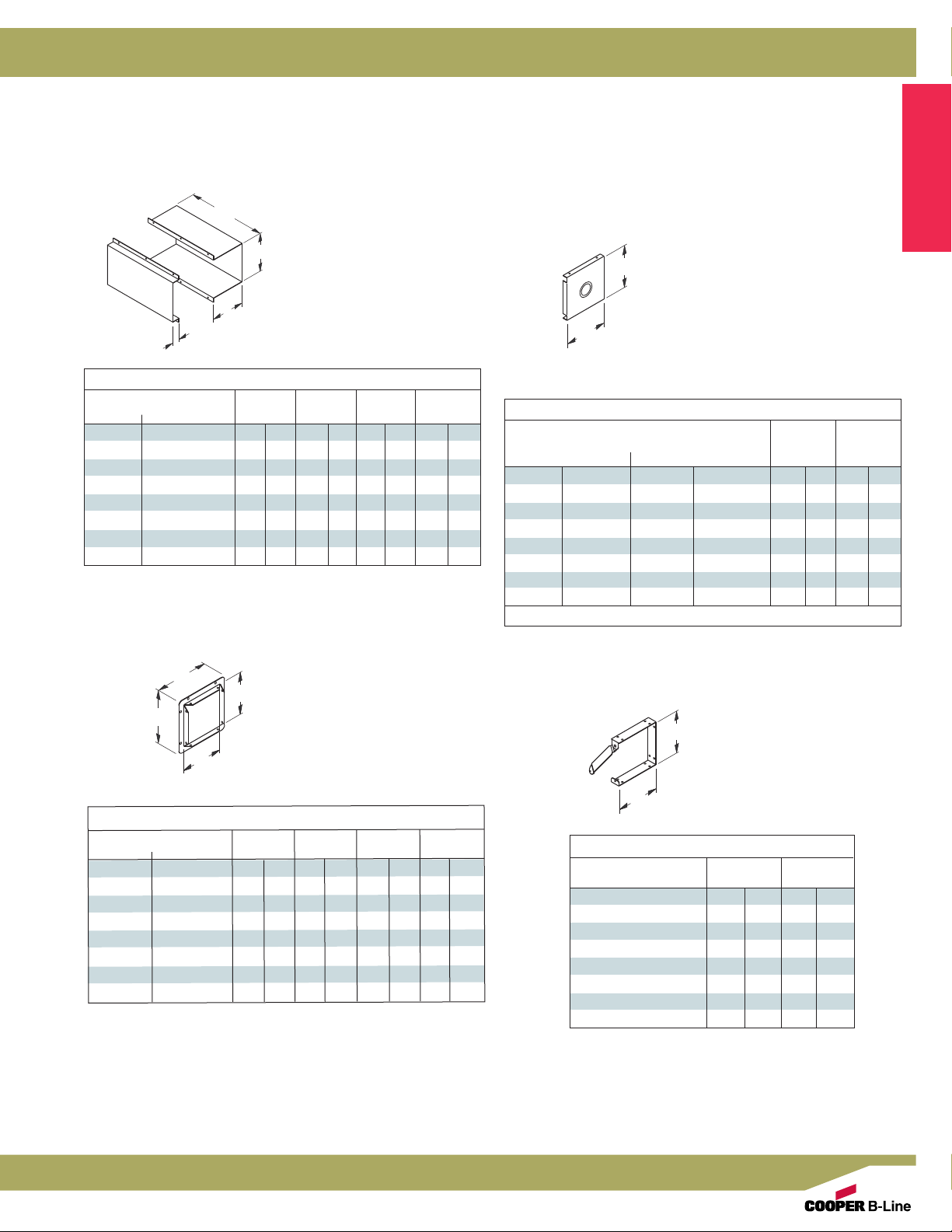
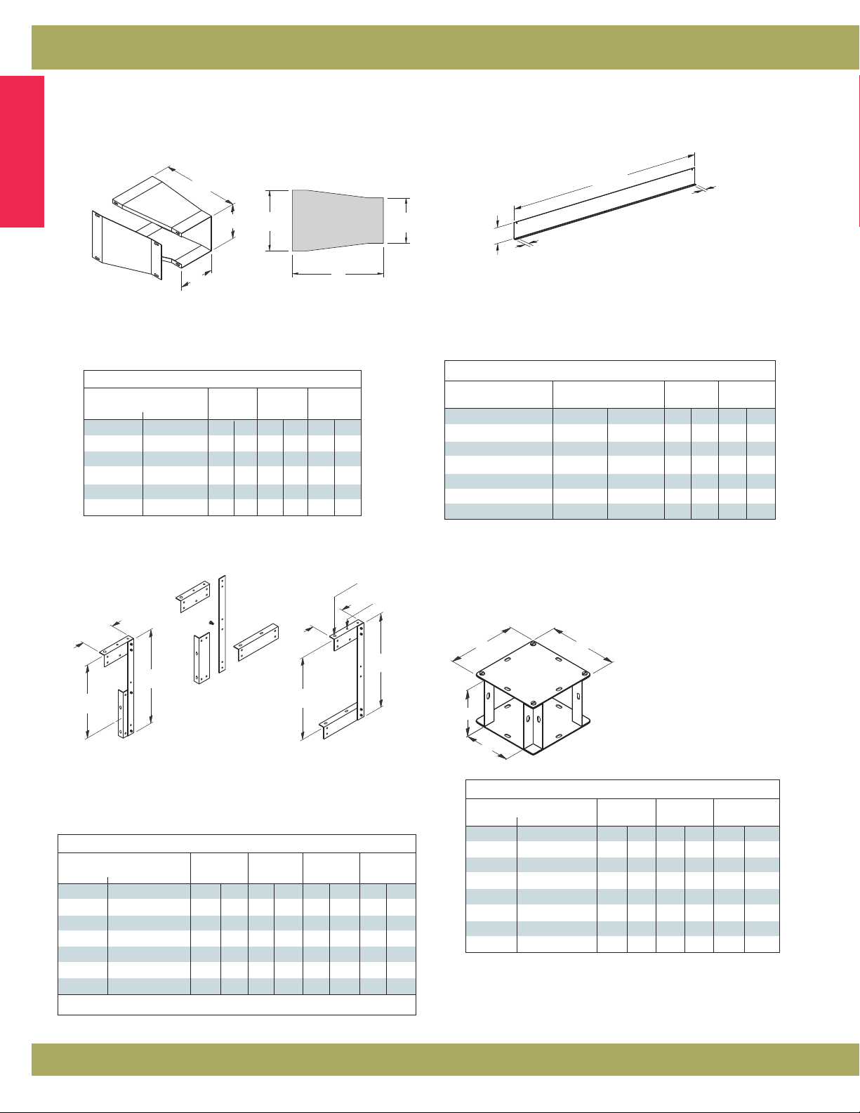
C
A
B1
B2
Telescopic Fitting
Catalog Number A B1 B2 C
Painted Galvanized in. mm in. mm in. mm in. mm
22 FTF 22 FTFGV 2.75 70 1.75 44 1.12 28 12.00 305
33 FTF
44 FTF 44 FTFGV 4.25 108 3.25 83 1.12 28 12.00 305
64 FTF
66 FTF 66 FTFGV 6.25 159 5.25 133 1.12 28 12.00 305
88 FTF 88 FTFGV 8.25 210 7.25 184 1.12 28 12.00 305
1010 FTF 1010 FTFGV 10.25 260 9.25 235 1.12 28 12.00 305
1212 FTF 1212 FTFGV 12.25 311 11.25 286 1.12 28 12.00 305
--
--
3.25 83 2.25 57 1.12 28 12.00 305
6.25 159 3.25 83 1.12 28 12.00 305
Telescopic Fitting
Adjustable length up to
10.00” (254 mm). Wraps
around the two near
joining wireway lengths to
achieve a continuous run.
End
Used to terminate wireway or fitting.
2.50” x 2.50” (64 mm x 64 mm)
through 8.00” x 8.00” (203 mm x 203
A
mm) ends have a 1.50”-1.25”
concentric 2-way KO. 10.00” x
10.00” (254 mm x 254 mm) ends
and larger have a 3.00” - 2.50”
B
concentric 2-way KO for terminating
on pipe or conduit. Also available
without KO.
End
Catalog Number AB
KO No KO KO No KO
Painted Galvanized in. mm in. mm
22 E 22 E NK 22 EGV 22 EGV NK 2.50 64 2.50 64
33 E 33 E NK -- -- 3.00 76 3.00 76
44 E 44 E NK 44 EGV 44 EGV NK 4.00 102 4.00 102
64 E 64 E NK -- -- 6.00 152 4.00 102
66 E 66 E NK 66 EGV 66 EGV NK 6.00 152 6.00 152
88 E 88 E NK 88 EGV 88 EGV NK 8.00 203 8.00 203
1010 E 1010 E NK 1010 EGV 1010 EGV NK 10.00 254 10.00 254
1212 E 1212 E NK 1212 EGV 1212 EGV NK 12.00 305 12.00 305
See drawing for KO sizes.
Cable & Wire Management
F
A
E
Wireway End Flange
Allows for a secure
connection of wireway
to an adjoining
B
enclosure or wall.
Wireway End Flange
Catalog Number
Painted Galvanized
22 GF 22 GFGV 2.50 64 2.50 64 4.00 102 4.00 102
33 GF
44 GF 44 GFGV 4.00 102 4.00 102 5.50 140 5.50 140
64 GF
66 GF 66 GFGV 6.00 152 6.00 152 7.50 191 7.50 191
88 GF 88 GFGV 8.00 203 8.00 203 9.50 241 9.50 241
1010 GF 1010 GFGV 10.00 254 10.00 254 11.50 292 11.50 292
1212 GF 1212 GFGV 12.00 305 12.00 305 13.50 343 13.50 343
--
--
A B E F
in. mm in. mm in. mm in. mm
3.00 76 3.00 76 4.50 114 4.50 114
6.00 152 4.00 102 7.50 191 5.50 140
A
Connector
Swing gate allows
for lay-in of wire
and cable.
B
Connector
Catalog Number AB
22 C 2.50 64 2.50 64
33 C 3.00 76 3.00 76
44 C 4.00 102 4.00 102
64 C 6.00 152 4.00 102
66 C 6.00 152 6.00 152
88 C 8.00 203 8.00 203
1010 C 10.00 254 10.00 254
1212 C 12.00 305 12.00 305
in. mm in. mm
Electrical Enclosures
Notes: Dimensions are in inches. Millimeters shown are for reference only. Data subject to change without notice.
11
Page 5
Cable & Wire Management
Lay-In Wireway
Type 1 Screw Cover - Painted & Galvanized
Illustration Sheet and Catalog Number
B
Cable & Wire Management
B dimensions (see catalog table), correspond to the large
end opening. Used to reduce or enlarge wireway runs.
C
A
Reducer
B
A
C
60.00
(1524)
.
875
A
H
.
875
(22)
(22)
Barrier, Bolt-On
For those installations that require separated wiring
compartments.
Reducer
Catalog Number
Painted Galvanized in. mm in. mm in. mm
2233 FR
3344 FR
4466 FR
6688 FR
881010 FR
10101212 FR
--
--
--
--
--
--
AB C
2.50 64 3.00 76 6.00 152
3.00 76 4.00 102 8.00 203
4.00 102 6.00 152 10.00 254
6.00 152 8.00 203 12.00 305
8.00 203 10.00 254 12.00 305
10.00 254 12.00 305 16.00 406
Wireway Hangers
∅ .45
∅ .25
K
K
G
G
J
(shipped
H
unassembled)*
Side Cover Assembly
For those installations where the
wireway cover must be removed
from the side.
Top Cover Assembly
For those installations where the
wireway cover must be removed
from the top.
Wireway Hanger
Catalog Number GHJK
Painted Galvanized in. mm in. mm in. mm in. mm
22 FH -- 8.50 216 6.50 165 6.50 165 2.87 73
33 FH -- 10.50 267 8.50 216 9.00 229 3.87 98
44 FH -- 12.50 318 10.50 267 10.37 263 4.87 124
66 FH -- 16.50 419 14.50 368 13.50 343 5.87 149
88 FH -- 20.50 521 18.50 470 16.75 425 6.87 174
1010 FH* -- 24.50 622 22.50 572 19.75 502 7.87 200
1212 FH* -- 28.50 724 26.50 673 22.75 578 8.87 225
*Hangers are shipped welded in the top cover assembly position.
Barrier Kit, 60” Bolt-On
Catalog Number Size Length H
in. mm in. mm in. mm
22-12BK* 2.50 x 2.50 64 x 64 60.00 1524 1.88 48
33-12BK* 3.00 x 3.00 76 x 76 60.00 1524 2.25 57
44-12BK* 4.00 x 4.00 102 x 102 60.00 1524 3.00 76
66-12BK* 6.00 x 6.00 152 x 152 60.00 1524 4.50 114
88-12BK* 8.00 x 8.00 203 x 203 60.00 1524 6.00 152
1010-12BK* 10.00 x 10.00 254 x 254 60.00 1524 8.00 203
1212-12BK* 12.00 x 12.00 305 x 305 60.00 1524 10.50 267
*Not UL or CSA listed fitting.
C
C
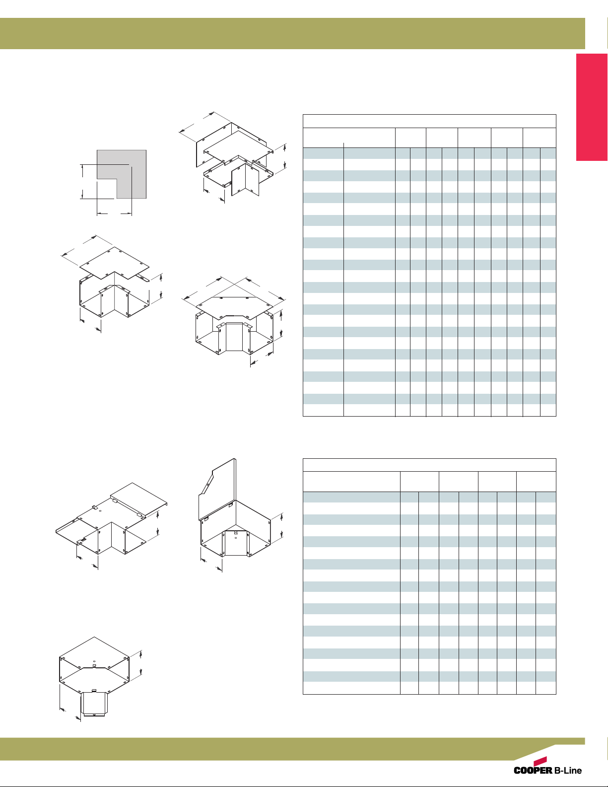
90° Elbow-Tee-Cross
Designed for left or right 90°
turns or as a tee or cross by
B
removing closure plates.
Includes two (2) closure
plates and hardware.
A
90° Elbow - Tee - Cross
Catalog Number ABC
Painted Galvanized in. mm in. mm in. mm
22 LTX 22 LTXGV 2.50 64 2.50 64 4.50 114
33 LTX -- 3.00 76 3.00 76 5.00 127
44 LTX 44 LTXGV 4.00 102 4.00 102 6.00 152
64 LTX -- 6.00 152 4.00 102 8.00 203
66 LTX 66 LTXGV 6.00 152 6.00 152 8.00 203
88 LTX 88 LTXGV 8.00 203 8.00 203 10.00 254
1010 LTX 1010 LTXGV 10.00 254 10.00 254 12.00 305
1212 LTX 1212 LTXGV 12.00 305 12.00 305 14.00 356
Notes: Dimensions are in inches. Millimeters shown are for reference only. Data subject to change without notice.
12
Electrical Enclosures
Page 6
Cable & Wire Management
Lay-In Wireway
Type 1 - Painted & Galvanized
Illustration Sheet and Catalog Number
Wireway 90˚ Elbows
Screw Cover
E
F
C
B
A
Side Opening
Side cover is removable to
allow a continuous run on
designs with 90˚ turns.
C
A
Combo Opening
Specially designed for
removing either the inside or
outside cover to allow a
continuous run with 90˚ turns.
C
Sweep Elbow
Side cover design with a
larger radius for 90°
sweeping turns.
Cable & Wire Management
90° Elbow - Screw Cover
Catalog Number AB C E F
Painted Galvanized in. mm in. mm in. mm in. mm in. mm
22 L COMBO 22 L COMBOGV
B
33 L COMBO
44 L
COMBO 44 L COMBOGV
64 L COMBO
66 L COMBO 66 L COMBOGV
88 L COMBO 88 L COMBOGV
1010 L COMBO 1010 L COMBOGV
1212 L COMBO 1212 L COMBOGV
22 L SIDE
33 L SIDE
44 L SIDE
64 L SIDE
C
A
66 L SIDE
88 L SIDE
1010 L SIDE
1212 L SIDE
B
22 L SWEEP 22 L SWEEPGV 2.50 64 2.50 64 5.63 143 4.25 108 4.25 108
33 L SWEEP
44 L SWEEP 44 L SWEEPGV 4.00 102 4.00 102 9.41 239 7.34 186 7.34 186
64 L SWEEP
66 L SWEEP 66 L SWEEPGV 6.00 152 6.00 152 11.41 290 8.34 212 8.34 212
88 L SWEEP 88 L SWEEPGV 8.00 203 8.00 203 13.41 341 9.34 237 9.34 237
1010 L SWEEP 1010 L SWEEPGV
1212 L SWEEP 1212 L SWEEPGV
--
--
--
--
--
--
--
--
--
--
--
--
2.50 64 2.50 64 5.59 142 4.28 109 4.28 109
3.00 76 3.00 76 6.09 155 4.50 114 4.50 114
4.00 102 4.00 102 7.09 180 5.00 127 5.00 127
4.00 102 6.00 152 10.09 256 5.00 127 5.00 127
6.00 152 6.00 152 10.09 256 7.00 178 7.00 178
8.00 203 8.00 203 12.09 307 8.00 203 8.00 203
10.00 254 10.00 254 14.09 358 9.00 229 9.00 229
12.00 305 12.00 305 16.09 409 10.00 254 10.00 254
2.50 64 2.50 64 5.59 142 4.28 109 4.28 109
3.00 76 3.00 76 6.09 155 4.50 114 4.50 114
4.00 102 4.00 102 7.09 180 5.00 127 5.00 127
6.00 152 4.00 102 10.09 256 7.00 178 7.00 178
6.00 152 6.00 152 10.09 256 7.00 178 7.00 178
8.00 203 8.00 203 12.09 307 8.00 203 8.00 203
10.00 254 10.00 254 14.09 358 10.00 254 9.00 229
12.00 305 12.00 305 16.09 409 10.00 254 10.00 254
3.00 76 3.00 76 8.41 214 6.84 174 6.84 174
6.00 152 4.00 102 11.41 290 8.34 212 8.34 212
10.00 254 10.00 254 15.41 391 10.34 263 10.34 263
12.00 305 12.00 305 17.41 442 11.34 288 11.34 288
Wireway 90˚ Elbows
Hinged Cover
B
A
Outside Opening
Specifically designed to have
the outside covers hinge open
to allow a continuous run with
90˚ turns.
B
Specifically designed to have
only the inside cover hinge open
to allow a continuous run with
90˚ turns.
A
Notes: Dimensions are in inches. Millimeters shown are for reference only. Data subject to change without notice.
B
A
Side Opening
Side cover is hinged to
allow a continuous run on
designs with 90˚ sweeping
turns.
Inside Opening
90° Elbow - Hinged Cover
Catalog Number AB E F
Painted in. mm in. mm in. mm in. mm
33 FL IN 3.00 76 3.00 76 5.50 140 5.50 140
44 FL IN
66 FL IN 6.00 152 6.00 152 7.00 178 7.00 178
88 FL IN 8.00 203 8.00 203 8.00 203 8.00 203
1010 FL IN 10.00 254 10.00 254 9.00 229 9.00 229
1212 FL IN 12.00 305 12.00 305 10.00 254 10.00 254
33 FL OUT 3.00 76 3.00 76 5.50 140 5.50 140
44 FL OUT
66 FL OUT 6.00 152 6.00 152 7.00 178 7.00 178
88 FL OUT 8.00 203 8.00 203 8.00 203 8.00 203
1010 FL OUT 10.00 254 10.00 254 9.00 229 9.00 229
1212 FL OUT 12.00 305 12.00 305 10.00 254 10.00 254
33 FL SIDE 3.00 76 3.00 76 5.50 140 5.50 140
44 FL SIDE
66 FL SIDE 6.00 152 6.00 152 7.00 178 7.00 178
88 FL SIDE 8.00 203 8.00 203 8.00 203 8.00 203
1010 FL SIDE 10.00 254 10.00 254 9.00 229 9.00 229
1212 FL SIDE 12.00 305 12.00 305 10.00 254 10.00 254
4.00 102 4.00 102 6.00 152 6.00 152
4.00 102 4.00 102 6.00 152 6.00 152
4.00 102 4.00 102 6.00 152 6.00 152
Electrical Enclosures
13
Page 7
Cable & Wire Management
Lay-In Wireway
Type 1 Screw Cover - Painted & Galvanized
Illustration Sheet and Catalog Number
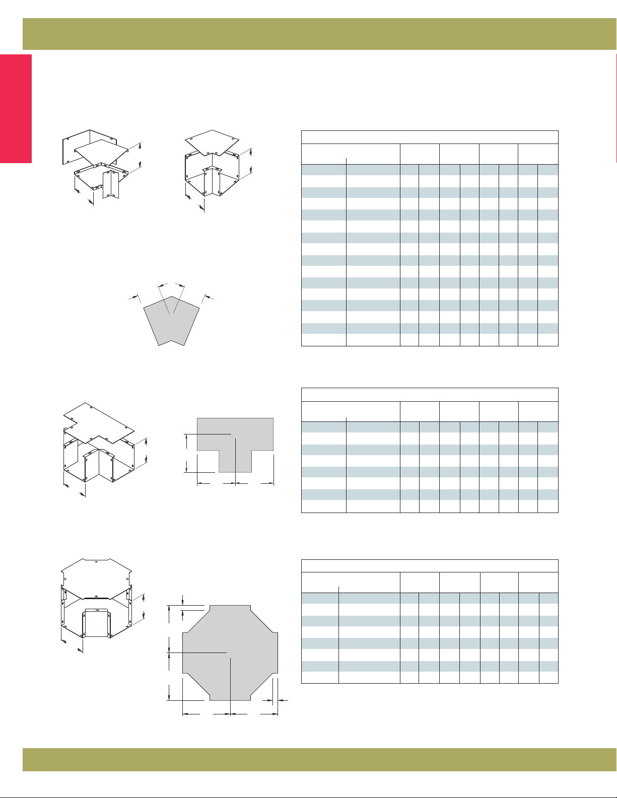
Wireway 45˚ Elbows
Cable & Wire Management
A
Combo Opening
Similar to the 90˚ elbow
design except a 45˚ turn.
Both inside and outside
covers removable.
B
A
Side Opening
Similar to the 90˚ side opening
design except for a 45˚ turn.
Excellent for combining two to
make a gradual sweeping 90˚ turn.
E
F
B
45° Elbow
Catalog Number AB E F
Painted Galvanized
2245 L COMBO 2245 L COMBOGV 2.50 64 2.50 64 1.72 44 1.72 44
3345 L COMBO --
4445 L COMBO 4445 L COMBOGV 4.00 102 4.00 102 2.75 70 2.75 70
6445 L COMBO -- 4.00 102 6.00 153 2.75 70 2.75 70
6645 L COMBO 6645 L COMBOGV 6.00 153 6.00 153 3.18 81 3.18 81
8845 L COMBO 8845 L COMBOGV 8.00 203 8.00 203 3.62 92 3.62 92
101045 L COMBO 101045 L COMBOGV
121245 L COMBO 121245 L COMBOGV
2245 L SIDE -- 2.50 64 2.50 64 1.97 50 1.97 50
3345 L SIDE --
4445 L SIDE -- 4.00 102 4.00 102 2.75 70 2.75 70
6445 L SIDE -- 6.00 153 4.00 102 3.18 81 3.18 81
6645 L SIDE -- 6.00 153 6.00 153 3.18 81 3.18 81
8845 L SIDE -- 8.00 203 8.00 203 3.62 92 3.62 92
101045 L SIDE -- 10.00 254 10.00 254 4.06 103 4.06 103
121245 L SIDE -- 12.00 305 12.00 305 4.50 114 4.50 114
in. mm in. mm in. mm in. mm
3.00 76 3.00 76 2.56 65 2.56 65
10.00 254 10.00 254 4.06 103 4.06 103
12.00 305 12.00 305 4.50 114 4.50 114
3.00 76 3.00 76 2.56 65 2.56 65
Tee
Side cover design where a “T”
junction is necessary.
B
A
E
F
F
Catalog Number ABEF
Painted Galvanized in. mm in. mm in. mm in. mm
22 T 22 TGV 2.50 64 2.50 64 4.25 108 4.25 108
33 T
44 T 44 TGV 4.00 102 4.00 102 5.00 127 5.00 127
64 T
66 T 66 TGV 6.00 153 6.00 153 7.00 178 7.00 178
88 T 88 TGV 8.00 203 8.00 203 8.00 203 8.00 203
1010 T 1010 TGV 10.00 254 10.00 254 9.00 229 9.00 229
1212 T 1212 TGV 12.00 305 12.00 305 10.00 254 10.00 254
-- 3.00 76 3.00 76 4.50 114 4.50 114
-- 6.00 153 4.00 102 7.00 178 7.00 178
Tee
Cross
Side cover and broad body design to
junction cable run in four directions.
Cross
.75
(19)
B
E
A
E
Catalog Number ABEF
Painted Galvanized in. mm in. mm in. mm in. mm
22 X 22 XGV 2.50 64 2.50 64 4.25 108 4.25 108
33 X
44 X 44 XGV 4.00 102 4.00 102 6.12 155 6.12 155
64 X
66 X 66 XGV 6.00 152 6.00 152 7.12 181 7.12 181
88 X 88 XGV 8.00 203 8.00 203 8.12 206 8.12 206
1010 X 1010 XGV 10.00 254 10.00 254 9.12 232 9.12 232
1212 X 1212 XGV 12.00 305 12.00 305 10.12 257 10.12 25
--
--
3.00 76 3.00 76 5.62 143 5.62 143
6.00 152 4.00 152 7.12 181 7.12 181
.75
F
Notes: Dimensions are in inches. Millimeters shown are for reference only. Data subject to change without notice.
F
(19)
14
Electrical Enclosures
Page 8

Cable & Wire Management
Lay-In Wireway
Type 1 Quick-Connect Hinge Cover
Data Sheet
Reversible and
removable hinge
cover
Cable & Wire Management
Pre-installed
hardware on quick
connector
Application
• Houses runs of control and power cable
• Used for cable and wire junction, distribution and
termination
Standards
• UL 870 listed, Type 1
• CSA C22.2 No. 26 certified, Type 1
• Conforms to NEMA standard for Type 1
Finish
• Wash and phosphate undercoat
• ANSI 61 gray acrylic electrocoat finish
Accessories
• Touch-up paint
• See Accessories section
Protected by U.S. Patents 7,525,044 &
7,762,042
Construction
• Wireway body and cover are fabricated from code gauge steel,
(see table, page 16)
• Wireway body has mounting holes on the back
• Wireway is available with or without knockouts
• Wireway fittings have no knockouts, ends are available with or
without knockouts
• Wireway exceeding 72 inches in length has two overlapping
covers
• Variety of fittings allow runs which can change directions,
junction and terminate
• Wireway connectors (sold separately) have a gate feature
which can swing completely open allowing for lay-in of wire
and cable
• Universal style connectors are also available for adapting to
other manufacturer’s wireway, (see page 17)
• Except for wireway ends, completely interchangeable with
Type 1 screw cover wireway and fittings through use of the
adapter style connector HSCA, (see page 17)
Discount Schedule: A2
Subclass: HS1
Electrical Enclosures
Notes: Cooper B-Line can provide special sizes, finishes and other modifications. Consult the factory for your special requirements.
15
Page 9

Cable & Wire Management
Lay-In Wireway
Type 1 Quick-Connect Hinge Cover
Illustration Sheet and Catalog Number
Wireway Wireway Size Knockout
Catalog Number Height x Depth x Length D Quantity
KO No KO in. mm in. mm Gauge Top Bottom
Cable & Wire Management
2212 HS 2212 HS NK 2.50x 2.50x 12.00 63x 63x 305 1.25 32 16 3 3
2224 HS 2224 HS NK 2.50
2236 HS 2236 HS NK 2.50
2248 HS 2248 HS NK 2.50
2260 HS 2260 HS NK 2.50
2272 HS 2272 HS NK 2.50
22120 HS 22120 HS NK 2.50
4412 HS 4412 HS NK 4.00
4424 HS 4424 HS NK 4.00x
4436 HS 4436 HS NK 4.00
4448 HS 4448 HS NK 4.00
4460 HS 4460 HS NK 4.00
4472 HS 4472 HS NK 4.00
44120 HS 44120 HS NK 4.00
6612 HS 6612 HS NK 6.00
6624 HS 6624 HS NK 6.00
6636 HS 6636 HS NK 6.00
6648 HS 6648 HS NK 6.00
6660 HS 6660 HS NK 6.00
6672 HS 6672 HS NK 6.00
66120 HS 66120 HS NK 6.00
8812 HS 8812 HS NK 8.00
8824 HS 8824 HS NK 8.00
8836 HS 8836 HS NK 8.00
8848 HS 8848 HS NK 8.00
8860 HS 8860 HS NK 8.00
8872 HS 8872 HS NK 8.00
88120 HS 88120 HS NK 8.00
101012 HS 101012 HS NK 10.00
101024 HS 101024 HS NK 10.00
101036 HS 101036 HS NK 10.00
101048 HS 101048 HS NK 10.00
101060 HS 101060 HS NK 10.00
1010120 HS 1010120 HS NK 10.00
121212 HS 121212 HS NK 12.00
121224 HS 121224 HS NK 12.00
121236 HS 121236 HS NK 12.00
121248 HS 121248 HS NK 12.00
121260 HS 121260 HS NK 12.00
1212120 HS 1212120 HS NK 12.00
A
D
cover screw
A x B x C
x
2.50x 24.00 63x 63x 610 1.25 32 16 7 7
x
2.50x 36.00 63x 63x 914 1.25 32 16 11 11
x
2.50x 48.00 63x 63x 1219 1.25 32 16 15 15
x
2.50x 60.00 63x 63x 1524 1.25 32 16 19 19
x
2.50x 72.00 63x 63x 1829 1.25 32 16 23 23
x
2.50x 120.00 63x 63x 3048 1.25 32 16 39 39
x
4.00x 12.00 102x 102x 305 2.75 70 16 3 3
x
4.00x 24.00 102x 102x 610 2.75 70 16 7 7
x
4.00x 36.00 102x 102x 914 2.75 70 16 11 11
x
4.00x 48.00 102x 102x 1219 2.75 70 16 15 15
x
4.00x 60.00 102x 102x 1524 2.75 70 16 19 19
x
4.00x 72.00 102x 102x 1829 2.75 70 16 23 23
x
4.00x 120.00 102x 102x 3048 2.75 70 16 39 39
x
6.00x 12.00 152x 152x 305 4.25 108 16 3 3
x
6.00x 24.00 152x 152x 610 4.25 108 16 7 7
x
6.00x 36.00 152x 152x 914 4.25 108 16 11 11
x
6.00x 48.00 152x 152x 1219 4.25 108 16 15 15
x
6.00x 60.00 152x 152x 1524 4.25 108 16 19 19
x
6.00x 72.00 152x 152x 1829 4.25 108 16 23 23
x
6.00x 120.00 152x 152x 3048 4.25 108 16 39 39
x
8.00x 12.00 203x 203x 305 6.00 152 14 3 3
x
8.00x 24.00 203x 203x 610 6.00 152 14 7 7
x
8.00x 36.00 203x 203x 914 6.00 152 14 11 11
x
8.00x 48.00 203x 203x 1219 6.00 152 14 15 15
x
8.00x 60.00 203x 203x 1524 6.00 152 14 19 19
x
8.00x 72.00 203x 203x 1829 6.00 152 14 23 23
x
8.00x 120.00 203x 203x 3048 6.00 152 14 39 39
x
10.00x 12.00 254x 254x 305 8.00 203 14 3 3
x
10.00x 24.00 254x 254x 610 8.00 203 14 7 7
x
10.00x 36.00 254x 254x 914 8.00 203 14 11 11
x
10.00x 48.00 254x 254x 1219 8.00 203 14 15 15
x
10.00x 60.00 254x 254x 1524 8.00 203 14 19 19
x
10.00x 120.00 254x 254x 3048 8.00 203 14 39 39
x
12.00x 12.00 305x 305x 305 10.00 254 14 3 3
x
12.00x 24.00 305x 305x 610 10.00 254 14 7 7
x
12.00x 36.00 305x 305x 914 10.00 254 14 11 11
x
12.00x 48.00 305x 305x 1219 10.00 254 14 15 15
x
12.00x 60.00 305x 305x 1524 10.00 254 14 19 19
x
12.00x 120.00 305x 305x 3048 10.00 254 14 39 39
C
C - 4.00”
Lengths from 12.00” (305 mm) to
120.00” (305 mm). Wireway
Wireway Cover
exceeding 72.00” (1829 mm) has
two covers. Shown with KO's,
also available without.
mounting hole
Wireway Section
B
1.56”
1.25”
JJJ
3.00”
3.00”
typ.
spacing
H
3.00”
typ.
spacing
H
Wireway Side
H
J
Notes: Additional mounting holes are furnished when C dimension is over 60.00" (1524 mm).
Dimensions are in inches. Millimeters shown are for reference only. Data subject to change without notice.
16
Knockout sizes:
H = 3/4” or 1/2” conduit
J = 11/4” or 1” conduit
Electrical Enclosures
Page 10

Cable & Wire Management
Lay-In Wireway
Type 1 Quick-Connect Hinge Cover
Illustration Sheet and Catalog Number
C
Telescopic Fitting
Adjustable length up to
A
10.00” (254 mm). Wraps
around the two near joining
wireway lengths to achieve
B1
B2
Telescopic Fitting
Catalog Number
22 FTF 2.75 70 1.75 44 1.12 28 12.00 305
33FTF 3.25 83 2.25 57 1.12 28 12.00 305
44 FTF 4.25 108 3.25 83 1.12 28 12.00 305
66 FTF 6.25 159 5.25 133 1.12 28 12.00 305
88 FTF 8.25 210 7.25 184 1.12 28 12.00 305
1010 FTF 10.25 260 9.25 235 1.12 28 12.00 305
1212 FTF 12.25 311 11.25 286 1.12 28 12.00 305
in. mm in. mm in. mm in. mm
a continuous run.
A B1 B2 C
Reducer
B dimensions (see catalog
table), correspond to the large
B
C
A
end opening. Used to reduce
or enlarge wireway runs.
Removable cover is secured
A
with screws.
B
C
Reducer
Catalog Number AB C
2233 FR * 2.50 63 3.00 76 6.00 152
3344 FR * 3.00 76 4.00 102 8.00 203
4466 FR * 4.00 102 6.00 152 10.00 254
6688 FR * 6.00 152 8.00 203 12.00 305
881010 FR * 8.00 203 10.00 254 12.00 305
10101212 FR * 10.00 254 12.00 305 16.00 406
* Requires use of HSCA Adapter Style Connector.
in. mm in. mm in. mm
Cable & Wire Management
A
Connector
Style
A
B
Adapter
Style
A
B
Connector
Swing gate allows for lay-in of wire
and cable.
Connector
Catalog Number AB
Connector Style Adapter Style Universal Style in. mm in. mm
22 HSC 22 HSCA 22 HSCU 2.50 63 2.50 63
44 HSC 44 HSCA 44 HSCU 4.00 102 4.00 102
66 HSC 66 HSCA 66 HSCU 6.00 152 6.00 152
88 HSC 88 HSCA 88 HSCU 8.00 203 8.00 203
1010 HSC 1010 HSCA 1010 HSCU 10.00 254 10.00 254
1212 HSC 1212 HSCA 1212 HSCU 12.00 305 12.00 305
HSC - Standard Quick Connector
HSCA - For adapting to Type 1 Screw Cover Wireway
HSCU - For adapting to competitive Wireway
Universal
Style
B
A
A
End
Used to terminate
wireway or fitting.
Shown with KO, also
B
Drawing shows screws in place.
Screws are actually packaged in
plastic bags.
available without.
End
Catalog Number ABKO
KO No KO
22 HSE 22 HSE NK 2.50 63 2.50 63 1.50 38
44 HSE 44 HSE NK 4.00 102 4.00 102 1.50 38
66 HSE 66 HSE NK 6.00 152 6.00 152 1.50 38
88 HSE 88 HSE NK 8.00 203 8.00 203 1.50 38
1010 HSE 1010 HSE NK 10.00 254 10.00 254 3.00 76
1212 HSE 1212 HSE NK 12.00 305 12.00 305 3.00 76
in. mm in. mm in. mm
Electrical Enclosures
Notes: Dimensions are in inches. Millimeters shown are for reference only. Data subject to change without notice.
17
Page 11

Cable & Wire Management
Lay-In Wireway
Type 1 Quick-Connect Hinge Cover
Illustration Sheet and Catalog Number
Wireway Hangers
Cable & Wire Management
F
Wireway End Flange
Allows for a secure connection
A
of wireway to an adjoining
E
B
enclosure or wall.
Wireway End Flange
Catalog Number ABEF
in. mm in. mm in. mm in. mm
22 HSF 2.50 63 2.50 63 4.00 102 4.00 102
44 HSF 4.00 102 4.00 102 5.50 140 5.50 140
66 HSF 6.00 152 6.00 152 7.50 191 7.50 191
88 HSF 8.00 203 8.00 203 9.50 241 9.50 241
1010 HSF 10.00 254 10.00 254 11.50 292 11.50 292
1212 HSF 12.00 305 12.00 305 13.50 343 13.50 343
60.00
(1524)
.
875
(22)
H
.
875
(22)
K
K
G
G
J
(shipped
H
unassembled)
Side Cover Assembly
For those installations where
the wireway cover must be
hinged at the side.
Top Cover Assembly
For those installations where
the wireway cover must be
hinged at the top.
Wireway Hanger
Catalog Number GH J K
in. mm in. mm in. mm in. mm
22 FH 8.50 216 8.50 216 6.50 165 2.87 73
44 FH 12.50 318 10.50 267 10.37 263 4.87 121
66 FH 16.50 419 14.50 394 13.50 340 5.87 146
88 FH 20.50 521 18.50 495 16.75 425 6.87 171
1010 FH ** 24.50 622 22.50 571 17.25 438 7.87 200
1212 FH ** 28.50 724 26.50 673 20.25 514 8.87 225
**Hangers are shipped welded in the top cover assembly position.
Barrier, Bolt-On
For those installations that require separate wiring
compartments.
Barrier Kit, 60” Bolt-On
Catalog Number Size Length H
in. mm in. mm in. mm
22-12BK* 2.50 x 2.50 64 x 64 60.00 1524 1.88 48
33-12BK* 3.00 x 3.00 76 x 76 60.00 1524 2.25 57
44-12BK* 4.00 x 4.00 102 x 102 60.00 1524 3.00 76
66-12BK* 6.00 x 6.00 152 x 152 60.00 1524 4.50 114
88-12BK* 8.00 x 8.00 203 x 203 60.00 1524 6.00 152
1010-12BK* 10.00 x 10.00 254 x 254 60.00 1524 8.00 203
1212-12BK* 12.00 x 12.00 305 x 305 60.00 1524 10.50 267
*Not UL or CSA listed fitting.
Notes: Dimensions are in inches. Millimeters shown are for reference only. Data subject to change without notice.
18
Electrical Enclosures
Page 12

Cable & Wire Management
Lay-In Wireway
Type 1 Quick-Connect Hinge Cover
Illustration Sheet and Catalog Number
Wireway 90˚ Elbows
B
A
Inside Opening
Specifically designed to have
only the inside cover hinge
open to allow a continuous
run with 90˚ turns.
A
B
B
A
Side Opening
Side cover is hinged to
allow a continuous run on
designs with 90˚ sweeping
turns.
Cable & Wire Management
90° Elbow
Catalog Number ABEF
in. mm in. mm in. mm in. mm
22 HSL IN 2.50 63 2.50 63 3.31 84 3.31 84
44 HSL IN 4.00 102 4.00 102 4.06 103 4.06 103
66 HSL IN 6.00 152 6.00 152 5.06 128 5.06 128
88 HSL IN 8.00 203 8.00 203 6.06 154 6.06 154
1010 HSL IN 10.00 254 10.00 254 7.06 179 7.06 179
1212 HSL IN 12.00 305 12.00 305 8.06 205 8.06 205
22 HSL OUT 2.50 63 2.50 63 3.38 86 3.38 86
44 HSL OUT 4.00 102 4.00 102 4.09 104 4.09 104
66 HSL OUT 6.00 152 6.00 152 5.09 129 5.09 129
88 HSL OUT 8.00 203 8.00 203 6.09 154 6.09 154
1010 HSL OUT 10.00 254 10.00 254 7.09 180 7.09 180
1212 HSL OUT 12.00 305 12.00 305 8.09 205 8.09 205
22 HSL SIDE 2.50 63 2.50 63 3.50 89 3.50 89
44 HSL SIDE 4.00 102 4.00 102 4.32 110 4.32 110
66 HSL SIDE 6.00 152 6.00 152 5.31 135 5.31 135
88 HSL SIDE 8.00 203 8.00 203 6.31 160 6.31 160
1010 HSL SIDE 10.00 254 10.00 254 7.31 185 7.31 185
1212 HSL SIDE 12.00 305 12.00 305 8.31 211 8.31 211
Outside Opening
Specifically designed to have the
outside covers hinge open to
allow a continuous run with 90˚
turns.
Wireway 45˚ Elbows
A
B
A
Combo Opening
Designed to achieve a 45˚
turn. Inside and outside
removable covers are
secured with screws.
E
F
(outside opening)
B
A
Side Opening
Designed to achieve a 45˚
turn and have the cover
removed from the side.
Excellent for combining
two to make a gradual 90˚
sweep.
.75
E
(19)
.75
(19)
F
(inside and side opening)
45° Elbow
Catalog Number ABEF
2245 HSL COMBO 2.50 63 2.50 63 1.72 43 1.72 43
4445 HSL COMBO 4.00 102 4.00 102 2.75 70 2.75 70
6645 HSL COMBO 6.00 152 6.00 152 3.18 81 3.18 81
8845 HSL COMBO 8.00 203 8.00 203 3.62 92 3.62 92
101045 HSL COMBO 10.00 254 10.00 254 4.06 103 4.06 103
121245 HSL COMBO 12.00 305 12.00 305 4.50 114 4.50 114
2245 HSL SIDE 2.50 63 2.50 63 1.72 43 1.72 43
4445 HSL SIDE 4.00 102 4.00 102 2.75 70 2.75 70
6645 HSL SIDE 6.00 152 6.00 152 3.18 81 3.18 81
8845 HSL SIDE 8.00 203 8.00 203 3.62 92 3.62 92
101045 HSL SIDE 10.00 254 10.00 254 4.06 103 4.06 103
121245 HSL SIDE 12.00 305 12.00 254 4.50 114 4.50 114
E
F
in. mm in. mm in. mm in. mm
Electrical Enclosures
Notes: Dimensions are in inches. Millimeters shown are for reference only. Data subject to change without notice.
19
Page 13

Cable & Wire Management
Lay-In Wireway
Type 1 Quick-Connect Hinge Cover
Illustration Sheet and Catalog Number
Cable & Wire Management
Tee
Side hinge cover design for
applications where a “T”
junction is necessary.
B
A
E
.75
(19)
F
F
Catalog Number ABEF
22 HST 2.50 63 2.50 63 5.38 136 4.25 198
44 HST 4.00 102 4.00 102 6.15 156 6.12 155
66 HST 6.00 152 6.00 152 7.15 181 7.12 181
88 HST 8.00 203 8.00 203 8.15 207 8.12 206
1010 HST 10.00 254 10.00 254 9.15 232 9.12 231
1212 HST 12.00 305 12.00 305 10.15 258 10.12 257
.75
(19)
Tee
in. mm in. mm in. mm in. mm
Cross
Side cover and broad body
design to junction cable
run in four directions.
Removable cover is
secured with screws.
B
A
.75
(19)
E
E
FF
Catalog Number ABEF
22 HSX 2.50 63 2.50 63 5.97 151 5.97 151
44 HSX 4.00 102 4.00 102 6.75 171 6.75 171
66 HSX 6.00 152 6.00 152 7.75 197 7.75 197
88 HSX 8.00 203 8.00 203 8.75 222 8.75 222
1010 HSX 10.00 254 10.00 254 9.75 247 9.75 247
1212 HSX 12.00 305 12.00 305 10.75 273 10.75 273
.75
(19)
Cross
in. mm in. mm in. mm in. mm
Notes: Dimensions are in inches. Millimeters shown are for reference only. Data subject to change without notice.
20
Electrical Enclosures
Page 14

Cable & Wire Management
Lay-In Wireway
Type 3R EnviroShield
Data Sheet
Cable & Wire Management
™
Install inside connector
in wireway ends and
tighten
Install and secure
hinged covers
Application
• Houses runs of power, control and communication
cable
• Used for cable and wire junction, distribution and
termination
Standards
• UL 870 listed, Type 3R
• CSA C22.2 No. 26 certified, Type 3R
• Conforms to NEMA standard for Type 3R
Material & Finish
• Galvanealed steel with ANSI 61 gray acrylic
electrocoat finish and zinc plated hardware
• Aluminum with stainless steel hardware
Accessories
• Sealing devices
• Touch-up paint
• See Accessories section
Install outside connector
around wireway splice
location
Latch shut
(padlock can be installed
if desired)
Construction
• Wireway body and cover are fabricated from code gauge steel,
or brushed aluminum (see page 22)
• Wireway body has embossed mounting holes on the back
• Cover is secured to the body with gasketed retaining screw
• Variety of fittings allow runs which can change directions, size,
junction and terminate, as well as, expansion and contraction
• Wireway connectors (sold separately) have a gate feature
which can swing completely open allowing for lay-in of wire
and cable
• Wireway connectors have a locking feature for optional
pad-locking
• Removable hinge cover construction
• Z-slots for quick-connect connection method
• Wireways 120”
(3048mm) in length have two overlapping covers
Discount Schedule: A2
Subclass: RHS
Protected by U.S. Patents 7,525,044 &
7,762,042
Notes: Cooper B-Line can provide special sizes, finishes and other modifications. Consult the factory for your special requirements.
Electrical Enclosures
21
Page 15

Cable & Wire Management
Lay-In Wireway
Type 3R EnviroShield
Illustration Sheet and Catalog Number
Wireway Section
Lengths from 12.00” to 120.00”.
Wireway exceeding 72.00” has two covers.
Cable & Wire Management
L
™
B
D
B
A
Cover Screw
Wireway Side
L
L - 4.5”
Wireway Bottom
A
Mounting Embossment
with .25” Dia. Hole (4)
Wireway Wireway Size Mounting Material
Catalog Number Height x Depth x Length Hole Spacing Thickness
Steel Aluminum
4412-3RHS NK 4412-3RAHS NK 4.00x 4.00x 12.00 101x 101x 305 2.25 57.1 16 1.52 0.080 2.03
4460-3RHS NK 4460-3RAHS NK 4.00
44120-3RHS NK 44120-3RAHS NK 4.00
6612-3RHS NK 6612-3RAHS NK 6.00
6660-3RHS NK 6660-3RAHS NK 6.00
66120-3RHS NK 66120-3RAHS NK 6.00
8812-3RHS NK 8812-3RAHS NK 8.00
8860-3RHS NK 8860-3RAHS NK 8.00
88120-3RHS NK 88120-3RAHS NK 8.00
NK = No Knockouts
x
x
x
x
x
x
x
x
A x B x C
in. mm in. mm Gauge mm In. mm
4.00x 60.00 101x 101x 1524 2.25 57.1 16 1.52 0.080 2.03
4.00x 120.00 101x 101x 3048 2.25 57.1 16 1.52 0.080 2.03
6.00x 12.00 152x 152x 305 3.75 95.2 16 1.52 0.080 2.03
6.00x 60.00 152x 152x 1524 3.75 95.2 16 1.52 0.080 2.03
6.00x 120.00 152x 152x 3048 3.75 95.2 16 1.52 0.080 2.03
8.00x 12.00 203x 203x 305 5.75 146.0 16 1.52 0.080 2.03
8.00x 60.00 203x 203x 1524 5.75 146.0 16 1.52 0.080 2.03
8.00x 120.00 203x 203x 3048 5.75 146.0 16 1.52 0.080 2.03
D Steel Aluminum
Wireway Connectors
Swing gate allows for lay-in installation of wire and cable.
Wrap-around connector provides Type 3R rating and padlocking provision.
Connector
Catalog Number AB
Steel Aluminum
44-3RHSC 44-3RAHSC 4.00 101 4.00 101
66-3RHSC 66-3RAHSC 6.00 152 6.00 152
88-3RHSC 88-3RAHSC 8.00 203 8.00 203
in. mm in. mm
3.0”
B
A
Connector Screw
Clearance Holes
Padlockable Latch
Notes: Dimensions are in inches. Millimeters shown are for reference only. Data subject to change without notice.
22
Electrical Enclosures
Page 16

Cable & Wire Management
Lay-In Wireway
Type 3R EnviroShield
Illustration Sheet and Catalog Number
Wireway End
Used to terminate wireway or fitting.
Wireway End Flange
Allows for a secure connection of wireway
or fitting to an adjoining enclosure or wall.
™
Cable & Wire Management
Wireway End
Catalog Number AB
B
A
B
A
A
B
Steel Aluminum
44-3RHSE NK 44-3RAHSE NK 4.00 101 4.00 101
66-3RHSE NK 66-3RAHSE NK 6.00 152 6.00 152
88-3RHSE NK 88-3RAHSE NK 8.00 203 8.00 203
in. mm in. mm
Wireway End Flange
Catalog Number AB
Steel Aluminum
44-3RHSF 44-3RAHSF 4.00 101 4.00 101
66-3RHSF 66-3RAHSF 6.00 152 6.00 152
88-3RHSF 88-3RAHSF 8.00 203 8.00 203
in. mm in. mm
Wireway 90° Elbow
Side opening hinge cover
design for applications where
90° turn is necessary.
Wireway Tee
Side opening hinge cover
design for applications
where a tee junction is
necessary.
Wireway Cross
Side opening cover
design for applications
where a cross junction is
necessary.
C
Wireway 90° Elbow
Catalog Number ABC
B
A
D
C
44-3RHSL SIDE 44-3RAHSL SIDE 4.00 101 4.00 101 8.84 224
66-3RHSL SIDE 66-3RAHSL SIDE 6.00 152 6.00 152 10.84 275
88-3RHSL SIDE 88-3RAHSL SIDE 8.00 203 8.00 203 12.84 326
Wireway Tee
Steel Aluminum
in. mm in. mm
Catalog Number AB C D
Steel Aluminum
44-3RHST 44-3RAHST 4.00 101 4.00 101 13.84 351 9.04 229
B
C
C
66-3RHST 66-3RAHST 6.00 152 6.00 152 15.84 402 11.04 280
88-3RHST 88-3RAHST 8.00 203 8.00 203 17.84 453 13.04 331
A
C
Wireway Cross
Catalog Number ABC
Steel Aluminum
B
A
44-3RSCX 44-3RASCX 4.00 101 4.00 101 13.84 351
66-3RSCX 66-3RASCX 6.00 152 6.00 152 15.84 402
88-3RSCX 88-3RASCX 8.00 203 8.00 203 17.84 453
in. mm in. mm
in. mm in. mm
Electrical Enclosures
Notes: Dimensions are in inches. Millimeters shown are for reference only. Data subject to change without notice.
23
Page 17

Cable & Wire Management
Lay-In Wireway
Type 3R EnviroShield
Illustration Sheet and Catalog Number
™
Wireway Reducer
Screw opening cover design
for applications where a
Cable & Wire Management
change in wireway crosssection (height x width) is
necessary.
Wireway Expansion Fitting
Side opening hinge cover design for
applications where expansion and
contraction are a concern. Wraparound sleeve provides Type 3R
rating and optional pad-locking tab.
Expansion Support Fitting
Designed for applications where
expansion and contraction are a
concern. One expansion support is
required at each support location.
Slots allow single axis expansion
and contraction movement.
B
B
C
8”
B
A
B
C Dia.
(4) .28” x 1.78”
Slots
A
A
(4) .28” x 1.78”
Slots
8”
A
Wireway Reducer
Catalog Number ABC
Steel Aluminum
in. mm in. mm
4466-3RSCR 4466-3RASCR 4.00 101 6.00 152 10.00 254
4488-3RSCR 4488-3RASCR 4.00 101 8.00 203 10.00 254
6688-3RSCR 6688-3RASCR 6.00 152 8.00 203 10.00 254
Wireway Expansion Fitting
Catalog Number AB
Steel Aluminum
44-3RHSXJ 44-3RAHSXJ 4.00 101 4.00 101
66-3RHSXJ 66-3RAHSXJ 6.00 152 6.00 152
88-3RHSXJ 88-3RAHSXJ 8.00 203 8.00 203
in. mm in. mm
Expansion Support A
Catalog Number Inside BC
Steel Aluminum Dim.
44-3RHSXS 44-3RHASXS 4.562 116 2.50 63.5 .25 6.3
66-3RHSXS 66-3RHASXS 6.562 166 3.75 95.2 .25 6.3
88-3RHSXS 88-3RHASXS 8.620 219 5.75 146.0 .25 6.3
in. mm in. mm
Bolt-On Barrier
For installations that require
separated wiring compartments.
An ideal solution for separating
power from communication
cables.
* Not UL or CSA listed fitting
L
H
.875
Notes: Dimensions are in inches. Millimeters shown are for reference only. Data subject to change without notice.
Wireway Wireway Size
Catalog Number Height x Depth Length Height
Steel Aluminum
44-12BK* 44-3RBKA* 4.00x 4.00 101x 101 60.00 1524 3.00 76.2
66-12BK* 66-3RBKA* 6.00
88-12BK* 88-3RBKA* 8.00
.875
A x B
in. mm in. mm Gauge mm
x
6.00 152x 152 60.00 1524 4.50 114.3
x
8.00 203x 203 60.00 1524 6.00 152.4
LH
24
Electrical Enclosures
Page 18

Cable & Wire Management
Lay-In Wireway
Type 12
Data Sheet
Application
• Houses runs of control and power cable
• Protects against circulating dust, falling dirt and
dripping noncorrosive liquids
Standards
• UL 870 listed, unless noted (see table)
• CSA C22.2 No. 26 certified, unless noted (see table)
• Conforms to NEMA standard for Type 12
• Conforms to JIC standard EGP-1-1967
Finish
• Wash and phosphate undercoat
• ANSI 61 gray polyester powder finish
• Hardware and latches are zinc plated
Accessories
• Touch-up paint
• See Accessories section
Cable & Wire Management
Construction
• Wireway body and cover are fabricated from (14) gauge steel
• Flanges are (10) gauge steel
• All continuous welded seams are finished smooth
• External and internal edges are rounded to prevent injury or
damage to cable
• Covers are secured to the wireway and fitting body with heavy
duty butt hinges and quick-release latches
• Covers have a fixed, oil-resistant gasket
• An oil-resistant gasket is provided for installation between
flanges
• All covers and sealing plates can be hinged completely open or
removed to allow for continuous lay-in cable feed
• All straight sections and fittings are furnished with sealing plate
kits (see pages 26-30)
Discount Schedule: C2
Subclass: D90
Electrical Enclosures
Notes: Cooper B-Line can provide special sizes, finishes and other modifications. Consult the factory for your special requirements.
25
Page 19

Cable & Wire Management
Lay-In Wireway
Type 12
Illustration Sheet
Cable & Wire Management
2.048
(52)
2.50 x 2.50
.765
(19)
3.375
(86)
Ø .281
(7)
(4 PL)
2.520
(64)
3.125
(79)
4.000
(102)
2.510
(64)
3.250
(83)
.765
(19)
3.548
(90)
4.00 x 4.00
4.875
(124)
Ø .281
(7)
(4 PL)
4.020
(102)
4.625
(117)
5.640
(143)
4.010
(102)
4.820
(122)
.765
(19)
5.548
(141)
3.312
(84)
6.00 x 6.00
.125
(3)
6.875
(175)
.125
(3)
6.020
(153)
6.625
(168)
7.640
(194)
Ø .281
(7)
(7 PL)
5.548
(141)
.765
(19)
3.312
(84)
6.010
(153)
.125
(3)
6.820
(173)
.125
(3)
7.548
(192)
8.00 x 8.00
12.875
(327)
.765
(19)
4.312
(110)
Ø .281
(7)
(8 PL)
.125
(3)
8.875
(225)
.125
(3)
8.020
(204)
8.625
(219)
9.640
(245)
Ø .281
(7)
(7 PL)
8.010
(203)
8.820
(224)
4.125
(105)
12.020
(305)
12.625
(321)
Flange Details
12.00 x 6.00
13.640
(346)
Notes: Dimensions are in inches. Millimeters shown are for reference only. Data subject to change without notice.
26
Electrical Enclosures
Page 20

Cable & Wire Management
Lay-In Wireway
Type 12
Illustration Sheet and Catalog Number
H
Length
W
Straight Section
• includes (1) sealing plate kit
Catalog Size HW
Number
22(*)-12LW 2.5 x 2.5 2.50 64 2.50 64
44(*)-12LW 4 x 4 4.00 102 4.00 102
66(*)-12LW 6 x 6 6.00 152 6.00 152
88(*)-12LW 8 x 8 8.00 203 8.00 203
126(*)-12LW 12 x 6 6.00 152 12.00 305
(*) Insert for length 04 = 4”, 06 = 6”, 12 = 12”, 24 = 24”, 36 = 36”,
48 = 48”, 60 = 60”, 120 = 120”.
in. mm in. mm
Actual Length
For in. mm
4 3.94 100
6 5.94 151
12 11.94 303
24 23.94 608
36 35.94 913
48 47.94 1218
60 59.94 1522
120 119.94 3046
11.94
(303)
H
Transposition Wireway Sections
Clockwise (C)
• includes (1) sealing plate kit
Catalog Size HW
Number in. mm in. mm
22-12LTS(*) 2.5 x 2.5 2.50 64 2.50 64
44-12LTS(*) 4 x 4 4.00 102 4.00 102
66-12LTS(*) 6 x 6 6.00 152 6.00 152
88-12LTS(*) 8 x 8 8.00 203 8.00 203
(*) Insert C for Clockwise
Insert CC for Counterclockwise
W
W
H
Counterclockwise (CC)
• includes (1) sealing plate kit
Cable & Wire Management
11.94
(303)
W
H
12.00
(305)
Telescopic Fitting, Lay-In
• adjustable length from 1” to 7”
• includes hardware
• no cutting or welding required
Catalog Size HW
Number in. mm in. mm
22-12LTF 2.5 x 2.5 2.32 59 2.32 59
44-12LTF 4 x 4 3.82 97 3.82 97
66-12LTF 6 x 6 5.82 148 5.82 148
88-12LTF 8 x 8 7.82 199 7.82 199
126-12LTF 12 x 6 5.82 148 11.82 300
11.88
4.75
(121)
H
W
(302)
Cut-Off Fitting, Lay-In
• includes (1) sealing plate kit
• shorten body and cover to desired
length and weld together, 9.50”
minimum length
Catalog Size HW
Number in. mm in. mm
22-12LCF 2.5 x 2.5 2.50 64 2.50 64
44-12LCF 4 x 4 4.00 102 4.00 102
66-12LCF 6 x 6 6.00 152 6.00 152
88-12LCF 8 x 8 8.00 203 8.00 203
126-12LCF 12 x 6 6.00 152 12.00 305
Electrical Enclosures
Notes: Dimensions are in inches. Millimeters shown are for reference only. Data subject to change without notice.
27
Page 21

Cable & Wire Management
Lay-In Wireway
Type 12
Illustration Sheet and Catalog Number
Cable & Wire Management
W
1” Nipple (LN1)
• includes hardware
Catalog Size HW
Number in. mm in. mm
22-12LN(*) 2.5 x 2.5 2.50 64 2.50 64
44-12LN(*) 4 x 4 4.00 102 4.00 102
66-12LN(*) 6 x 6 6.00 152 6.00 152
88-12LN(*) 8 x 8 8.00 203 8.00 203
126-12LN(*) 12 x 6 6.00 152 12.00 305
(*) Insert 1 for 1” nipple (L=.938”)
Insert 2 for 2” nipple (L=1.938”)
Insert 3 for 3” nipple (L=2.938”)
H
L
2” Nipple (LN2)
3” Nipple (LN3)
• includes hardware
A
B
W
H
L
Catalog Size HWAB
Number in. mm in. mm in. mm in. mm
22-12LE9AC 2.5 x 2.5 2.50 64 2.50 64 5.94 151 4.69 119
44-12LE9AC 4 x 4 4.00 102 4.00 102 7.44 189 5.44 138
66-12LE9AC 6 x 6 6.00 152 6.00 152 9.44 240 6.44 164
88-12LE9AC 8 x 8 8.00 203 8.00 203 11.44 291 7.44 189
H
W
B
A
90˚ Elbow, Outside-Top Opening
• includes (2) sealing plate kits
B
A
A
B
B
A
H
B
A
Catalog Size HWAB
Number in. mm in. mm in. mm in. mm
22-12LE9B 2.5 x 2.5 2.50 64 2.50 64 5.94 151 4.69 119
44-12LE9B 4 x 4 4.00 102 4.00 102 7.44 189 5.44 138
66-12LE9B 6 x 6 6.00 152 6.00 152 9.44 240 6.44 164
88-12LE9B 8 x 8 8.00 203 8.00 203 11.44 291 7.44 189
126-12LE9B 12 x 6 6.00 152 12.00 305 9.44 240 6.44 164
A
B
W
90˚ Elbow, Inside Opening
• includes (1) sealing plate kit
A
B
H
90˚ Elbow, Top Opening
W
Catalog Size HWAB
Number in. mm in. mm in. mm in. mm
22-12LE9A 2.5 x 2.5 2.50 64 2.50 64 5.25 133 4.00 102
44-12LE9A 4 x 4 4.00 102 4.00 102 6.75 171 4.75 121
66-12LE9A 6 x 6 6.00 152 6.00 152 8.75 222 5.75 146
88-12LE9A 8 x 8 8.00 203 8.00 203 10.75 273 6.75 171
126-12LE9A 12 x 6 6.00 152 12.00 305 14.75 375 8.75 222
Notes: Dimensions are in inches. Millimeters shown are for reference only. Data subject to change without notice.
• includes (1) sealing plate kit
B
H
W
Catalog Size HWAB
Number in. mm in. mm in. mm in. mm
22-12LE9C 2.5 x 2.5 2.50 64 2.50 64 5.94 151 4.69 119
44-12LE9C 4 x 4 4.00 102 4.00 102 7.44 189 5.44 138
66-12LE9C 6 x 6 6.00 152 6.00 152 9.44 240 6.44 164
88-12LE9C 8 x 8 8.00 203 8.00 203 11.44 291 7.44 189
126-12LE9C 12 x 6 6.00 152 12.00 305 9.44 240 6.44 164
A
H
W
A
B
90˚ Elbow, Outside Opening
• includes (1) sealing plate kit
A
A
B
B
W
90˚ Transposition Elbows
Clockwise (C)
• includes (1) sealing plate kit
Catalog Size HWAB
Number in. mm in. mm in. mm in. mm
22-12LE9T(*) 2.5 x 2.5 2.50 64 2.50 64 5.94 151 4.69 119
44-12LE9T(*) 4 x 4 4.00 102 4.00 102 7.44 189 5.44 138
66-12LE9T(*) 6 x 6 6.00 152 6.00 152 9.44 240 6.44 164
88-12LE9T(*) 8 x 8 8.00 203 8.00 203 11.44 291 7.44 189
(*) Insert C for Clockwise, Insert CC for Counterclockwise
Counterclockwise (CC)
• includes (1) sealing plate kit
A
B
H
28
Electrical Enclosures
Page 22

Cable & Wire Management
Lay-In Wireway
Type 12
Illustration Sheet and Catalog Number
A
A
H
W
Catalog Size HWA
Number in. mm in. mm in. mm
22-12LE45A 2.5 x 2.5 2.50 64 2.50 64 3.12 79
44-12LE45A 4 x 4 4.00 102 4.00 102 3.70 94
66-12LE45A 6 x 6 6.00 152 6.00 152 4.46 113
88-12LE45A 8 x 8 8.00 203 8.00 203 5.23 133
126-12LE45A 12 x 6 6.00 152 12.00 305 6.76 172
A
H
45˚ Elbow, Top Opening
• includes (1) sealing plate kit
A
H
W
A
Catalog Size HWA
Number in. mm in. mm in. mm
22-12LE45B 2.5 x 2.5 2.50 64 2.50 64 3.70 94
44-12LE45B 4 x 4 4.00 102 4.00 102 4.28 109
66-12LE45B 6 x 6 6.00 152 6.00 152 5.04 128
88-12LE45B 8 x 8 8.00 203 8.00 203 5.81 148
126-12LE45B 12 x 6 6.00 152 12.00 305 5.04 128
A
A
45˚ Elbow, Inside Opening
• includes (1) sealing plate kit
A
H
Cable & Wire Management
W
Catalog Size HWA
Number in. mm in. mm in. mm
22-12LE45C 2.5 x 2.5 2.50 64 2.50 64 2.65 67
44-12LE45C 4 x 4 4.00 102 4.00 102 3.51 89
66-12LE45C 6 x 6 6.00 152 6.00 152 3.91 99
88-12LE45C 8 x 8 8.00 203 8.00 203 4.24 108
126-12LE45C 12 x 6 6.00 152 12.00 305 3.91 89
A
B
Catalog Size HWAB
Number in. mm in. mm in. mm in. mm
22-12LTA 2.5 x 2.5 2.50 64 2.50 64 8.00 203 4.00 102
44-12LTA 4 x 4 4.00 102 4.00 102 9.50 241 4.75 121
66-12LTA 6 x 6 6.00 152 6.00 152 11.50 292 5.75 146
88-12LTA 8 x 8 8.00 203 8.00 203 13.50 343 6.75 171
126-12LTA 12 x 6 6.00 152 12.00 305 17.50 445 8.75 222
45˚ Elbow, Outside Opening
• includes (1) sealing plate kit
B
H
W
Tee, Top Opening
• includes (2) sealing plate kits
W
Catalog Size HWA
Number in. mm in. mm in. mm
22-12LE15A 2.5 x 2.5 2.50 64 2.50 64 2.57 65
44-12LE15A 4 x 4 4.00 102 4.00 102 2.77 70
66-12LE15A 6 x 6 6.00 152 6.00 152 3.03 77
88-12LE15A 8 x 8 8.00 203 8.00 203 3.29 84
126-12LE15A 12 x 6 6.00 152 12.00 305 3.81 97
L
H
W
Catalog Size HWAL
Number
22-12LTC 2.5 x 2.5 2.50 64 2.50 64 4.69 119 9.38 238
44-12LTC 4 x 4 4.00 102 4.00 102 5.44 138 10.88 264
66-12LTC 6 x 6 6.00 152 6.00 152 6.44 164 12.88 314
88-12LTC 8 x 8 8.00 203 8.00 203 7.44 189 14.88 365
A
15˚ Elbow, Top Opening
• includes (1) sealing plate kit
A
A
Tee, Outside Opening
• includes (2) sealing plate kits
in. mm in. mm in. mm in. mm
Electrical Enclosures
Notes: Dimensions are in inches. Millimeters shown are for reference only. Data subject to change without notice.
29
Page 23

Cable & Wire Management
Lay-In Wireway
Type 12
Illustration Sheet and Catalog Number
12.00
(305)
Cable & Wire Management
12.00
(305)
1212-12LASD
• includes (2) sealing plate kits
Catalog Size Competitor HW
Number in. mm in. mm
22-12LAHW 2.5 x 2.5 2.50 64 2.50 64
44-12LAHW 4 x 4 4.00 102 4.00 102
66-12LAHW 6 x 6 6.00 152 6.00 152
88-12LAHW 8 x 8 8.00 203 8.00 203
126-12LAHW 12 x 6 6.00 152 12.00 305
22-12LASD 2.5 x 2.5 2.50 64 2.50 64
44-12LASD 4 x 4 4.00 102 4.00 102
66-12LASD 6 x 6 6.00 152 6.00 152
88-12LASD 8 x 8 8.00 203 8.00 203
126-12LASD 12 x 6 6.00 152 12.00 305
22-12LAHM 2.5 x 2.5 2.50 64 2.50 64
44-12LAHM 4 x 4 4.00 102 4.00 102
66-12LAHM 6 x 6 6.00 152 6.00 152
88-12LAHM 8 x 8 8.00 203 8.00 203
126-12LAHM 12 x 6 6.00 152 12.00 305
† Marks are the property of their respective owners.
11.94
(303)
6.00
(152)
12.00
(305)
Adapters
Hoffman
or
Wiegmann
Square D
Hammond
Mfg.™
H
W
®†
®†
®†
†
11.94
(303)
A
B
A
B
H
W
Cross, Top Opening
• includes (3) sealing plate kits
Catalog Size HWAB
Number in. mm in. mm in. mm in. mm
22-12LC 2.5 x 2.5 2.50 64 2.50 64 8.00 203 4.00 102
44-12LC 4 x 4 4.00 102 4.00 102 9.50 241 4.75 121
66-12LC 6 x 6 6.00 152 6.00 152 11.50 292 5.75 146
88-12LC 8 x 8 8.00 203 8.00 203 13.50 343 6.75 171
126-12LC 12 x 6 6.00 152 12.00 152 17.50 445 8.75 222
W2
W1
H1
H2
Reducer
• includes hardware
Catalog Size H1 H2 W1 W2
Number in. mm in. mm in. mm in. mm
4422-12LR 4 x 4 to 2.5 x 2.5 2.44 62 4.82 122 2.38 60 5.64 143
6644-12LR 6 x 6 to 4 x 4 3.94 100 6.82 173 3.88 99 7.64 194
8866-12LR 8 x 8 to 6 x 6 5.94 151 8.82 224 5.88 149 9.64 245
12644-12LR 12 x 6 to 4 x 4 3.94 100 6.82 173 3.88 99 13.64 346
12666-12LR 12 x 6 to 6 x 6 5.94 151 6.82 173 5.88 149 13.64 346
H
W
11.94
(303)
Lay-In to Feed Through Adapter
• includes (1) sealing plate kit and (1) gasket kit
Catalog Size HW
Number
44-12LAFW 4 x 4 4.00 102 4.00 102
66-12LAFW 6 x 6 6.00 152 6.00 152
88-12LAFW 8 x 8 8.00 203 8.00 203
in. mm in. mm
Notes: Dimensions are in inches. Millimeters shown are for reference only. Data subject to change without notice.
30
D
L
H
W
Junction Box
• includes (1) junction box sealing
plate kit and (1) of the following
removable panels:
22-12LJB = AW108P
44-12LJB = AW1210P
66-12LJB = AW1412P
88-12LJB = AW1614P
Catalog Size HWLD
Number in. mm in. mm in. mm in. mm
22-12LJB 2.5 x 2.5 2.50 64 2.50 64 11.59 294 10.25 260
44-12LJB 4 x 4 4.00 102 4.00 102 13.59 345 14.00 356
66-12LJB 6 x 6 6.00 152 6.00 152 15.59 396 18.00 457
88-12LJB 8 x 8 8.00 203 8.00 203 17.59 447 22.00 559
Electrical Enclosures
Page 24

Cable & Wire Management
Lay-In Wireway
Type 12
Illustration Sheet and Catalog Number
W
Sealing Plate, Flat
• includes hardware
Catalog Size W
Number
22-12LSP 2.5 x 2.5 2.50 64
44-12LSP 4 x 4 4.00 102
66-12LSP 6 x 6 6.00 152
88-12LSP 8 x 8 8.00 203
126-12LSP 12 x 6 12.00 305
W1
in. mm
W2
3.00
(76)
Cable & Wire Management
60.00
(1524)
.875
(22)
H
875
.
(22)
Barrier, Bolt-On
•includes hardware
Catalog Size H
Number
22-12BK 2.5 x 2.5 1.88 48
44-12BK 4 x 4 3.00 76
66-12BK 6 x 6 4.50 114
88-12BK 8 x 8 6.00 152
66-12BK 12 x 6 4.50 114
W1
W2
in. mm
H2
H1
Box Connector
• includes hardware
Catalog Size H1 H2 W1 W2
Number in. mm in. mm in. mm in. mm
22-12LBC 2.5 x 2.5 4.10 104 2.35 60 4.10 104 2.35 60
44-12LBC 4 x 4 5.74 146 3.85 72 5.74 146 3.85 72
66-12LBC 6 x 6 7.74 197 5.85 123 7.74 197 5.85 123
88-12LBC 8 x 8 9.74 247 7.85 174 9.74 247 7.85 174
126-12LBC 12 x 6 7.74 197 5.85 123 13.74 197 11.85 301
D
C
B
A
Wireway Hangers
W
Drop
Catalog Size WABC D
Number
22-12LDH 2.5 x 2.5 4.50 114 8.75 222 1.50 38 1.50 38 3.50 89
44-12LDH 4 x 4 6.00 152 11.75 298 3.00 76 3.00 76 5.00 127
66-12LDH 6 x 6 8.50 216 16.00 406 5.00 127 5.00 127 7.00 178
88-12LDH 8 x 8 10.50 267 20.00 508 7.00 178 7.00 178 9.00 229
in. mm in. mm in. mm in. mm in. mm
• includes wireway to bracket
mounting hardware
• anchors not included
H
Closure Plate
• includes hardware
Catalog Size HW1 W2
Number in. mm in. mm in. mm
22-12LCP 2.5 x 2.5 2.50 64 4.00 102 2.50 64
44-12LCP 4 x 4 4.00 102 5.64 143 4.00 102
66-12LCP 6 x 6 6.00 152 7.64 194 6.00 152
88-12LCP 8 x 8 8.00 203 9.64 245 8.00 203
126-12LCP 12 x 6 6.00 152 13.64 346 12.00 305
3.62
(92)
W
H2
H1
2.25
(57)
Bracket
Catalog Size H1 H2 W
Number in. mm in. mm in. mm
22-12LBH 2.5 x 2.5 3.38 86 2.50 64 4.38 111
44-12LBH 4 x 4 4.88 124 4.00 102 5.88 149
66-12LBH 6 x 6 7.13 181 6.25 159 8.13 207
88-12LBH 8 x 8 9.13 232 8.25 210 10.13 257
Electrical Enclosures
Notes: Dimensions are in inches. Millimeters shown are for reference only. Data subject to change without notice.
31
 Loading...