

Page 1

MasterLink 3000
Wireless Strain Gage Transducer Amplifier
and Data Acquisition System
USER’S GUIDE
www.cooperinstruments.com
PH: 540-349-4746 FAX: 540-347-4755
Page 2

CONTENTS
1.0 INTRODUCTION ....................................................................................................................1
2.0 SPECIFICATIONS ..................................................................................................................2
2.1 General System Specifications ................................................................................................... 2
2.1 MasterLink 3000 Amplifier Specifications .................................................................................. 2
2.2 MasterLink 3000 Wireless Handheld (WHH) Specifications ...................................................... 2
2.3 MasterLink 3000 Wireless Analog Output (WAO) Specifications ............................................. 3
3.0 SOFTWARE ...........................................................................................................................4
3.1 System Requirements.................................................................................................................. 4
3.2 T24 Toolkit Software Installation................................................................................................. 4
3.3 T24 Quickview Software Installation ........................................................................................... 4
4.0 HARDWARE CONFIGURATION ...........................................................................................5
4.1 Connector Alignment ................................................................................................................... 5
4.2 Connector Wiring ......................................................................................................................... 5
5.0 CONFIGURATION AND CALIBRATION VIA TOOLKIT SOFTWARE ..................................6
5.1 Utilizing the Toolkit Software for setting up a MasterLink 3000 amplifier ................................ 6
5.2 Utilizing the Toolkit Software Calibration of device from Calibration Certificate .................... 9
5.2 Utilizing the Toolkit Software Calibration of device with applied loading .............................. 10
5.3 Utilizing the Toolkit Software to save/restore the overall and calibration settings to a
configuration file .............................................................................................................................. 10
6.0 HANDHELD DEVICE ........................................................................................................... 11
6.1 Connecting Power ..................................................................................................................... 11
6.2 Using Toolkit Software to setup Device .................................................................................. 11
6.3 Connecting to the MasterLink 3000 Amplifier using Toolkit .................................................. 14
7.0 ANALOG OUTPUT .............................................................................................................. 15
7.1 Connecting Power ..................................................................................................................... 15
7.2 I/O Connection and DIP Switch Settings ................................................................................. 15
7.3 Using Toolkit Software to setup Device .................................................................................. 16
WARRANTY REPAIR POLICY .................................................................................................. 19
CF 187 ii RevA
Page 3
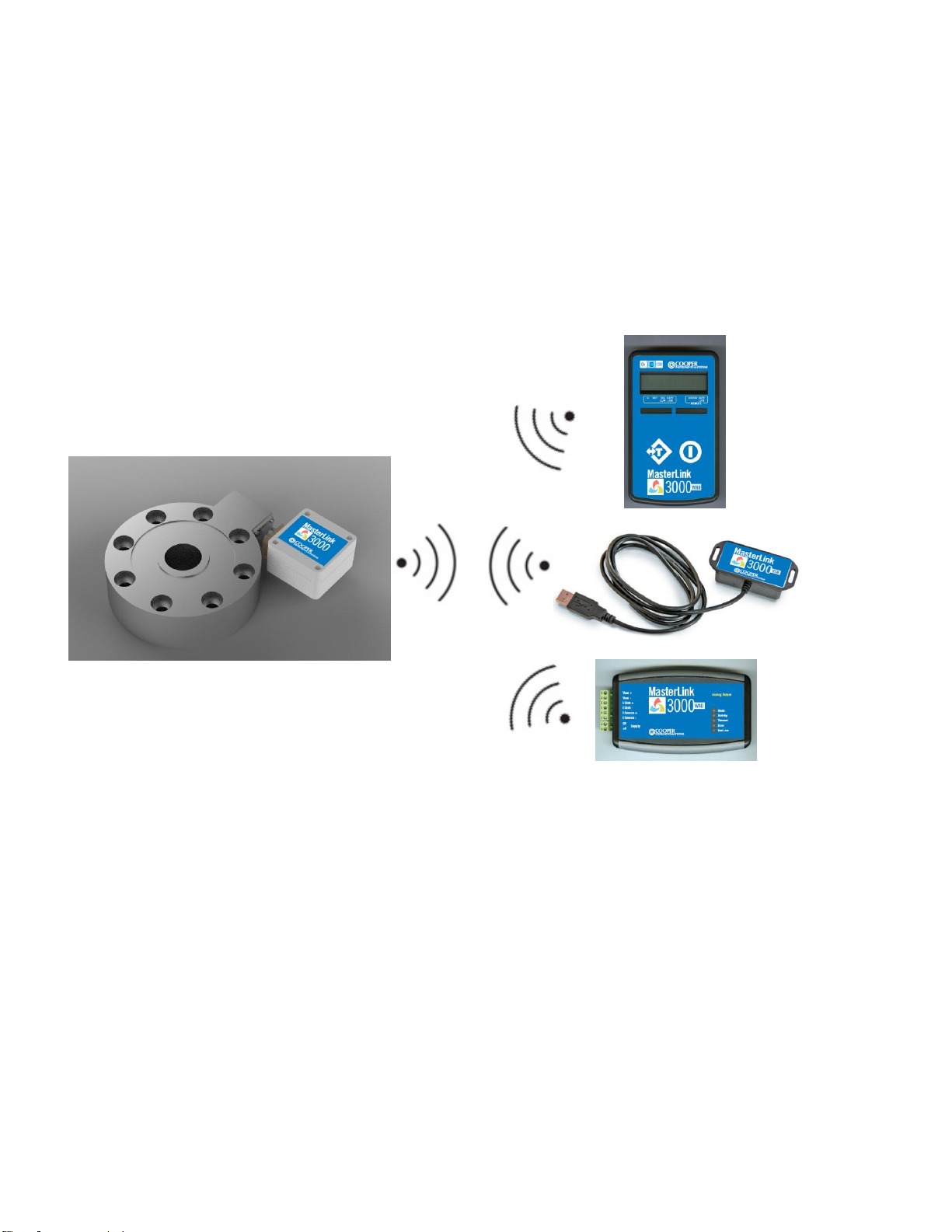
1.0 INTRODUCTION
Handheld Display
USB
Analog Output
The MasterLink 3000 is a stand-alone wireless strain gage device amplifier that is configurable to either a handheld
display, an analog output, or a USB interface.
The MasterLink 3000 software allows for the full configuration of the system. A spectrum analyzer allows the user
to determine an optimal channel selection and signal health can be monitored. A nine point direct input or applied
load calibration is setup through the software and USB device, giving maximum measurement linearity. Battery
voltage of the MasterLink 3000 can be monitored as well. Peak and valley conditions are inherently captured
utilizing the logging capability of the software.
SINGLE DEVICE OR SIMULTANEOUS COMMUNICATION CAPABLE
CF 187 1 RevA
Page 4
2.0 SPECIFICATIONS
2.1 General System Specifications
Modulation Method QPSK
Radio Type Transceiver (2 way)
Data Type 250 Kbits/sec
Radio Frequency 2.4 GHz nominal
Power 1 mW
Available Channels 16
Noise Free Resolution
Sample Time <10 ms 15.5 bits
Sample Time <50 ms 16 bits
Sample Time <100 ms 17.25 bits
Sample Time <1000 ms 18 bits
Maximum Input +/-3.2 mV/V
Excitation Voltage 5 VDC
Range** 150 ft
**Extended Range available
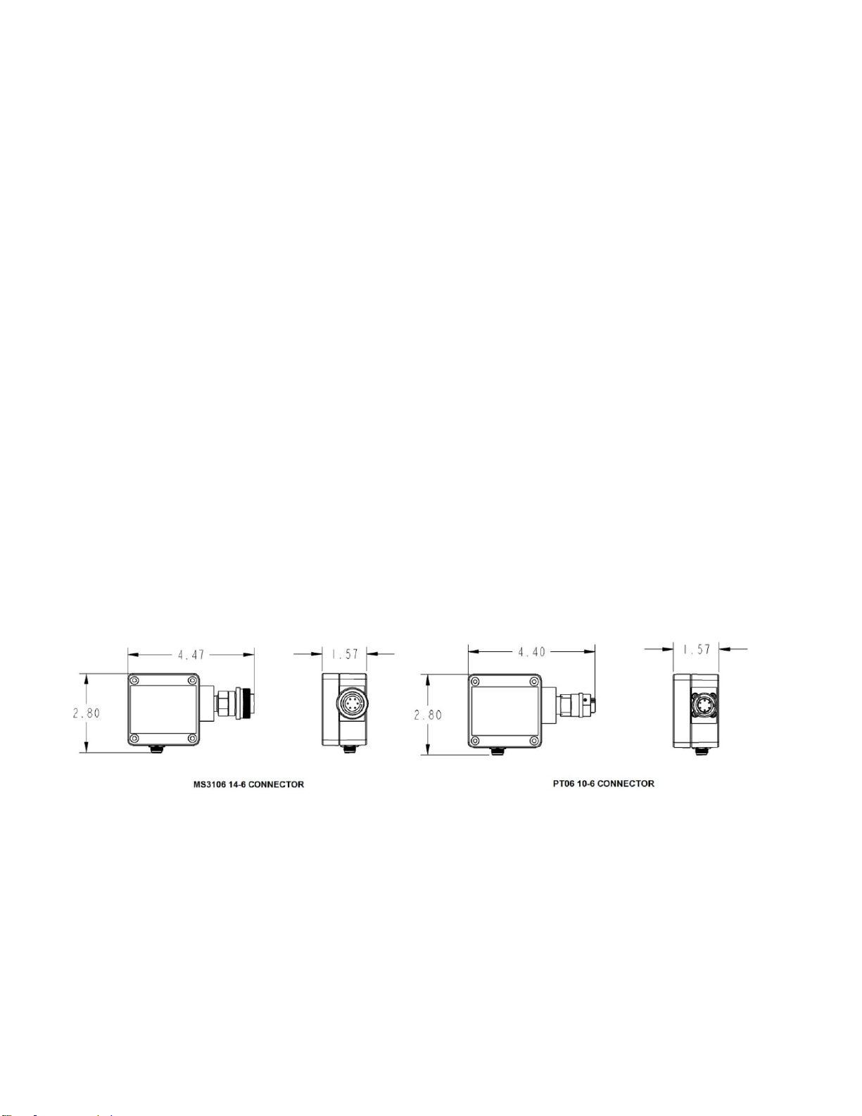
2.1 MasterLink 3000 Amplifier Specifications
IP Rating IP65
Battery Life between charges (3 Hz, Low Power Mode) 450 Hours
Operation Temp -40 to 85 deg C
Weight 7 oz
Optional Connectors
PT06-10-6S
MS3106-14-6S
Dimensions
2.2 MasterLink 3000 Wireless Handheld (WHH) Specifications
Display 8 digit LCD
Channels 1 Standard, 12 Optional
Auto Power on/off of MasterLink 3000 Amplifier
IP Rating IP65
Battery Life
Standby mode (powered off) 1.5 Years
Continuous Operation 40 Hours
Operation Temp -40 to 50 deg C
Dimensions
CF 187 2 RevA
Page 5
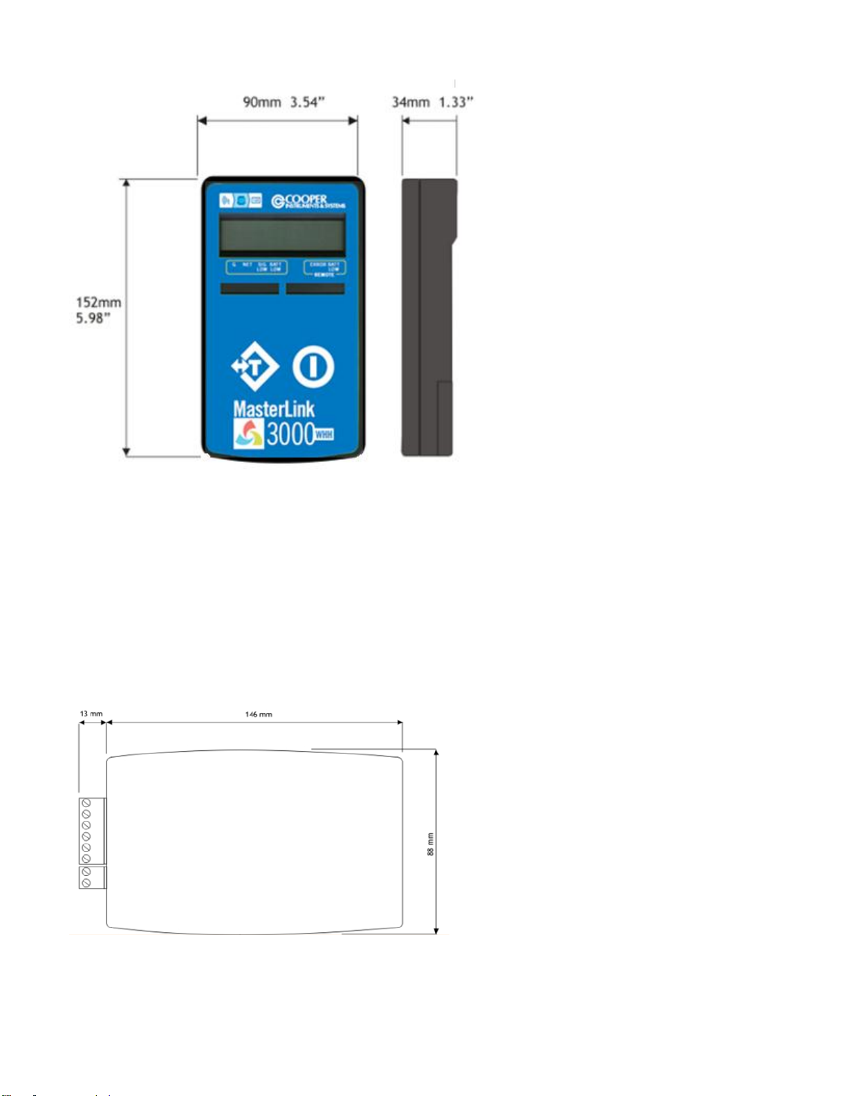
2.3 MasterLink 3000 Wireless Analog Output (WAO) Specifications
Available Outputs 0-10V 4-20mA, 0-20mA, ±10V, ±5V
Update Rate Up to 2000 Hz
Power Supply 9-36 VDC
Range IP65
Desktop Unit 65 ft
Industrial Unit** 150 ft
Operation Temp -40 to 85 deg C
**Extended Range Available
Dimensions
CF 187 3 RevA
Page 6
3.0 SOFTWARE
3.1 System Requirements
Supported Operating Systems – Windows Vista, XP, and 7 32 or 64 bit
USB Port
3.2 T24 Toolkit Software Installation
**It is not necessary to have the MasterLink 3000 amplifier or USB connected to a
computer to install the software
Insert CD into computer and run setup.exe. Follow the prompts to install the software.
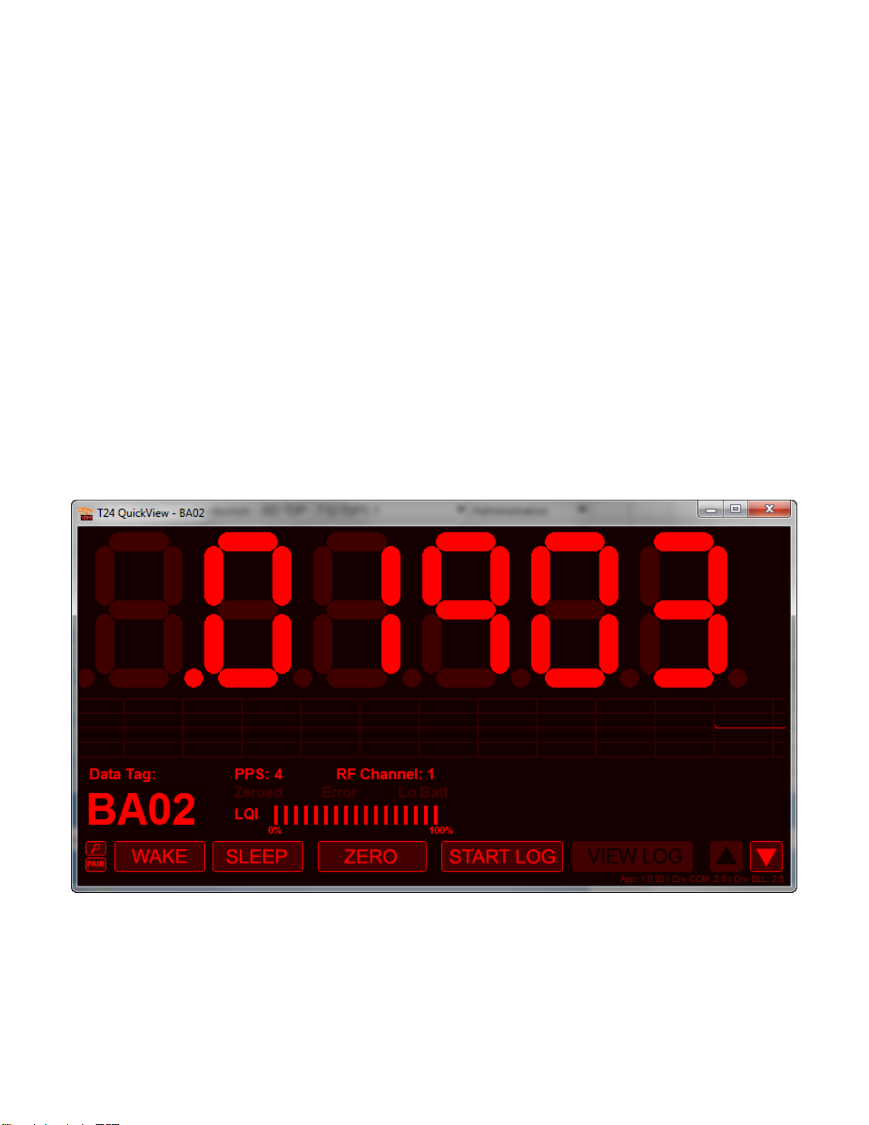
3.3 T24 Quickview Software Installation
**It is not necessary to have the MasterLink 3000 amplifier or USB connected to a computer to
install the software
Insert CD into computer and run setup2.exe. Follow the prompts to install the software.
The Quickview Software is the standard USB viewing and logging software.
The software allows for a remote "wake" or "sleep" of the MasterLink 3000 amplifier to preserve battery power. A
.csv log file is also generated through the "Start Log" command. This .csv file can then be opened in a spreadsheet
program for graphing and other analysis. Battery power and signal integrity can also be monitored utilizing this tool.
CF 187 4 RevA
Page 7
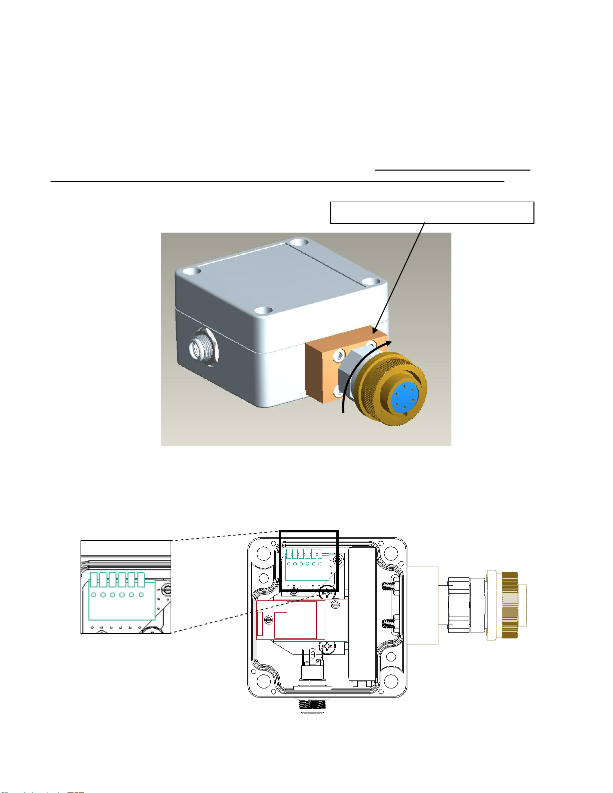
4.0 HARDWARE CONFIGURATION
CONNECTOR PLATE BLOCK
6 5 4 3 2 1
4.1 Connector Alignment
As the MasterLink 3000 has been developed to provide a compact integration to connectorized strain gage
transducers, the connector has the ability to rotate to a desired orientation for the application. The connector
adapter is a pipe thread which screws into the connector plate block. To maintain the IP rating of the system, the
connector must always be tightened into the block and not loosened. In order to tighten the connector, a wrench
must used both on the connector plate block and the connector adapter. If for some reason the connector
needs to be removed, the threads must be cleaned and a new layer of teflon tape must be used.
4.2 Connector Wiring
Pinout:
1 Battery + (RED)
2 Battery - (BLACK)
3 -Excitation
4 -Signal
5 +Signal
6 +Excitation
CF 187 5 RevA
Page 8

5.0 CONFIGURATION AND CALIBRATION VIA TOOLKIT SOFTWARE
**This section is only necessary for changing the default operation characteristics of the
MasterLink 3000 or for calibrating a strain gage transducer to a MasterLink 3000 and linking to
various data display units (DDU). If a system has been purchased, the applicable DDU's have
been setup to the MasterLink 3000 amplifier. The MasterLink 3000 USB unit must be used for
calibration of a strain gage transducer. Cooper Instruments can perform a yearly calibration or
the customer can purchase the USB module to perform in-house calibration.
5.1 Utilizing the Toolkit Software for setting up a MasterLink 3000 amplifier
Goto Start -> Program Files -> T24 Toolkit and click on "T24 Toolkit" in the folder
Upon startup the following screen will be shown
The "Pair" button is used to link the MasterLink 3000 amplifier, the MasterLink 3000 Handheld,
and the MasterLink Analog Output to the MasterLink 3000 USB module. This is a one-time step
necessary to configure the relative device.
**THE TOOLKIT SOFTWARE WILL AUTOMATICALLY CONNECT TO THE USB MODULE AS
LONG AS THE USB MODULE IS CONNECTED TO THE COMPUTER
CF 187 6 RevA
Page 9

To pair the device, rather than disconnecting the internal battery and reconnecting, simply click
on the "click here" link as shown below
This will bring up the screen allowing you to connect to the amplifier using its unique
hexadecimal ID, which can be found engraved onto the amplifier enclosure. Select the "Full
Method" means to connect
CF 187 7 RevA
Page 10
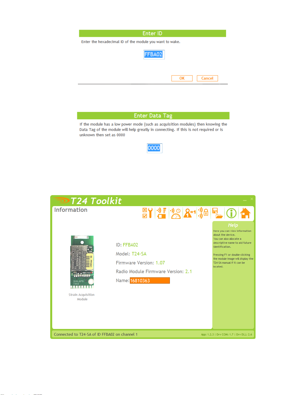
Enter the hexadecimal ID of the amplifier and click "OK". The next prompt is as follows
It is not necessary to enter the data tag, therefore it can be left at 0000.
The next screen brought up will be the amplifier device ID screen
The default name is the S/N of the device, but this is something that could be changed to
something like "LC-Tank 1" at the customer's discretion.
CF 187 8 RevA
Page 11

5.2 Utilizing the Toolkit Software Calibration of device from Calibration Certificate
In some circumstances it may not be possible to apply inputs in which case the calibration can
be entered manually from the calibration table or certificate for a loadcell without ever having to
connect the loadcell.
Items you can change:
Number of Calibration Enter the number of points you wish to calibrate over.
Points In its simplest form you could select two for a linear
calibration. For more complex calibrations which
include linearization select three to nine points.
Input Points 1 – 9 Enter the input point for which you will specify a
(mV/V shown in this required engineering output value
screenshot)
Engineering Units 1 - 9 Enter the required engineering unit output for the
specified input value
Calibrate Click this button to calculate and update the device
calibration
CF 187 9 RevA
Page 12

5.2 Utilizing the Toolkit Software Calibration of device with applied loading
Here you can calibrate the acquisition module and set a system zero if required. This simple
page allows semi-automated calibration where you can apply known inputs to calibrate.
This calibration includes linearization and is automatically applied
Calibration Process
Decide on how many points you will calibrate over.
Decide what inputs will be applied (in ascending order) at each point.
Enter the actual input (in the required units) that you want the module to read at each
point.
Now proceed to apply each input in turn (allowing a settle time) and click the Acquire
button at that point. You can now apply the next input and click Acquire until all the
points are completed.
The bottom of the page shows the Input Value and the Calibrated Value. Once the second
point has been acquired this Calibrated Value should display the actual calibrated value.
5.3 Utilizing the Toolkit Software to save/restore the overall and calibration settings to a
configuration file
Here you can save the device settings to a file on your PC so that they can be later loaded back
into the same or different device.
CF 187 10 RevA
Page 13

6.0 HANDHELD DEVICE
6.1 Connecting Power
Remove the two screws on the rear battery compartment. Insert two alkaline AA batteries. Refit
the battery compartment cover. The handheld device is now switched on so should be turned off
until the acquisition module is ready. To turn off just hold down the power key until the display
shows BUSY then release it.
6.2 Using Toolkit Software to setup Device
*Follow steps in section 5.1 to connect to handheld device.
CF 187 11 RevA
Page 14

Items you can change:
Power On Auto Zero Here you can determine whether the device performs
automatic zero when it is powered on.
Enter zero to disable this function.
If you enter a non-zero value then when the handheld
is first turned on it checks the value read from the
acquisition module. If this falls within ± of this value
then the display will be altered so this reads zero.
In its simplest form you could select two for a linear
calibration. For more complex calibrations which
include linearization select three to nine points.
Zero Indication Band Using this setting you can mask tiny changes in input
after you press the Tare button.
Entering zero will disable this function.
Entering a non-zero value will provide a band within
which the display will always read zero.
Once the reading exceeds this value the real weight
will be displayed as no taring is taking place.
CF 187 12 RevA
Page 15

Items you can change:
Format & Resolution Here you can define how the values are displayed on
the LCD. There are 7 digits available and you can
define where the decimal point is shown by entering
text where a zero indicates a numeric digit position.
When the data is being displayed the number of
decimal places you define may be overridden as the
display will always show the correct number of integer
digits. Example: If you set the format to 000.0000 and
the value to display is 1000.1234 the display will show
1000.123
You can also define the resolution, which is the block
size of changes to the display.
Example: If you enter the format as 000.0005 the
display will only change in steps of .0005 which can be
used to mask noisy digits at high resolutions.
Leading Zero This can be turned on or off and will suppress leading
Suppression zeroes when on.
Example: If the display reads 000.123 with leading zero
suppression turned off it will display 0.123 when turned
on.
CF 187 13 RevA
Page 16

Overload Limit You can enter a limit here above which Overload will
be shown on the display instead of the actual value.
Enter zero to disable this feature.This can be turned on
or off and will suppress leading zeroes when on.
Timeout Enter the timeout in seconds. This sets the time
allowed without any data arriving from the viewed
module before all dashes are displayed on the LCD.
Should be at least 3 times the interval between the
data being transmitted by the acquisition module.
6.3 Connecting to the MasterLink 3000 Amplifier using Toolkit
Paired Data Tag and Paired ID of the MasterLink 3000 amplifier need to be entered into these
fields. These correspond to the Data Tag and ID of the MasterLink 3000 amplifier.
CF 187 14 RevA
Page 17

7.0 ANALOG OUTPUT
7.1 Connecting Power
You will need to connect a power supply to the device for it to operate and to enable
configuration using a base station and the appropriate toolkit software. Power is supplied via the
screw terminals and can be in the range of 9 to 36V DC.
7.2 I/O Connection and DIP Switch Settings
CF 187 15 RevA
Page 18

7.3 Using Toolkit Software to setup Device
*Follow steps in section 5.1 to connect to analog amplifier.
Items you can change:
Input
In Minimum Enter the input value that should result in the minimum
output. The minimum output depends on the Current
Selected Output which is determined by the SW2 DIP
switch settings.
CF 187 16 RevA
Page 19
In maximum Enter the input value that should result in the maximum
output. The maximum output depends on the Current
Selected Output which is determined by the SW2 DIP
switch settings.
Input value This shows the currently supplied value to the device.
An active acquisition module must be in place to
view this value.
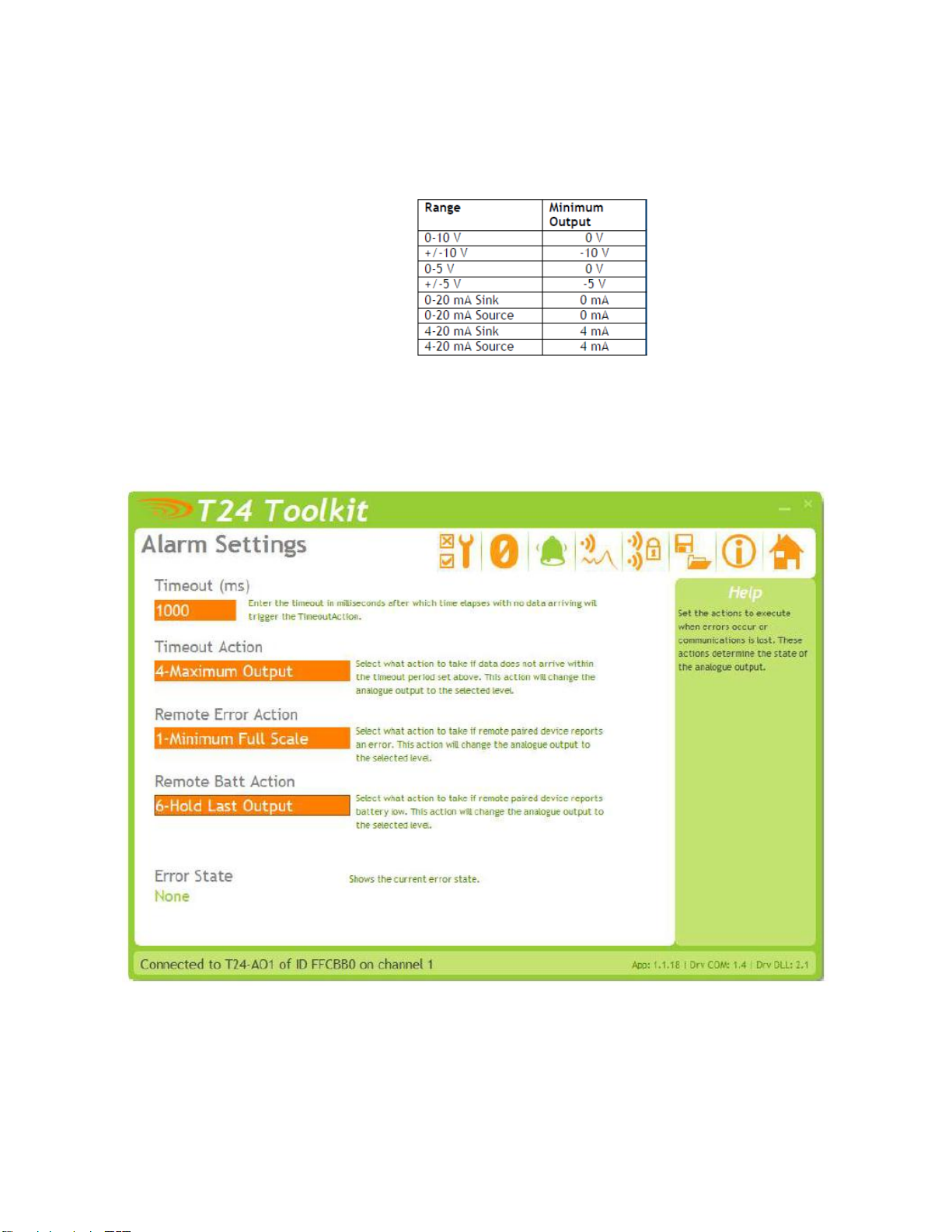
Here you can set the action to take when certain errors occur.
The actions are applied when the errors occur and if more than one error is present the actions
are applied with the following priorities: Timeout Action, Remote Error Action, Remote Batt
Action
When errors are removed the analog output resumes reflecting the current input.
CF 187 17 RevA
Page 20

Items you can change:
Timeout Enter the timeout in milliseconds for the input to
timeout. If a new Data Provider packet does not arrive
within this time the Timeout Action will trigger.
Generally this timeout should be set to at least three
times the acquisition module transmission rate.
Timeout Action Select the action to take place when a timeout occurs.
i.e. when communications (for more than the duration
of the Timeout value) is lost with the acquisition
module.
See the Output Actions section for the available
actions and the effect of these choices on the different
output ranges.
Remote Error Action Acquisition modules can report errors.
See the Output Actions section for the available
actions and the effect of these choices on the different
output ranges.
Remote Batt Action When the acquisition module reports a low battery this
action will occur. See the Output Actions section for
the available actions and the effect of these choices on
the different output ranges.
Output Actions
The following actions can be selected.
None Do nothing
Minimum Full Scale Set analog output to the minimum full scale value
Maximum Full Scale Set analog output to the maximum full scale value
Minimum Output Set analog output to the minimum possible value
Maximum Output Set analog output to the maximum possible scale value
Half Full Scale Set analog output to halfway between minimum and
maximum full scale value
Hold Last Output Hold the last output. (Does the same as None for the
Timeout Action)
CF 187 18 RevA
Page 21

WARRANTY REPAIR POLICY
Limited Warranty On Products
Any Cooper Instruments product which, under normal operating conditions, proves defective in material or in
workmanship within one year of the date of shipment by Cooper will be repaired or replaced free of charge provided
that a return material authorization is obtained from Cooper and the defective product is sent, transportation
charges prepaid, with notice of the defect, and it is established that the product has been properly installed,
maintained, and operated within the limits of rated and normal usage. Replacement or repaired product will be
shipped F.O.B. from our plant. The terms of this warranty do not extend to any product or part thereof which, under
normal usage, has an inherently shorter useful life than one year. The replacement warranty detailed here is the
buyer’s exclusive remedy, and will satisfy all obligations of Cooper whether based on contract, negligence, or
otherwise. Cooper is not responsible for any incidental or consequential loss or damage which might result from a
failure of any and all other warranties, express or implied, including implied warranty of merchantability or fitness for
particular purpose. Any unauthorized disassembly or attempt to repair voids this warranty.
Obtaining Service Under Warranty
Advance authorization is required prior to the return to Cooper Instruments. Before returning the item, contact the
Repair Department c/o Cooper Instruments at (540) 349-4746 for a Return Material Authorization number.
Shipment to Cooper shall be at buyer’s expense and repaired or replacement items will be shipped F.O.B. from our
plant in Warrenton, Virginia. Non-verified problems or defects may be subject to a $150 evaluation charge. Please
return the original calibration data with the unit.
Repair Warranty
All repairs of Cooper products are warranted for a period of 90 days from date of shipment. This warranty applies
only to those items that were found defective and repaired; it does not apply to products in which no defect was
found and returned as is or merely recalibrated. It may be possible for out-of-warranty products to be returned to
the exact original specifications or dimensions.
* Technical description of the defect: In order to properly repair a product, it is absolutely necessary for Cooper to
receive information specifying the reason the product is being returned. Specific test data, written observations on
the failure and the specific corrective action you require are needed.
CF 187 19 RevA
 Loading...