

Page 1

Series 2
DIGITAL FORCE GAUGES
User’s Guide
Page 2
Series 2 Digital Force Gauges User’s Guide
Thank you…
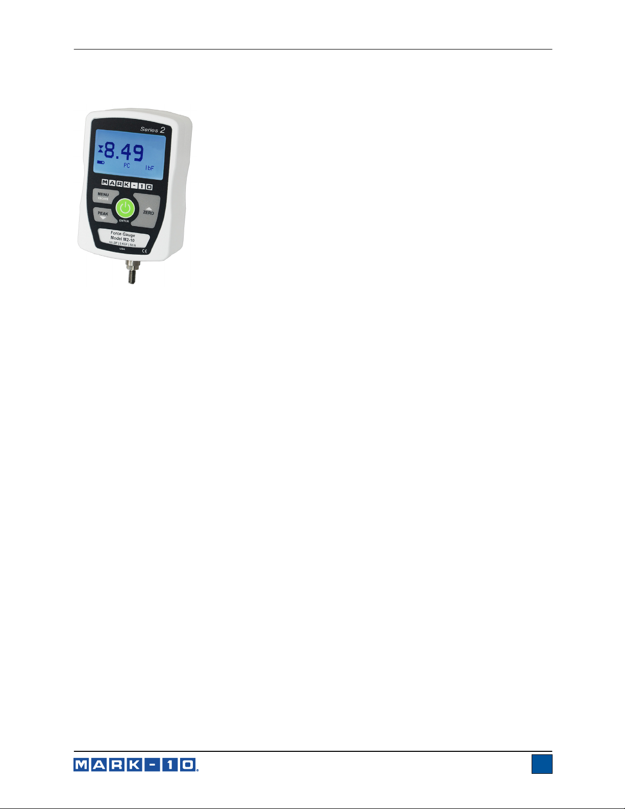
Thank you for purchasing a Mark-10 Series 2 digital force gauge, designed
for tension and compression force testing applications from 2 to 100 lbF (10
to 500 N) full scale. The Series 2 is an essential component of a force
testing system, typically also comprising a test stand and grips.
With proper usage, we are confident that you will get many years of great
service with this product. Mark-10 force gauges are ruggedly built for many
years of service in laboratory and industrial environments.
This User’s Guide provides setup, safety, and operation instructions.
Dimensions and specifications are also provided. For additional information
or answers to your questions, please do not hesitate to contact us. Our
technical support and engineering teams are eager to assist you.
Before use, each person who is to use the Series 2 force gauge should
be fully trained in appropriate operation and safety procedures.
TABLE OF CONTENTS
OVERVIEW .........................................................2
POWER ...............................................................3
MECHANICAL SETUP .......................................4
HOME SCREEN AND CONTROLS ...................6
OPERATING MODES .........................................7
CHANGING THE UNITS .....................................7
DIGITAL FILTERS ..............................................8
CALIBRATION ...................................................8
OTHER SETTINGS ...........................................12
SPECIFICATIONS ............................................14
1
Page 3
Series 2 Digital Force Gauges User’s Guide
1 OVERVIEW
1.1 List of included items
Qty. Description
1 Digital force gauge
1 9V battery (inside the gauge)
1 Resource CD
1.2 List of optional items
Part No. Description
12-1049 Carrying case
AC1030 AC adapter, 110V US
AC1031 AC adapter, 220V Euro
AC1032 AC adapter, 220V UK
AC1035 AC adapter, 220V, Australian
CERT
G1038
G1039
G1029
G1026
G1025
G1027
G1024
1.3 Safety / Proper Usage
Certificate of calibration with data
Medium hook, #10-32M (requires G1039)
Coupling, #10-32F/F
Flat head, #10-32F
Cone, #10-32F
Chisel point, #10-32F
V-groove, #10-32F
Extension rod, 5”, #10-32F
Caution!
Note the force gauge’s capacity before use and ensure that the capacity is not exceeded.
Producing a force greater than 150% of the gauge’s capacity can damage the internal load cell. An
overload can occur whether the gauge is powered on or off.
Typical materials able to be tested include many manufactured items, such as springs, electronic
components, fasteners, caps, films, mechanical assemblies, and many others. Items that should not be
used with the gauge include potentially flammable substances or products, items that can shatter in an
unsafe manner, and any other components that can present an exceedingly hazardous situation when
acted upon by a force.
The following safety checks and procedures should be performed before and during operation:
1. Never operate the gauge if there is any visible damage to the AC adapter or the gauge itself.
2. Ensure that the gauge is kept away from water or any other electrically conductive liquids at all
times.
3. The gauge should be serviced by a trained technician only. AC power must be disconnected and
the gauge must be powered off before the housing is opened.
4. Always consider the characteristics of the sample being tested before initiating a test. A risk
assessment should be carried out beforehand to ensure that all safety measures have been
addressed and implemented.
2
Page 4
Series 2 Digital Force Gauges User’s Guide
5. Wear eye and face protection when testing, especially when testing brittle samples that have the
potential to shatter under force. Be aware of the dangers posed by potential energy that can
accumulate in the sample during testing. Extra bodily protection should be worn if a destructive
failure of a test sample is possible.
6. In certain applications, such as the testing of brittle samples that can shatter, or other applications
that could lead to a hazardous situation, it is strongly recommended that a machine guarding
system be employed to protect the operator and others in the vicinity from shards or debris.
7. When the gauge is not in use, ensure that the power is turned off.
2 POWER
Caution!
Do not use AC adapters or batteries other than supplied or instrument damage may occur.
The gauge is powered either by a 9V non-rechargeable battery or by an AC adapter (input jack is located
in the left side of the housing).
If the AC adapter is plugged in, an icon appears in the lower left corner of the display, as follows:
If the AC adapter is not plugged in, battery power drainage is denoted in a five-step process:
1. When battery life is greater than 75%, the following indicator is present:
2. When battery life is between 50% and 75%, the following indicator is present:
3. When battery life is between 25% and 50%, the following indicator is present:
4. When battery life is less than 25%, the following indicator is present:
5. When battery life drops to approximately 2%, the indicator from step 4 will be flashing.
Several minutes after (timing depends on usage and whether the backlight is turned on or
off), a message will appear, “BATTERY VOLTAGE TOO LOW. POWERING OFF”, and the
gauge will then power off.
The gauge can be configured to automatically power off following a period of inactivity. Refer to the Other
Settings section for details.
3
Page 5
Series 2 Digital Force Gauges User’s Guide
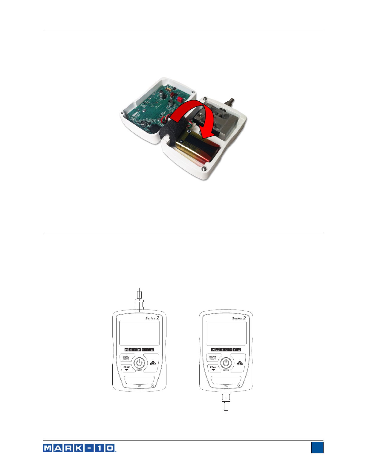
Battery life is approximately 24 hours with the backlight on, or 92 hours with the backlight off. To change
the battery, loosen the two captive screws on the back side of the housing and separate the two housing
halves. A foam strip separates the battery from the PCB, as shown in the illustration below:
Ensure that the foam is positioned above the battery when reassembling the housing. Exercise care when
reassembling the two halves of the housing, ensuring that internal wires do not interfere.
3 MECHANICAL SETUP
3.1 Loading shaft orientation
In order to accommodate a variety of testing requirements, the orientation of the loading shaft may be
oriented in either of the two positions shown below. In order to change the loading shaft orientation,
loosen the two captive screws on the back side of the housing, separate the two housing halves, rotate
one half 180 degrees, and reassemble. Exercise care when reassembling the two halves of the housing,
ensuring that internal wires do not interfere.
Load cell shaft up Load cell shaft down
4
Page 6
Series 2 Digital Force Gauges User’s Guide
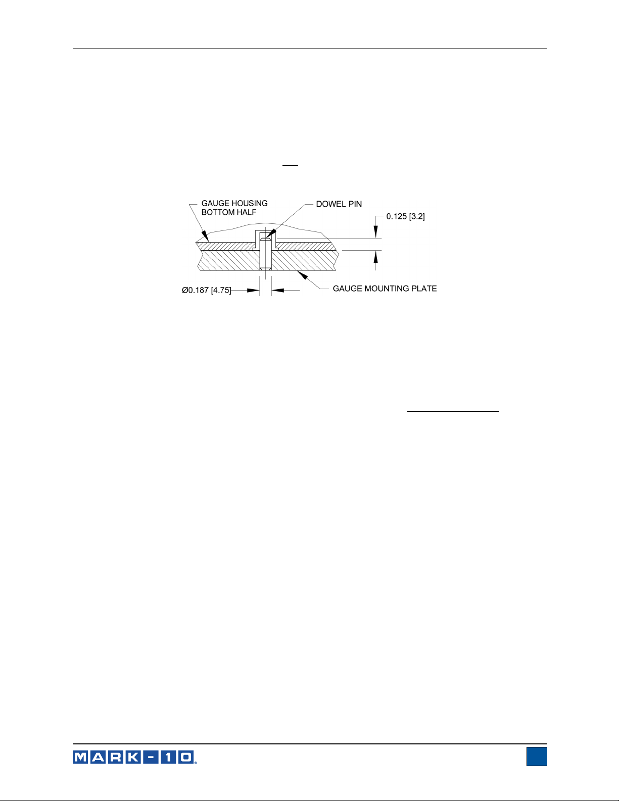
3.2 Mounting to a plate
Although the gauge may be used by hand, proper mounting is important if attached to a fixture or test
stand. The round steel insert with a hole in the back of the housing is provided to withstand the load
during a test. A mating dowel pin should be used (see illustration below). Mounting plates on Mark-10 test
stands include a dowel pin and clearance holes for the four threaded holes located near the corners of
the housing. An additional two holes are supplied for metric screws. These holes are designed to
accommodate screws in order to hold the gauge in place (Mark-10 test stands include a set of thumb
screws for gauge mounting). The screws must not
be used for load bearing purposes. Failure to use a
dowel pin properly can result in a hazardous situation.
3.3 Mounting attachments to the gauge
The force gauge’s threaded loading shaft is designed to accommodate common grips and attachments
with female mounting holes. To mount a grip, gently thread it onto the shaft. Ensure that the grip or fixture
is positioned to ensure axial load with respect to the loading shaft of the force gauge. When using a grip,
ensure that it secures the sample in such a way that it is prevented from slipping out during a test,
preventing a potential safety risk to the operator and others in the vicinity. If using a grip or fixture from a
supplier other than Mark-10, ensure that it is constructed of suitably rugged materials and components.
Do not use jam nuts or tools to tighten grips or attachments onto the shaft. Finger-tighten only
.
5
Page 7

Series 2 Digital Force Gauges User’s Guide
4 HOME SCREEN AND CONTROLS
4.1 Home Screen
5
4
No. Name Description
1 Primary reading
2 Units
3 Mode
4 Battery / AC
adapter indicator
5 Tension /
compression
indicator
4.2 Controls
The current displayed force reading. See Operating Modes section for
details.
The current measurement unit. Abbreviations are as follows:
lbF – Pound-force
kgF – Kilogram-force
N – Newton
The current measurement mode. Abbreviations are as follows:
RT – Real Time
PC – Peak Compression
PT – Peak Tension
See Operating Modes section for details about each of these modes
Either the AC adapter icon or battery power icon will be shown, depending on
power conditions. Refer to the Power section for details.
- indicates a compression (push) direction
- indicates a tension (pull) direction
23
1
Primary
Label Primary Function
ZERO
MENU
PEAK
Note: Measurement units are configured through the menu. Refer to Section 6 for details.
Powers the gauge on and off. Press
briefly to power on, press and hold
to power off. Active only when the
home screen is displayed.
Zeroes the primary reading.
Enters the main menu.
Toggles between real-time and peak
measurement modes.
Secondary
Label Secondary Function
ENTER
(UP)
ESCAPE
(DOWN)
Various uses, as described in the
following sections.
Navigates up through the menu and
sub-menus.
Reverts one step backwards through
the menu hierarchy.
Navigates down through the menu
and sub-menus.
6
Page 8

Series 2 Digital Force Gauges User’s Guide
4.3 Menu navigation basics
Most of the gauge’s various functions and parameters are configured through the main menu. To access
the menu press MENU. Use the UP and DOWN keys to scroll through the items. The current selection is
denoted with clear text over a dark background. Press ENTER to select a menu item, then use UP and
DOWN again to scroll through the sub-menus. Press ENTER again to select the sub-menu item.
For parameters that may be either selected or deselected, press ENTER to toggle between selecting and
deselecting. An asterisk (*) to the left of the parameter label is used to indicate when the parameter has
been selected.
For parameters requiring the input of a numerical value, use the UP and DOWN keys to increment or
decrement the value. Press and hold either key to auto-increment at a gradually increasing rate. When
the desired value has been reached, press ENTER to save the change and revert back to the sub-menu
item, or press ESCAPE to revert back to the sub-menu item without saving. Press ESCAPE to revert one
step back in the menu hierarchy until back into normal operating mode.
Refer to the following sections for details about setting up particular functions and parameters.
5 OPERATING MODES
Caution!
In any operating mode, if the capacity of the instrument has been exceeded by more than 110%,
the display will show “OVER” to indicate an overload.
Three operating modes are possible with Series 2 gauges. To cycle between the modes, press PEAK
while in the home screen.
5.1 Real time (RT)
The primary reading corresponds to the live measured reading.
5.2 Peak Compression (PC)
The primary reading corresponds to the peak compression reading observed. If the actual force
decreases from the peak value, the peak will still be retained in the primary reading area of the display.
Pressing ZERO will reset the value.
5.3 Peak Tension (PT)
Same as Peak Compression, but for tension readings.
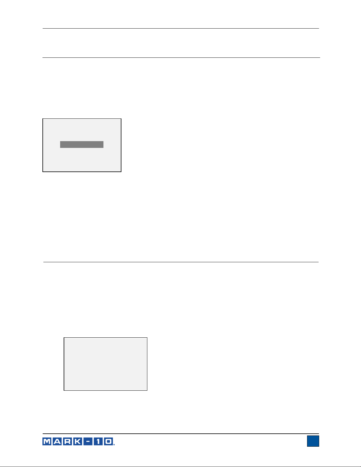
6 CHANGING THE UNITS
Series 2 gauges display one of three measurement units. To change the unit, select Units from the
menu. The display will appear as follows:
UNITS
* lbF
kgF
N
The gauge will always power on with the unit selected.
7
Page 9
Series 2 Digital Force Gauges User’s Guide
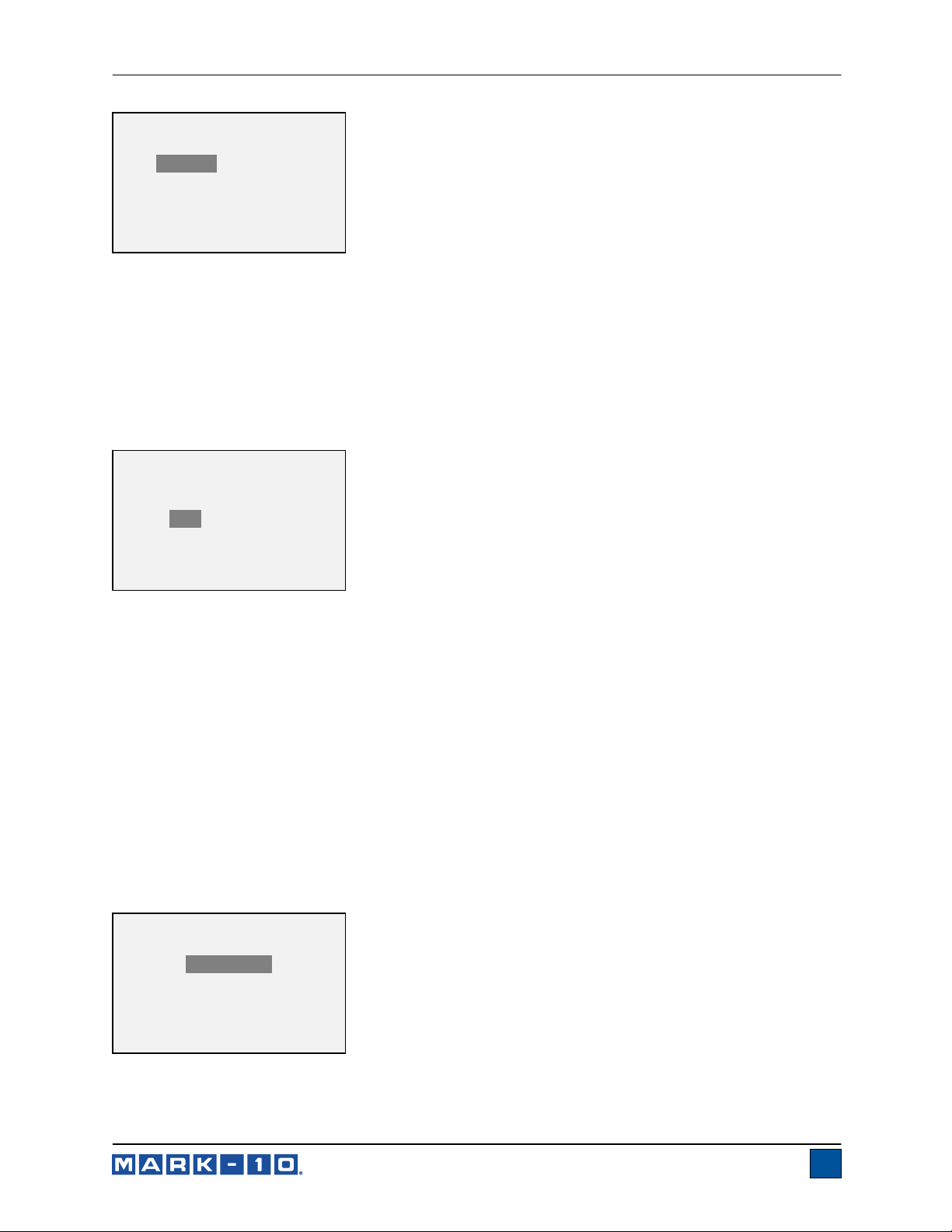
7 DIGITAL FILTERS
Digital filters are provided to help smooth out the readings in situations where there is mechanical
interference in the work area or test sample. These filters utilize the moving average technique in which
consecutive readings are pushed through a buffer and the displayed reading is the average of the buffer
contents. By varying the length of the buffer, a variable smoothing effect can be achieved. The selection
of 1 will disable the filter since the average of a single value is the value itself.
To access digital filter settings, select Filters from the menu. The display will appear as follows:
DIGITAL FILTERS
(1 = Fastest)
Current Reading
8
Displayed Reading
1024
Two filters are available:
Current Reading – Applies to the peak capture rate of the instrument.
Displayed Reading – Applies to the primary reading on the display.
Available settings: 1,2,4,8,16,32,64,128,256,512,1024. It is recommended to keep the current reading
filter at its lowest value for best performance, and the displayed reading filter at its highest value for best
stability.
8 CALIBRATION
8.1 Initial Physical Setup
The gauge should be mounted vertically to a test stand or fixture rugged enough to withstand a load
equal to the full capacity of the instrument. Certified deadweights or master load cells should be used,
along with appropriate mounting brackets and fixtures. Caution should be taken while handling such
equipment.
8.2 Calibration Procedure
1. Select Calibration from the menu. The display will appear as follows:
CALIBRATION
To invert the
display, press the
DIRECTION key.
THEN PRESS ENTER
2. Press DIRECTION to invert the display, if desired. ENTER to continue. The display will appear as
follows:
8
Page 10

Series 2 Digital Force Gauges User’s Guide
CALIBRATION
ENTER # CAL POINTS
(1 TO 10)
COMPRESSION:
5
TENSION :
5
The gauge can be calibrated at up to 10 points in each direction. Enter the number of calibration
points for each direction (compression and tension). At least one point must be selected for each
direction.
Note: To achieve the accuracy specification of ±0.5%, it is recommended to calibrate the gauge
at 5 or more even increments in both the tension and compression directions. For example, a
gauge with capacity of 10 lbF should be calibrated at 2, 4, 6, 8, and 10 lb loads in each direction.
3. To escape the Calibration menu at any time, press ESCAPE. The display will appear as follows:
CALIBRATION
NOT COMPLETE
CANCEL
EXIT W/O SAVING
Selecting “CANCEL” will revert back to the Calibration setup. Selecting “EXIT W/O SAVING” will
return to the menu without saving changes.
4. After the number of calibration points has been entered, press ENTER. The display will appear as
follows:
CALIBRATION
OFFSET
Place force gauge
horizontal
THEN PRESS ZERO
5. Place the force gauge horizontally on a level surface free from vibration, then press ZERO. The
gauge will calculate offsets, and the display will appear as follows:
CALIBRATION
OFFSET
Please wait…
9
Page 11

Series 2 Digital Force Gauges User’s Guide
CALIBRATION
CALIBRATION
OFFSET
Sen.Offset Adj.Passed
Ana.Offset Adj.Passed
Sen.Offset Adj.Failed
Ana.Offset Adj.Failed
If failed:
6. The following screen appears after the offsets have been calculated:
CALIBRATION
COMPRESSION
Attach necessary
weight fixtures.
THEN PRESS ENTER
Attach weight fixtures (brackets, hooks, etc), as required. Do not yet attach any weights or apply
any calibration loads. Then press ENTER.
7. The display will appear as follows:
CALIBRATION
COMPRESSION
Optionally exercise
load cell a few times.
THEN PRESS ENTER
Optionally exercise the load cell shaft several times (at full scale, if possible), then press ENTER.
8. The display will appear as follows:
CALIBRATION
COMPRESSION
GAIN ADJUST
APPLY FULL SCALE LOAD
10.000 LBF +/-20%
THEN PRESS ENTER
OFFSET
Apply a weight equal to the full scale of the instrument, and then press ENTER.
9. After displaying “PLEASE WAIT…” the display will appear as follows:
CALIBRATION
COMPRESSION
ENSURE NO LOAD
THEN PRESS ZERO
Remove the load applied in Step 8, leave the fixtures in place, then press ZERO.
10
Page 12

Series 2 Digital Force Gauges User’s Guide
10. The display will appear as follows:
CALIBRATION
COMPRESSION
APPLY LOAD
1 OF 5
ENTER LOAD:
2.000 LBF
THEN PRESS ENTER
Use the UP and DOWN keys to adjust the load value as required. The load values default to even
increments, as indicated by the previously entered number of data points (even increments are
recommended for best results). For example, if a 50 lbF capacity gauge is calibrated, and 5 data
points were selected, the load values will default to 10, 20, 30, 40, and 50 lb. Apply the
calibration load. Then press ENTER.
Repeat the above step for the number of data points selected.
11. After all the compression calibration points have been completed, the display will appear as
follows:
CALIBRATION
COMPRESSION COMPLETE
REVERSE DIRECTION
FOR TENSION
Attach necessary
weight fixtures.
THEN PRESS ENTER
Press ENTER.
12. The display will appear as follows:
CALIBRATION
To invert the
display, press the
DIRECTION key.
THEN PRESS ENTER
Reverse the orientation of the load cell shaft by rotating the gauge 180 degrees. Press
DIRECTION to invert the display. Then attach weight fixtures. The following screens will step
through the same procedure as with the compression direction. Proceed in the same manner.
13. At the completion of the tension calibration, the display will appear as follows:
CALIBRATION
COMPLETE
SAVE & EXIT
EXIT W/O SAVING
11
Page 13

Series 2 Digital Force Gauges User’s Guide
To save the calibration information, select “SAVE & EXIT”. To exit without saving the data select
“EXIT W/O SAVING”.
14. Any errors are reported by the following screens:
CALIBRATION
Units must be gF.
PLEASE TRY AGAIN
PRESS ENTER
Displayed at the start of calibration if a disallowed unit is selected.
LOAD NOT STABLE
PLEASE TRY AGAIN
Ensure that the load is not swinging, oscillating, or vibrating in any manner. Then try again.
CALIBRATION
COMPRESSION
LOAD TOO LOW
PLEASE TRY AGAIN
The calibration weight does not match the set value.
CALIBRATION
TENSION
LOAD TOO CLOSE
TO PREVIOUS
PLEASE TRY AGAIN
The entered calibration point is too close to the previous point.
9 OTHER SETTINGS
9.1 Automatic Shutoff
The gauge may be configured to automatically power off following a period of inactivity while on battery
power. Inactivity is defined as the absence of any key presses or load changes of 100 counts or less. To
access these settings, select Automatic Shutoff from the menu. The display will appear as follows:
12
Page 14
Series 2 Digital Force Gauges User’s Guide
AUTOMATIC SHUTOFF
* Disabled
Enabled
Set Minutes
5
Select Disabled to disable automatic shutoff. Select Enabled to enable it. The length of time of inactivity
is programmed in minutes via the Set Minutes parameter. Available settings: 5-30, in 5 minute
increments.
Note: If the AC adapter is plugged in, the gauge will ignore these settings and remain powered on until
the POWER key is pressed.
9.2 Backlight
Several initial settings are available, upon powering on the gauge. To access these settings, select
Backlight from the menu. The display will appear as follows:
BACKLIGHT
Off
On
* Auto
Set Minutes
1
Select Off for the backlight to be off upon powering on the gauge.
Select On for the backlight to be on upon powering on the gauge.
Select Auto for the backlight to be on upon powering gauge, but will shut off after a period of inactivity (as
defined in the Automatic Shutoff sub-section). The backlight will turn on again when activity resumes.
The length of time of inactivity is programmed in minutes via the Set Minutes parameter. Available
settings: 1-10, in 1 minute increments.
Note: If the AC adapter is plugged in, the gauge will ignore these settings and keep the backlight on.
Selecting the On or Off setting in the Backlight menu will manually turn the backlight on or off as if the
Backlight key were pressed.
9.3 LCD Contrast
The contrast of the display may be adjusted. Select LCD Contrast from the menu. The screen will appear
as follows:
LCD CONTRAST
Set Contrast
10
Press ENTER to modify the contrast. Select a value from 0 to 25, 25 producing the most contrast.
13
Page 15

Series 2 Digital Force Gauges User’s Guide
9.4 Initial Mode
This section is used to configure the initial mode upon powering on the gauge. To access this parameter,
select Initial Mode from the menu. The screen will appear as follows:
INITIAL MODE
* Real Time
Peak Compression
Peak Tension
The default value is Real Time.
9.5 Information / Welcome Screen
The following screen is displayed at power up and can be accessed at any time by selecting Information
from the menu:
Digital Force Gauge
Series 2
Model No: M2-50
Serial No: 1234567
Version: 1.0
(c) Mark-10 Corp.
10 SPECIFICATIONS
10.1 General
Accuracy:
Sampling rate:
Power:
Battery life:
Safe overload:
Weight:
Included items:
Load cell deflection:
Environmental
requirements:
Warranty:
±0.5% of full scale
500 Hz
AC or 9V non-rechargeable battery, with multi-step low battery indicator
Backlight on:
Backlight off:
150% of full scale (display shows “OVER” at 110% and above)
0.7 lb [0.33 kg]
9V battery, quick-start guide, resource CD, certificate of conformance
0.010 in [0.25 mm]
40 - 100°F, max. 96% humidity, non-condensating
3 years (see individual statement for further details)
up to 24 hours of continuous use
up to 92 hours of continuous use
14
Page 16

Series 2 Digital Force Gauges User’s Guide
10.3 Capacity & Resolution
Model
M2-2
M2-5
M2-10
M2-20
M2-50
M2-100
lbF kgF N
2 x 0.002 1 x 0.001 10 X 0.01
5 x 0.005 2.5 x 0.002 25 x 0.02
10 x 0.01 5 x 0.005 50 x 0.05
20 x 0.02 10 x 0.01 100 x 0.1
50 x 0.05 25 x 0.02 250 x 0.2
100 x 0.1 50 x 0.05 500 x 0.5
10.4 Dimensions
IN [MM]
15
Page 17

Series 2 Digital Force Gauges User’s Guide
Mark-10 Corporation has been an innovator in the force and torque measurement fields
since 1979. We strive to achieve 100% customer satisfaction through excellence in product
design, manufacturing and customer support. In addition to our standard line of products we
can provide modifications and custom designs for OEM applications. Our engineering team
is eager to satisfy any special requirements. Please contact us for further information or
suggestions for improvement.
We make a measurable difference in force and torque measurement
Mark-10 Corporation
11 Dixon Avenue
Copiague, NY 11726 USA
1-888-MARK-TEN
Tel: 631-842-9200
Fax: 631-842-9201
Internet: www.mark-10.com
E-mail: info@mark-10.com
16
32-1168
1012
 Loading...