

Page 1

LXT 980 and LXT 981
TORQUE SENSOR
USER’S GUIDE
www.cooperinstruments.com
PH: (540) 349-4746 • FAX: (540) 347-4755
Page 2

CONTENTS
1.0 INTRODUCTION ..................................................................................................................................................................................... 3
2.0 MODEL LXT 980 / LXT 981 ................................................................................................................................................................... 3
3.0 TECHNICAL CHARACTERISTICS OF THE SENSOR ................................................................................................................. 4
4.0 VERSIONS AND ORDE R OPTI ONS ................................................................................................................................................... 5
5.0 AVAILABLE OPTIONS .......................................................................................................................................................................... 6
5.1 Optional Signal Outputs ...................................................................................................................................... 6
5.2 Optical angle sensor ........................................................................................................................................... 6
6.0 DIMENSIONS ............................................................................................................................................................................................ 7
7.0 CONNECTION PLAN .............................................................................................................................................................................. 9
8.0 OPERATING INSTRUCTIONS ............................................................................................................................................................. 9
8.1 Field of Application .............................................................................................................................................. 9
8.2 Scope of Delivery ................................................................................................................................................ 9
8.3 Installation and Removal ................................................................................................................................... 10
8.4 Offset Adjustment ............................................................................................................................................. 10
8.5 Interface Description ......................................................................................................................................... 10
8.6 Operation (in regular case or in optimal case) .................................................................................................. 10
8.7 Irregular Operation, Measures against Disturbance ......................................................................................... 10
8.8 Commissioning ................................................................................................................................................. 10
8.9 Service / Maintenance ...................................................................................................................................... 11
8.10 Disposal .......................................................................................................................................................... 11
8.11 Handling and Transport .................................................................................................................................. 11
8.12 Precautions ..................................................................................................................................................... 11
9.0 CALIBRATION AND ACCURACY CLASS .................................................................................................................................... 11
10.0 WARRANTY REPAIR POL ICY ...................................................................................................................................................... 13
CF 189 ii Rev. E; Dec. 12, 2011
Page 3

1.0 INTRODUCTION
With this torque sensor the effective torque on the gauge bar can be measured bi-directionally
independent from rotational speed. The sensor is delivered as a complete unit with corresponding
connecting cable and key stones. The transmitting shaft, the contact-free signal pick-up and the analog
signal processing are integrated into the sensor structure. No external amplifier is needed. Based on
magnetic field and therefore completely non-contact measurement principle, the sensor works totally
maintenance-free over a wide temperature range.
• Torque sensor with non-contact principle
• Measurement range from 0 to 2000Nm bi-directionally
• Accuracy classes
o Series 3000: 0,2
o Series 4000: 0,1
• High tolerable dynamic loads
• Maintenance-free operation
• Torque measurement up to 10.000 rpm
• Integrated signal conditioning
• Optional angle sensor
• Optional sensor outputs PWM, 4...20mA
• Temperature range from -30°C to +85°C
2.0 MODEL LXT 980 / LXT 981
Model
LXT 980 / LXT 981
Shaft Unit Bi-directional (+/-) Bi-directional (+/-) [rpm]
15 mm
15 mm
25 mm
25 mm
40 mm
40 mm
[Nm]
[ft-lb]
[Nm]
[ft-lb]
[Nm]
[ft-lb]
[Nm]
[ft-lb]
[Nm]
[ft-lb]
[Nm]
[ft-lb]
Nominal-Torque Max. overload Rotational Speed
50 150
37 111
100 150
74 111
250 750
184 553
500 750
369 553
1000 3000
738 2213
2000 3000
1475 2213
10.000
10.000
8.000
8.000
5.000
5.000
CF 189 3 Rev. E; Dec. 12, 2011
Page 4

3.0 TECHNICAL CHARACTERISTICS OF THE SENSOR
LXT 980 LXT 981
No.
Accuracy class1) 0.1 0.2
Unit Value
1 Linearity deviation incl. hysteresis
2 Rotational Signal Uniformity (RSU)
3 Repeatability
%ME*
%ME*
%ME*
Output signal in general Unit Value
4 Frequency range, -3dB point, Bessel
Hz 0…2500
characteristics
5 Analog signal V 0… 10
6 Signal at torque +/- Zero2) V ≈ 5
7 Signal at positive nominal torque V ≈ 9
8 Signal at negative nominal torque V ≈ 1
9 Calibration parameter mV/Nm ≈4000mV / Measurement range
10 Output resistance Ω 62
Effect of temperature Unit Value
11 Zero point drift over temperature %/10K <0.2
12 Signal drift over temperature within
operational temperature range
Power supply Unit Value
3)
%/10K <0.5
13 Supply voltage VDC 11…28
14 Current consumption (max.) mA 150
15 Start-up peak mA < 200
16 Absolute max. supply voltage VDC 30
General information Unit Value
17 Degree of protection acc. to EN 60529 IP 50 (64 if required)
18 Reference temperature °C +15…+35
19 Operational temperature range °C -30…+85
20 Storage temperature range °C -30…+100
Nominal torque M (bi-directional) Nm 50 100 250 500 1000 2000
21 Weight g 1280 2030 5800
22 Moment of inertia round shaft kg*mm2 5,9 59,5 626
%ME: related to a full scale measurement range
1) The accuracy class implies that taken separately both the linearity deviation as well as the rotational
signal uniformity is either lower than or equal to the value of the accuracy class. The accuracy class is
not to be identified with the classification following DIN 51309 or EA-10/14.
2) Zero point can be set to 5V by pressing the Tera-button.
3) The factor of transmission declines linearly up to a maximum of 0.5% / 10K with rising temperature
due to the reduction of the elasticity.
<± 0.2 <± 0.1
<± 0.2 <± 0.1
<± 0.5 <± 0.5
CF 189 4 Rev. E; Dec. 12, 2011
Page 5
5)
6)
EMI / EMC Unit Value
Tested Standards
23 EN 61000-6-3: 2007 - PASSED
24 EN 55011: 2009 + A1: 2010 class B - PASSED
25 EN 61000-6-2: 2005 - PASSED
26 EN 61000-4-2 (ESD) : 2009 - PASSED
27 EN 61000-4-3 (HF) : 2006 + A1: 2008 + A2: 2010 - PASSED
28 EN 61000-4-4 (BURST): 2004 + A1: 2010 - PASSED
29 EN 61000-4-5 (Surge): 2006 - PASSED
30 EN 61000-4-6: 2009 - PASSED
31 EN 61000-4-8: 2010 - PASSED
32 EN 61000-4-11: 2004 - PASSED
Load limits4) Unit Value
33 Maximum measurable torque % 110
34 Maximum torque, related to nominal torque % 300
35 Ultimate torque % 500
36 Maximum load of key stone (Application factor 1,5) % 180 200 200
4) Based on the non-contact measurement principle the torque sensor is quite insensitive to bending
and shearing forces. Self-aligning couplings are recommended in case of dynamic loads.
4.0 VERSIONS AND ORDER OPTIONS
LXT 980 Accuracy 0.2%
LXT 981 Accuracy 0.1%
5 0 Nm
1 0 0 Nm
2 5 0 Nm
5 0 0 Nm
1 0 0 0 Nm
2 0 0 0 Nm
0 without angle sensor
1 with angle sensor 360 P / Rev. (optical)
A analog voltage output
S additional current output 4-20mA
P additional PWM output
F additional Frequency output 20-100kHz
0 Standard round shaft ends with key stone
1 Square shaft ends
2 Hexagon shaft ends
0 IP50
1 IP64 (without angle sensor)
5) Only the analog voltage output is calibrated by default. All other output signals are adjusted according
to the analog voltage output.
6) The square and hexagon shaft ends are not in stock. They must be ordered separately first and their
lead time could be 6 – 8 weeks.
Option 1: Measurement range
Option 2: Angle sensor
Option 3: Output signal
Option 4: Shaft ends
Option 5: Protection class
CF 189 5 Rev. E; Dec. 12, 2011
Page 6

5.0 A V AILABLE OPTIONS
5.1 Optional Signal Outputs
In addition to the analog output signal the LXT 980 and LXT 981 can also be delivered with another
option output signal as listed below.
Frequency Output
Description Unit Value
Basic frequency kHz 60
Measurement range kHz 20… 100
Calibration parameter kHz/Nm 40 / measurement range
Current output
Description Unit Unit
Signal at torque = zero mA 12
Measurement range mA 4… 20
Calibration parameter mA/Nm 8 / measurement range
PWM signal output
Description Unit Unit
Carrier frequency Hz 980
Signal at torque = zero % 50
Measurement Range % 10… 90
Error indication % 95
Calibration parameter %Nm 40 / measurement range
5.2 Optical angle sensor
CF 189 6 Rev. E; Dec. 12, 2011
Page 7

7)
2
2
7)
2
2
x
2
2
7)
2
2
Cycles (optical) n 360
1
Cycle error ΔC Degree
2
Pulse width error ΔP Degree
3
State width error Δs
4
Phase error Δφ Degree
5
Index pulse width P
6
Ch I rises after Ch B or Ch A falls t
7
Ch I rises after Ch A or Ch B rises t
8
Rise-time t
9
Fall-time t
10
Symbol Unit Regular Min. Max.
0.8x10
1.9x10
Degree7) 1.4x10
0.6x10
Degree7) 0.25 0.17 0.33
0
ns 100 10 1000
1
ns 300 10 1000
2
ns 180
r
ns 50
f
-
4.2x10
-
8.3x10
-
8.3x10
-
4.2x10
7) Degree is with respect to the rotation.
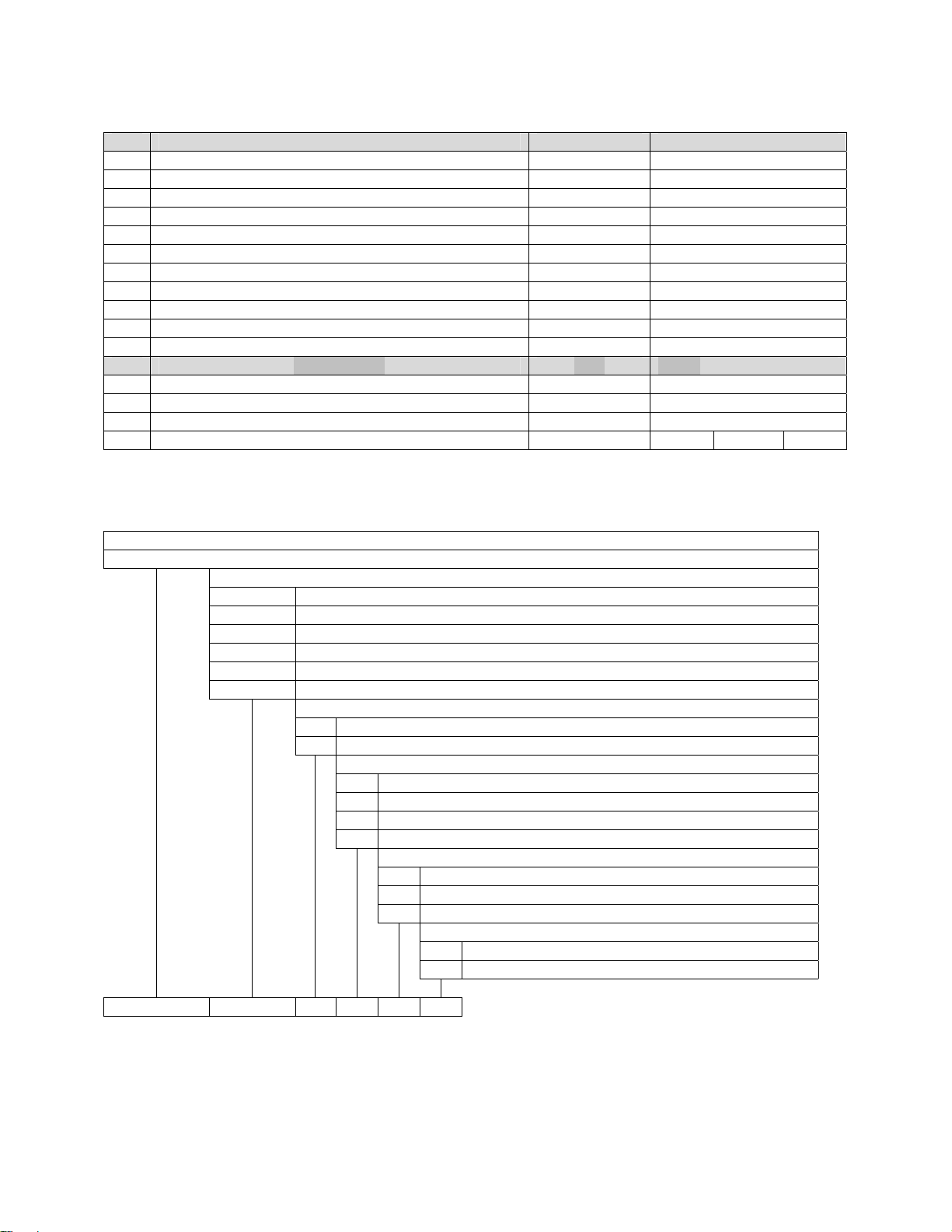
6.0 DIMENSIONS
-
-
-
-
Dimensions (in mm):
50 Nm
100 Nm
CF 189 7 Rev. E; Dec. 12, 2011
A B C D E F G H I
160 93 33,5 15g6 96 60 61 40 57
160 93 33,5 15g6 96 60 61 40 57
Page 8
250 Nm
500 Nm
1000 Nm
2000 Nm
220 93 63,5 25g6 106 70 61 40 67
220 93 63,5 25g6 106 70 61 40 67
350 130 110 40g6 126 90 80 60 87
350 130 110 40g6 126 90 80 60 87
Ball bearing
Load rating
[kN]
Dyn. C Stat.
C
0
Shaft
ending
Ø 15 mm
Ø 25 mm
Ø 40 mm
Distance
K [mm]
Description
Outer
diameter
[mm]
Inner
diameter
[mm]
Max. rotation
of bearing
[rpm]
82.0 E2.6202-2Z/C3 35 15 25,000 7.8 3.75
83.4 61905-2Z 42 25 18,000 7.02 4.3
114.6 6008-2Z 68 40 11,000 17.8 11.6
Dimensions of key stone groove (mm) Key stone DIN 6885 Key stone-position
Shaft
Width Depth Length Height Length Number Distance L
ending
Ø 15 mm
Ø 25 mm
Ø 40 mm
5N9 3 25,5 5 25 1 130,5
8N9 4 50,5 7 50 2 165,5
12N9 5 90,5 8 90 2 252,0
It is recommended to tolerate the hub diameter with H7-clearance. In the situation of dynamic
loads the shaft should be supported with a friction grip, a form lock or a coupling.
CF 189 8 Rev. E; Dec. 12, 2011
Page 9

7.0 CONNECTION PLAN
Pin assignment at Sensor.
Presentation: Top view
Connection example
Model Binder Series 423/723/425
Item number: 09-0132-90-12
Color code according to DIN 47100
Pin Color Description Value
A White Supply voltage
V
CC
B Brown Ground GND
C Green Analog Out 0V…10V
D Yellow Analog GND
E Grey PWM / Frequency /
4-20mA
F Pink Angle Ch A / 0V…5V
G Blue Angle Ch I 0V…5V
H Red Angle Ch B 0V…5V
I Black -
K Violet For internal use only Do not connect
L Grey-Pink For internal use only Do not connect
M Red-Blue Digital GND
11V…28V
8.0 OPERA TING INSTRUCTIONS
8.1 Field of Application
The torque sensor is intended for the use in industrial applications. (e.g. test bench).
8.2 Scope of Delivery
The torque sensor set consists of the sensor itself (signal pick-up and signal processing integrated into
sensor housing), one connecting cable with a soldered plug, key stones and the instruction manual.
CF 189 9 Rev. E; Dec. 12, 2011
Page 10

8.3 Installation and Removal
Make sure to install the sensor shafts exactly with the proper aligned connecting shafts. The key stone
adapter / square endings of the connecting shafts are to be attached forceless to the corresponding ones
of the sensor. The sensor is not designed as a step bearing. No external axial or radial force should be on
the housing of the sensor by fixing it. In case that the bending or radial forces could not avoided the ball
bearing of the sensor must be double-checked. The allowed bearing forces are listed in (Chapter 6.
Dimensions). The M4-screw threads on the side are only for fixing the sensor housing and keeping it from
distortion. A maximum cable length of 3m must not be exceeded. Using a cable or connector other than
supplied by NCTE, or a similar cable that is of a different length may affect the overall performance of the
sensor.
DO NOT REMOVE THE SHAFT WITH TORQUE APPLIED TO THE SENSOR.
8.4 Offset Adjustment
If required the zero point output signal (5V) can be adjusted by pressing the Tare-button. By factory
default the sensor is set to 5V at Null torque.
8.5 Interface Description
Mechanical connection:
The key stone adapters on both ends of the measurement shaft are intended for torque transmission.
Electrical connector:
On the sensor housing there is a 12-pin socket for the power supply and the signal output.(see Chapter 7.
Connection Plan).
8.6 Operation (in regular case or in optimal case)
Optimal measurement parameters may be achieved when the sensor is applied in accordance to the
specification. Use the sensor only for short periods of time at the maximum rotational speed. By
compliance with the specification the sensor works generally trouble-free and maintenance-free.
8.7 Irregular Operation, Measures against Disturbance
The presence of external electromagnetic or magnetic fields can lead to irregular measurement results.
The mechanical overload on the sensor (e.g. exceeding of maximum allowed torque or severe vibrations)
may cause damage to the sensor and in consequence the incorrect signal output. In such cases the
sensor must be reset (see Point 8.4 Offset Adjustment). If this does not help, do not open the sensor but
contact Cooper Instruments directly for assistance.
8.8 Commissioning
After sensor installation pay attention to the followings:
• Switch on the power supply unit and check the supply voltage. Peak voltage to the sensor must
be avoided! Be sure to verify the power supply voltage before connecting the sensor!
• Connect the sensor to the power supply unit by using the delivered cable.
• Connect the sensor output to a high-resistance device such as an A/D converter, oscilloscope,
PC measurement board. The sensor should be in mechanical unloaded state while connecting it.
CF 189 10 Rev. E; Dec. 12, 2011
Page 11

Tare function and error indication:
The LXT 980/981 contains a LED button on the housing surface. Pressing the button will set the signal
output to 5V. The illumination of the button serves as a function / malfunction indicator.
Functional indicator:
LED off: Missing power supply or sensor is damaged.
LED on: Sensor is ready.
Error indicator:
LED flashes: The sensor is not ready.
Flashing of LED can have several possible causes. Various causes are interpreted through a flash code.
After each flash code the LED makes a short pause before repeating the code.
2x flashing: Magnet field sensors defective.
4x flashing: Electronics defective.
8.9 Service / Maintenance
Service-contact:
Tel.: 800-344-3921
Fax: 540-347-4755
8.10 Disposal
For purposes of disposal please send the device back to Cooper Instruments.
8.11 Handling and Transport
While handling, storing and transporting keep sensor away from magnetic and electromagnetic fields
which may exceed the allowed maximum range of EMC listed in Section 3.0, “Technical Characteristics of
the Sensor.”
8.12 Precautions
• Do not open the sensor under any circumstances.
• Do not remove or loosen the locking rings on the shaft ends.
• The mounting nut of the socket as well as the fixing screws should not be loosened or tightened.
• Use only a separate power supply for the sensor
• Use the sensor only according to the specification (Section 3.0 - Technical Characteristics of the
Sensor).
• Keep the sensor away from magnetic and electromagnetic fields which may exceed the allowed
maximum range of EMC (Section 3.0 - Technical Characteristics of the Sensor)
• The sensor is not designed as a step bearing. The existing fixing possibilities serve exclusively for
preventing the sensor from distortion.
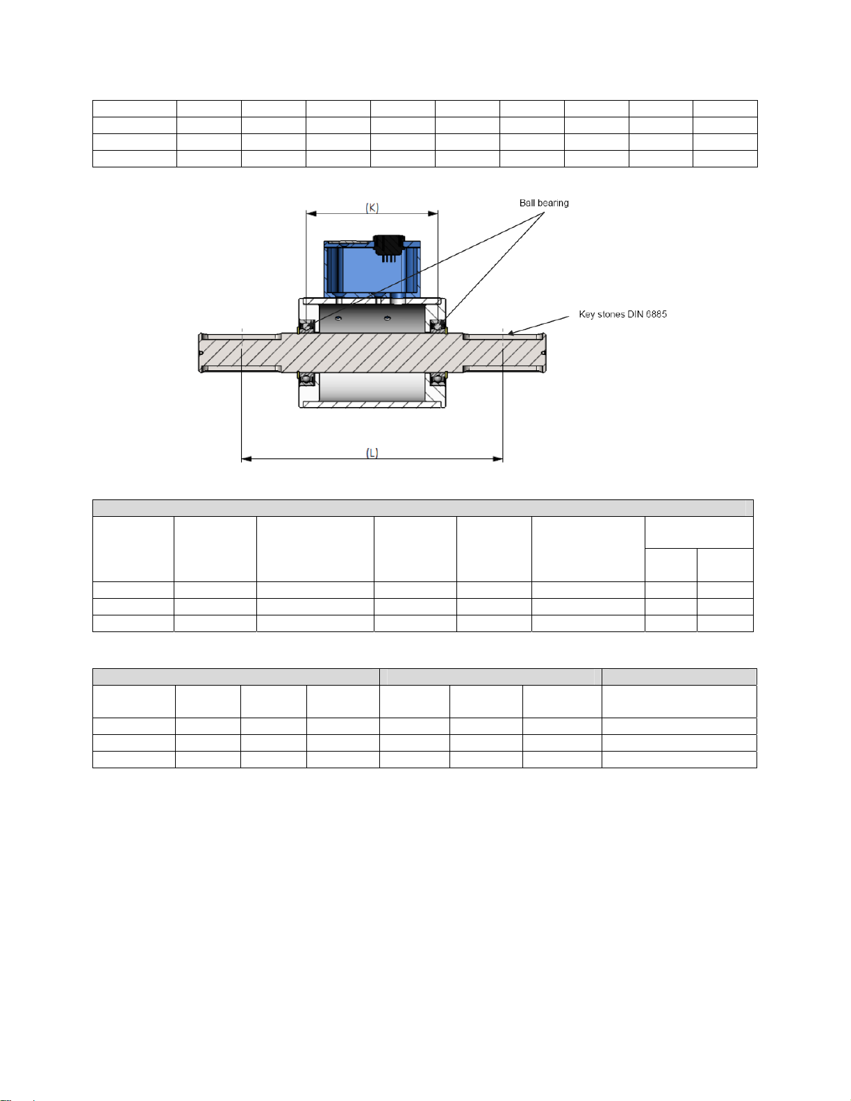
9.0 CALIBRATION AND ACCURACY CLASS
The exact data about the sensor is given in the enclosed factory calibration certificate. Except the sensor
type this certificate also contains the exact calibration data. Each sensor has its own calibration value
CF 189 11 Rev. E; Dec. 12, 2011
Page 12
which is listed in the calibration certificate as well as on the label of the sensor. The calibration certificate
also shows the accuracy of each sensor. The accuracy class of a Cooper Instruments torque sensor
means that the largest single deviation of all values represented in percentage is either smaller than or
equal to the value listed in the accuracy class.
Calibration value:
The calibration characteristic value shows how
much the output signal changes per torque.
There is no difference whether the torque is
directed to the left or to the right.
Hysteresis:
Hysteresis expresses the biggest difference
between upwards and downwards branches at
one torque level in percentage.
Rotational Signal Uniformity (RSU):
RSU is a signal variation created during 360°
rotation of the sensor shaft without torque. The
modulation is the difference between minimal
and maximal values during this single rotation.
RSU is generated by small homogeneities in
the magnetic field and depends mostly on the
property of the sensor shaft.
CF 189 12 Rev. E; Dec. 12, 2011
Page 13

10.0 WARRANTY REPAIR POLICY
Limited Warranty on Products
Any Cooper Instruments product which, under normal operating conditions, proves defective in material
or in workmanship within one year of the date of shipment by Cooper will be repaired or replaced free of
charge provided that a return material authorization is obtained from Cooper and the defective product is
sent, transportation charges prepaid, with notice of the defect, and it is established that the product has
been properly installed, maintained, and operated within the limits of rated and normal usage.
Replacement or repaired product will be shipped F.O.B. from our plant. The terms of this warranty do not
extend to any product or part thereof which, under normal usage, has an inherently shorter useful life than
one year. The replacement warranty detailed here is the buyer’s exclusive remedy, and will satisfy all
obligations of Cooper whether based on contract, negligence, or otherwise. Cooper is not responsible for
any incidental or consequential loss or damage which might result from a failure of any and all other
warranties, express or implied, including implied warranty of merchantability or fitness for particular
purpose. Any unauthorized disassembly or attempt to repair voids this warranty.
Obtaining Service under Warranty
Advance authorization is required prior to the return to Cooper Instruments. Before returning the item,
contact the Repair Department c/o Cooper Instruments at (540) 349-4746 for a Return Material
Authorization number. Shipment to Cooper shall be at buyer’s expense and repaired or replacement
items will be shipped F.O.B. from our plant in Warrenton, Virginia. Non-verified problems or defects may
be subject to a $150 evaluation charge. Please return the original calibration data with the unit.
Repair Warranty
All repairs of Cooper products are warranted for a period of 90 days from date of shipment. This warranty
applies only to those items that were found defective and repaired; it does not apply to products in which
no defect was found and returned as is or merely recalibrated. It may be possible for out-of-warranty
products to be returned to the exact original specifications or dimensions.
* Technical description of the defect: In order to properly repair a product, it is absolutely necessary for
Cooper to receive information specifying the reason the product is being returned. Specific test data,
written observations on the failure and the specific corrective action you require are needed.
CF 189 13 Rev. E; Dec. 12, 2011
 Loading...