

Page 1
STEP 1
T
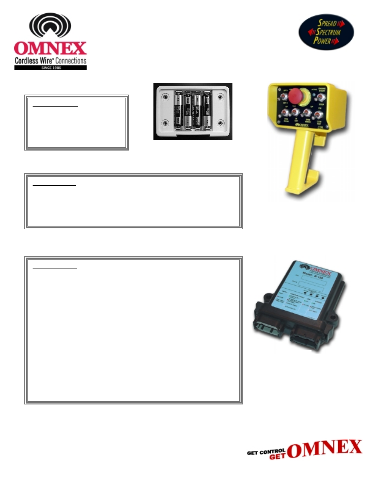
Install Batteries
Remove the battery cover on the
back of the
four AA alkaline batteries as
shown in Figure 1.
, and install the
T150
STEP 2
Power Up T150
T150 / R150 User Guide
Figure 1
Activation of any switch will cause the
safety feature, the
already pressed, released within 10 seconds for unit to remain powered
up.
[EStop]
switch must be pressed and released, or if
to power up. However as a
T150
STEP 3
Using The T150
The
ACTIVE
is transmitting to the
LED will flash brightly upon activation of the switch and return to flashing at
a rate of two times per second when there is no switch activity.
During normal operation the
battery condition.
The
[EStop]
safe way of powering down the
Each switch has a device specific label to identify its function.
LED will flash two times per second indicating that the
. When a function switch is used, the
R150
LOW BATT.
button is used for both an emergency shutdown as well as a
T150
LED will flash to indicate a low
after operation.
T150
ACTIVE
T150
R150
The Trigger is a Proportional Control switch used in conjunction with a
function switch (i.e.
dependent on the option of the receiver but will generally be either a
Voltage, PWM or Current Control.
his device complies with the requirements of the Federal Communication Commissio n (FCC) as specified in document CFR47 Part 15.247 and Industry and
Science Canada (ISC), as specified in document RSS 210. The device is permitted only on a no-interference, no-protection basis, that is, it must cease operation
when it is determined that it causes harmful interference to the services authorized by the FCC or the ISC.
Changes or modifications to the equipment not expressly approved by OMNEX will void the warranty.
DMAN-2293-01
[ROT CW]
Bldg. 74 – 1833 Coast Meridian Road, Port Coquitlam, BC, Canada V3C 6G5
). The type of Proportional Control output is
Rev. 1.03
Page 2

Setting ID Codes
Required when replacing either the Transmitter or Receiver
The Transmitter has its
programmed into it. To do this, the Receiver needs to have its cover removed – refer to Figure 2. Follow the
procedure below to program the Receiver
1. Release the
2. Turn the
3. While holding the
“Download Password” mode.
4. Release the
5. Toggle the switches in sequence:
password code (3142), followed by toggling the
LED’s will flash twice per second. This confirms the unit is in the “Ready to Download” state.
BATT.
6. Press and hold the
per second while depressed and then begin flashing rapidly indicating that the
“Configuration Data” from the
flashing rapidly.
7. Momentarily toggle the
the
R150.
8. Press the
ID Code
[EStop]
on by toggling the
T150
[SW5]
Release
[EStop]
factory programmed. Its matching receiver needs to have this same code
ID Code
switch on the
switch in the UP position, press and release the
[SW5]
switch. The
[SETUP]
[SW5]
and release the
[SW5]
switch to power down the
T150
[SW5]
ACTIVE
[SW3], [SW1], [SW4]
button on the
T150.
switch to the UP position; this enables the
to match its corresponding Transmitter.
.
switch to the UP position.
LED will flash once per second.
and then
switch to the UP position. Both the
[SW5]
for 5 seconds. The
R150
Continue holding the
[SETUP]
T150
button.
, and restart the
[SETUP]
[SW2]
STATUS
button after the
T150
[EStop]
to the UP position to enter the
T150
– refer to
switch. This enables the
LED on the
is ready to receive
R150
STATUS
to send “Configuration Data” to
STEP 2.
ACTIVE
will flash once
R150
LED begins
and
LOW
Current Control Module Calibration
Permits the user to adjust minimum and maximum currents
1. Release the
2. Turn the
3. While holding the
“Download Password” mode.
4. Release the
5. Toggle the switches in sequence:
password code (3144), followed by toggling the
LED’s will flash alternately once per second. This confirms the
6. Select and hold one of the “Proportional Functions” (i.e.
7. With the trigger
[SW5]
8. With the trigger ON (fully engaged), the “MAX” level is set. The “MAX” level may be increased by toggling the
[SW5]
[EStop]
T150 ON
[SW5]
switch up or decreased by toggling the
switch up or decreased by toggling the
on the
by toggling the
switch in the UP position, press and release the
[SW5]
switch. The
(fully released), the “MIN” level is set. The “MIN” level may be increased by toggling the
OFF
.
T150
switch to the UP position.
[SW5]
ACTIVE
LED will flash once per second.
[SW3], [SW1], [SW4]
[SW5]
[SW5]
[SW5]
[EStop]
and then
switch to the UP position. The
[SW4] or [ROT CW]
switch down.
switch down.
[SW4]
T150
to the
is sending “Calibration Data” to the
switch. This enables the
DOWN
).
position to enter the
ACTIVE
and
LOW BATT.
R150
.
9. To reset the “MIN” and “MAX” settings to the factory default, hold the
position for 5 seconds.
10. To exit, press the
[EStop]
switch.
switch in either the UP or
[SW5]
DOWN
Page 3

Transmitter / Receiver Replacement and Service
Fuse
Stat us LED’s
In order to program the
remove the circuit board from the housing of the
or replace the fuse, you will first need to
R150
. This is done by
R150
releasing the two side tabs on the housing, and sliding the connector block
and circuit board out of the housing until the four
visible and the
Also refer to
Codes
Setting ID Codes
to match on both the Transmitter and the Receiver.
[SETUP]
SW1 button is accessible. See Figure 2.
for a step by step procedure of setting
SW 5
STATUS
LED’s are
ID
EStop
[SETUP] SW1
Figure 2
SW 6
SW 1 SW 2 SW 3 SW 4
T150 / R150 Swi tch Func ti on Ta ble
Sw itch Number Position Output Control Pin Assignment Color Code Function
SW1
SW2
SW3
SW4
SW5
SW6
Trigger
Power
Ground
UP Output 9 B3 Green
DOWN Output 10 B4 Green (Blac k / Whi t e)
UP Output 7 B1 White (Red/Black)
DOWN Output 8 B2 Red (Black/White)
UP Output 5 A10 Orange (Blac k )
DOWN Output 6 A12 Orange (Red)
UP Output 3 A9 White (Red)
DOWN Output 4 A11 Blue (Red)
UP Output 11 B5 White
DOWN Output 12 B6 Orange
UP Output 1 A7 Orange (Green)
DOW N Out put 2 A 8 Red (Green)
Released
Engaged
A4 Green (Blac k )Output 13
A6
A3
Red
Black
Proportional Control
9 to 30VDC
Ground
EStop
Driver Power
EStop Output A5
Driver Power Input A2
Jumpered Ex t ernall y
]--
Page 4

Troubleshooting
Inputs and Outputs
The
has 4 LED’s that are used to indicate device status:
R150
ESTOP LED
GREEN – indicates RUN
RED – indicates ESTOP
Flashing RED – indicates fuse blown or relay fault
FUNCTION/FAULT LED
GREEN – indicates function ON, no fault
RED – indicates no voltage to relay, short to ground or blown
fuse
Flashing RED – indicates short to supply or shorted output relay
Not lit – indicates no function
LINK LED
GREEN – indicates Link
RED – indicates No Link
STATUS LED
GREEN – indicates STATUS OK
RED – indicates unrecoverable fault; requires factory authorized
service
Flashing RED – indicates low battery
The
has 2 LED’s that display the mode and status of the device
T150
ACTIVE LED
Momentarily ON or Flashing indicates Power Up procedure or
Programming status. LED will flash with each function during
normal operation indicating Transmit Status to the R150 is good
LOW BATT. LED
Momentarily ON or Flashing indicates Power Up procedure or
Programming status
During normal operation, this LED will only flash to indicate
battery low
ACTIVE and LOW BATT. LED’s
Both LED’s flashing in sync indicates one of the switches is stuck
!!!!!!!
!!!!!!!
!!!!!!!
!!!!!!!
""""
!!!!
!!!!
!!!!
""""
""""
!!!!
!!!!
!!!!
Inputs
4 x 0-5VDC analog inputs (factory
configurable only)
Outputs
Option 1
13 x Form A relay, monitored, 3A max.
each, total combined current 10A
Option 2
12 x Form A relay, monitored, 3A max.
each, total combined current 10A max.
NOTE:
1 x
The Current Control Module may be
Proportional Control
installed as an option giving the user Proportional
Control on output 13 of the
Control Module Calibration
- refer to
R150
for Proportional
Current
Calibration procedures.
The Proportional Control option is available from
the factory in either Voltage Control, PWM or
Current Control.
Replaceable Parts
MINI® Fuse Type,10A LittelFuse
Fuse
Mating Plugs
Pins
Sealing Plug
Wedge
Switches
EStop Switch
EStop Contact Block
Batteries
OMNEX (p/n F0047) or equiv.
OMNEX (p/n’s J0418 / J0419)
OMNEX (p/n J0417)
OMNEX (p/n J0421)
OMNEX (p/n J0420)
OMNEX (p/n S0042)
OMNEX (p/n S0072)
OMNEX (p/n S0071)
OMNEX (p/n B0010) 4 x AA
I/O Diagram Deutsch Connector Pin Assignments
4.92”
R150 Internal
EStop
Internal Power
13
1
Dimensions
7.87”
A4
B6
B5
B4
B3
B2
B1
A12
A10
A11
A9
A8
A7
Internally Fused
A2
A5
A6
A3
4.13”
R150 Relay Outputs
R150
The
shown using a 10A MINI® fuse.
Follow the steps in Transmitter /
Receiver replacement to open
the
Driver Power Input
Jumpered on wiring harness
EStop Out
Power
Ground
is internally fused as
R150
for fuse replacement.
R150
5.13”
Connector A (Grey)
Output 6
Output 4
Output 5
Output 3
Output 2
Output 1
12
11
10
9
8
7
OMNEX Control Systems Inc. Warrants to the original purchaser that the OMNEX
products are free from defects in materials and workmanship under normal use and
service for a period of ONE YEAR, parts (EXCLUDING: SWITCHES, CRYSTALS, OR
PARTS SUBJECT TO UNAUTHORIZED REPAIR OR MODIFICATION) and labor
from the date of delivery as evidenced by a copy of the receipt. OMNEX’s entire
liability and your exclusive remedy shall be, at OMNEX’s option, either the (a) repair
or (b) replacement of the OMNEX product which is returned within the warranty period
to OMNEX freight
purchase receipt and with the return authorization of OMNEX. If failure has resulted
from accident, abuse or misapplication, OMNEX shall have no responsibility to repair
or replace the product under warranty. In no event shall OMNEX be responsible for
incidental or consequential damage caused by defects in its products, whether such
damage occurs or is discovered before or after replacement or repair and whether or
not such damage is caused by the negligence of OMNEX Control Systems Inc.
Neither OMNEX nor its Distributors shall be liable for any delay or failure of the
performance of any of its obligations under this agreement caused by acts of God,
labor disputes, embargoes, boycotts, shortage of parts or any cause beyond its
reasonable control.
Neither OMNEX nor its Distributors shall be responsible for incurred costs associated
with border clearance or with the delay of the OMNEX products in transit to OMNEX.
Any charges associated with the return of the OMNEX products may be subject
to billing to the original purchaser in the event that the OMNEX products are
NOT covered by the warranty as noted above.
1
Input 1
2
Driver Power
GND
3
4
Output 13
EStop Output
5
Power
6
WARRANTY
by the OMNEX APPROVED carrier with a copy of the
collect
Output 12
Output 11
Output 10
Output 9
Output 8
Connector B (Black)
6
5
4
3
2
1Output 7
7
8
9
10
11
12
Factory Configurable Only
RS485 B
RS485 A
RS485 EN
Input 4
Input 3
Input 2
AB
4.00”
Bldg. 74 – 1833 Coast Meridian Road, Port Coquitlam, BC, Canada V3C 6G5
 Loading...