

Page 1

Kyle® Form 4C Recloser Control
Front Panel Replacement Kit KME4-701
Installation Instructions
Reclosers
Service Information
Contents
S280-77-13
Printed in USA
1
February 2002 • New Issue (Supersedes KB083 3/01)
Safety Information . . . . . . . . . . . . . . . . . . . . . . . . . 2
Safety Instructions . . . . . . . . . . . . . . . . . . . . . . . . 2
Hazard Statement Definitions . . . . . . . . . . . . . . . . 2
Product Information . . . . . . . . . . . . . . . . . . . . . . . . 3
Introduction . . . . . . . . . . . . . . . . . . . . . . . . . . . . . 3
Description . . . . . . . . . . . . . . . . . . . . . . . . . . . . . 3
Installation . . . . . . . . . . . . . . . . . . . . . . . . . . . . . . . 4
Application of New Control Labels . . . . . . . . . . . . 4
Removal of Front Panel Assembly . . . . . . . . . . . . 5
Installation of Control Panel . . . . . . . . . . . . . . . . . 6
Programming and Testing . . . . . . . . . . . . . . . . . . 7
Troubleshooting . . . . . . . . . . . . . . . . . . . . . . . . . . 7
Figure 1.
Kyle®Type Form 4C Recloser Control
961066KM
Page 2

Kyle®Type Form 4C Recloser Control Front Panel Replacement Kit KME4-701
2
The instructions in this manual are not intended as a substitute for proper training or adequate experience in the
safe operation of the equipment described. Only competent technicians who are familiar with this equipment
should install, operate, and service it.
A competent technician has these qualifications:
• Is thoroughly familiar with these instructions.
• Is trained in industry-accepted high- and low-voltage
safe operating practices and procedures.
• Is trained and authorized to energize, de-energize,
clear, and ground power distribution equipment.
• Is trained in the care and use of protective equipment
such as flash clothing, safety glasses, face shield,
hard hat, rubber gloves, hotstick, etc.
Following is important safety information. For safe installation and operation of this equipment, be sure to read
and understand all cautions and warnings.
Safety Instructions
Following are general caution and warning statements
that apply to this equipment. Additional statements, related to specific tasks and procedures, are located throughout the manual.
SAFETY INFORMATION
WARNING: This equipment is not intended to
protect human life. Follow all locally approved procedures and safety practices when installing or operating this equipment. Failure to comply can result in
death, severe personal injury, and equipment damage.
G102.1
DANGER: Hazardous voltage. Contact with
hazardous voltage will cause death or severe
personal injury. Follow all locally approved safety procedures when working around high and low voltage
lines and equipment. G103.3
WARNING: Before installing, operating, main-
taining, or testing this equipment, carefully read
and understand the contents of this manual. Improper
operation, handling or maintenance can result in death,
severe personal injury, and equipment damage. G101.0
WARNING: Power distribution equipment must
be selected for the intended application. It must
be installed and serviced by competent personnel who
have been trained and understand proper safety procedures. These instructions are written for such personnel
and are not a substitute for adequate training and experience in safety procedures. Failure to properly select,
install, or maintain this equipment can result in death,
severe personal injury, and equipment damage. G122.2
SAFETY FOR LIFE
Cooper Power Systems products meet or exceed all applicable industry standards relating to product safety. We actively
promote safe practices in the use and maintenance of our products through our service literature, instructional training
programs, and the continuous efforts of all Cooper Power Systems employees involved in product design, manufacture,
marketing, and service.
We strongly urge that you always follow all locally approved safety procedures and safety instructions when working
around high voltage lines and equipment and support our “Safety For Life” mission.
This manual may contain four types of hazard
statements:
DANGER: Indicates an imminently hazardous situation which, if not avoided, will
result in death or serious injury.
WARNING: Indicates a potentially hazardous
situation which, if not avoided, could result in
death or serious injury.
CAUTION: Indicates a potentially hazardous
situation which, if not avoided, may result in
minor or moderate injury.
CAUTION: Indicates a potentially hazardous situation which, if not avoided, may result in equipment damage only.
Hazard Statement Definitions
!
SAFETY
FOR LIFE
!
SAFETY
FOR LIFE
!
!
!
!
!
!
!
Page 3

Introduction
Service Information S280-77-13 provides instructions for
replacing the front panel of the Form 4C Recloser
Control. Before installing this kit, carefully read and
understand the contents of this manual.
Description
The kit includes the parts necessary to replace the front
panel of the Form 4C control.
Review ALL steps in this publication before installing the
enclosed kit. In addition, refer to the included Form 4C
Service Information S280-77-1 before the control is placed
back into service. Service Information S280-77-1 provides
control operation, maintenance instructions and testing
procedures for Form 4C Microprocessor-Based Recloser
Control.
The parts included in the Form 4C Front Panel Kit are listed in Table 1.
For installation of the kit, the following tools are required.
• Kyle Type METElectronic Recloser T ester or equivalent.
•5/16” wrench
•11/32” wrench
•A standard screwdriver
Note: Routing of the panel harness may differ from the origi-
nal routing.
Note: The view may differ slightly for different revisions of
Form 4C controls.
S280-77-13
3
!
PRODUCT INFORMATION
TABLE 1
Kit KME4-701 Parts
Qty. Catalog Number Description
1 S280-77-13 Kit Installation Instructions
1 S280-77-1 Form 4C Installation/Operation Manual
1 S280-77-4 Form 4C Programming Guide
1 KME40003000001 Form 4C Control Panel Assembly
1 KME4000203 Connector Cable Assembly (Option I/O)
1 KA20720001 18” length of Plastic Spiral Cable Wrap
3 KA20060020 Plastic Cable Clamps
4 KA20200028 Elastic Stop Nut
1 KME4-1235 Accessory Label (See Figure 3)
1 KME4-1110 Cabinet Door Revision Label (See Figure 3)
1 KME4-1133 Optional I/O Label (See Figure 3)
5 KA23580007 Ty-Wraps
4 KA23580008 Ty-Wraps
1 KME4-1214 Malfunction Code Label (See Figure 3)
1 KA20060001 Cable Clip
1 KA20060008 Cable Clip
1 KA20200005 Elastic Stop Nut
Figure 2.
Identification of various part locations on Form 4C controls.
SAFETY
FOR LIFE
Communications Accessory
Plastic Cable Clamp
Connector Cable Assembly
(Optional I/O)
Groundwire and #8
P4
Nut and Lockwasher
Plastic Spiral
Cable Wrap
Elastic Stop Nuts
Trip Test
Accessory
Tie Wraps
Form 4C Control
Panel Assembly
KME4-148
Fiber-Optic Digital
P2
P6
P7
Door-Stop Link
P15
Battery Connector
P19
Control Cable
Receptacle
P12
P8
Page 4

Application of New Control
Labels
To reflect the new features available in the Form 4C
Control, new labels must be added to the unit’s inside
door panel.
1. Remove the document spring clip on the inside of the
control door panel. Retain spring clip for re-installation at the end of this procedure.
2. Clean the inside of the door panel with isopropanol
alcohol to remove excess dirt and contaminants from
the original accessory label surface.
3. Apply the new accessory label KME4-1235 to the
inside door panel as shown in Figure 3.
4. Apply the malfunction code label KME4-1214 to the
inside door panel as shown in Figure 3.
5.If the control is equipped with the optional I/O accessory , place label KME4-1133 as shown in Figure 3. (If
optional I/O accessory is not installed, discard label
KME4-1133).
6. Re-install the spring clip on the inside door panel.
7. Clean the area directly below the nameplate on the
front door of the control cabinet.
8. Apply the kit label KME4-1110 directly below the
nameplate on the cabinet front door panel.
Kyle
®
Type Form 4C Recloser Control Front Panel Replacement Kit KME4-701
INSTALLATION
4
Figure 3.
Application of labels inside of door panel (left), label application outside door panel (right).
KME4-1133
Optional I/O Board
Label
KME4-1235
Accessory Label
Document Spring Clip
Form 4C Recloser Control Cabinet Door
KME4-1214
Malfunction
Code Label
KME4-1110 Cabinet Door Revision Label
Kyle Type Form 4C
Page 5

Removal of Front Panel
Assembly
Refer to Figure 3 for part locations. The view may differ
slightly for different versions of the Form 4C control.
Proceed as follows:
1. Remove the control from service. Follow all locally
approved safety regulations, practices, and procedures. Refer to S280-77-1 Kyle Form 4C
Microprocessor-Based Recloser Control Installation
and Operation Instructions prior to removal of panel.
A. Set Ground Trip Block switch to BLOCK.
B. Disconnect control cable from the control.
C. De-energize/disconnect ac power from the control.
D. Unplug the control battery.
2. Disconnect the battery connector.
3. Disconnect the front panel ground strap by removing
the grounding nut on the back panel. Discard ground
strap.
4. Disconnect cable plug from the standard I/O Board
socket P7. Release the cable from the ty-wraps and
cable clamps.
Note: Newer Form 4C controls also use cable clamps.
5. Disconnect the cable plug from power supply plug
P12. Release the cable back panel cable clamps.
6. If the control is equipped with an optional I/O board,
disconnect the cable plug from socket P15 on the
optional I/O board. Release the cable from the tywraps and cable clamps if present.
7. Remove and retain the cable clamp hardware from
the top right corner of the front panel assembly.
Disconnect the cable plug from socket P2.
8. Disconnect the panel door-stop link by removing the
spring clip and hinge pin. Retain for later use.
9. Remove the existing control panel by lifting the panel
off it’s slide hinges.
S280-77-13
5
!
CAUTION: Recloser misoperation. The control
must be removed from service before disconnecting the control battery. Disconnecting the control
battery from an in-service control may cause recloser
misoperation (unintentional operation). Failure to comply can result in equipment damage and personal
injury. T213.4
CAUTION: Equipment damage. Always wear a
grounding wrist strap to control static electricity before
handling circuit boards. Failure to use this strap may
result in circuit board damage. T253.1
CAUTION: Control damage. De-energize both
ac and dc power prior to removing or installing
any internal connections or circuit boards in the control. Failure to comply can result in damage to the control. T241.1
IMPORTANT: Electro-static discharge. All microprocessor equipment is subject to electrostatic discharge (ESD) damage which can affect programming
or result in component degradation or failure.
To prevent possible ESD damage to circuit boards,
make sure of the following when removing, handling,
or installing circuit boards:
• Make sure the control is grounded.
• Use a grounding wrist strap connected to the con-
trol ground connection.
• Always transport and store circuit boards in staticfree packaging.
SAFETY
FOR LIFE
!
!
Page 6

Installation of Form 4C Control
Panel
Refer to Figure 4 for part locations. The view may differ
slightly for different versions of the Form 4C control.
1. Install the new Form 4C Control panel by sliding it
onto the control cabinet hinge pins and reconnecting
the door link.
2. Reconnect the cable plug to board socket P2 using
the cable clamp hardware that was removed during
the disassembly process.
3. Connect the cable plug to socket P12 on the power
supply board. Use the cable clamps on the back
panel to secure the cable.
4. Connect the cable plug to socket P7 on the standard
I/O board.
5. If the control is equipped with a optional I/O board,
connect the kit cable KME4-203 to the optional I/O
board socket P15 and the CPU board socket P4.
Note: If the control does not have the optional I/O board,
discard KME4-203 cable assembly.
6. Use the ty-wraps and spiral wrap to bundle the panel
control cable and optional I/O cable KME4-203 (if
installed).
7. Use cable clamp hardware included with the kit to
secure the cable assembly to the front control panel
(Figure 4).
8. Make sure the panel ground wire is routed under the
cable and secured to the back plate.
9. Use the cable clamps and ty-wraps inside the cabinet
to secure the panel cables to the control cabinet wall.
10. Visually inspect the control cabinet for damaged or
unconnected cables or wires. Make sure cable routings are as shown in Figure 4 and Figure 5 before
proceeding.
11. If desired, install the the Trip Test Accessory.
Instructions are included with the accessory.
12. Program and test the installed kit. Refer to
Programming and Testing the Installed Kit section
of this manual.
Kyle®Type Form 4C Recloser Control Front Panel Replacement Kit KME4-701
6
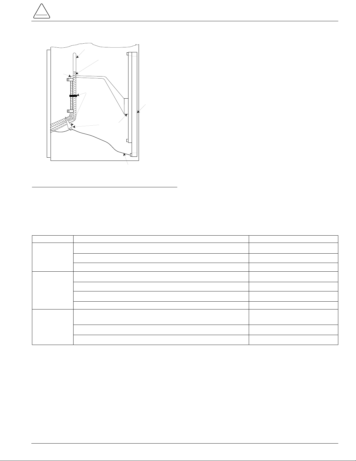
Figure 4.
Correct panel ground strap routing.
CAUTION: Equipment damage. Always wear a
grounding wrist strap to control static electricity before
handling circuit boards. Failure to use this strap may
result in circuit board damage. T253.1
CAUTION: Control damage. De-energize both
ac and dc power prior to removing or installing
any internal connections or circuit boards in the control. Failure to comply can result in damage to the control. T241.1
!
Connector Cable Assembly
(Optional I/O)
Groundwire and #8
Nut and Lockwasher
Plastic Spiral
Cable Wrap
Trip Test
Accessory
Tie Wraps
Form 4C Control
Panel Assembly
KME4-148
P4
Plastic Cable Clamp
Elastic Stop Nuts
Communications Accessory
Fiber-Optic Digital
P2
P15
P6
P7
Door-Stop Link
Battery Connector
P19
Control Cable
Receptacle
P12
P8
Page 7
Programming and Testing the
Installed Kit
Note: Follow the testing and programming procedures in
S280-77-1 Kyle Form 4C Microprocessor-Based
Recloser Control Installation and Operation Instructions
before placing the control back in service.
1. Reconnect the battery connector.
2. Energize the control with AC power.
3. Program the control. Refer to S280-77-4 Kyle
®
Form
4C Microprocessor-Based Recloser Control
Programming Guide for further information.
4. Test the control with the Kyle®Type MET Electronic
Control Tester (or equivalent) to verify proper programming and operation
5. After all programming and testing has been successfully completed, the control may be reinstalled and
placed into service. Refer to S280-77-1 Kyle Form 4C
Microprocessor-Based Recloser Control Installation
and Operation Instructions.
Troubleshooting
If the front panel fails to operate properly , review the troubleshooting information in Table 2 prior to contacting your
Cooper Power Systems representative.
S280-77-13
7
!
Figure 5.
Securing with Ty-wraps.
Problem Possible Causes Remedy
No power to control. Neon lamp on power supply should be “ON”. Connect power.
Cable to power supply P12 not connected. Connect plug.
Cables incorrectly attached or damaged. Inspect all cables.
Battery left connected without 120 Vac supplied to control. Contact Cooper Power Systems.
Battery drained. Contact Cooper Power Systems.
Battery disconnected. Connect battery.
Cables incorrectly attached or damaged. Inspect all cables.
Incorrect program parameters. Verify unit was programmed
correctly. Refer to S280-77-4*.
Cables incorrectly attached or damaged. Inspect all cables.
Cable socket pins bent. Inspect / straighten pins.
Display Will
Not Turn
On
Malfunction
Display ON
and Check
Battery
Display ON
Unit Failed
KMET
Testing
* S280-77-4 Kyle®Form 4C Microprocessor-Based Recloser Control Programming Guide
TABLE 2
Troubleshooting Information
SAFETY
FOR LIFE
To P15
To P12
Ty-Rap*
Cabinet Side View
Option I/O
KME4-203
Ref
P7
*Tighten to remove
slack in cables
Grounding Wire
Back Plate
Page 8

KA2048-590 Rev: 00
Kyle®Type Form 4C Recloser Control Front Panel Replacement Kit KME4-701
P.O. Box 1640
Waukesha, WI 53187
www.cooperpower.com
©2002 Cooper Power Systems, Inc.
Kyle
®
is a registered trademark of Cooper Industries, Inc.
Printed on Recycled Paper
KYLE
02/02
!
SAFETY
FOR LIFE
 Loading...