

Page 1

T245 Control System
Installation and Operations Manual
DMAN-2053-01
Issue 5
November 27, 2001
2001 OMNEX Control Systems Inc.
All rights reserved.
Page 2

T245 Control System Manual
OMNEX Control Systems, Inc.
#74 – 1833 Coast Meridian Road,
Port Coquitlam, B.C.
Canada V3C 6G5
Telephone: (604) 944-9247
Fax: (604) 944-9267
http://www.omnexcontrols.com
ii
Page 3

T245 Control System Manual
Revision History
Issue Description Pages
04 Revision history added, T247 Hoffman box added to Part Numbers iii, 2
05 Added Throttle Enable O11, changed operation of Hydrosync shift 10, 17
Deleted obsolete part numbers 1
iii
Page 4

T245 Control System Manual
This page is intentionally left blank.
iv
Page 5

T245 Control System Manual
Contents
1. Introduction..........................................................................................................................1
1.1. Part Numbers ...........................................................................................................1
2. Physical Installation .............................................................................................................3
2.1. Receiver/Controller..................................................................................................3
2.2. Receiver Antenna.....................................................................................................3
2.3. Platform Holster Magnet..........................................................................................4
3. Considerations for Electrowelding ......................................................................................5
4. Electrical Connections .........................................................................................................6
5. Fuses, Configuration Jumpers............................................................................................11
5.1. R1300+ Board........................................................................................................11
5.2. S20 Board ..............................................................................................................11
6. Setting Up the Radio Receiver..................................................................................................12
6.1. Unique Identifier (Radio ID)......................................................................................12
6.2. No-Link Data Mode...................................................................................................13
6.3. Checksum Mode ........................................................................................................13
6.4. Changing Switch Settings..........................................................................................13
7. Operations..........................................................................................................................14
7.1. Receiver/Controller................................................................................................14
7.1.1. Error Codes ................................................................................................14
7.2. T245/T45 Radio Transmitter .................................................................................14
7.2.1. Switching The Transmitter ON and OFF...................................................14
7.2.2. Operator Controls: .....................................................................................15
7.2.3. Tilt Failsafe ................................................................................................16
7.2.4. Low Battery Indicator ................................................................................16
7.2.5. Battery Charging and Replacement ...........................................................16
7.2.6. Transmitter Light Summary.......................................................................17
7.2.7. Numeric Display ........................................................................................17
7.3. T247/T47 Cable Remote........................................................................................18
7.4. Emergency Override Panel ....................................................................................19
8. Proportional Drive Adjustments ........................................................................................20
9. Factory Parameters.............................................................................................................25
9.1. Types of Factory Parameters..................................................................................25
9.2. Changing the Factory Parameters ..........................................................................25
9.3. List of Factory Parameters .....................................................................................26
PWM Drive Frequency Parameters .......................................................................29
Boom Load Moment Limit....................................................................................29
Boom Derating Factors..........................................................................................29
Emergency Override Panel Function Speed ..........................................................29
Auger Shake Speed................................................................................................29
v
Page 6

T245 Control System Manual
Digger Transmission Type.....................................................................................29
Bucket/Pole-Claw Speed Ratio..............................................................................29
10. Warranty .................................................................................................................................30
vi
Page 7

T245 Control System Manual
1. Introduction
The T45 Control System consists of a custom Receiver/Controller (grey
box), an optional T245 Radio Transmitter and/or an optional T247 Cable Remote. An
interface is also provided for an optional user-supplied Emergency Override Panel. The
main components of the Receiver/Controller are an R1300+ (TPCB-1225-10) circuit
board, an S20 (TPCB-1458-03) board, and a DEX-900 radio receiver.
The Receiver/Controller’s software is custom-designed for many applications.
Various sensors mounted on the machine chassis send feedback information to the
Receiver/Controller. This feedback information together with the operator commands
determine the drive outputs to the Apitech™ electric-over-hydraulic valves. A
sophisticated computer program, permanently encoded into the firmware chips of the
Receiver/Controller, governs the mapping of inputs to outputs.
Features of the computer program include safety interlocks to prevent injury to
personnel as well as damage to the machine. The program incorporates a “restart” check
which ensures that functions do not actuate unexpectedly due to operator panel switches
being left “on” by accident.
All wiring to the Receiver/Controller is through waterproof circular M.S.
connectors on the outside of the fibreglass enclosure, to ensure that the NEMA 4X rating
of the enclosure is preserved. This manual describes considerations which should be
taken during installation and operation, and gives procedures for “tuning” the system to
match the exact characteristics of your hydraulic valves
.
1.1. Part Numbers
The list below gives the part numbers of the major components of the T245
Control System. You will need these numbers for reference and ordering spare parts.
Component OMNEX Part
Number
R2305 Receiver (supports T245, T47 and
T247; replaces R1302 and R1305)
Factory Key for Receiver/Controller ACAB-1355-02 19444-1
User Key for Receiver/Controller ACAB-1355-01 Y1619
Shock Mount Kit for
Receiver/Controller
ASSY-1992-01 19425-1
AKIT-1498-01 Y1616
Versalift Part
Number
Antenna Kit for Receiver/Controller A0005 19292-1
Output Cable with 54-pin Connector, 6
feet
Emergency Override Panel Interface ACAB-1734-01 —
ACAB-1733-01 —
1
Page 8

T245 Control System Manual
1. Introduction
The T45 Control System consists of a custom Receiver/Controller (grey
box), an optional T245 Radio Transmitter and/or an optional T247 Cable Remote. An
interface is also provided for an optional user-supplied Emergency Override Panel. The
main components of the Receiver/Controller are an R1300+ (TPCB-1225-10) circuit
board, an S20 (TPCB-1458-03) board, and a DEX-900 radio receiver.
The Receiver/Controller’s software is custom-designed for many applications.
Various sensors mounted on the machine chassis send feedback information to the
Receiver/Controller. This feedback information together with the operator commands
determine the drive outputs to the Apitech™ electric-over-hydraulic valves. A
sophisticated computer program, permanently encoded into the firmware chips of the
Receiver/Controller, governs the mapping of inputs to outputs.
Features of the computer program include safety interlocks to prevent injury to
personnel as well as damage to the machine. The program incorporates a “restart” check
which ensures that functions do not actuate unexpectedly due to operator panel switches
being left “on” by accident.
All wiring to the Receiver/Controller is through waterproof circular M.S.
connectors on the outside of the fibreglass enclosure, to ensure that the NEMA 4X rating
of the enclosure is preserved. This manual describes considerations which should be
taken during installation and operation, and gives procedures for “tuning” the system to
match the exact characteristics of your hydraulic valves. CAUTION: Changes or modifications
not expressly approved by the party responsible for compliance could void the user's authority
to operate the equipment.
1.1. Part Numbers
The list below gives the part numbers of the major components of the T245
Control System. You will need these numbers for reference and ordering spare parts.
Component OMNEX Part
Number
R2305 Receiver (supports T245, T47 and
T247; replaces R1302 and R1305)
Factory Key for Receiver/Controller ACAB-1355-02 19444-1
User Key for Receiver/Controller ACAB-1355-01 Y1619
Shock Mount Kit for
Receiver/Controller
ASSY-1992-01 19425-1
AKIT-1498-01 Y1616
Versalift Part
Number
Antenna Kit for Receiver/Controller A0005 19292-1
Output Cable with 54-pin Connector, 6
feet
Emergency Override Panel Interface ACAB-1734-01 —
ACAB-1733-01 —
1
Page 9
T245 Control System Manual
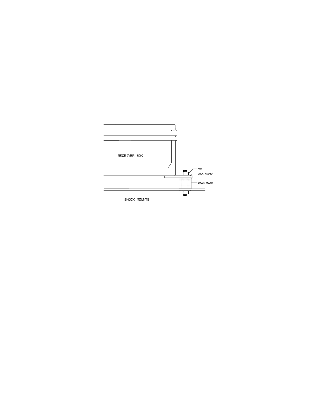
2. Physical Installation
2.1. Receiver/Controller
The Receiver/Controller should be mounted with the connectors down, and in a
location so that the enclosure door may be opened conveniently for access to the inside.
Shock mounts must be used to mount the enclosure!
should the enclosure be directly bolted to the machine. Figure 1 below illustrates how the
shock mounts should be installed:
Figure 1
The Receiver/Controller enclosure is sealed and has a NEMA-4 rating. When
installing, ensure that nothing is done to compromise the watertightness of the enclosure.
When performing maintenance it may be necessary to gain access to the inside of the
enclosure; take care to re-close the door securely when you are done.
Enclosure Mounting
Under no circumstances
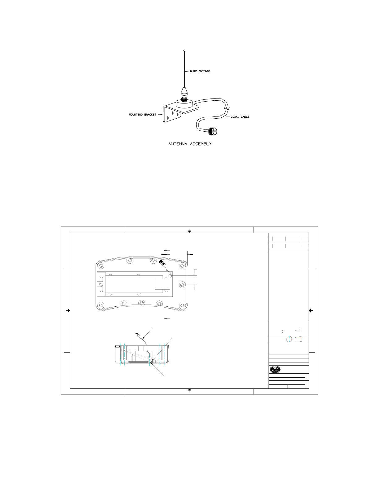
2.2. Receiver Antenna
The receiver antenna should be mounted pointing up and as high as possible,
preferably with a large metal surface below it but no metal above or to the side. The
antenna must be mounted on the outside of the machine; do not mount it inside an
operator’s cab or in a toolbox. Assemble the antenna as shown in Figure 2 below, and
thread (finger-tight only) the connector onto the matching receptacle on the
Receiver/Controller.
3
Page 10
T245 Control System Manual
Figure 2
Antenna Assembly
2.3. Platform Holster Magnet
The magnet which indicates to the T245 Radio Transmitter that it is in the
platform holster should be mounted with the plastic face up, towards the T245. The
drawing below is an internal view of the T245 bottom half, indicating where the magnetic
switch is.
4321
SWITCH , MAGNATIC REED
D
A
2.200
(P/N: SX-MPS9WGN)
INSTALLATION INSTRUCTION.
1.100
C
A
B
A
SECTION A-A
4321
18 AWG 3.75" WHT.
2 PLACES.
SILICONE SEALING
ALL WAY AROUND.
DRILL 3.5 DIA. HOLE ON T45 BOTTOM ONLY,
(PRESS FIT)
NOT DRILL ON BATTERY BOTTOM.
REVISIONS
REV DATE: APPROVED: ECO
1 05-12-99
DESCRIPTION:
T45 Bot. Versalift -Iss1
DATE:REV APPROVED: ECO
DESCRIPTION:
GENERAL NOTES:
1. MATERIAL: SWITCH, MAGNETIC REED
INSTALLATION INSTRUTION.
UNLESS OTHERWISE SPECIFIED
DIMENSIONS ARE IN INCHES
TOLERANCES
DECIMALS ANGULAR
.XX + .05 + 0.5
.XXX + .010
DO NOT SCALE DRAWING
THIRD ANGLE
PROJECTION:
THESE DESIGNS AND SPECIFICATIONS ARE THE
PROPERTY OF OMNEX CONTROL SYSTEMS INC.
AND SHALL NOT BE COPIED OR USED FOR
MANUFACTURING WITHOUT ITS WRITTEN
CONSENT.
CHECKED:
DRAWN:
DESIGNED:
TITLE:
PART #:
DRAWING #:
SCALE:
DATE:
R T F 05-12-99
DATE:
G. C. 05-12-99
DATE:
W. H. 05-12-99
OMNEX
Control Systems Inc.
T45 Bot. Versalift -Iss1
ASUB-1327-03
DSUB-1327-03
SHEET: OF
1 : 2 1 1
D
C
B
REV
A
1
SIZE
B
Figure 3
T245 Magnetic Switch
4
Page 11

T245 Control System Manual
3. Considerations for Electrowelding
The electronics in the T245 Control System can be damaged by the high currents
and voltages employed in electrowelding. If electrowelding must be performed after the
Control System has been installed, observe the following precautions to reduce the risk of
damage:
• Do not connect the ground clip to a point on the chassis close to the
enclosures.
• Disconnect the harnesses to the enclosures and sensors at the M.S. connectors.
Also disconnect the battery (PTO switch) and ground connections going into
the enclosures.
• Do not strike an arc close to the enclosures and sensors, or wiring leading into
the enclosures and sensors.
• Do not weld to the sensors.
5
Page 12

T245 Control System Manual
4. Electrical Connections
The Receiver/Controller has two circular M.S. connectors for connection to your
chassis wiring. A 54-pin M.S. connector is used for power and function outputs. A 16pin M.S. connector is provided for connection to the T47 Cable Remote or Emergency
Override Panel. The following tables specify the assignment of each pin, with
corresponding markings on the circuit boards for reference. The wire numbers refer to
the old-style Output Cable and not the new Custom Output Harness.
Main Connector (Power and Functions):
Function Wire # 54-pin (32A10P)
M.S. Pin
Ground 48,38 A, AF J15 (R1300), J3 (S20)
Power for Electronics (Battery Positive) 39 AG J12 (R1300), J1 (S20)
Power for Function Outputs (Batt. +) yellow
+green
Dump Valve Output (drives power out
when radio signal is being received
from transmitter)
Engine START 24 D D2 (R1300)
Engine STOP 47 E D1 (R1300)
Winch DOWN 29 F 1+ (R1300)
Winch UP 25 G 1- (R1300)
Digger DIG 46 H 2+ (R1300)
Digger CLEAN 45 J 2- (R1300)
Lower Boom LOWER 5 K 3+ (R1300)
49 C J13 (R1300), J2 (S20)
B J14 (R1300)
Board References
Lower Boom RAISE 14 L 3- (R1300)
Intermediate Boom EXTEND 23 M 4+ (R1300)
Intermediate Boom RETRACT 26 N 4- (R1300)
Upper Boom EXTEND 3 O 5+ (R1300)
Upper Boom RETRACT 22 P 5- (R1300)
Pole Guide/Platform LOWER 44 R 6+ (R1300)
Pole Guide/Platform RAISE 30 S 6- (R1300)
Boom Rotate CCW 6 T O1 (S20)
Boom Rotate CW 13 U O2 (S20)
6
Page 13

T245 Control System Manual
Function Wire # 54-pin (32A10P)
M.S. Pin
Pole Guide/Platform OPEN 12 V O3 (S20)
Pole Guide/Platform CLOSE 21 W O4 (S20)
Digger Shift HIGH 27 X O5 (S20)
Digger Shift LOW 4 Y O6 (S20)
Auger LATCH 2 Z D4 (R1300)
Auger UNLATCH 20 a D5 (R1300)
Throttle UP 31 b D6 (R1300)
Throttle DOWN 7 c D7 (R1300)
Emergency Power 9 d D3 (R1300)
Electronic Throttle Output (pulse-width
modulated signal; formerly 0 to 5V)
Hydraulic Tool Valve 43 f D8 (R1300)
Upper Boom Extended Switch (N.O.
contact)
1 e O9 (S20)
32 g J2 pin 6 (R1300)
Board References
Intermediate Boom Retracted Switch
(N.O. contact)
Upper Boom Retracted Switch (N.O.
contact)
(not used) — k —
Auger Overstow Switch (N.O. contact)
Input
(spare switch input) 15 n J2 pin 3 (R1300)
(spare switch input) 17 p J2 pin 4 (R1300)
Boom Stowed Switch (N.O. Contact)
Input
+5V Power for N.O. Switches 42 r J2 pin 1 (R1300)
+5V for Proportional Pressure and
Angle Sensors
Angle Sensor Input
(-20.0° = 0.5V, +80.0° = 4.5V)
28 h J2 pin 7 (R1300)
8 j J2 pin 8 (R1300)
33 m J2 pin 2 (R1300)
11 q J2 pin 5 (R1300)
34 s J3 pin 1 (R1300)
16 t J3 pin 3 (R1300)
7
Page 14

T245 Control System Manual
Function Wire # 54-pin (32A10P)
M.S. Pin
Lift Cylinder Piston-Side Pressure
Sensor Input (0 PSI = 0.5V, 3000 PSI =
4.5V)
Lift Cylinder Rod-Side Pressure Sensor
Input (0 PSI = 0.5V, 3000 PSI = 4.5V)
Ground for Proportional Pressure and
Angle Sensors
(spare 0-5V proportional input) — x J40 pin 2 (R1300)
(spare 0-5V proportional input) — y J40 pin 3 (R1300)
(spare 0-5V proportional input) — z J40 pin 4 (R1300)
(spare 0-5V proportional input) 18 AA J40 pin 5 (R1300)
(spare pulse input) 36 AB P1 (S20)
(spare pulse input) 41 AC P2 (S20)
Turret Brake Release 37 AD O7 (S20)
10 u J3 pin 4 (R1300)
19 v J3 pin 5 (R1300)
35 w J3 pin 6 (R1300)
Board References
Throttle Enable 50 AE O11 (S20)
There are two separate power (+12V) and ground pins on the Main Connector. If
you are using the old-style Output Cable or are making your own wire harness, the two
ground pins (A and AF) should be connected to a good ground point at the battery or on
the chassis. The two power pins (AG and B) should be connected to a good switched
source, usually at the vehicle’s PTO switch. While the Receiver/Controller contains
internal fusing, it is highly recommended that in-line fuses be used to protect the wiring
harness in case of short circuits;
The Dump Valve Output (pin C) is a safety feature, and must be used to control a
dump valve in the hydraulic pressure circuit.
energized, the dump valve must divert the hydraulic flow back to tank
hydraulically-powered movements stop. Only when this output is energized (driving
+12V out) should the machine have hydraulic power.
The rest of the output functions except for the Electronic Throttle Output (pin e)
are designed to drive either proportional or on/off solenoids at up to 3A each. Note that
the total simultaneous load must not, of course, exceed the ratings of the power fuses
(both inside the Receiver/Controller and your harness fuses). As the power distribution is
complex, please contact OMNEX for information before changing the fuse ratings from
their original values.
use a 3A fuse for pin AG, and a 15A fuse for pin B
Whenever this output becomes de-
so that all
.
8
Page 15

T245 Control System Manual
To control the engine throttle, use pin e for electronic throttles which take pulsewidth modulated signals (such as Caterpillar ECUs)
†
, or wire pins b and c to direction-
control relays for motor-driven throttles.
The Switch Inputs (pins m, n, p and q) are best switched to the +5V Power
supplied from pin r, although they will work fine if switched to +12V. The +5V from pin
r is preferred because it is already protected against short circuits. Do not feed +12V
back into pin r.
The proportional sensors must be powered from pin s (+5V) and pin w
(ground).
Do not power them from +12V or any other ground.
T47 Cable Control / Override Panel Connector:
Function Wire # 16-pin (24-5S)
Board References
M.S. Pin
Ground 14 A J15 (R1300), J3 (S20)
Power to T47 13 B J41 (R1300)
Wired Remote Interface A 4 C J1 pin 5 (R1300),
CN4 pin 4 (S20)
Wired Remote Interface B 5 D J1 pin 2 (R1300),
CN4 pin 3 (S20)
E-Stop A 11 E J41 (R1300)
E-Stop B 15 F CN8 pin 8 (S20)
T47 ON Switch /
Override Panel ENABLE Button
6 G CN8 pin 4 (S20),
CN3 pin 2 (S20),
J2 pin 9 (R1300)
Ground 10 H J15 (R1300), J3 (S20)
Override Panel Boom Rotate CCW 3 J J10 pin 2 (R1300)
Override Panel Boom Rotate CW 1 K J10 pin 3 (R1300)
Override Panel Intermediate Boom
16 L J10 pin 4 (R1300)
EXTEND
Override Panel Intermediate Boom
2 M J10 pin 5 (R1300)
RETRACT
Override Panel Upper Boom EXTEND 9 N J10 pin 6 (R1300)
†
An external module may be used to convert the pulse-width modulated signal to a 0 to 5V signal for
Navistar
®
, Ford, and GMC ECUs. Contact OMNEX for details.
9
Page 16

T245 Control System Manual
Function Wire # 16-pin (24-5S)
M.S. Pin
Override Panel Upper Boom
RETRACT
Override Panel Lower Boom LOWER 8 R J10 pin 8 (R1300)
Override Panel Lower Boom RAISE 7 S J10 pin 9 (R1300)
In systems which include a T247 or T47 Cable Remote, the 16-pin connector is
used for connection to the Cable Remote. However, in systems without a T247/T47, a
truck-mounted Emergency Override Panel must be provided; use either the old-style
Emergency Override Panel Interface Cable or the new Custom Emergency Override Panel
Harness to make connections from the 16-pin connector to this Panel.
Override Panel must provide a normally-closed Emergency-Stop button across pins
E and F.
Emergency Override Panel must also provide a momentary, normally-open contact
between pin B and pin G; this is the override button which the operator must press
and hold to override the T45 Radio Transmitter.
override switches (pins J through S). Pins C and D are not used for the Emergency
Override Panel.
The emergency-stop circuit must be closed to operate the machine.
17 P J10 pin 7 (R1300)
Pin B is also the common to all the
Board References
The Emergency
The
10
Page 17

T245 Control System Manual
5. Fuses, Configuration Jumpers
The R1300+ and S20 circuit boards have a number of fuses and configuration
jumpers which must be specific values for operation.
5.1. R1300+ Board
F2 = 10A
F3 = 15A
F4 = 1A
F5 = (omit)
JP1 (MAIN BYPASS) = OFF
JP4 (RADIO STATUS) = OFF
JP2 (INPUTS 1) = GND
JP3 (INPUTS 2) = GND
J25/J29/J34 = (no jumper installed)
J26 (PWM PWR) jumpered to J22
J28 (OUT PWR) jumpered to J23
J27 (DIGITAL PWR) jumpered to J24
SW1 = (all positions OFF)
SW2 = (all positions OFF)
5.2. S20 Board
F4 = 10A
F5 = 1A
F6 = 1A
11
Page 18

T245 Control System Manual
6. Setting Up the Radio Receiver
If you have purchased the optional T245/T45 Radio Transmitter, you will need to
verify that the Radio Receiver is set up to respond to your particular Radio Transmitter.
This section describes how to set the banks of configuration switches (see Figure 4) on
the front of the DEX-900 or REX-900 Radio Receiver (mounted to the S20 Board inside
the enclosure lid).
1
8
16
9
1
8
16
9
Figure 4
Radio Receivers
6.1. Unique Identifier (Radio ID)
Each T245/T45 Radio Transmitter is identified by a unique Radio ID. The
DEX-900 or REX-900 in your Receiver must be set up to match the ID of your
transmitter. On the back plate (to which the metal guard is attached) is affixed a serial
number and ID Code label, an example of which is shown in Figure 5. The ID code
consists of two parts, SW 1 and SW 2, corresponding to switch banks labelled “ID” 1
through 8 (SW 1) and 9 through 16 (SW 2) on the DEX-900 and REX-900.
Figure 5
The ID Code is punched as holes in the label, with the position of the hole
indicating the position of each of the small switch handles on the REX-900. Left to right
corresponds to 1 through 8, and 9 through 16. On the label, “1” means ON and “0”
means OFF. On the REX-900, ON is towards the ANTENNA connector (as marked on
each bank of switches), and OFF is towards the EXPANSION connector. Thus, to match
the REX-900 to the transmitter ID code given in the example label of Figure 5, you must
set switches 1 through 8 to OFF, ON, ON, OFF, OFF, ON, OFF, ON, and switches 9
through 16 to ON, ON, ON, ON, OFF, OFF, OFF, ON.
Radio Transmitter ID Label
12
Page 19

T245 Control System Manual
6.2. No-Link Data Mode
The third bank of switches (“MODE” 1 through 8) on the DEX-900 and REX-900
is used to select various features on the radio receiver.
Receiver/Controller, only position 5 should be ON.
REX-900 to clear all its output data whenever there is no link or signal from the Radio
Transmitter of the right ID.
For the Versalift
This sets the DEX-900 or
6.3. Checksum Mode
The DEX-900 has a fourth bank of switches (“MODE” 9 through 16) for selecting
additional features.
ON.
This sets the DEX-900 to use checksums when transferring data to and from the
R1300+ board.
For the Versalift Receiver/Controller, only position 5 should be
6.4. Changing Switch Settings
To change the switch settings, use a ballpoint pen or small screwdriver to move
the switch levers. When you have set the levers to the right positions, turn the system
power off (usually by shutting off the vehicle’s PTO switch) and back on again. The
DEX-900 or REX-900 will take about 5 seconds to process your changes and then turn on
its red ON lamp.
DEX-900/REX-900 switches, for the changes to take effect.
You must switch the power off and on whenever you change the
13
Page 20

T245 Control System Manual
7. Operations
This chapter briefly describes how to operate the T245 Control System. These
instructions are intended to give you an understanding of basic operating principles; this
is not a complete Operator’s Manual. Once installation has been completed and checked,
we recommend that you read this section carefully and operate the system to become
accustomed to the controls.
7.1. Receiver/Controller
The Receiver/Controller does not contain an on/off switch. It is functional as
soon as power is applied; power should be switched though an external switch, such as
the vehicle’s PTO switch.
7.1.1. Error Codes
The Receiver/Controller constantly monitors its safety systems. If a fault is
detected, the Receiver/Controller will disable all control functions and begin flashing all
of the VALUE lights in its Configuration Panel (see Figure 7) together with one of the
numbered OUTPUT lights. The codes are as follows:
OUTPUT Light Flashing Fault Indicated and Remedy
1_ One or both power relay contacts have welded closed.
Replace both relays if they are the plug-in types; if not, the
R1300+ board must be replaced.
2_ REX-900 receiver stop-circuitry fault. Replace the
REX-900.
7.2. T245/T45 Radio Transmitter
A description of transmitter operation follows.
7.2.1. Switching The Transmitter ON and OFF
The T245/T45 Radio Transmitter has three LED lights to indicate
its operating status, and a toggle switch to turn it on and off. It has built-in safety features
to both protect you against unexpected movement of the controlled machine, and selfcheck its emergency stop circuit, when powering up. The operation of its status lights
and power-on sequence is as follows:
To switch ON the transmitter:
1. Move the POWER switch to the ON position. The red
indicate you must test the EMERGENCY STOP button.
14
STOP
light will flash to
Page 21

T245 Control System Manual
2. The EMERGENCY STOP button test is two-part; the transmitter needs to see
both states (pressed and released) of the button before it will allow you to
operate. If the
button. If the
button. When the test is done, the button will be released.
3. The transmitter now checks to ensure that all switches and joysticks are in
STOP
light is flashing slowly, press the EMERGENCY STOP
STOP
light is flashing quickly, release the EMERGENCY STOP
their “off” or “neutral” positions. If they are not, the green
and red
STOP
lights will flash together to indicate that you must switch off any
(transmit) light
functions which are on.
4. During normal operation, the green
light is on solid if no functions are
switched on, and flashes if one or more functions are active.
Be sure to switch off the transmitter when you are finished operating. Besides
depleting the battery, an active, unattended transmitter is a safety hazard!
7.2.2. Operator Controls
Once the transmitter is switched on and the green
light is on, all joysticks and
toggle switches are active. The label indicates which machine functions are affected by
each control. To operate the dual-axis joystick functions or the centre paddle, you must
press and hold one of the joystick deadman triggers.
The Throttle Enable output will turn ON 4 seconds after a REMOTE START is
received. It will turn OFF after an E-Stop or ENGINE STOP.
The DIGGER SHIFT function behaves slightly differently depending on whether
you have a Two-Speed digger transmission or a Hydrasync digger. With a Hydrasync
digger, you can shift “on the fly” and the shift occurs immediately when you activate
DIGGER SHIFT (the Control System will toggle between HIGH and LOW speed). When
in HIGH speed the Control System will pulse the HIGH output ON for 1 second and OFF
for 4 seconds. It will continue to pulse until a shift into LOW speed or an E-Stop. With a
Two-Speed digger, activating DIGGER SHIFT will start an automatic 3-second shift
sequence: The digger motor is stopped (if it is moving) for 1 second, a shift command is
applied to the transmission for 1 second, and another 1-second delay occurs before the
digger motor can be restarted. You do not need to hold the toggle switch for the entire
sequence. Thus, you can be digging with the DIG/CLEAN paddle, toggle DIGGER
SHIFT and the auger will automatically stop, shift, and resume with you having to let go
of the DIG/CLEAN paddle.
The AUGER UNLATCH function will only operate if the Upper Boom is
retracted. The AUGER UNLATCH function will automatically shift the digger into low
and stop all auger movements. Once the digger is shifted into low, the auger is unlatched
for 8 seconds after which the auger will automatically re-latch.
15
Page 22

T245 Control System Manual
7.2.3. Tilt Failsafe
The transmitter is equipped with a tilt sensor which automatically engages the
EMERGENCY STOP if the transmitter is tipped more than 90° from its normal
horizontal operating position. This is a failsafe mechanism that protects the operator in
case he or she falls or is struck by the machine itself. To resume operation from a tilt
condition, press and release the EMERGENCY STOP button after righting the
transmitter.
7.2.4. Low Battery Indicator
The
(battery) light is the “low battery” indicator. When the battery voltage
is acceptable, the lamp will be off. If the voltage becomes too low, the lamp will begin to
blink and the battery should be recharged, or replaced, as soon as possible. The control
system will not become erratic with a low battery; it will simply cease to operate when
the voltage falls below the minimum operating level.
7.2.5. Battery Charging and Replacement
®
9.6V rechargeable power tool battery. A
Makita
The Transmitter is powered by a Makita
®
charger is available for purchase from OMNEX. Call 1-800-663-8806 to order.
To charge the battery please follow the instructions included with the charger. To
remove the battery from the transmitter, grasp the lip on the battery door and pull it down
and out to open the door. Tilt the case to allow the battery to slide out. The battery is
keyed to prevent incorrect installation (see Figure 6 below).
Figure 6
Battery Replacement
16
Page 23

T245 Control System Manual
7.2.6. Transmitter Light Summary
The following table describes all the conditions indicated by various states of the
three transmitter lights. Note that the transmitter performs some self-diagnostics, and can
indicate joystick and radio failures in addition to the “usual” operating status.
Legend: z = LED on, ~ = LED flashing slowly, = LED flashing quickly,
{ = LED off, N/A = Not Applicable
STOP
LED LED
{{ {
{{ ~
{{
N/A
N/A
N/A
N/A
~
~~
~ ~
~~
z{
~{
{/~
N/A N/A Low Battery Replace/Recharge Battery
LED
z
Description Action Required
Battery Dead; Power Off Charge Battery; Turn Power On
E-Stop Test Press E-STOP Button
E-Stop Test Part two Release E-STOP Button
Functions not all off on
EMERGENCY STOP
release
All Okay, all functions off OK, continue as required
All Okay, 1+ functions on OK, continue as required
Emergency Stop E-STOP Button Pressed
Module failure: Joystick Cycle Power--if not remedied, call
Module failure: Radio Cycle Power--if not remedied, call
Set all functions off
service
service
7.2.7. Numeric Display
The transmitter contains a three-digit numeric display to further indicate operating
status. It can display numbers between 0.0 and 99.9, and is lighted for night viewing.
There are several quantities that the display can show, indicated by “pointers” to three
marks (LOAD %, BOOM ANGLE, DIAG) at the right edge of the display:
Mark Pointed To Quantity Shown
LOAD %
BOOM ANGLE
DIAG
BOOM ANGLE and
Percentage of allowable boom load.
The absolute value of the boom angle, in degrees.
The voltage, 0.0 to 5.0, at the piston-side pressure sensor.
The voltage, 0.0 to 5.0, at the rod-side pressure sensor.
DIAG
Additionally, the display can have a digit between 0 and 9 in the right-most
position, with the left three digits showing diagnostic information as follows:
Legend (Right Digit) Information Shown (Left Three Digits)
0 This special mode shows the Boom De-rating Factor being
17
Page 24

T245 Control System Manual
Legend (Right Digit) Information Shown (Left Three Digits)
adjusted and will only appear in Factory Setup mode. Please
9. Factory Parameters
see
1 Boom Extension Switches†:
100 = Upper Boom Extended,
10 = Intermediate Boom Retracted,
1 = Upper Boom Retracted
2 Boom Stow Switches:
100 = Auger Overstow,
10 = Boom Stowed
To change between these displays, press the DISPLAY button. The display will
always start at LOAD % after releasing the transmitter’s EMERGENCY STOP. Holding
the DISPLAY button for more than two seconds will also return the display to LOAD %.
The display will only work when the transmitter is switched on and its
EMERGENCY STOP is released (the
STOP
light must not be on or flashing); otherwise,
the display will show three dashes (“- - -”) in place of numbers. If the T247 Cable
Remote is plugged in and switched on, the display on the T245/T45 Transmitter will stop
working and the information will be displayed on the T247’s display instead.
for more information.
The display in the newer T245 will operate whenever the T245 is in control of the
VXD, with a range of about 1200 feet (line-of-sight). The display in the older T45 will
operate within a 100-foot (approximate) radius of the Receiver/Controller’s antenna;
however, the remote control of the machine will operate over a range of about 1200 feet.
Should the display in the older T45 stop working because you are too far from the
machine, you can still safely operate the controls but you will not be able to read the
status information.
7.3. T247/T47 Cable Remote
If you have purchased the optional T247 or T47 Cable Remote, you may operate
the Control System with all of the electronic safety features afforded with the Radio
Transmitter, but via a hardwire (cable). To activate the T247/T47 Cable Remote, release
the red Emergency Stop button and switch on the POWER switch—the control of the
machine is now taken away from the Radio Transmitter and given to the Cable Remote.
All control functions operate as in the Radio Transmitter.
Note that for safety, the Cable Remote’s Emergency Stop button must be released
even when operating from the Radio Transmitter (Cable Remote POWER switch turned
off); this allows someone to stop the machine at the Cable Remote.
†
If more than one switch is on, the values are added. Hence, the display “1011” indicates that the Upper
Boom Extended switch is on, the Intermediate Boom Retracted switch is off, and the Upper Boom
Retracted switch is on.
18
Page 25

T245 Control System Manual
The numeric display in the T247 Cable Remote does not have any distance
limitation as in the T45. The display will work as long as the T247’s cable is connected,
the T247’s POWER switch is turned on and the EMERGENCY STOP is released.
7.4. Emergency Override Panel
If you have not purchased the T247/T47 Cable Remote, you must have an
Emergency Override Panel connected in place of the Cable Remote. To operate from the
Emergency Override Panel, make sure the Emergency Stop button on the Panel is
released and press and hold the ENABLE button while operating the toggle switches on
the Panel.
19
Page 26

T245 Control System Manual
8. Proportional Drive Adjustments
Each proportional valve output can be adjusted to match the characteristics of the
individual valve. There are proportional functions which come out of the R1300+ circuit
board, as well as out of the S20.
The proportional outputs from the S20 are numbered O1 through O16, and the
proportional outputs from the R1300+ are numbered 1+ through 6-; their assigned
functions are indicated in the table below.
Proportional
Output
1+ (R1300) Solid 1+ Winch DOWN
1- (R1300) Solid 1- Winch UP
2+ (R1300) Solid 2+ Digger DIG
2- (R1300) Solid 2- Digger CLEAN
3+ (R1300) Solid 3+ Lower Boom LOWER
3- (R1300) Solid 3- Lower Boom RAISE
4+ (R1300) Solid 4+ Intermediate Boom EXTEND
4- (R1300) Solid 4- Intermediate Boom RETRACT
5+ (R1300) Solid 5+ Upper Boom EXTEND
5- (R1300) Solid 5- Upper Boom RETRACT
6+ (R1300) Solid 6+ Pole Guide/Platform LOWER
6- (R1300) Solid 6- Pole Guide/Platform RAISE
O1 (S20) Flashing 1+ Boom Rotate CCW
Set-Up Panel
Indicator
Function
O2 (S20) Flashing 1- Boom Rotate CW
O3 (S20) Flashing 2+ Pole Guide/Platform OPEN
O4 (S20) Flashing 2- Pole Guide/Platform CLOSE
O5 (S20) Flashing 3+ Digger Shift HIGH (normally set for on/off behaviour)
O6 (S20) Flashing 3- Digger Shift LOW (normally set for on/off behaviour)
O7 (S20) Flashing 4+ (Do not adjust—used for Turret Brake Release)
O8 (S20) Flashing 4- (spare proportional output)
O9 (S20) Flashing 5+ Electronic Throttle (PWM output signal)
O10 (S20) Flashing 5- (not used)
20
Page 27

T245 Control System Manual
Proportional
Output
O11 (S20) Flashing 6+ (not used)
O12 (S20) Flashing 6- (not used)
O13 (S20) Solid 1 (not used)
O14 (S20) Solid 2 (not used)
O15 (S20) Solid 3 (not used)
O16 (S20) Solid 4 (not used)
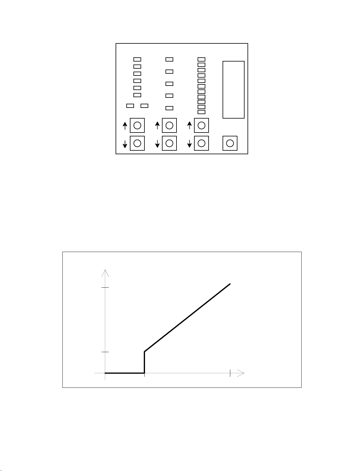
Built-in to the R1300+ is a Set-Up Panel (see Figure 7) consisting of three
columns of indicator lights, seven push buttons, and a socket for a plug-in “key”. As
shown in the diagram below, there are five configurable parameters (centre column of
lights) for each proportional (pulse-width modulation, PWM) output: Threshold,
Start PWM, Max PWM, Ramp Up, and Ramp Down.
The Set-Up Panel has “Output” lights 1+ to 6- which correspond directly to the
proportional outputs of the R1300+. For adjustment of the proportional outputs of the
S20, the Output lights are re-used as per the “Set-Up Panel Indicator” column in the
above table.
Set-Up Panel
Indicator
Function
The 12 R1300+ proportional outputs are indicated by the lights in the “Output”
column as follows: When the “1_” and “+” lights are solidly on, the 1+ parameter is
being output is being adjusted. The “1_” and “-” lights indicate 1-, and so on. The table
above lists these as “Solid 1+” through “Solid 6-“.
The first 12 S20 proportional outputs (O1 through O12) are indicated by flashing
“1+” through flashing “6-”. The table above lists these as “Flashing 1+” through
“Flashing 6-”.
The last 4 outputs (O13 through O16) of the S20 are indicated by the “1_” through
“4_” lights solidly on with both the “+” and “-” lights off. The table above lists these as
“Solid 1” through “Solid 4”.
21
Page 28
T245 Control System Manual
Output Param Value
1_
2_
3_
4_
5_
6_
+-
Threshold
Start PWM
Max PWM
Ramp Up
Ramp Down
MAX
MIN
Key
Store
Figure 7
R1300+ Set-Up Panel
The Ramp parameters control how fast the output builds up or down to the final
value according to a first-order difference equation. The separate Ramp Up and
Ramp Down time constants allow you to tune the valve response for smooth, non-jerky
actuation. The Threshold, Start PWM, and Max PWM parameters control the transferfunction from input (joystick position) to PWM-output value, as shown in Figure 8. The
joystick position can go from 0 to 127. The threshold is simply the deadband beyond
which the joystick must move in order to actuate the PWM output. The PWM output
starts at Start PWM as soon as the joystick has exceeded the threshold, and maps linearly
with joystick position up to Max PWM.
PWM Output
Max PWM
Start PWM
0
0
Threshold 127
Figure 8
Proportional (PWM) Output Function
Joystick Posit
22
Page 29

T245 Control System Manual
In order to customize various parameters for the PWM outputs, the configuration
panel must be “enabled” by plugging in the Factory Key or User Key (supplied); you will
then be in Proportional Drive Setup mode. The display will initially be displaying
“Output” 1 +, no “Param” lights will be illuminated, and the “Value” lights will be
displaying the Start PWM and Max PWM as solid lights. Also, a flashing “Value” light
will show the actual function output value. The flashing light will move as the
corresponding joystick is moved, and you will also see the green light next to the 1+
output on J6 go brighter and dimmer.
To select the output pin you want to change parameters for, press the buttons
under the “Output” lights. To change a parameter, press the buttons under the “Param”
lights until the desired parameter is lit up (Threshold, Start PWM, Max PWM, Ramp Up,
Ramp Down). The “Value” lights will now indicate where the selected parameter is
currently set, in relation to the MAX and MIN values allowed for that particular
parameter (see table below). Press the buttons below the “Value” lights to raise or lower
the parameter; if the value of the parameter is “in between” two lights, the two adjacent
lights will both be on at once, each with relative brightness corresponding to how far in
between the two lights the value is. To change a parameter a long way, press and hold the
button and it will auto-repeat as on a computer keyboard.
The table below indicates the minimum, maximum, and increment values for each
of the proportional drive adjustments. The default values for each parameter are specific
to each proportional output and are not listed.
Parameter Minimum Maximum Increment
Threshold 0 (out of 127) 40 (out of 127) 1
Start PWM 0% lesser of 100% and
Max PWM
Minimum setting
Max PWM greater of 0% and
Start PWM
Maximum setting
Ramp Up 0 ms 1054 ms 34 ms
Ramp Down 0 ms 1054 ms 34 ms
100% 1%
1%
23
Page 30

T245 Control System Manual
As you are adjusting any of the parameters, you can “try” the new setting right
away by moving the joystick and watching the hydraulic/pneumatic response. A very
good way to tune the proportional parameters is to have someone watch the override
handles on the hydraulic valves (or the cylinder or bellows in a pneumatic system) as you
operate the joystick from “just-on” to “full-on”; for best metering action, adjust the Start
PWM and Max PWM such that the whole travel of the joystick corresponds to full travel
of the override handle, with no “dead” region at the start or end of the joystick travel.
Note: It is very important that the proportional drive frequency be correct for the
type of valve installed in your system. Please see the next chapter for information
on how to set the drive frequency, and make sure it is correct before attempting to
adjust the PWM output parameters.
When you are satisfied with the way the parameters are set up, press the “Store”
button. All of the lights will come on to indicate that the new parameters have been
stored. If you wish not to save the changes you have made, simply unplug the key. Then,
you can plug the key back in and start again from the original settings. If you have stored
a set of new parameters which are so far off from values which the machine will operate
with, press and hold the “Store” button until all the lights begin to flash. Release the
button and all of the Proportional Drive parameters will be reset to factory-default values.
Important
set-up procedure. Leaving the key in may allow someone to change the parameters
accidentally, as well as allow the long-term vibration of the vehicle to damage the key.
: The key should not be left plugged in after you have completed the
24
Page 31

T245 Control System Manual
9. Factory Parameters
The Control System has a number of “Factory Parameters” which may be
configured to match the model of valves installed in the machine, and to set the load
limit. They are called “Factory Parameters” because they are usually set at your factory
before the machine is shipped to the end customer. In the application, the first 4
Factory Parameters are PWM drive frequencies for the various “banks” of proportional
outputs, and the rest of the Factory Parameters set boom load moment limits and speeds
of special functions.
In the general discussion below, reference is made to “up to 48 Factory
Parameters”, which means more parameters may be added in the future, if required.
9.1. Types of Factory Parameters
There are only two types of factory parameters. The first type of parameter is a
“multiple-choice” selection; the “PWM Drive Frequency for S20 Proportional Outputs
O1 through O8” parameter is an example of a multiple-choice parameter—you set it by
selecting one of 5 different frequencies.
The second type of factory parameter is a “variable-value” adjustment with a
minimum and maximum value. Examples of such a parameter are the Boom Derating
factors; you set between 20% and 150% in 2% increments.
9.2. Changing the Factory Parameters
To change or view the Factory Parameters, use the following procedure:
1. Plug the Factory Key (the User Key will not allow you to enter Factory Setup Mode)
into the R1300 Controller board’s Set-up Panel; you will be in Proportional Drive
Setup mode. Enter Factory Setup mode by momentarily pressing the two lower lefthand buttons together; the light display will change.
2. There can be up to 48 Factory Parameters. Pressing the up and down buttons at the
bottom of the “Output” column changes the parameter you are accessing. The first 12
are indicated by the lights in the “Output” column as follows: When the “1_” and “+”
lights are on, the first parameter is being accessed. The “1_” and “-” lights indicate
the second parameter, “2+” indicates the third, “2-” indicates the fourth, etc. down to
“6-” which is the 12th parameter. The next 12 parameters are indicated by flashing
“1+” through flashing “6-”.
The next 6 parameters are indicated by the “1_” through “6_” lights solidly on with
both the “+” and “-” lights off. The next 6 are indicated by “1_” through “6_” solidly
on with both the “+” and “-” lights on.
The next 6 parameters are indicated by flashing “1_” through flashing “6_” with both
the “+” and “-” lights off. The last 6 parameters are indicated by flashing “1_”
through flashing “6_” with both the “+” and “-” lights also flashing.
25
Page 32

T245 Control System Manual
3. To change or view a particular Factory Parameter, press the up or down Output
buttons until you reach the desired parameter (see table below). Note that if you press
the up button when you are already at the “top” (parameter 1, solid “1+”), the display
will “wrap around” to the last parameter (parameter 48, flashing “6±”). A similar
wrap-around happens when you press the down button when you are already at the
last parameter.
4. The display will show one light on in the “Param” column if the selected parameter is
a “multiple-choice” type, or one or two lights in the “Value” bar graph if the
parameter is a “variable-value” type. You change the multiple-choice selection using
the buttons under the “Param” lights, and the variable-value using the buttons under
the “Value” lights. For multiple-choice parameters, the top Param light (“Threshold”)
through the bottom light (“Ramp Down”) are referred to in the table as choices “A”
through “E”.
When changing a variable-value parameter, note that the top Value light (“MAX”)
corresponds to the maximum value allowed for that parameter (see table below), and
the bottom (“MIN”) corresponds to the minimum value allowed. Each single press of
the Value up or down buttons will change the parameter by the increment value for
that parameter. Holding down either button will cause it to automatically repeat, and
is useful when you need to change a value a long way from where it is.
If you are adjusting either of the Boom Derating Factors, the numeric display on the
T45 or T47 will show the value (in percent) of the parameter you are adjusting, with
no pointers (LOAD %, DIAG1, DIAG2) showing.
5. When you are done changing the parameters, press the Store button to save the new
Factory Parameters. If you do not want to save your changes, remove the Factory
Key. If you want to restore the Factory Parameters to the preprogrammed factorydefault settings, press and hold the Store button until all the lights begin flashing; only
the Factory Parameters are affected--the Proportional Drive Settings can only be reset
by holding the Store button in Proportional Drive Setup Mode.
6. You can now remove the Factory Key or simultaneously press the two lower-left hand
buttons again to get back to Proportional Drive Setup mode.
9.3. List of Factory Parameters
The following table lists the Control System Factory Parameters. For each
parameter, the corresponding light display in the Output column is shown, together with
the Minimum, Maximum, Adjustment Increment, and Default Value. The last two
columns in the table indicate other adjustment restrictions for the parameter; some
parameters may be constrained by the values of other parameters.
An explanation of the parameters whose function is not immediately obvious
follows the table.
26
Page 33

T245 Control System Manual
Parameter Display Type Min. Max. Increm. Default Cannot Go Below Cannot Go Above
PWM Drive Frequency
for R1300 Proportional
Outputs 1+/- through
4+/-
PWM Drive Frequency
for R1300 Proportional
Outputs 5+/- and 6+/-
PWM Drive Frequency
for S20 Proportional
Outputs O1 through O8
PWM Drive Frequency
for S20 Proportional
Outputs O9 through O16
Solid 1+ Mult.-
Choice
Solid 1- Mult.-
Choice
Solid 2+ Mult.-
Choice
Solid 2- Mult.-
Choice
A = 33 Hz
B = 50 Hz
C = 80 Hz
D = 125 Hz
E = 250 Hz
A = 33 Hz
B = 50 Hz
C = 80 Hz
D = 125 Hz
E = 250 Hz
A = 33 Hz
B = 50 Hz
C = 80 Hz
D = 125 Hz
E = 250 Hz
A = 33 Hz
B = 50 Hz
C = 80 Hz
D = 125 Hz
E = 250 Hz
AN/A N/A
AN/A N/A
AN/A N/A
EN/A N/A
Boom Load Moment
Limit
Boom Derating Factor,
Ground Operation (%)
Solid 3+ Mult.-
Choice
Solid 3- Variable
Value
A = 2500000 inch-lbs A N/A N/A
20 150 2 84 N/A N/A
27
Page 34

T245 Control System Manual
Parameter Display Type Min. Max. Increm. Default Cannot Go Below Cannot Go Above
Boom Derating Factor,
Platform Operation (%)
Emergency Override
Panel Function Speed
(%)
Auger Shake Speed (%) Solid 5+ Variable
Digger Transmission
Type
Bucket/Pole-Claw Speed
Ratio
Solid 4+ Variable
Value
Solid 4- Variable
Value
Value
Solid 5- Mult.-
Choice
Solid 6+ Variable
Value
20 150 2 66 N/A N/A
5 100 5 25 N/A N/A
5 100 5 100 N/A N/A
A = Two-Speed
B = Hydrasync
25 75 5 30 N/A N/A
AN/A N/A
28
Page 35

T245 Control System Manual
PWM Drive Frequency Parameters
These 4 parameters allow you to use the Receiver/Controller in heterogeneous
valve systems. Grouping valves requiring different drive frequencies into separate banks,
you can provide each valve with the drive frequency most suited to it.
Boom Load Moment Limit
This parameter allows you to select from up to five load moment limits to match
the exact model of digger derrick on which you are installing the Control System.
Boom Derating Factors
These parameters are used to multiply (in percent) the
to determine the actual load limit for the boom. There are two separate factors; one
Limit
is for ground operation and the other for platform operation.
When you are adjusting these parameters, the T245/T45 or T247 numeric display
will show the value (in percent) of the parameter you are adjusting, with no pointers
(
LOAD %, DIAG1, DIAG2
Emergency Override Panel Function Speed
This parameter determines the speed of the proportional functions when operated
from the toggle switches on the Emergency Override Panel.
Auger Shake Speed
This parameter determines the speed of the digger when operated from the Auger
Shake toggle switch.
Digger Transmission Type
This parameter is used to determine if the auger must be stopped while shifting
speeds. Hydrasync diggers can be shifted “on the fly”, while two-speed diggers cannot.
When the Two-Speed digger is selected, the DIGGER SHIFT functions will
automatically stop the auger, perform a shift, and then restart the auger.
) showing
Boom Load Moment
Bucket/Pole-Claw Speed Ratio
When the T245 Transmitter is holstered in the bucket, the bucket speed will be
automatically set to this percentage of the pole-claw speed.
29
Page 36

T245 Control System Manual
10. Warranty
OMNEX Control Systems Inc. Warrants to the original purchaser that the OMNEX
products are free from defects in materials and workmanship under normal use and
service for a period of
OR PARTS SUBJECT TO UNAUTHORIZED REPAIR OR MODIFICATION) and
labor from the date of delivery as evidenced by a copy of the receipt. OMNEX’s entire
liability and your exclusive remedy shall be, at OMNEX’s option, either the (a) repair or
(b) replacement of the OMNEX product which is returned within the warranty period to
OMNEX freight
receipt and with the
accident, abuse or misapplication, OMNEX shall have no responsibility to repair or
replace the product under warranty. In no event shall OMNEX be responsible for
incidental or consequential damage caused by defects in its products, whether such
damage occurs or is discovered before or after replacement or repair and whether or not
such damage is caused by the negligence of OMNEX Control Systems Inc.
Neither OMNEX nor its Distributors shall be liable for any delay or failure of the
performance of any of its obligations under this agreement caused by acts of God, labor
disputes, embargoes, boycotts, shortage of parts or any cause beyond its reasonable
control.
ONE YEAR,
collect
by the OMNEX
return authorization
parts (EXCLUDING: SWITCHES, CRYSTALS,
APPROVED
of OMNEX. If failure has resulted from
carrier with a copy of the purchase
Neither OMNEX nor its Distributors shall be responsible for incurred costs associated
with border clearance or with the delay of the OMNEX products in transit to OMNEX.
Any charges associated with the return of the OMNEX products may be subject to billing
to the original purchaser in the event that the OMNEX products are NOT covered by the
warranty as noted above.
30
 Loading...