

Page 1
MODEL R1300
RADIO CONTROL SYSTEM
FOR
ALTEC AD108 TRAILER REEL
#74 - 1833 COAST MERIDIAN ROAD PORT COQUITLAM, B.C. V3C 6G5
PHONE (604)944-9247 FAX (604)944-9267
Page 2

CONTENTS
INSTALLATION
RECEIVER 3-4
ANTENNA 3
RECEIVER WIRING 4
OPERATION
TRANSMITTER 5
RECEIVER 6-7
BASIC TROUBLESHOOTING
Important User Information
This device complies with Part 15 of the FCC Rules. Operation is subject to the following two conditions:
(1) This device may not cause harmful interference, and (2) this device must accept any interference
received, including that which may cause undesired operation.
Changes or modifications not expressly approved by OMNEX Control Systems Inc. can void the users
authority to operate this equipment!
8-9
MOUNTING THE RECEIVER:
INSTALLATION
2
Page 3
Select a suitable location on the machine that will protect the receiver box fr om impact dam age. A loc ation
that protects the receiver from direct exposure to the weather is desirable. If the box must be located
outside, mount it with the power and antenna cables facing down to allow water to drain away.
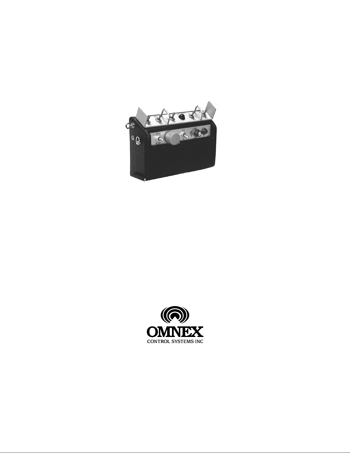
! IMPORTANT:
The receiver box is supplied with rubber shock mounts to prevent damage from shock or vibration. Be
sure to install the shock mounts on machines that vibrate during operation or transport! Use only the
mounting flanges provided on the box. Do not drill into the receiver box!
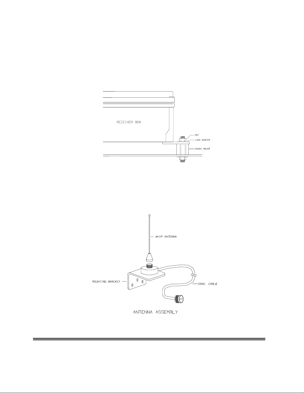
MOUNTING THE RECEIVER ANTENNA:
The receiver antenna assembly consists of a mounting bracket with attached coax. cable, and a
removable whip antenna. The mounting brack et should be located as high as possible on the outside of
the machine such that the whip antenna is vertical. The bracket m ay be bolted to the metal frame but do
not allow the antenna whip to contact metal parts.
RECEIVER WIRING:
INSTALLATION
3
Page 4

The receiver box is supplied with a 3 ft. "pigtail" cable that must be connected to the machine remote
control interface. The wires in the pigtail cable are individually labeled as to function. The following chart
relates the receiver connector wiring to the machine functions:
FUNCTION CONNNECTOR PIN #
Ground A
-B
+12 Volt Power In* C
-D
-E
Function Speed F
-G
Wheels FWD. H
Wheels REV. J
Reels PAY IN K
Reels PAY OUT L
Carriage LOAD M
Carriage UNLOAD N
Steer LEFT P
Steer RIGHT R
-S
-T
-U
-V
-W
-X
-Z
-a
-b
-c
ST/SIDE IN d
ST/SIDE OUT e
CB/SIDE IN f
CB/SIDE OUT g
-h
-j
-k
HI/LO ON m
-n
-p
+12 Volt Power In * r
-s
* Both power wires (C and r) must be connected to 12 volts for proper operation.
The receiver also contains a separate ground lug and wire. Connect the ground lug to a solid, clean
ground point on the machine.
OPERATION
TRANSMITTER:
Switching the Transmitter ON and OFF:
4
Page 5

To switch on the transmitter first release the red STOP button by turning clockwise, then momentarily
press the ON button. (The transmitter will not switch on if the STOP button is depressed). The ON light will
glow red indicating the transmitter is on and ready to use. The receiver will now respond to the function
switches. W hen finished operating depr ess the STO P button to switch of f the transm itter and dis able the
receiver output relays.
Enable Button:
The W heels and Reels switches will not operate unless the Enable button is also press ed "at the same
time".
Auto Shut-Off:
The transmitter incorporates an auto shut-off feature. If no control switches are operated over a three
minute period, the transmitter will switch off autom atically. The ON switch mus t then be pressed again to
resume operation.
Battery Indicator:
The ON light is also used to indicate battery level. When the light is solidly on, the battery level is
acceptable. If it blinks, the batteries require charging.
Charging the Transmitter Battery:
The transmitter is powered by a standard 9.6V Makita power tool battery, and a Makita charger is supplied
to re-charge the battery. Please read the instructions provided with the Makita c harger. To remove the
battery, grasp the ring on the battery door and turn counter-clockwise to release the locking m echanism.
The door may now be opened and the case tilted to allow the battery to slide out. (A slight "tap" is
sometimes necessary to dislodge the battery from the contact terminals.)
MAKITA BATTERY
OPERATION
RECEIVER:
The receiver will be operational when power is applied. It does not contain a power switch. Three LED
indicator lights on the lid are used to verify proper operation. The lights are labeled Power, ID and Link and
function as follows:
5
Page 6

POWER:
Indicates that 12 volt DC power is applied to the receiver.
ID:
Indicates that information f rom the transmitter is being suc cessfully received. If the light flickers
occasionally this indicates that interference is present on s om e fr equencies. T his is not a pr oblem
since this is a spread spectrum system and changes frequency many times each second.
LINK:
Indicates that the radio link between the transmitter and receiver is reliable. If the link is not
reliable, power is removed from the receiver output drivers.
CONFIGURING THE PROPORTIONAL SPEED OUTPUT:
The receiver contains a configuration panel that allows you to customize the operation of the function
speed control. The panel appears as shown below:
To enable the configuration panel, plug in the user configuration key supplied. The dis play will initially be
displaying "Output" 1 + , no "Param" lights will be illuminated, and the "Value" lights will be displaying the
Start PWM and MAX PWM as solid lights, and the ac tual speed output as a flashing light. The flashing
light will move as the speed dial on the transm itter is rotated. You will also see the green light next to the
1+ output go brighter and dimmer.
OPERATION
Note: You will notice that the control panel has 6 "output" lights. This is bec ause the r ec eiv er is c apable of
controlling the parameters for up to 6 proportional functions. In this particular application, however, only a
single proportional output is needed, and this has been assigned to output #1. Also, the Parameter setting
options: Threshold, Ramp Up and Ramp Down, will not apply to the simple potentiometer control provided
on the Altec system. (These are used in other applications that require joystick type controls). In
6
Page 7

this application, only the Start PWM and Max PWM will be of concern. These s et the endpoints (min and
max) of the speed potentiometer.
To change a parameter, press the buttons under the "Param " lights until the desir ed param eter is lit up. In
this application select only Start PW M or Max PWM. The other selections do not apply! The "Value" lights
will now show one solid light indicating where the selected parameter is cur rently set, in relation to the
MAX and MIN values allowed for that particular param eter. Press the buttons below the "Value" lights to
raise or lower the parameter. Note that the light may not move for each time you press a button, but that
the parameter is actually changing (there are not enough lights to show every step). To change a
parameter a long way, press and hold the button and it will auto-repeat as on a computer keyboard.
When you are happy with the way the parameters are set up, press the "Store" button. All of the lights will
come on to indicate that the new parameters have been stored. If you wish not to save the changes you
have made, simply unplug the key, then, you can plug the key back in and start again from the or iginal
settings. If you have stored a new set of parameters which are s o far off fr om values which the machine
will operate with, press and hold the "Store" button until all the lights begin to flash. Release the button and
all of the parameters will be reset to factory default values.
IMPORTANT: Do not leave the key plugged in after you have completed the set-up procedure. Leaving
the key may allow someone to change the parameters accidentally, as well as allow long term vibration to
damage the key.
BASIC TROUBLESHOOTING
The most com mon cause for a previously operating system not to respond is a low transm itter battery.
Always check the battery indicator light first. If it is blink ing, or does not light at all, replace the batter y with
a charged one and try again. If the battery indicator does not light with a good battery, a transmitter fault is
indicated requiring factory repair. The trans m itter contains no us er ser viceable parts . (Also rem em ber that
the transmitter will not operate if the red STOP button has been depressed. Check this!) If the battery
indicator lights and the system still does not res pond, proceed with the following steps to help isolate the
problem:
STEP ONE:
7
Page 8

Check the Power, ID and Link lights on the lid of receiver. With the transm itter switched OFF only the red
Power light should be on. When the transm itter is switched ON, the ID and Link lights should also come
on. If this is so, proceed to step two. If the lights do not operate, open the lid of the receiver box . Inside
you will find a radio receiver module on the lid and a circuit board inside. Located on the circ uit board are
two green lights labeled as DRIVE PW R and MICRO PW R (Do not be concerned with the flashing lights
on the configuration panel). When power is applied to the r eceiver, and the transm itter switched O N, both
these lights should be on. If so proceed to step two. If not, check the condition of 10 amp. fuses F2 and F3
on the circuit board. Disconnect power to the receiver before removing f uses! A fuse that keeps blowing
indicates a short circuit, check the wiring car efully. If the fuses are OK a c ircuit f ault on the c ircuit board is
indicated.
STEP TWO:
Observe the red and green lights on the red receiver module located on the inside of the lid. With the
transmitter switched OFF , only the red light should be on. If it is not a receiver fault is indicated. If the r ed
light is on, switch on the transmitter. The green light s hould now also be on. If it is pr oc eed to step thr ee. If
not, a fault could exist in either the transmitter or receiver.
STEP THREE:
Observe the green lights located in a long row along one side of the circuit board while operating the
various transmitter controls. Each machine function will have an associated light as indicated in the
following chart. W hen operating proportional functions , the lights will change in intensity. Digital f unctions
will just switch on or off.
MACHINE FUNCTIONS VS RECEIVER INDICATOR LIGHTS:
FUNCTION INDICATOR LIGHT
Function Speed 1+
Wheels FWD. 2+
Wheels REV 2-
Reels PAY IN 3+
Reels PAY OUT 3-
Carriage LOAD 4+
Carriage UNLOAD 4-
Steer LEFT 5+
Steer RIGHT 5-
ST/SIDE IN D1
ST/SIDE OUT D2
CB/SIDE IN D3
CB/SIDE OUT D4
HI/LO ON D8
WARRANTY
OMNEX CONTROL SYSTEMS INC. Warrants to the original purchaser that the OMNEX
radio remote control system is free from defects in materials and workmanship under normal use
and service for a period of ONE YEAR parts (EXCLUDING: SWITCHES, CRYSTALS, OR
8
Page 9

PARTS SUBJECTED TO UNAUTHORIZED REPAIR OR MODIFICATION) and labor
from the date of delivery as evidenced by a copy of the receipt. OMNEX's entire liability and
your exclusive remedy shall be, at OMNEX's option, either the (a) repair or (b) replacement of
the OMNEX radio control system, which is returned to OMNEX freight prepaid with a copy of
the receipt. If failure has resulted from accident, abuse or misapplication, OMNEX shall have no
responsibility to repair or replace. In no event shall OMNEX be responsible for incidental or
consequential damage caused by defects in its products, whether such damage occurs or is
discovered before or after replacement or repair, and whether or not such damage is caused by
the negligence of OMNEX CONTROL SYSTEMS INC.
Neither OMNEX nor its Distributor shall be liable for any delay or failure in the performance of
any of its obligations under this agreement caused by acts of God, strikes, other labor
disturbances, embargoes, boycotts, shortage of parts or any cause beyond its reasonable control.
9
 Loading...