

Page 1
DTW 400/DTW 405 - Digital Torque Tester/Screwdriver User’s Guide
LIST OF EQUIPMENT
1. Digital Torque Tester/Screwdriver (DTW 400 with CW and CCW ratchet (1/4” female hex)
2. 2 Phillips tips (DTW 405 with CW stepless one-way clutch Phillips tip)
3. AC adapter/charger
4. Carrying case
DTW Digital Torque Tester Ranges Accuracy ± 0.5% F.S., ± 1 LSD
Capacity
Ozf-in Lbf-in Kgf-cm N-cm N-m
DTW 405 0.20~69.50 0.020~4.500 0.020~5.000 0.20~50.00 DTW 400 2.0~560.0 0.20~35.00 0.20~40.00 2.0~400.0 0.2~4.000
READ FIRST: SAFETY INFORMATION
For safety, and for damage avoidance, be sure to read this manual thoroughly. The warranty is only valid when
the product is used following the instructions provided within this manual.
• Do not use tester in high temperature, high humidity, or in damp or wet areas.
• Recommended operating temperature is between 0-42ºC (32-100ºF).
• Do not apply torque exceeding the rated capacity (35 lbf-in), regardless of whether the unit is On or Off.
Avoid shock load.
• When charging the battery, be sure to use the provided AC adapter/charger exclusively.
• Do not use lacquer thinner or any solvent to clean the unit.
• Do not disassemble or modify the unit.
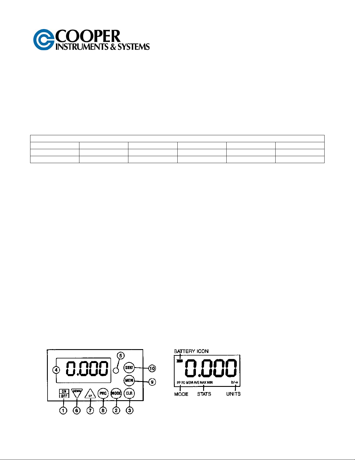
1. ON/OFF Switch Press to turn on, press again to turn off (click once, do not hold). After 10 minutes of non use the unit shuts off.
2. MODE Select Real Time, PP (Peak) PD (Peak Down), C (Continuous Output Mode)
3. CLEAR To reset display to zero and send data to memory.
4. LCD Display Displays torque value, battery icon, mode & units.
5. GO/NG Indicator Green for values between LO and HI setpoints, flashing red for values above HI, solid
green for data output.
6. DOWN Change values or numeric places.
7. UP Change values or options
8. PRG Enter programming mode or enter values
9. MEM Display memory locations and date
10. STAT Display statistics; number of records, Max, Min and Ave.
CF132 DTW 400/405 1 11/12
Page 2
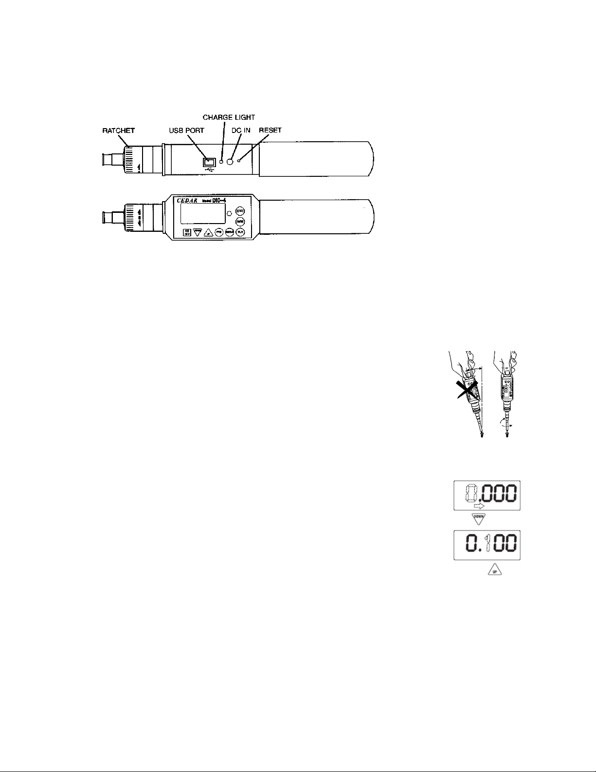
Ratchet Operation CW, CCW and fixed positions
USB virtual COM port Send data to computer via USB cable
Charge Light lights when charging, off when complete
DC IN AC charger/adapter receptacle
RESET System reset button
GENERAL OPERATION
1. Press and hold MODE for one second to select from the following Measuring Modes.
REAL TIME – Displays torque transients (no output or indicator)
PP Mode – Peak, captures peak torque) peak data output, PP appears on the display)
PD Mode – First Peak, capture first peak value, (peak data output, PD appears on the display)
C Mode – Continuous RS-232 out display and output torque transient (180 d ata/sec., C appears on the
display.)
2. Insert Phillips tip into the screwdriver.
3. To select ratchet operation turn the ratchet one click CW or CCW from the center
position. To disable ratcheting, turn it so the semi circle is in the center position.
4. Press the CLEAR button on the display unit to zero the display. Insert the screwdriver
tip into the screw, hold perpendicularly (not at an angle) and turn to measure.
5. After measuring, press CLEAR to zero the display for the next test.
PROGRAMMING
Press POWER to turn on. Press PRG for one second. The display shows “HI” and then
the High setpoint value. This confirms the tester is ready for the following programming
steps:
1. High Setpoint (HI)
After “HI” is displayed and the High setpoint value, press DOWN (6) to move the
numeric place and press UP (7) to select values i.e. 50.0 for 50.0 lf-in, then press
PRG (8) to enter.
2. Low Setpoint (LO)
After High value is entered, “LO” is displayed, then the Low setpoint value. Press
DOWN to move the numeric place and press to select values, then press PRG to
enter.
3. Peak Down Minimum (PdLO)
After Low value is entered, “PdLO” is displayed and then the PdLO value. Press
DOWN to move the numeric place and press to select values, then press PRG to enter.
PdLO sets a minimum torque value for Peak Down mode. For example if “PdLO” value is set at 5.0 lbf-in,
only a reading over 5.0 lbf-in will be measured in Peak Down mode.
4. Continuous Data Output Minimum (CLO)
After Peak Down value is entered, “CLO” is displayed, then the CLO value. Press DOWN to move the
numeric place and press to select values, then press PRG to enter.
CLO sets the start and stop trigger points for continuous data output. When torque reaches the CLO value,
the tester starts to output data and stops if torque falls below the value. NOTE: the display does not show
any value below the CLO minimum.
CF132 DTW 400/405 2 11/12
Page 3

5. Auto Zero Reset (AC)
After Continuous Data Output Output Minimum is entered, “AC” is displayed and the Auto Zero Reset
duration value. Press UP or DOWN to select 0.0C – 0.1C – 0.5C – 1.0C – 1.5C – 2.0C – 2.5C – 3.0C, and
press PRG to enter (0.1C for 0.1 second and 0.0C for manual reset
After measuring, Auto Zero automatically resets the tester to 0.0.
6. Batch Counter
After the Auto Zero value is entered, “CO” is displayed, then the CO value. Use th UP or DOWN keys to
select a value and press PRG to enter (0-99 clockwise only)
7. Interval (In)
After the Batch Counter value is entered, “IN” is displayed then the IN value. Use the UP or DOWN keys to
select a value and press PRG to enter (0-24 seconds in 2 second increments.)
8. Beeper (bp)
After Interval value is entered, “bp” is displayed then “On”. Press UP or DOWN to select On, OFF or FF,
then press PRG to enter.
“On” – beeper sounds for Good, NG and capacity overload
“OFF” - beeper sounds for capacity overload only
“FF” – beeper sounds for NG and capacity overload
9. Units (Un)
After the Beeper is programmed, “Un” is displayed, then the current unit selection. Press UP to cycle the
units; lbf-in, ozf-in, kgf-in, N-m and N-cm
After Units are entered, “-S-“ is displayed to confirm programming completion an d zero is shown.
After High and Low setpoints are set and beeper in set to ON
In PP Mode
Under LO setpoint – no LED light or beep
Over LO – Green LED lights
Over HI – Red LED flashes and beep sounds
In PD mode – no indicator or beep for values before Peak Down is sensed.
Under LO setpoint – Red LED flashes and slow beep sounds
Over LO – Green LED lights and constant tone sounds
Over HI – Red LED flashes and fast beep sounds
In Real Time and C Mode
Under LO setpoint – no LED light or beep
Over LO – Green LED lights and beep sounds
Over HI – Red LED lights and beep sounds
DATA MEMORY
Storing and Recalling Data from Memory
Memory functions work in PP and PD modes. Store up to 800 values in memory.
1. Measure in PP or PD mode, when the display resets by either Auto Zero or manually pressing CLR, the
peak value is stored.
2. To recall a value, press MEM and the last stored memory is displayed. Press UP or DOWN to select a
memory location (i.e. .0.01 for first location) and torque value. The display cycles between memory
location and value.
Clearing Data from Memory
Single clear: Press MEM then press UP or DOWN to move to a memory location. When the desired memory
value is displayed, press CLR, “CLR” is displayed. Press CLR again to clear the data and “----“ is displayed to
confirm deletion.
All clear: Press CLR and hold until the display shows “ALL” then press CLR. While CLR is blinking, press CLR
again and “----“ is displayed to confirm deletion.
CF132 DTW 400/405 3 11/12
Page 4

Downloading Memory Data
1. Press ON/OFF to turn on.
2. Press MEM and after memory data is displayed, press MEM again and “FA” is displayed. Use UP and
DOWN to select the first memory location then press MEM and “LA” is displayed. Use UP or DOWN to
select the last memory location. Press MEM again and the data is sent, While data is output, -P- is
displayed.
Note: By pressing DOWN switch for more than 1 sec, the download function can be terminated.
Statistics
Press Statistics and the number of data, Max, Min, and Avg are displayed in sequence.
Auto Power Off
To maximize the life of the battery, power automatically shuts off after 10 minutes of non-use.
Low Battery Indicator
Battery indicator status shows full, half or needs recharging. If the battery is empty, power is
turned off immediately.
IMPORTANT! Use the provided AC adapter/charger exclusively and plug into the correct AC output. It takes 5
hours to fully recharge for 12 hours of continuous use. When fully charged, the charge light goes off,
System Reset
When battery power is completely depleted, the tester may not work even though it has been recharged. In this
case, press the System Reset Button.
OUTPUT
USB Virtual COM Port
When the tested is connected to a computer’s USB port and turned
on, Windows XP or Vista will recognize the tester and ask to connect
to the Internet. Allow Windows Update to connect, and follow the
instructions on the screen to download and install two drivers for the
USB virtual com port. For Windows 98, ME and MAC, go to
www.ftdichip.com/Drivers/VCP.htm.
The PC and tester will communicate through the USB port the same as a
com port. To verify the COM port, open the Device Manager.
CF132 DTW 400/405 4 11/12
Page 5

Output is available in PD, PP and C modes. In PD and PP modes, peak data is output when ZERO is pressed
or activated by the AUTO ZERO function. In C mode, the gauge outputs data continuously 160 data / second.
Comport signal
8 data, 2 stop, no parity. Baud rate: 19,200 bps
Output connector
USB A/B cable
Peak Data Output Format
[CAN] _ _ _ [SO] [value] _ [SI] [unit] [CR]
( _ _ _ is memory location)
[CAN]: ASCII control code 24
_: Space (code 32)
[SO]: ASCII control code 14
[value]: Output data with sign and decimal point. Plus sign represents CW torque and mi nus
sign for CCW. [value] always occupies six locations and empty locations will be filled
with spaces.
[SI]: ASCII control code 15
[unit]: N*m _ _ _=N·m
kgf*cm=kg·cm
lb*in=lb·in
[CR]: ASCII control code 13 (Carriage Return)
Continuous Output Data Format
[CAN] [value] [CR]
Changing the Continuous Output Data Rate
1. Turn the tester off.
2. Click ON/OFF while holding PRG, “00” is displayed.
3. Press UP to select either “00” or “01”.
00 = 12 data/second
01 = 180 data/second
4. Press PRG to save and exit.
CF132 DTW 400/405 5 11/12
Page 6

WARRANTY REPAIR POLICY
Limited Warranty on Products
Any Cooper Instruments product which, under normal operating conditions, proves defective in material or in
workmanship within one year of the date of shipment by Cooper will be repaired or replaced free of charge
provided that a return material authorization is obtained from Cooper and the defective product is sent,
transportation charges prepaid, with notice of the defect, and it is established that the product has been properly
installed, maintained, and operated within the limits of rated and normal usage. Replacement or repaired
product will be shipped F.O.B. from our plant. The terms of this warranty do not extend to any product or part
thereof which, under normal usage, has an inherently shorter useful life than one year. The replacement
warranty detailed here is the buyer’s exclusive remedy, and will satisfy all obligations of Cooper whether based
on contract, negligence, or otherwise. Cooper is not responsible for any incidental or consequential loss or
damage which might result from a failure of any and all other warranties, express or implied, including implied
warranty of merchantability or fitness for particular purpose. Any unauthorized disassembly or attempt to repair
voids this warranty.
Obtaining Service under Warranty
Advance authorization is required prior to the return to Cooper Instruments. Before returning the item, contact
the Repair Department c/o Cooper Instruments at (540) 349-4746 for a Return Material Autho r ization number.
Shipment to Cooper shall be at buyer’s expense and repaired or replacement items will be shipped F.O.B. from
our plant in Warrenton, Virginia. Non-verified problems or defects may be subject to a $100 evaluation charge.
Please return the original calibration data with the unit.
Repair Warranty
All repairs of Cooper products are warranted for a period of 90 days from date of shipment. This warranty
applies only to those items that were found defective and repaired; it does not apply to products in which no
defect was found and returned as is or merely recalibrated. It may be possible for out-of-warranty products to
be returned to the exact original specifications or dimensions.
* Technical description of the defect: In order to properly repair a product, it is absolutely necessary for Cooper
to receive information specifying the reason the product is being returned. Specific test data, written
observations on the failure and the specific corrective action you require are needed.
CF132 DTW 400/405 6 11/12
 Loading...