

Page 1

TSFM500-DC Digital Controllers Series DC
User’s Guide
Page 2

Table of Contents
1 LIST OF INCLUDED ITEMS....................................................................................................................1
2 OVERVIEW ...............................................................................................................................................1
3 MECHANICAL SETUP & SAFETY.........................................................................................................1
4 CONTROLS LAYOUT..............................................................................................................................3
5 TEST PARAMETER SETUP......................................................................................................... ............4
6 OPERATING MODES.............................................................................................................................13
7 COMMUNICATING WITH MESURGAUGE........................................................................................18
8 SPECIFICATIONS...................................................................................................................................18
9 DIMENSIONS..........................................................................................................................................19
10 WARRANTY..........................................................................................................................................19
TSFM 500 DC ii 32-1101 REV 2 0710
Page 3
Thank you for purchasing a Mark-10 Series DC digital test stand controller, designed for use with Mark-10 motorized test
stands. Mark-10 test stands and controllers are ruggedly built for many years of service in laboratory and industrial
environments.
This User’s Guide provides setup, safety, and operation instructions for the digital controller. Dimensio ns and
specifications are also provided. Instructions for the test stand may be found in a separate user’s guide.
For additional information or answers to your questions, please do not hesitate to contact us. Our technical support and
engineering teams are eager to assist you.
Before use, each person who is to use a Series DC digital controller and Mark-10 test stands should be fully
trained in appropriate operation and safety procedures.
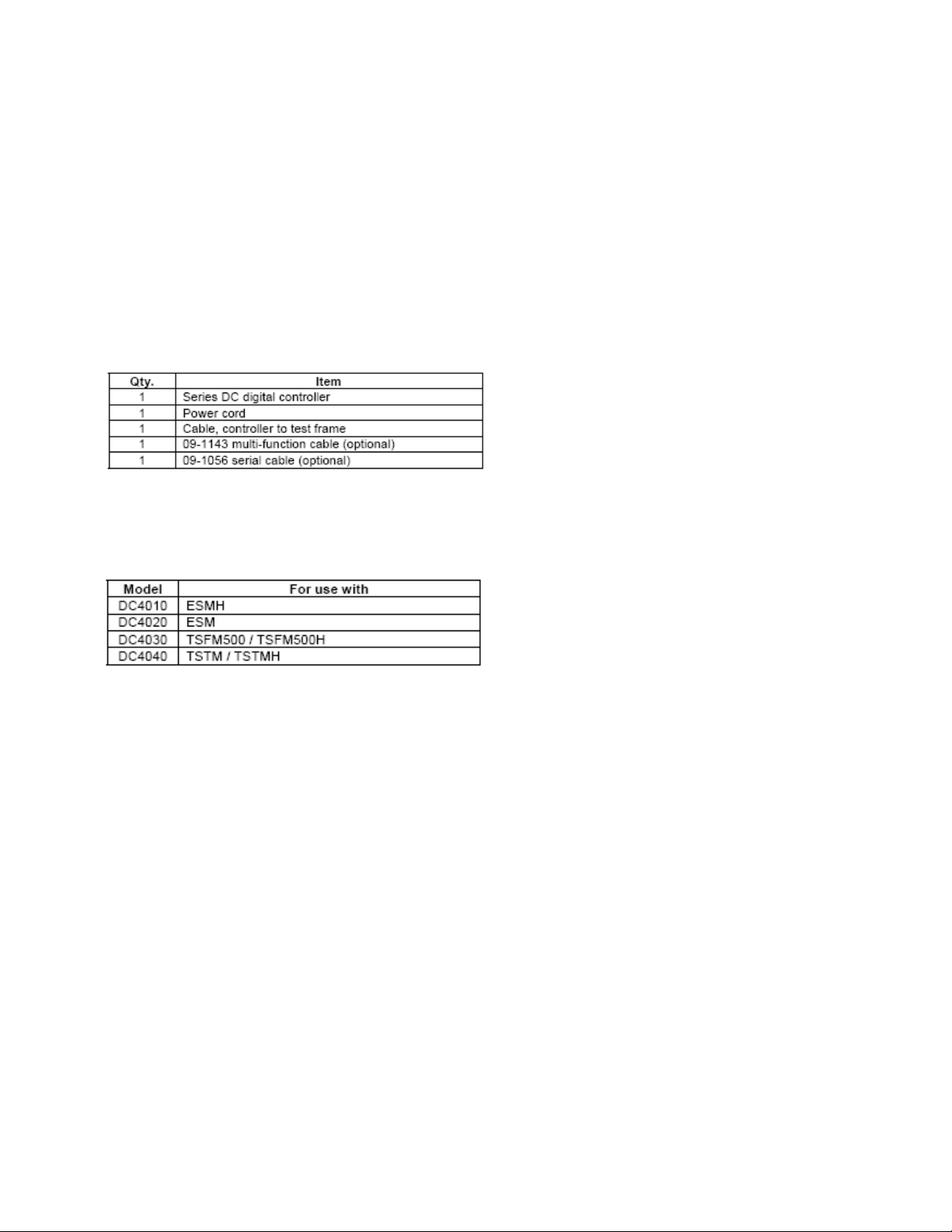
1 LIST OF INCLUDED ITEMS
2 OVERVIEW
There are several models within this series of digital controllers to accommodate different test stands, as follows:
Series DC controllers have two functional modes:
1. OPERATING MODE
This is the operating mode in which testing sequences can be started and stopped.
2. TEST PARAMETER SETUP
In this mode, test parameters are configured, such as rate of speed, number of cycles, password editing, and other
parameters.
3 MECHANICAL SETUP & SAFETY
3.1 Mounting
The controller should be placed on a clean, flat and level work area free from vibration. If desired, the controller can b e
secured to the work area with 1/4-20 screws fastened into the underside of the housing. The controller can also be
mounted using the ESM301-003 mounting kit. Screws of various lengths are supplied with this kit to accommodate a
range of bench thicknesses. Refer to the following illustration for proper assembly:
TSFM 500 DC 1 32-1101 REV 2 710
Page 4
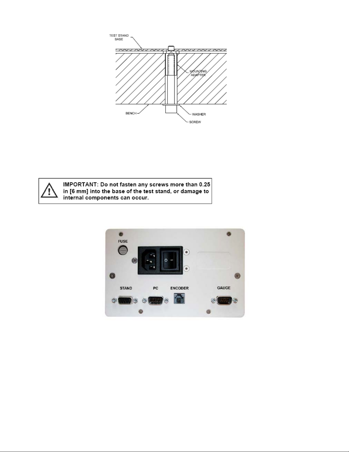
In general, the controller can be mounted at any angle, although extra care shou ld be taken during installation and
operation.
3.2 Setting up the Controller
The power plug and controller cable must be connected to the rear of the controller, as shown in the illustration below:
1. Fuse
2. STAND / Controller Cable Connector
Plug one end of the cable into this connector, and the other end into the connector adjacent to the motor on the test
stand. If this cable is not connected, the error message ENCODER ERROR will be shown on the display and the test
stand cannot be operated.
3. PC / PC Control Connector
Plug one end of the 09-1056 serial cable into this connector, and the other end into a serial connector on a computer.
4. Power Plug Receptacle
Plug the power cord in here.
5. ENCODER / Travel Indication Connector
TSFM 500 DC 2 32-1101 REV 2 710
Page 5
Applicable for TSTM / TSTMH test stands only
Plug one end of the RJ11 cable into this connector, and the other end into the connector on the underside of the
mechanism housing on the test stand.
6. GAUGE / Gauge Cable Connector
Plug one end of the 09-1143 cable into this connector, and the other end into a Series 5, Series BG or BGI gauge.
3.3 Connecting Power
Plug one end of the power cord into its receptacle at the rear of the controller and the other end into a wall outlet with
local earth ground (3-prong connector). Before turning on power, the following safety checks and procedures shoul d be
performed:
1. Never operate the controller if there is any visible damage to the power cord or the test stand. The controller
is powered by 110V/220V. Any contact with this high voltage can cause serious injury or even death.
2. Ensure that the controller is kept away from water or any other electrically conductive liquids at all times.
3. Make sure the electrical outlet powering the controller has local earth ground (3-prong connector).
4. The controller should be serviced by a trained technician only. Power must be disconnected before the
controller is opened. After the above safety checks and procedures have been performed, the controller may be
powered on and is ready for operation.
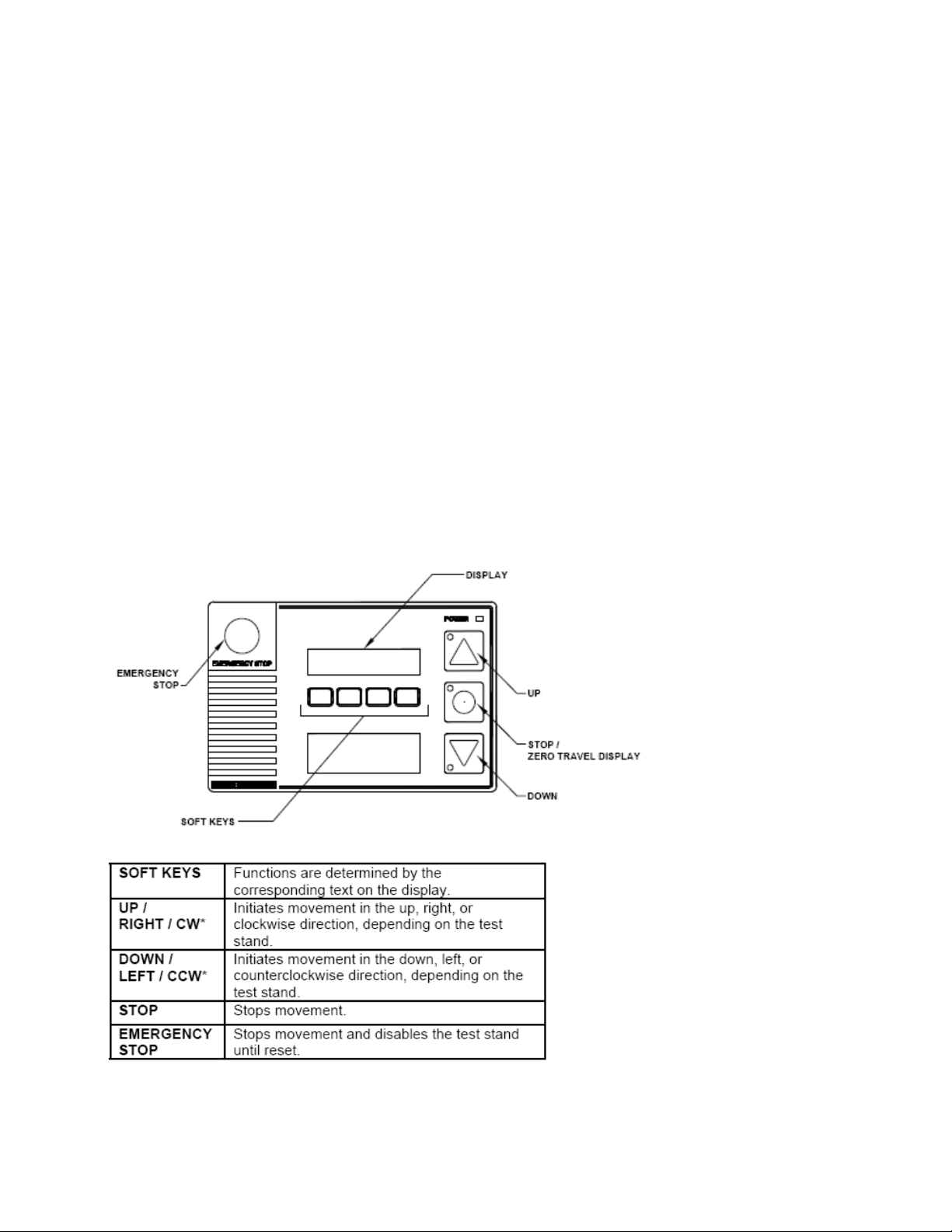
4 CONTROLS LAYOUT
* Although the direction of movement differs between test stands, this user’s guide will refer to the buttons as UP and
DOWN.
TSFM 500 DC 3 32-1101 REV 2 710
Page 6
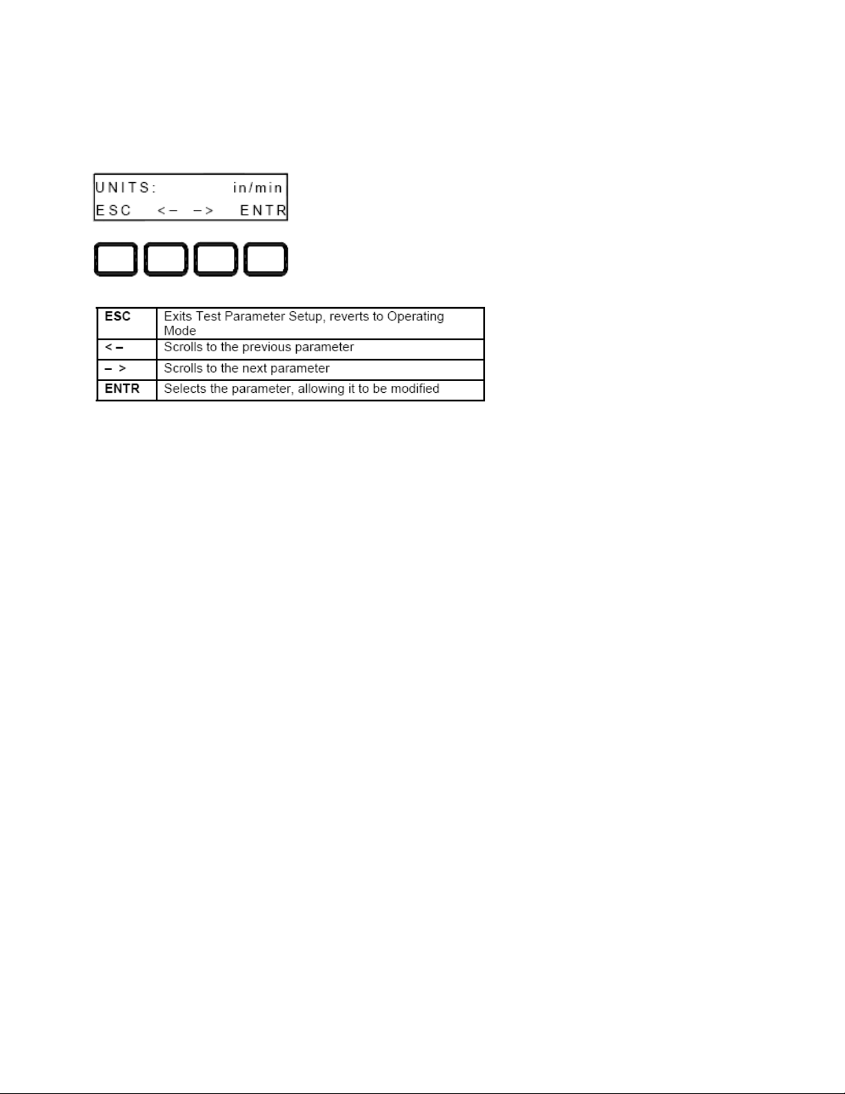
5 TEST PARAMETER SETUP
This section provides configuration instructions for each test parameter. The initial Test Parameter Setup screen appears
as follows:
When the parameters have been configured as desired and are ready to be saved, press ESC to exit Test Parameter
Setup. The screen will show SAVE CHANGES? Pressing YES will save the changes and the display will revert to current
status. Pressing NO will not save the changes and return to the Test Parameter Setup menu.
Note: Changes can be made to an unlimited number of settings before saving.
TSFM 500 DC 4 32-1101 REV 2 710
Page 7
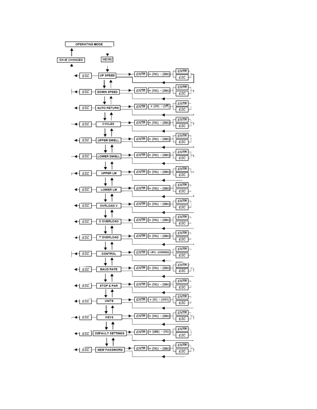
The following is a flow chart for the menu structure:
TSFM 500 DC 5 32-1101 REV 2 710
Page 8

5.1 Speed
Independent speeds can be set for both directions of movement. The parameters are labeled as follows:
Default speed settings and available speeds are as follows:
5.2 Auto Return (AUTO RETURN)
With this feature, the test stand moves to a limit switch, load set point, or travel limit (TSTM / TSTMH only), whichever
occurs first, and stops. Then, the test stand returns to the other limit and stops. The test speed is dictated by the
independent speed settings. The return speed is always maximum speed.
Default setting: off
Available settings: off, on
TSFM 500 DC 6 32-1101 REV 2 710
Page 9

5.3 Cycling (CYCLES)
This setting allows the user to configure the number of cycles through which the test stand will sequence. One cycle
consists of the test stand moving to a limit switch, load set point, or travel limit (TSTM / TSTMH only), whichever occurs
first, at the specified speed, stopping for the specified amount of dwell time, and returning to the other limit at the
specified speed.
Default setting: 00000 (off)
Available settings: 00000 – 99999
5.4 Dwell Time
This setting corresponds to the amount of time, in seconds, for which the test stand stops at the limit during a cycle
sequence. Independent dwell times can be set for both limits.
Note: the dwell time setting is unavailable for an auto return sequence.
Default setting: 0 (no dwell time)
Available settings: 0 – 9999.9
TSFM 500 DC 7 32-1101 REV 2 710
Page 10

5.5 CW and CCW Travel Limits (CW L and CCW L)
Applies to TSTM / TSTMH only
This setting corresponds to the rotational travel distance the test stand moves before stopping or cycling. CW and CCW
limits are programmed individually. The programmed distances are relative to the zero position of the test stand. The
travel indicator can be zeroed by pressing and holding STOP for three seconds.
Default setting: 1 revolution
Available settings: ± 2,777.77 revolutions
5.6 Overload Analog Output Voltage (OVRLOAD V)
This setting corresponds to the full scale analog voltage output of the force or torque gauge. Series DC controllers
protect gauges from overload by measuring incoming analog voltage and stopping test stand motion when the
programmed percentage of full scale has been reached (see Section 5.7). T he value for Mark-10 gauges is ±1V.
Adjustable voltage allows for compatibility with other brands as well.
TSFM 500 DC 8 32-1101 REV 2 710
Page 11

Default setting: OFF
Available settings: ±1V, ±2V, ±4V, OFF
5.7 Overload Settings (C OVERLOAD and T OVERLOAD or CW OLOAD and CCW OLOAD)
The setting corresponds to the percentage of full scale of the force or torque gauge at which test stand travel stops. For
example, a setting of 80% for a 50 lb capacity force gauge would stop test stand motion when 40 lb is reach ed.
Independent settings may be programmed for both load directions (tension and compression, or CW and CCW).
Note: For force test stands, when the crosshead is moving in the UP direction, only the tension overload setting applie s.
When the crosshead is moving in the DOWN direction, only the compression overload setting applies. The same concept
applies to the CW and CCW directions for torque test stands.
Default setting: 100%
Available settings: 20% - 100% (10% increments)
5.8 Control Source (CONTROL)
This setting corresponds to the source of test stand control. The default value CONSOLE sets the test stand to accept
commands only from the controller. Any external commands received through the serial port are ignored.
PC refers to external control via serial communication. If any parameters are changed on the front panel, these settings
will be ignored, except for Auto Return or Cycling. If either of these parameters are turned on, PC control will be turned
off.
Default setting: CONSOLE
Available settings: CONSOLE, PC
TSFM 500 DC 9 32-1101 REV 2 710
Page 12

5.9 Baud Rate (BAUD RATE)
This setting corresponds to the baud rate setting of the computer program controlling the test stand.
Default setting: 19200
Available settings:
1200, 2400, 4800, 9600, 19200, 38400, 57600, 115200
5.10 Stop Bits and Parity (STOP & PAR)
This setting corresponds to the stop bits and parity settings of the computer program controlling the test stand.
Default setting: 8-1n
Available settings:
8-1E 8 stop bits, 1 stop bit, even parity
8-1o 8 stop bits, 1 stop bit, odd parity
8-1n 8 data bits, 1 stop bit, no parity
8-2n 8 data bits, 2 stop bits, no parity
7-1E 7 data bits, 1 stop bit, even parity
7-1o 7 data bits, 1 stop bit, odd parity
7-2E 7 data bits, 2 stop bits, even parity
7-2o 7 data bits, 2 stop bits, odd parity
7-2n 7 data bits, 2 stop bits, no parity
TSFM 500 DC 10 32-1101 REV 2 710
Page 13

5.11 Units of Speed (UNITS)
Default setting: in/min or RPM
Available settings: in/min, mm/min or RPM, °/sec
5.12 Programmable Button Function (KEYS)
Three button function modes are available:
1. Maintained
The test stand will move continuously once the button has been pressed. Subsequently pressing the UP,
DOWN, or STOP during a test will stop motion.
2. Momentary
The test stand will move only if the button is held down. Releasing the button will stop movement immediatel y.
3. Auto
Holding down the button for more than 0.5 seconds will enter momentary mode, at which time an audi ble
indicator will sound and the LED indicator on the button pushed will be illuminated. A short tap on the button will
operate the test stand in maintained mode. Pressing UP, DOWN, or STOP during maintained mode will stop
motion.
Default setting: maintained
Available settings: maintained, momentary, auto
TSFM 500 DC 11 32-1101 REV 2 710
Page 14

5.13 Default Settings (DEFAULT?)
This setting provides a quick return to factory settings, as follows:
UP SPEED: Depends on test stand
DN SPEED: Depends on test stand
AUTO RETURN: off
CYCLING: 00000 (off)
CW L: 1 revolution
CCW L: 1 revolution
OVERLOAD V: OFF
OVERLOAD: 100%
CONTROL: CONSOLE
BAUD RATE: 19200
STOP & PAR: 8-1n
UNITS: Depends on test stand
PASSWORD: 0000 (off)
KEYS: maintained
Default setting: off
Available settings: off, on
5.14 Password (NEW PWORD)
If desired, a password can be set to prevent unwanted changes to test parameters. The password can be set to any
number between 0000 and 9999. The default setting of 0000 indicates that the password is disabled, and that the user
can freely enter the Test Parameter Setup menu. If misplaced or forgotten, the password may be reset. Contact Mark-10
for instructions.
Default setting: 0000 (off)
Available settings: 0000 – 9999
TSFM 500 DC 12 32-1101 REV 2 710
Page 15

6 OPERATING MODES
6.1 Mode Overview
Series DC controllers can be operated in three modes:
1. Basic Mode
Manual control of test stand movement.
2. Auto Return Mode
Test stand moves to a limit switch, load set point, or travel distance (TSTM / TSTMH only), whichever occurs
first, then reverses and moves at maximum speed to the other limit, whichever occurs first.
3. Cycling Mode
Test stand cycles between limits at the selected speed, and pauses at each limit for a selected period of time.
4. PC Mode
Test stand is controlled through a serial connection with a computer.
On the TSTM / TSTMH test stands, the screen appears as follows:
The item selected will be capitalized, as shown in the figure above. The set speed can be changed in Test Parameter
Setup. Independent speeds may be programmed for each direction.
TSFM 500 DC 13 32-1101 REV 2 710
Page 16

6.2 Menu Navigation
At power-up, the display will show the operation screen for whichever mode was used last. The display will appear as
one of the following:
Basic & Auto Return Modes:
Cycling Mode:
PC Mode:
Appears the same as in Basic and Auto Return modes.
Pressing menu will enter Test Parameter Setup. If a password has been programmed, the display will prompt the
following:
The password is a four digit number. The first digit in the password will be flashing, signifying that it is active and can be
incremented by pressing +. To advance to the next digit, press –>. Change subsequent digits in the same fashion. Once
the complete password has been entered, press ENTR. If correct, the display will enter Test Parameter Setup Mode. If
the password is incorrect, the words INCORRECT PASSWORD will flash, and the display will revert to Operating Mode.
6.3 Basic Mode
The test stand moves in the direction indicated by the UP and DOWN buttons. When the test stand is in motion, an LED
indicator on the button pushed will be illuminated. The KEYS setting controls how test stand movement responds to the
push of the UP and DOWN buttons. The three settings are:
1. Maintained (default)
The test stand will move continuously once the button has been pressed. Subsequently pressing STOP durin g a
test will stop motion.
2. Momentary
The test stand will move only if the button is pressed and held. Releasing the button will stop movement
immediately.
3. Auto
TSFM 500 DC 14 32-1101 REV 2 710
Page 17

Holding down the button for more than 0.5 seconds will enter Momentary mode, at which time an audible
indicator will sound and the LED indicator on the button pushed will be illuminated. A short tap on the button will
operate the test stand in Maintained mode. Pressing STOP during Maintained mode will stop motion.
To resume the test, press UP or DOWN again.
Pressing EMERGENCY STOP will immediately stop motion in any mode. To release, twist the button counterclockwise until it assumes its original position. To resume the test, press UP or DOWN.
The test stand will move until a limit switch, load set point, or travel distance set point (TSTM / TSTMH only) has been
reached. If the test stand has stopped at a load set point or travel distance set point, the limit condition may be
overridden by pressing and holding UP or DOWN for two seconds.
6.3.1 Travel Indication (TSTM / TSTMH only)
Travel indication is displayed in the upper left corner of the display, as shown in Section 6.1. The displayed units are the
same as configured in the UNITS parameter. Indicated travel is a relative value. To zero out travel distance, ensure that
the test stand is not in motion, then press and hold STOP for three seconds. If the cable connecting the angle encoder to
the rear of the controller is unplugged, the error message ENCODER ERROR will appear. To clear the message, insert
the cable, then press STOP.
6.3.2 Limit Switch Operation
Note: limit switches are standard on the ESMH test stand, and are optional on the ESM and TSFM500 / TSFM500H test
stands. Not applicable for TSTM / TSTMH test stands.
Limit switches allow the operator to set a location along the column at which point the crosshead will stop moving. Adjust
the switches’ positions by loosening, repositioning, and re-tightening the thumb scre ws.
Note: the distance between limit switches must be at least 0.2 in [5 mm].
6.3.3 Overload Protection
The 09-1143 cable is required for overload protection of a Mark-10 gauge. If overload protection is e na bled, the test
stand will stop when the programmed percentage of full scale of the gauge has been reached.
When overload protection is enabled, if the 09-1143 cable is disconnected, and/or if the force gauge is turned off, the
error message GAUGE ERROR will appear. Plug in the cable and/or turn on the force gauge to clear the message.
Note: For force test stands, when the crosshead is moving in the UP direction, only the tension overload setting applie s.
When the crosshead is moving in the DOWN direction, only the compression overload setting applies. The same concept
applies to the CW and CCW directions for torque test stands.
6.3.4 Auto Return Mode
With this setting, the test stand moves to a limit switch, load set point, or travel distance (TSTM / TSTMH only),
whichever occurs first, and stops. Then, the test stand returns at maximum speed to the other limit, whichever occurs
first, and stops. The speed at which the test stand travels is dictated by the independent speed settings.
The test stand can be stopped at any time during an Auto Return sequence by pressing STOP. To resume the test, press
UP or DOWN.
If the test stand has stopped at a load set point or travel distance set point, the limit condition may be overridden by
pressing and holding UP or DOWN for two seconds.
Travel indication and limit switch operation is the same as in Basic Mode
.
TSFM 500 DC 15 32-1101 REV 2 710
Page 18

6.4 Cycling Mode
This mode cycles the test stand between limit switches, load set points, or travel distance set points (TSTM / TSTMH
only), whichever occurs first. One cycle consists of the following steps:
1. Test stand moves to a limit at the specified speed.
2. Test stand stops for the specified amount of dwell time.
3. Test stand reverses direction, returns to the other limit at the specified speed, and stops.
A cycling sequence can be initiated from any position and can start in either direction. If the test stand is at a limit,
however, cycling can only be started in the direction of the other limit. To initiate a cycle sequence, press UP or DOWN.
During a cycle sequence, a counter will be displayed, indicating the number of cycles remaining, as shown below:
As in Basic Mode, the min, max, and set soft keys are active during crosshead movement. When the cycling sequence
has ended and the test stand has stopped at a load set point or travel distance set point, the limit condition may be
overridden by pressing and holding UP or DOWN for two seconds.
6.4.1 Dwell time
Dwell time is the amount of time, in seconds, for which the test stand stops at a limit during a cycle sequence. When the
test stand has reached a limit, a counter will be displayed, shown as follows:
If the DWELL U and/or DWELL L settings are set to 0, the test stand will immediately reverse direction upon reaching
the corresponding limit, and no counter will be displayed.
The cycle sequence may be interrupted before it has been completed by pressing STOP. A soft key labeled RESET will
appear as follows:
At this point, there are two options:
1. Canceling the cycle sequence:
Press RESET to stop and reset the cycle sequence. The cycle counter will revert to the number of cycles originally
programmed.
2. Resuming the cycle sequence:
Press UP or DOWN to resume.
TSFM 500 DC 16 32-1101 REV 2 710
Page 19

Once the sequence has been completed, the screen will revert to the number of cycles programmed originally. To begin
another cycle test, press UP or DOWN.
Travel indication and limit switch operation is the same as in Basic Mode.
6.5 PC Mode
The test stand may be controlled by a computer through the Series DC controller via serial communication. A list of
supported ASCII commands is provided below. All commands must be lowercase.
Note: Functions relating to distance measurement (indicated with an asterisk) are applicable only with the TSTM /
TSTMH stands.
a Request speed
b Set travel units to inches or revolutions
c Enter cycle mode
d Move down or CCW
e Set speed (ex. e10.00 = 10.00 in/min)
f Set cycles (ex. f0500 = 500 cycles)
g* Set lower travel limit (ex. g90.0 = 90 degrees)
h* Set upper travel limit (ex. h180.0 = 180 degrees)
i Set travel units to millimeters or degrees
j Set speed to maximum speed
k Set speed to minimum speed
l* Enter travel limit mode
m Enter manual mode
n* Transmit travel and torque readings
o Set speed to programmed speed
p** Request stand status**
q Request number of cycles completed
r Request number of cycles set
s Stop
t Reset cycle counter to zero
u Move up or CW
v* Request upper travel limit
w* Request lower travel limit
x* Request travel value
z* Reset travel to zero
*Applicable only to the TSTM / TSTMH test stands.
** The transmission of ASCII “p” will return the stand status.
The following are the return codes and their definitions.
Test stand status U = Moving up or CW
D = Moving down or CCW
S = Stopped
Operating mode C = cycle mode
L = limit mode
M = manual mode
Limit switch status UL = crosshead at upper limit
DL = crosshead at lower limit
Commands relating to Mark-10 force and torque gauges are NOT the same as indicated in the respective user’s guides.
A list of supported ASCII commands is provided below. All commands must be uppercase:
A Displays current unit
F Toggles between Normal and Data Collect modes
P Steps through Normal mode, Tension/CCW Peak mode, and Compression/CW Peak mode
R Zeroes the gauge (zeroes all modes)
S Sends currently selected mod e (Normal, Tension/CCW Peak, Compression/CW Peak, or Data Collect)
U Steps through units
X or ? Sends currently displayed reading
Y Enables RS-232 output and sends continuous data stream when in Data Collect mode
Z Zeroes the currently selected mode
TSFM 500 DC 17 32-1101 REV 2 710
Page 20

The 09-1143 cable is needed to communicate between a Mark-10 gauge and the co ntroller.
The 09-1056 serial cable is needed to communicate between a computer and the controller. Baud rate, stop bits and
parity must be programmed in the stand to correspond with the computer program’s settings. Details on this are provided
in Section 5.
While in PC control, if any parameters are changed on the controller, these settings will be ignored, except if Auto Return
or Cycling are turned on. If so, PC control will be turned off automatically.
7 COMMUNICATING WITH MESURGAUGE
Series DC controllers can communicate with MESURgauge data collecti on software. The test stand can output either
load data only or load data combined with travel data. To communicate with MESURgauge, certain settings in the test
stand, gauge, and software must be changed as follows:
7.1 Load data only
1. Check physical connections (refer to Section 3.2).
2. Gauge settings (refer to the gauge’s user’s guide).
1. Set to automatic output of every sample.
2. Disable Mitutoyo BCD output.
3. Test stand settings
1. Set the baud rate to 115,200.
2. Set the Control mode to Console.
7.2 Load and travel data simultaneously (TSTM / TSTMH only)
1. Check physical connections (refer to Section 3.2)
2. MESURgauge settings
1. Test Setup tab
1. Under Travel check the Enable box. Under Reading Mode, if Continuous Readings is selected,
Readings perSec. defaults to 4. This value can be increased.
2. Port Configuration tab
1. Identify a working com port, and select the appropriate port in Gauge Port Settings.
2. Under Gauge Port Settings, change baud rate to 115,200.
3. Under Reading Request String change String to Write to “n” (lowercase, no quotes). Uncheck the
CR box.
4. Check the box labeled Travel Data Combined with Load Data. No changes are needed to the default
lines, fields, and delimiter.
5. Click APPLY after making any changes in the Gauge Port Settings area.
3. Gauge settings (refer to the gauge’s user’s guide)
1. Set to automatic output of every sample.
2. Disable Mitutoyo BCD output.
4. Test stand settings
1. Set the baud rate to 115,200.
2. Set the Control mode to Console.
5. The Gauge Settings tab and all other gauge-related functions cannot be used while MESURgauge is
connected to the DC controller. It is intended for use only when connected to a Mark-10 gauge directly.
8 SPECIFICATIONS
TSFM 500 DC 18 32-1101 REV 2 710
Page 21

9 DIMENSIONS
in [mm]
10 WARRANTY
Limited Warranty on Products
Any Cooper Instruments product which, under normal operating conditions, proves defective in material or in
workmanship within one year of the date of shipment by Cooper will be repaired or replaced free of charge
provided that a return material authorization is obtained from Cooper and the defective product is sent,
transportation charges prepaid, with notice of the defect, and it is established that the product has been
properly installed, maintained, and operated within the limits of rated and normal usage. Replacement or
repaired product will be shipped F.O.B. from our plant. The terms of this warranty do not extend to any
product or part thereof which, under normal usage, has an inherently shorter useful life than one year. The
replacement warranty detailed here is the buyer’s exclusive remedy, and will satisfy all obligations of Cooper
whether based on contract, negligence, or otherwise. Cooper is n ot responsible for any incidental or
consequential loss or damage which might result from a failure of any and all other warranties, express or
implied, including implied warranty of merchantability or fitness for particular purpose. Any unauthorized
disassembly or attempt to repair voids this warranty.
Obtaining Service under Warranty
Advance authorization is required prior to the return to Cooper Instruments. Before returning the item,
contact the Repair Department c/o Cooper Instruments at (540) 349-4746 for a Return Material Authorization
number. Shipment to Cooper shall be at buyer’s expense and repaired or replacement items will be shipped
F.O.B. from our plant in Warrenton, Virginia. Non-verified problems or defects may be subject to a $150
evaluation charge. Please return the original calibration data with the unit.
Repair Warranty
All repairs of Cooper products are warranted for a period of 90 days from date of shipment. This warranty
applies only to those items that were found defective and repaired; it does not apply to products in which no
defect was found and returned as is or merely recalibrated. It may be possible for out-of-warranty products
to be returned to the exact original specifications or dimensions.
TSFM 500 DC 19 32-1101 REV 2 710
Page 22

* Technical description of the defect: In order to properly repair a product, it is absolutely necessary for
Cooper to receive information specifying the reason the product is being returned. Specific test data, written
observations on the failure and the specific corrective action you require are needed.
TSFM 500 DC 20 32-1101 REV 2 710
 Loading...