

Page 1
DCM 460 VOLTAGE BRIDGE AMPLIFIER
Description
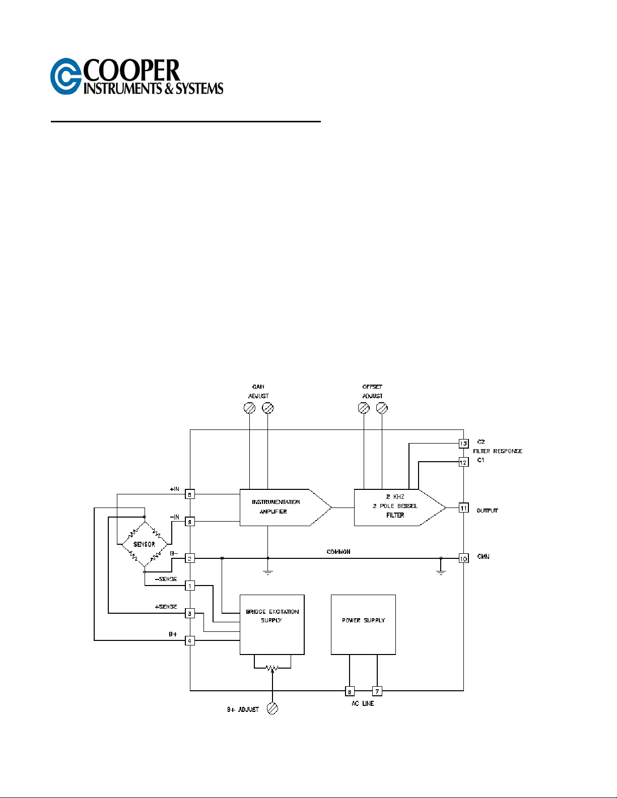
The DCM 460 Bridgesensor is a self-contained, AC powered, signal conditioning module for bridge type
instrumentation. It contains a precision differential instrumentation amplifier with filtered output and a highly
regulated, low noise, adjustable output bridge excitation source. The unit is completely encapsulated for use in
rugged environments. The output filter cutoff frequency is 2000Hz and may be lowered by adding two external
capacitors.
Features
• 2 kHz Frequency Response
• Rugged, Compact And Fully Encapsulated
• Complete System-just Add AC Power
• Ready To Use With Screwdriver Wiring
• Stable and Accurate
Applications
• Weighing With Load Cells
• Long Term Structural Monitoring
• Process Control Pressure Transducers
• Temperature Controls Using Thermocouples
• Strain Measurements
Figure 1. Simplified Block Diagram
CF 28 1 4/2001
Page 2

Specifications
(Typical @ 25°C unless noted)
Amplifier
Gain Range 40-250
Gain Temperature Coefficient 200 ppm/°C
Drift (RTI) 3 µV/°C
Input Bias Current ±30 nA
Input Impedance
Differential
Common Mode
Output Noise (RTO)
At gain=100
1 Hz to 2 kHz
Input Noise
Line Frequencies
Output Offset-Tare
Range
Drift
Common Mode Rejection
Gain=40 (DC-60 Hz)
Gain=250 (DC-60 Hz)
Rated Output (2k load) ±10V
Output Impedance
DC to 2 kHz
Dynamic Response
DC to –3 dB two pole
Bessel Filter
Common Mode Input Voltage ±6.5V
Bridge Supply
Input 115 VAC ±10% 50 to 60 Hz
Output Voltage 4 to 15 Volts
Output Current 120 mA
(see output voltage vs. current curve)
Load & Line Regulation 0.05%
VOUT=12V, IL=0 to 100 mA
Output Noise 0.5 mV RMS
Drift 200 ppm/°C max.
B+ Potentiometer Hysteresis 0.3% of output max.
Short Circuit Current 750 mA
Line Isolation 1,500 VDC
Mechanical
Operating Temperature 0°C to 70°C
Storage Temperature -25°C to +85°C
Weight 18 oz. (510 grams)
Size 3.75”L x 2.0”W x 2.87”H
3,000 megohms
6 megohms
2 mV P-P
15 µV P-P
-5V to +2V
±0.2 mV/°C
90 dB
100 dB
0.01 ohms to 1 ohm
2 kHz
(100, 220 & 230 VAC available)
9.53 x 5.1 x 7.62 (cm)
Getting Started with the DCM 460
I. Hook Up Procedure
A. Connect the +out of your load cell to the +INPUT, pin 8.
B. Connect the -out of your load cell to the -INPUT, pin 9.
Note: If the ± SENSE are not used in your load cell application, the connections in step C & D need to be
followed. If the ±SENSE are going to be used, do not jumper them as described in steps C & D.
C. Connect B+, pin 4, to the + excitation of your load cell and jumper the + SENSE, pin 3, to B+, pin 4.
D. Connect B-, pin 2, to the -excitation of your load cell and jumper the - SENSE, pin 1, to B -, pin 2.
E. Connect the VAC power supply to the AC input lines, pins 6 and 7.
II. Turn On Procedure
A. Verify that the hook up procedure is complete.
B. Verify the correct AC voltage is applied to the DCM 460; i.e. 100, 115, 220, 230.
CF 28 2 4/2001
Page 3

C. Turn on the AC source supply to the DCM 460.
D. Set the required EXCITATION supply voltage to the load cell by adjusting B+ ADJUST.
III. Calibration Procedure for Zero Voltage Adjustment
A. Jumper the + and - input terminals, pins 8 and 9, together.
B. Connect a voltmeter across the output, pins 11 and 10.
C. Adjust the COARSE OFFSET and the FINE OFFSET potentiometers for the desired ZERO voltage.
IV. Full Scale Voltage Adjustment
A. Remove the jumper between the + and - input terminals and apply a known load to your load cell, in
most cases it would be 100% of full scale.
B. Adjust the COARSE GAIN and FINE GAIN potentiometers for the desired FULL SCALE output.
C. Calibration is now complete. However, the user should recheck the ZERO & FULL SCALE voltage
output before continuing.
Figure 2. Safe Operating Curve
Figure 3. Typical Bridge Application
Transducer Excitation
Transducer bridge excitation is provided by an AC line powered, adjustable, well regulated, low noise power supply.
The excitation voltage is adjustable by means of a molded-in potentiometer which allows the output voltage to be
varied from 4 to 15 Volts. The output ripple is extremely low and the line and load regulation are 0.05%.
CF 28 3 4/2001
Page 4

The sense lines minimize variations in output voltage with changes in load current or lead resistance. It should be
noted that if the sense feature is not being used, terminal 1 must be connected to terminal 2. Terminals 3 and 4
must be connected also. The supply will provide up to 120 mA of output current. These features make the unit ideal
for most common strain gage bridge circuits of 120, 350, and 500 Ohms.
The supply has short circuit protection to protect it against short-term faults. The output recovers automatically from
short circuit conditions once the short is removed.
Safe Operating in the Unsafe Area
The curve (Figure 2) describes the region of safe operating output current at each voltage setting level. If excitation
is desired at the 4 Volt level with 120mA, this can be accomplished by using a resistor of at least 2 watts in size in
series with the bridge. The right value resistor would drop 11 Volts allowing 4 Volts at 120mA across the bridge
while minimizing internal heating of the DCM 460. The + sense line would regulate the supply to the required 4
Volts. Normal operation of single bridges at 10 Volts and under 100mA (all 125, 350, and 500 Ohm bridges) can be
accomplished within the safe operating area.
Instrumentation Amplifier
The built-in amplifier is a true differential input, low noise, low drift, instrumentation amplifier. It has a high common
mode rejection ratio (CMRR) and is provided with an output offset that is potentiometer adjustable. The minimum
gain setting of the amplifier is 40 and the maximum gain is 250. The amplifier can withstand input voltages up to 15
Volts without damage. The output of the amplifier is filtered to be 3dB down at 2kHz using a double pole Bessel
response filter. The output of the amplifier is 10 Volts at 5mA making it compatible with modern data acquisition
techniques and systems. Capacitors may be added to terminals 10, 11, 12, and 13 to lower the filter cutoff
frequency. This will reduce the DCM 460 output noise and system noise where the high frequency response is not
required.
Typical Bridge Application
Figure 3 shows a typical bridge application using a standard 350-Ohm bridge. This could be a strain gage, load cell,
pressure transducer, accelerometer, or other bridge based measurement.
Typical bridge output is 2 or 3 mV/Volt of excitation. With the power supply excitation voltage at 10 Volts an output
of 20 to 30 mV from the bridge can be obtained. The common mode voltage of the bridge (the instrumentation
amplifier input signal level) is 5 Volts. This is well within the 6.5 Volt common mode voltage range of the amplifier.
The built-in potentiometer set to a gain of 200 would achieve an output voltage of 4 to 6 Volts.
Assuming a standard 350-Ohm bridge is used, the current required from the excitation supply (set at 10 Volts)
would be 28.6mA. If the leads were long enough to have 10 Ohms of internal resistance there would be a drop of
over 0.286 Volts in both the plus and common side of the bridge. To eliminate this potential error (especially where
the current might vary during the course of a measurement) the sense lines are connected to measure and regulate
the voltage right at the bridge rather than at the output of the supply. The decision to use the sense leads or not
depends entirely on the lead length, its resistance, and the effect of that error on the measurement.
Application Suggestions
The DCM 460 is designed to eliminate many of the ordinary problems associated with bridge type measurements.
Since the whole system is in one case the common problem of ground loops or circulating currents caused by poor
wiring practices is eliminated. It is recommended that lead lengths be kept to a minimum. The use of shielded
twisted pairs for the input leads is recommended for most applications.
To minimize self-heating errors the use of minimum excitation power is suggested as is sufficient heatsinking of the
transducer whenever possible. For optimum stability a one-hour warm-up is recommended. Avoid large
temperature changes or stray magnetic fields.
The DCM 460 Bridgesensor is ready to wire into your system, have power applied, and start making measurements
for you.
CF 28 4 4/2001
Page 5

Filter Roll Off Frequency
The table in Figure 4 shows the values for C1 and C2 to set the 3 dB filter frequency. A printed circuit board is
included for convenient mounting of the two capacitors. Use X7R ceramic or foil type capacitors.
Filter
Frequency
C1
To Pin 11
C2
To Pin 10
2000 Hertz None None
200 Hertz 0.068 μF 0.022 μF
20 Hertz 0.68 μF 0.22 μF
9.4 Hertz 1.5 μF 0.47 μF
Figure 4. Filter Roll Off Frequency
Mechanical Specifications
Specifically designed for rugged field use the DCM 460 is completely encapsulated in epoxy using a vacuum
potting system to insure a complete seal against corrosive environments. It is similarly protected against shock and
vibration and will provide years of reliable and accurate operation.
CF 28 5 4/2001
Page 6

Figure 5. Case Dimension
Terminal Strip Assignments
Screw
Terminal
1 SENSE 8 +INPUT
2 B- 9 -INPUT
3 +SENSE 10 AMPLIFIER CMN
4 B+ 11 AMPLIFIER OUTPUT
5 NOT USED 12 FILTER-C1
6 AC 13 FILTER-C2
7 AC
Function
Screw
Terminal
Function
W ARRANTY REPAIR POLICY
Limited Warranty on Products
Any Cooper Instruments product which, under normal operating conditions, proves defective in material or in workmanship
within one year of the date of shipment by Cooper will be repaired or replaced free of charge provided that a return
material authorization is obtained from Cooper and the defective product is sent, transportation charges prepaid, with
notice of the defect, and it is established that the product has been properly installed, maintained, and operated within the
limits of rated and normal usage. Replacement or repaired product will be shipped F.O.B. from our plant. The terms of
this warranty do not extend to any product or part thereof which, under normal usage, has an inherently shorter useful life
than one year. The replacement warranty detailed here is the buyer’s exclusive remedy, and will satisfy all obligations of
Cooper whether based on contract, negligence, or otherwise. Cooper is not responsible for any incidental or
consequential loss or damage which might result from a failure of any and all other warranties, express or implied,
including implied warranty of merchantability or fitness for particular purpose. Any unauthorized disassembly or attempt to
repair voids this warranty.
Obtaining Service under Warranty
Advance authorization is required prior to the return to Cooper Instruments. Before returning the item, contact the Repair
Department c/o Cooper Instruments at (540) 349-4746 for a Return Material Authorization number. Shipment to Cooper
shall be at buyer’s expense and repaired or replacement items will be shipped F.O.B. from our plant in Warrenton,
Virginia. Non-verified problems or defects may be subject to a $100 evaluation charge. Please return the original
calibration data with the unit.
Repair Warranty
All repairs of Cooper products are warranted for a period of 90 days from date of shipment. This warranty applies only to
those items that were found defective and repaired; it does not apply to products in which no defect was found and
returned as is or merely recalibrated. It may be possible for out-of-warranty products to be returned to the exact original
specifications or dimensions.
*Technical description of the defect: In order to properly repair a product, it is absolutely necessary for Cooper to receive
information specifying the reason the product is being returned. Specific test data, written observations on the failure and
the specific corrective action you require are needed.
CF 28 6 4/2001
 Loading...