

Page 1

DCM 437
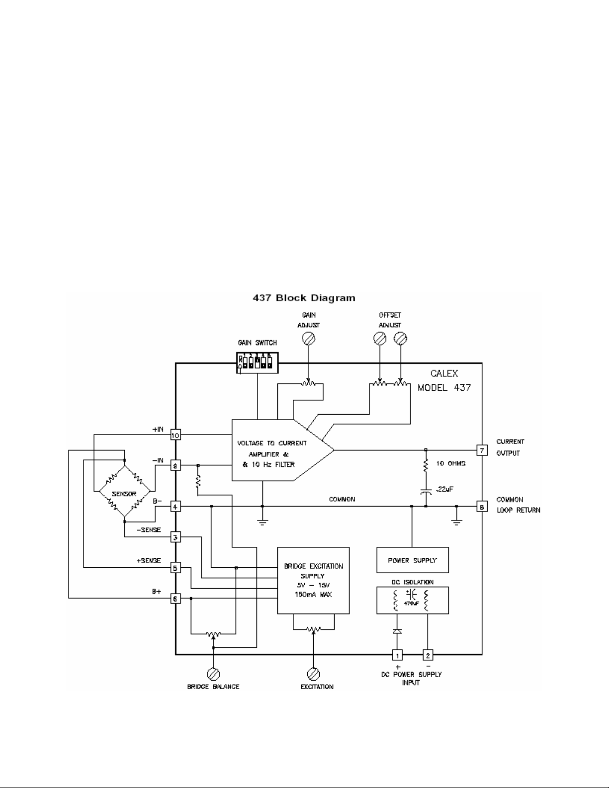
CURRENT BRIDGE AMPLIFIER
USER’S GUIDE
www.cooperinstruments.com
PH: 540-349-4746 • FAX: 540-347-4755
Page 2
Features
• Complete Strain Gage Bridge Signal Conditioner
• 4-20 mA or 0-20 mA Output
• Output Capable of Driving 1000 ohm Loop
• Bridge Balance with 68% Tare Offset Capability
• High Gain Amplifier; Can Accept Live Load Signals as Low as 3 mV and Provide 16 mA Output Span
• Sufficient Excitation Current for Five Load Cells
• Powered by 10 to 36 VDC Unregulated
• Rugged Epoxy Encapsulated Design
Applications
• Weighing with Load Cells
• Process Control Add-on Loops
Description
The Model DCM 437 is a self-contained, DC powered signal conditioner for bridge type instrumentation. It contains
a precision differential amplifier with filtered output and a highly regulated, low noise, adjustable output bridge
excitation source. What sets the DCM 437 apart is a Bridge Balance pot and high gain capability to accurately
condition load cell weighing systems with large tare offsets and small live load signals. The unit is completely
encapsulated for use in rugged environments.
CF 27 2 4/2001
Page 3

Specifications
Output Current Span
Input for 16 mA Span
Zero Adjust
Temperature Coefficient
0° to 55°C
Hysteresis 50 microamp maximum
Amplifier
Cell Sensitivity
(10 Volts Excitation)
Linearity 0.005% typical
Temperature Stability 50 ppm/°C
Hysteresis 0.1% of span maximum
Input Bias Current 150 pA maximum
Input Noise: DC to 10 Hz 4 microvolts P-P maximum
Common Mode Input 0 to +7.5 Volts
Common Mode Rejection
DC to 60 Hz
Output
Current 0 to 20 mA
Loop Resistance 0 to 1000 ohm
Compliance 20 Volts maximum
Frequency Response 10 Hertz, 2 Pole Filter
Response Time to 0.1% 90 ms typical
Bridge Excitation Supply
Adjustment Range 5 to 15 Volts
Load Current 150 mA maximum
Stability 100 ppm/°C maximum
Hysteresis 0.1%
Bridge Balance Adjust- (Tare Weight)
With 350 Load Cell
3mV/V Sensitivity
Power Requirements
Input power supply is DC isolated from the amplifier and is reverse polarity protected.
Input Voltage 10 to 36 Volts DC
Input Current
with 150mA B+ load
with one 350 ohm Bridge
120 Hertz Ripple allowed
on input supply
Isolation 700 Volts DC & .0033 mF
NOTE: Specifications apply 0°C to 55°C and 10 to 36 Volts DC input.
Getting Started with the Model DCM 437
This procedure is for large tare weights, i.e. greater than about 10% of the cell’s full scale rating.
I. Hook Up Procedure
A. Connect the + out of your load cell to the + INPUT, pin 10.
B. Connect the - out of your load cell to the - INPUT, pin 9.
Note: If the ±SENSE are not used in your application, the connections in step C & D need to be followed. If the
± SENSE are going to be used, do not jumper them as described in steps C & D.
C. Connect +Excitation, pin 6, to the + excitation of your load cell and jumper the + SENSE, pin 5, to
+Excitation, pin 6.
D. Connect -Excitation, pin 4, to the - excitation of your load cell and jumper the - SENSE, pin 3, to -Excitation,
pin 4.
4 to 20 mA; 0 to 20 mA
3 mV to 62 mV
12 mA
1 microamp/°C typical
4 microamp/°C maximum
0.3 mV/V to 6.2 mV/V
90 dB minimum
± 68% of Full Scale
0.17A @ 36V to 0.7A @10V
0.1A @ 36V to 0.35A @10V
1 Volt P-P at 10 Volts input
2 Volts above 12 Volts input
CF 27 3 4/2001
Page 4

E. Determine the voltage of the power supply to be used and adjust within the 10 to 36 volt range if necessary
before connecting to the power pins, 1 and 2.
F. Verify that the hook up procedure is complete.
G. Turn on the power supply and check the bridge excitation supply.
II. Calibration Procedure
A. Set the GAIN SWITCH position 1 ON and all others OFF.
B. Short the signal input pins 9 and 10 together with a clip lead. Adjust the COARSE and FINE OFFSET pots,
C and B, for zero or 4 mA output current.
Note: Some PLC models do not accept negative inputs. The maximum negative current is 1 mA.
C. Remove the short between the signal input pins, 9 and 10. Adjust the BRIDGE BALANCE pot for zero or 4
mA output current.
D. Set the GAIN SWITCH to the expected load cell output.
E. Adjust the BRIDGE BALANCE pot for zero or 4 mA output current.
F. Apply the live load to the cell and adjust the GAIN, pot D, for the desired output current.
G. Remove live load and use the COARSE and FINE OFFSET pots to set the zero or 4 mA output current.
H. Repeat steps E. to G. until the desired settings are obtained.
Amplifier
The built-in amplifier is a true differential input, low noise, low drift, instrumentation amplifier. It has a high common
mode rejection ratio (CMRR) and is provided with an output offset that is potentiometer adjustable. The output
offset pots adjust the output zero current up to 12 mA. The zero current can also be adjusted for 0 to 20 mA output.
The instrumentation amplifier has a gain DIP switch which changes the gain by factors of two and a gain
potentiometer for fine adjustments.
The amplifier accepts input signals of 3 mV to 62 mV. The amplifier can withstand input voltages up to 15 Volts
without damage. The output of the amplifier is filtered to be 3 dB down at 10 Hz using a double pole Butterworth
filter to minimize the effects of high frequency electrical and physical noise on the system.
The DCM 437 has a Bridge Balance pot, which is connected internally to the amplifier - INPUT.
Transducer Excitation
Transducer excitation is provided by an adjustable, well-regulated, low noise power supply. The excitation voltage
is adjustable by means of a molded-in potentiometer, which allows the output voltage to be varied from 5 to 15
Volts. It is capable of supplying up to 150 mA to easily drive five 350-ohm load cells at 10 Volts.
The +Excitation supply has remote sensing provisions for 6 wire configurations. The sense lines minimize variations
in output voltage with changes in load current or lead resistance. The supply output, +Excitation, may be connected
through a 300-ohm safety barrier and the sense lines will regulate the voltage across a 350-ohm bridge between 5
and 8 volts.
The supply has short circuit protection to protect it against short-term faults. The output recovers automatically from
short circuit conditions once the short is removed.
CF 27 4 4/2001
Page 5

Bridge Balance
The Bridge Balance pot provides up to 68% of full-scale tare weight adjustment when using a 350-ohm, 3mV/V load
cell. The DCM 437 can then be adjusted to provide full span output with only about 10% of the cell’s range.
DCM 437 Gain Switch
Bridge Output Signal for:
Mechanical Specifications
Gain Switch
Position “ON”:
1
2
3
4
5
0 to 20 mA 4 to 20 mA
50mV to 62.5mV 40mV to 50mV
25mV to 50 mV 20mV to 40mV
12.5mV to 25mV 10mV to 20mV
6.25mV to 12.5mV 5mV to 10mV
3.125mV to 6.25mV 2.5mV to 5mV
CF 27 5 4/2001
Page 6

Terminal Strip Assignments
Screw
Terminal
1
2
3
4
5
Function
+DC POWER
- DC POWER
-SENSE
-EXCITATION
+SENSE
Screw
Terminal
6
7
8
9
10
Function
+EXCITION
CURRENT OUTPUT
AMPLIFIER CMN
-INPUT
+INPUT
WARRANTY REPAIR POLICY
Limited Warranty on Products
Any Cooper Instruments product which, under normal operating conditions, proves defective in material or in workmanship
within one year of the date of shipment by Cooper will be repaired or replaced free of charge provided that a return
material authorization is obtained from Cooper and the defective product is sent, transportation charges prepaid, with
notice of the defect, and it is established that the product has been properly installed, maintained, and operated within the
limits of rated and normal usage. Replacement or repaired product will be shipped F.O.B. from our plant. The terms of
this warranty do not extend to any product or part thereof which, under normal usage, has an inherently shorter useful life
than one year. The replacement warranty detailed here is the buyer’s exclusive remedy, and will satisfy all obligations of
Cooper whether based on contract, negligence, or otherwise. Cooper is not responsible for any incidental or
consequential loss or damage which might result from a failure of any and all other warranties, express or implied,
including implied warranty of merchantability or fitness for particular purpose. Any unauthorized disassembly or attempt to
repair voids this warranty.
Obtaining Service under Warranty
Advance authorization is required prior to the return to Cooper Instruments. Before returning the item, contact the Repair
Department c/o Cooper Instruments at (540) 349-4746 for a Return Material Authorization number. Shipment to Cooper
shall be at buyer’s expense and repaired or replacement items will be shipped F.O.B. from our plant in Warrenton,
Virginia. Non-verified problems or defects may be subject to a $100 evaluation charge. Please return the original
calibration data with the unit.
Repair Warranty
All repairs of Cooper products are warranted for a period of 90 days from date of shipment. This warranty applies only to
those items that were found defective and repaired; it does not apply to products in which no defect was found and
returned as is or merely recalibrated. It may be possible for out-of-warranty products to be returned to the exact original
specifications or dimensions.
*Technical description of the defect: In order to properly repair a product, it is absolutely necessary for Cooper to receive
information specifying the reason the product is being returned. Specific test data, written observations on the failure and
the specific corrective action you require are needed.
CF 27 6 4/2001
 Loading...