

Page 1
DCI 120
20Hz Bridge/Strain Recorder
DCI 120-10
10mV, 20 Hz, Bridge Recorder
DCI 120-25
25mV, 20 Hz, Bridge Recorder
DCI 120-100
100mV, 20 Hz, Bridge Recorder
DCI 120-1000
1000mV, 20 Hz, Bridge Recorder
Configuring the Data Logger
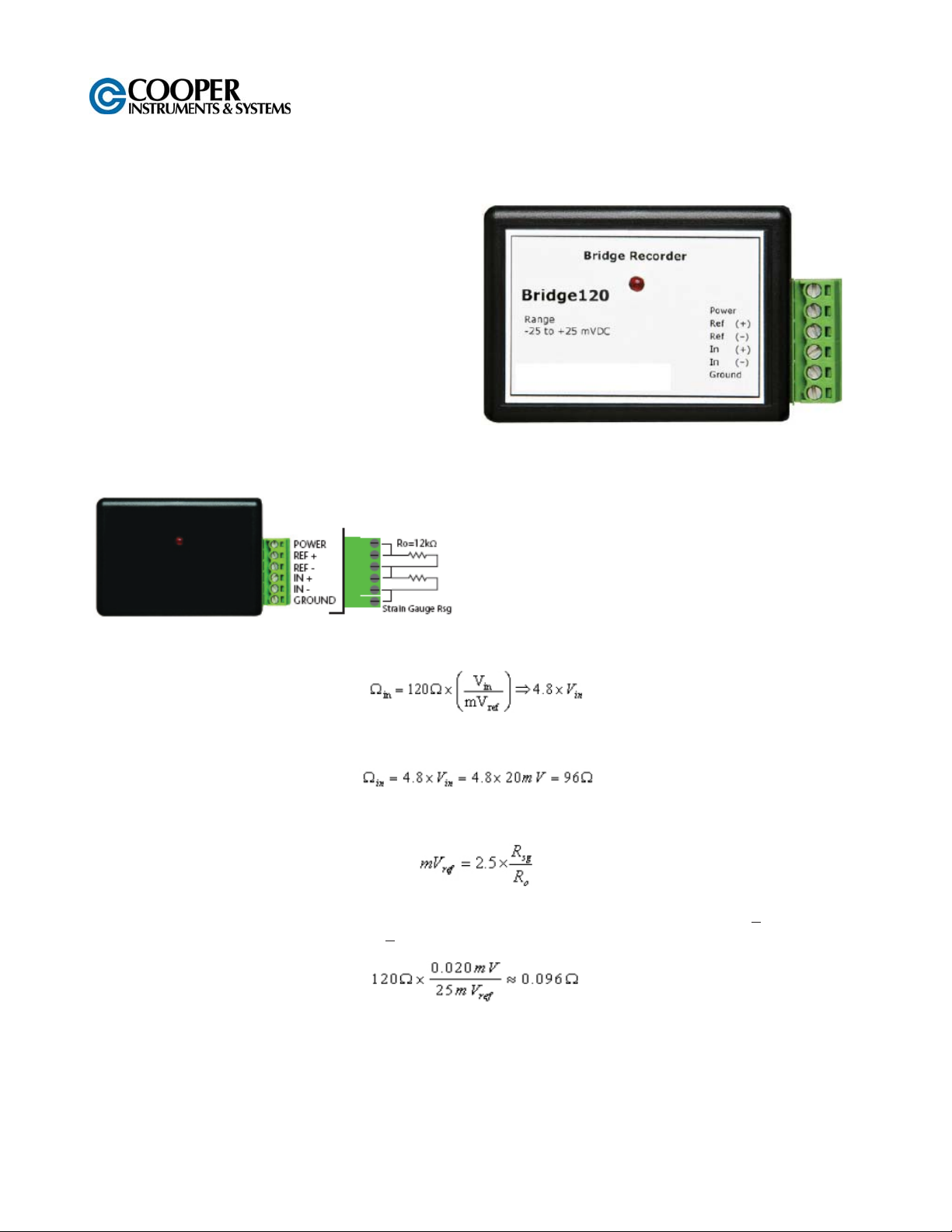
Voltage Divider Configuration
The Voltage Divider configuration is a simple and frequently used setup to measure bridge strain.
1. Jumper between POWER and REF+
2. Place a 12kΩ resistor between REF+ and REF-
3. Jumper between REF- and IN+
4. Place the strain gage between IN+ and IN-
5. Jumper between IN- and GROUND
Conversions
To convert the Voltage values into Ohms, use the following formula:
Example: The software reports a voltage of 20mV in the circuit described above. The strain gage resistance is
therefore:
The resistor Ro between REF+ and REF- and the strain gage value form the mV reference (mVref). This may
be expressed as:
The Bridge120-25 has a resolution of about 2μV. If the resistance of the strain gage changes by +.1, the device
would measure a change of approximately +
approximately:
Note: The maximum voltage must be kept within the specified input range. See data sheet for details.
20μV. Conversely, this voltage resolution translates in Ohms to
Product Notes
LEDs
Once started, the LED will flash at the selected reading rate to indicate that the device is running.
CF 179 1 Rev A 2008.07.08
Page 2
Installation Guide
Installing the Interface cable
- IFC200, IFC202 or IFC300; Refer to the “Quick Start Guide” included in the package.
- IFC110, IFC102 or IFC103; Plug the serial cable into the port and verify it is secure.
- USB-1 or USB-101; Install the USB drivers from the CD provided in the kit, than plug the USB cable into the
computer and the serial cable into the serial port.
Installing the software
Insert the Software CD in the CD-ROM Drive. If the autorun does not appear, locate the drive on the computer
and double click on Autorun.exe. Follow the instructions provided in the Wizard.
Connecting the data logger
- Once the software is installed and running, plug the interface cable into the data logger.
- Click the Communication Menu, then Auto Configure Port.
- After a moment, a box similar to the following will appear;
- Click OK. The Device Status box will appear. Click OK.
- At this point, communications have been configured for your logger. These settings can be found under the
Communication Menu.
Note: For additional installation instructions refer to your “Data Logger & Software Operating Manual”.
Device Operation
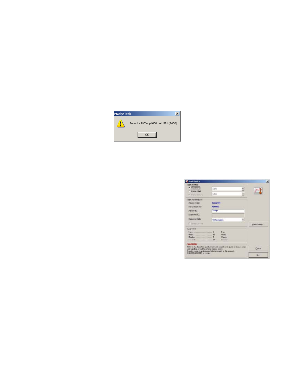
Starting the data logger
- Click Device Menu then Start Device.
- Choose the desired start method.
- Choose the start parameters by selecting a Reading Rate suitable
for your application.
- Enter in any other desired parameters and click Start.
- A box will appear stating the data logger has been started. Click OK.
- Disconnect the data logger from the interface cable and place it in the
environment to measure.
Note: The device will stop recording data when the end of
memory is reached or the device is stopped. At this point the
device cannot be restarted until it has been re-armed by the
computer.
Downloading data from a data logger
- Connect the data logger to the interface cable.
- Click the Device Menu then Read Device Data. This will offload all recorded data onto the PC.
Device Maintenance
Battery Replacement
Materials:
Small Phillips Head Screwdriver
Replacement Battery (LTC-7PN)
- Puncture the center of the back label with the screw driver and unscrew the enclosure.
- Remove the battery by pulling it perpendicular to the circuit board.
- Insert the new battery into the terminals and verify it is secure.
- Screw the enclosure back together securely.
Note: Be sure not to over tighten the screws or strip the threads.
WARNING: FIRE, EXPLOSION, AND SEVERE BURN HAZARD. DO NOT SHORT CIRCUIT, CHARGE,
FORCE OVER DISCHARGE, DISASSEMBLE, CRUSH, PENETRATE OR INCINERATE. BATTERY MAY
LEAK OR EXPLODE IF HEATED ABOVE 80°C (176°F).
CF 179 2 Rev A 2008.07.08
Page 3

Recalibration
DCI 120 standard calibration values:
Logger Voltage 10mV 25mV 100mV 1000mV
Strain (V)
0V and
9-10mV
0V and
22.5-25mV
0V and
90-100mV
0V and
900-1000mV
Part Number DCI 120
Range
Resolution
Accuracy
Memory 32,767
Sample Rate 20Hz to 12 hours
Units
Required Interface Package IFC110 or IFC200
Baud rate 57,600
Typical Battery Life 25 days
Operating Environment –40 to +80°C, 0 to 95%RH (non-condensing)
Material ABS plastic
Dimensions 0.8” x 1.7” x 2.7” (20mm x 42mm x 68mm)
Approvals CE
See Table Below*
V, mV, μV,
Engineering Units specified through software
*DCI 120 Range, Resolution and Accuracy
Nominal Range +10mV +25mV +100mV +1000mV
Measurement Range +15mV +37.5mV +120mV +1200mV
Resolution 1μV 2.5μV 5μV 50μV
Accuracy +0.25%FSR +0.10%FSR +0.05%FSR +0.01%FSR
Input Range 0 to 2.5V 0 to 2.5V 0 to 2.5V 0 to 2.5V
Reference Voltage 2.5V 2.5V 2.5V 2.5V
Specifications subject to change.
WARRANTY REPAIR POLICY
LIMITED WARRANTY ON PRODUCTS
Any of our products which, normal operating conditions, proves defective in material or in workmanship within
one year from the date of shipment by Cooper, will be repaired or replaced free of charge provided that you
obtain a return material authorization from Cooper and send the defective product, transportation charges
prepaid with notice of the defect, and establish that the product has been properly installed, maintained, and
operated within the limits of rated and normal usage. Replacement or required product will be shipped F.O.B.
our plant. The terms of this warranty do not extend to any product or part thereof which, under normal usage,
has an inherently shorter useful life than one year. The replacement warranty detailed here is the buyer’s
exclusive remedy, and will satisfy all obligations of Cooper whether based on contract, negligence, or otherwise.
Cooper is not responsible for any incidental or consequential loss or damage which might result from a failure of
any and all other warranties, express or implied, including implied warranty of merchantability or fitness for
particular purpose. Any unauthorized disassembly or attempt to repair voids this warranty.
OBTAINING SERVICE UNDER WARRANTY
Advance authorization is required prior to the return to Cooper. Before returning the item, contact the Repair
Department c/o Cooper Instruments at (540) 349-4746 for a Return Material Authorization number. Shipment to
Cooper shall be at buyer’s expense and repaired or replacement items will be shipped F.O.B. our plant in
Warrenton, Virginia. Non-verified problems or defects may be subject to an evaluation charge. Please return
the original calibration data with the unit.
REPAIR WARRANTY
All repairs of Cooper products are warranted for a period of 90 days from date of shipment. This warranty
applies only to those items that were found defective and repaired, it does not apply to products in which no
defect was found and returned as is or merely recalibrated. Out of warranty products may be capable of being
returned to the exact original specifications or dimensions.
* Technical description of the defect: In order to properly repair a product, it is absolutely necessary for Cooper
to receive information specifying the reason the product is being returned. Specific test data, written
observations on the failure and the specific corrective action you require are needed.
CF 179 3 Rev A 2008.07.08
 Loading...