

Page 1
www.patamerica.com
PAT America, Inc.
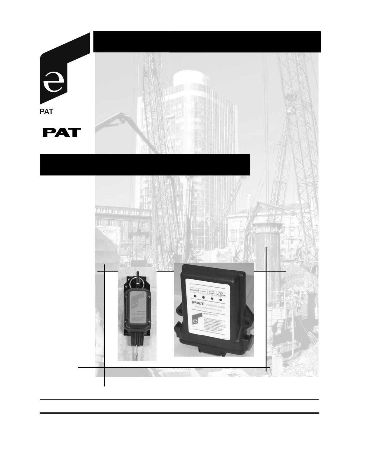
RADIO ANTI-TWO-BLOCK
INSTALLATION, OPERATOR’S & CALIBRATION MANUAL
P/N 031-300-190-136 Rev. F 03/26/203
Page 2

Page 3

Installation, Operator’s & Calibration Manual Radio Anti-Two-Block
NOTICE
PAT America, Inc. makes no warranty of any kind with regard to this material, including, but not limited
to, the implied warranties of merchantability and/or its fitness for a particular purpose.
PAT America, Inc. will not be liable for errors contained in this manual or for incidental or
consequential damages in connection with the furnishing, performance, or use of this manual. This
document contains proprietary information, which is protected by copyright, and all rights are reserved.
No part of this document may be photocopied, reproduced, or translated to another language without
the prior written consent of PAT America, Inc.
PAT America, Inc. reserves proprietary rights to all drawings, photos and the data contained therein.
The drawings, photos and data are confidential and cannot be used or reproduced without the written
consent of PAT America, Inc. The drawings and/or photos are subject to technical modification
without prior notice.
All information in this document is subject to change without notice.
MANUAL REVISIONS
REV DATE NAME DESCRIPTION
- 7/19/01 KH CREATED OPERATOR’S MANUAL, ECN 01-213
A 8/29/01 GJO REFER TO ECN 01-245
B 10/25/01 JR UPDATED WIRING DIAGRAM
C 02/20/02 JR UPDATED PHOTOS
D 04/19/02 JR Updated photos
E 11/18/02 CH ECN 02-275
F 03/26/03 CH ECN 03-037
© 2001 PAT GmbH, D-76275 Ettlingen / Germany © 2001 PAT America, Chambersburg, PA 17201, USA
©PAT Rev. F 03/26/03 190136_f
Page 4

Page 5

Installation, Operator’s & Calibration Manual Radio Anti-Two-Block
TABLE OF CONTENTS
1 GENERAL INFORMATION ...............................................................................................1
2 WARNINGS ....................................................................................................................... 1
3 SYSTEM DESCRIPTION...................................................................................................2
3.1 RECEIVER .................................................................................................................................. 3
3.1.1 LEDs : ...................................................................................... Error! Bookmark not defined.
3.1.2 ID button.............................................................................................................................. 3
3.2 TRANSMITTER / SWITCH.......................................................................................................... 4
3.2.1 Transmitter LED.................................................................................................................. 4
3.2.2 Storage of the A2B transmitter for Travel ........................................................................ 4
4 INSTALLATION.................................................................................................................5
4.1 TRANSMITTER/SWITCH............................................................................................................ 5
4.2 RECEIVER .................................................................................................................................. 6
5 SETUP/CALIBRATION .....................................................................................................7
5.1.1 Setup Overview ..................................................................................................................7
5.1.2 Clear Existing Setup Switches .......................................................................................... 7
5.1.3 First ID Setup ...................................................................................................................... 7
5.1.4 Second ID Setup .................................................................................................................8
6 OPERATION...................................................................................................................... 8
7 SYSTEM TESTING............................................................................................................9
8 MAINTENANCE .............................................................................................................. 11
8.1 BATTERY REPLACEMENT ..................................................................................................... 11
9 TROUBLESHOOTING..................................................................................................... 12
9.1 LED’S ........................................................................................................................................ 13
10 RADIO A2B SPARE PARTS...........................................................................................15
©PAT Rev. F 03/26/03 190136_f
Page 6

Page 7

General Information
1
1 GENERAL INFORMATION
The PAT Anti–Two-block System has been designed to warn the crane operator of a two-blocking
condition of the crane. If a two-blocking condition is approached, the system will warn the operator by
sounding an audible alarm, lighting a warning light and locking out those functions which may
aggravate the crane's condition, whenever applicable.
NOTE: The term "two-block" is a crane term that refers to a condition when the load handling device
comes in contact with the boom head. This condition, if not prevented, may cause the wire rope to
break, allowing the load to fall. Either raising the load into the boom head, or telescoping the boom out
without paying attention to the hoist line can cause a "two- block" condition.
2 WARNINGS
The PAT Anti-Two- Block System is an operational aid, which warns a crane operator of approaching
two-block conditions, which could cause damage to equipment and personal injury.
This device is not, and must not be a substitute for good, sound operator judgment, experience and
use of accepted safe crane operating procedures.
The responsibility for the safe operation of the crane remains with the crane operator who must ensure
that all warnings and instructions supplied are fully understood and observed.
Prior to operating the crane, the operator must carefully and thoroughly read and understand the
information in this manual to ensure that the operation and limitations of the system and the crane are
known.
Proper functioning is dependent upon proper daily inspection and observations of the operating
instructions set forth in this manual.
Caution: changes or modifications to this product which are not expressly approved by PAT could void
the user's authority to operate the equipment
.
©PAT Rev. F 03/26/03 190136_f
Page 8

2
Installation, Operator’s & Calibration Manual Radio Anti-Two-Block
3 SYSTEM DESCRIPTION
The PAT Radio Anti Two Block, RATB, uses state-of-the-art technology. The radio communication
electronics were designed cooperatively between PAT and OMNEX controls. OMNEX was chosen
because of its established name and proven experience with wireless communications in the
construction equipment industry. Our system transmits an OK signal ~ every two seconds on up to
three separate channels. This is to ensure accurate and consistent reception of data and to reduce the
possibility of unnoticed failure. The separate channels greatly reduce the probability of failure due to
external interferences.
Unique, serialized transmitter identifiers are used to ensure proper operation even though other
cranes are in the area.
The PAT RATB is easily configured to communicate with up to two transmitters. Simply by pressing
and holding the “ID” button for five seconds, the receiver can sense the transmitters being used and
configure the receiver to listen to only those transmitters. There are no numbers, ID’s or codes to
remember or write down.
The PAT RATB has been designed to be easily and quickly installed. It can be installed in an OEM
application in under an hour.
The PAT RATB works like our normal Anti-Two-Block. It alerts to an impending two-block condition.
This alert can come in the form of an audible alarm and visual LED or with the optional function
lockout if the crane is so equipped.
The PAT RATB transmitter is modular by design, containing three separate parts, the transmitter, the
switch and the battery housing. It was designed so these individual components can be replaced
easily and separately.
The receiver is mounted into a receiver box, which is water-tight when submerged in up to three feet
of water. The receiver box provides the following indications: Power (status), LINK, Low Battery, and
A2B.
If battery saving measures are used, the battery life will be greater than one year or up to two years,
even with transmitting every two seconds. Several power saving methods are incorporated into the
design of the electronics as well as the other hardware.
The receiver will work with either 12VDC or 24 VDC. It is fused to 1 Amp and protected to 36 VDC.
©PAT Rev. F 03/26/03 190136_f
Page 9

System Description
3.1 RECEIVER
Radio Anti-Two-Block Receiver Receiver Box
3.1.1 LEDs:
1.The POWER LED (Green) Shows that there is power to the system.
2.The LINK LED (Green) Indicates the status of the communication link
between the main hoist A2B transmitter and the
receiver. Failure of the communication link will
turn off the Green LED and turn off the output to
the lockout relay.
3.The LOW BATTERY LED (Yellow) Indicates that the battery of the main transmitter
needs to be replaced.
3
4. The A2B LED (Red) Indicates an impending two-block condition of the
main hoist. The Red LED will light when the loadhandling device has lifted the A2B weight. This
LED will light simultaneously with the engaging of
the lock out solenoids (if installed).
3.1.2 ID button
The yellow ID button, located in the lower right-hand corner of the receiver board, is used to set the
transmitter ID of the transmitter into the receiver.
©PAT Rev. F 03/26/03 190136_f
Page 10

4
Installation, Operator’s & Calibration Manual Radio Anti-Two-Block
3.2 TRANSMITTER / SWITCH
The transmitter and battery housing are made of a special plastic
that resists impact and will not become brittle even in low
temperatures.
3.2.1 Transmitter LED
The transmitter has an LED on the bottom for diagnostics. The LED
should be on when in a two-block condition or when the weight is
lifted. The LED will flash rapidly during a 2-block condition and will
stop flashing after the switch is in a two-block condition for more
than 15 seconds. The LED will flash randomly approximately every 2
seconds when the switch is transmitting. When in sleep mode, the
LED will not flash.
3.2.2 Storage of the A2B transmitter for Travel
The weight should remove from the switch when traveling to extend
battery life. The system is in permanent lockout and the system will
not function until the chain is unhooked. To use the feature, attach
any part of the chain into the hook. When it is desired to use the
switch again, simply unhook the chain to allow the switch to close.
The weight and chain must be hung from the switch and/or the chain
must be unhooked before the crane is operated.
©PAT Rev. F 03/26/03 190136_f
Page 11

Installation
5
4 INSTALLATION
4.1 TRANSMITTER/SWITCH
Install the standoff to the boom head using a 5/16x3/4” HEX bolt. The hole pattern for the standoff is
the same as that of conventional PAT A2B switches. In most cases the standoff can be mounted in
the same location as the conventional switch.
If not replacing an existing switch, the proper location would be one that allows the switch to rotate
freely without being obstructed by any part of the boom head. It should be mounted close to the dead
end mounting gusset. The switch should normally be mounted on the cab side of the crane.
For jib installations, locate the switch close to the jib head.
Remove the lynch pin from the standoff. Slide the A2B switch onto the standoff. Replace the lynch pin
into the standoff.
Install the weight and chain onto the A2B switch.
©PAT Rev. F 03/26/03 190136_f
Page 12

6
Installation, Operator’s & Calibration Manual Radio Anti-Two-Block
POWER
LINK
LOW
BATT.
A2B
ALARM
BOX MAXIMUM HEIGHT 1.375"
RECEIVER MODULE INTERNAL RELAY
RELAY SHOWN DEENERGIZED
(DURING NORMAL OPERATION RELAY IS ENERGIZED)
Wiring For Power Cable to Receiver Board Module
.
4.2 RECEIVER
The receiver comes packaged in a waterproof housing. The module must be mounted into a suitable
location using the supplied hardware. The location of the receiver should be in direct line of site of the
transmitter and not blocked by any metal between the transmitter and receiver.
©PAT Rev. F 03/26/03 190136_f
Page 13

Setup/Calibration
7
5 SETUP/CALIBRATION
5.1.1 Setup Overview
The PAT RATB is easily configured to communicate with up to 2 transmitters. Simply by pressing and
holding the yellow “ID” button for 7 seconds, the receiver can sense the transmitters being used and
configure the receiver to listen to only those transmitters. There are no numbers, ID’s or codes to
remember or write down.
ID SET
BUTTON
5.1.2 Clear Existing Setup Switches
Press and hold the yellow “ID” button for 15 seconds, the ID LED will begin to blink and then go off
when cleared.
switch setup to a single switch
Note: It is only necessary to complete this operation when changing from a duel
. When setup is complete, the new transmitter switch will over write
the old ID code with a new one.
5.1.3 First ID Setup
To configure the system, install batteries into the transmitter to be used. Turn on the crane power.
Open the receiver enclosure and slide out the receiver board. Press and hold the yellow ID button on
the OEM module for 7 seconds until the ID 1 LED blinks. Release the yellow ID button. The receiver
will search for a transmitter for the next 30 seconds. Pull on the cable of the transmitter and then
release it. The yellow ID 1 LED should now be on solid. The transmitter and receiver are now set up
and will work only with each other.
©PAT Rev. F 03/26/03 190136_f
Page 14

8
Installation, Operator’s & Calibration Manual Radio Anti-Two-Block
5.1.4 Second ID Setup
To program second radio a2b switch: Ground pin 3 of ithe receiver (as shown below). Install batteries
into the transmitter to be used. Turn on the crane power. Open the receiver enclosure and slide out
the receiver board. Press and hold the yellow ID button on the OEM module for 7 seconds until the ID
2 LED blinks. Release the yellow ID button. The receiver will search for a transmitter for the next 30
seconds. Pull on the cable of the transmitter and then release it. The yellow ID 1 LED should now be
on solid. The transmitter and receiver are now set up and will work only with each other.
The transmitter(s) and receiver are now set up to work only with each other. Test the system using the
instructions in section 7, System Testing.
6 OPERATION
The function of the system must be tested daily before each use of the crane hoist. Refer to PreOperation Inspection and Calibration Verification.
During the normal operation of the system the LINK and POWER LED’s should be on.
POWER LED
The POWER LED shows that the OEM module is getting power from the crane. The receiver is on any
time the crane is operating and supplying power to the system.
LINK LED
The LINK LED indicates the status of communication of the transmitter(s). During normal operation of
the system, the LED will be on. The LED is off when there is an interruption in the transmission. The
system should not be operated if the LINK LED is not lit.
LOW BATTERY LED
The low battery indicator will light indicating that you have a limited time to operate before the system
goes dead. When the battery level is to the point that it is too low to operate, the system will stop
functioning. Use any off-the-shelf alkaline C-cells; Duracell, Eveready, etc.
A2B ALARM LED
Indicates an impending two-block condition of the main hoist. The Red LED will light when the loadhandling device has lifted the A2B weight. This LED will light simultaneously with the engaging of the
lock out solenoids (if installed).
Test the electronics
Cycle the power to the system, each LED on the receiver will light for 2 seconds when the system is
powered. All of the indicator lights must come on or the system is not functioning properly. If any light
does not function, do not use the system until it has been repaired.
©PAT Rev. F 03/26/03 190136_f
Page 15

System Testing
9
7 SYSTEM TESTING
To test the electronics:
Each LED on the receiver will light for 2 seconds when the system is powered. All of the indicator
lights must come on or the system is not functioning properly. If any light does not function, do not use
the system until it has been repaired.
Following the successful testing, the LINK LED should come on. If the LED’s do not come on, there is
an error in the transmission. Do not use the system until it has been repaired or replaced. (Refer
Troubleshooting
To test the hoist limiting:
After the electrical connections have been checked to ensure that the system is properly connected for
the crane configuration, the following checks must be made:
The following tests must be performed with care to prevent damage to the machine or injury
to personnel. Proper functioning of the system requires successful completion of these
tests before operating the machine.
section.)
• Check the anti two-block switches and weights for free movement. If the operator cannot see
the load-handling device approaching the boom nose, an assistant (signal person) must watch
the load-handling device. The operator must be prepared to stop the machine immediately
should the RATB system not function properly. This is indicated by lighting the red warning
light, sounding the audible alarm and locking the following crane movements: hoist up,
telescope out and boom down.
• Manually lift the weight attached to the anti two-block switches. When the weight is lifted, the
audible alarm should sound, the anti two-block alarm light should light.
©PAT Rev. F 03/26/03 190136_f
Page 16
10
Installation, Operator’s & Calibration Manual Radio Anti-Two-Block
With optional lockout installed the following additional tests must be performed:
• Slowly raise the main boom load-handling device to create a potential two-block condition. When
the load-handling device lifts the weight, the audible alarm should sound, the anti two- block alarm
light should light and the motion of the load-handling device should be stopped. Lower the loadhandling device slightly to eliminate this condition.
• Slowly lower the boom to create a potential two-block condition. When the load-handling device
lifts the weight, the audible alarm should sound, the anti two-block alarm light should light and the
boom lowering function should be stopped. Lower the load-handling device slightly to eliminate this
condition.
• Slowly extend (telescope) the boom to create a potential two-block condition. When the load-
handling device lifts the weight, the audible alarm should sound, the anti two-block alarm light
should light and the boom telescope out function should be stopped. Lower the load-handling
device slightly to eliminate this condition.
If the light and audible alarm does not function as described and the crane movements are
not stopped, the system is not working properly. The malfunction must be corrected before
operating the crane.
If the crane is equipped with a second transmitter, repeat the test on the second transmitter.
©PAT Rev. F 03/26/03 190136_f
Page 17

Maintenance
11
8 MAINTENANCE
The only maintenance required is to change the batteries when required. Also, check the mounting
hardware daily to ensure that there is no damage. Replace any damaged parts before operating the
crane.
8.1 BATTERY REPLACEMENT
To replace the batteries, remove the 4 screws from the transmitter housing. Install 4 fresh batteries
into the proper location and direction as indicated on the battery holder. Make sure that the cardboard
tube is installed as shown.
LOOSEN 4 SCREWS
BATTERY DIRECTION LABLE
CARDBOARD TUBE
INSTALLED BATTERIES
©PAT Rev. F 03/26/03 190136_f
Page 18

12
Installation, Operator’s & Calibration Manual Radio Anti-Two-Block
9 TROUBLESHOOTING
LED’s
Receiver Board
Numbers from left to right on Receiver Board, above, are:
1. Link1 Green
2. A2B1 Red
3. LO BAT1 Red
4. Link2 Green
5. A2B2 Red
6. LO BAT2 Red
7. ID1 Orange
8. ID2 Orange
Note: The board must be removed from the housing in order to see the LED’s
©PAT Rev. F 03/26/03 190136_f
Page 19

Troubleshooting
13
9.1 LED’S
(Refer to Numbers below photo on previous page)
1.The LINK 1 LED Link1
2. The A2B 1 LED A2B1(Red) Indicates an impending two-block condition of the
3.The LOW BATTERY 1 LO BAT1 LED (Red) When the light goes off, it indicates that the
4. The LINK 2 LED Link2 (Green) Indicates the status of the communication link
(Green) Indicates the status of the communication link
between the main hoist A2B transmitter and the
receiver. Failure of the communication link will
turn off the Green LED and turn off the output to
the lockout relay.
main hoist. The Red LED will turn off when the
load-handling device has lifted the A2B weight.
This LED will light simultaneously with the
engaging of the lock-out solenoids (if installed).
battery of the main transmitter needs to be
replaced.
between the auxiliary hoist A2B transmitter and
the receiver. Failure of the communication link will
turn off the Green LED and turn off the output to
the lockout relay.
5. The A2B 2 LED A2B2(Red) Indicates an impending two-block condition of the
auxiliary hoist. The LED will turn off when the
load-handling device has lifted the A2B weight.
This LED will light simultaneously with the
engaging of the lock-out solenoids (if installed).
6.The LOW BATTERY 2 LED LO BAT2 (Red) When the light goes off, it indicates that the
battery of the main transmitter needs to be
replaced.
7. The ID 1 LED ID1(Orange) Lights to show the successful setup of the main
transmitter. This LED will stay on once the
transmitter is set up.
8. The ID 2 LED ID2(Orange) Lights to show the successful setup of the AUX.
Transmitter. This LED will stay on once the
transmitter is set up.
©PAT Rev. F 03/26/03 190136_f
Page 20

14
Installation, Operator’s & Calibration Manual Radio Anti-Two-Block
All LEDs are located inside the receiver box.
Problem Cause Solution
No LED’s light on
receiver
No power to receiver Make sure the module is getting power from the crane.
Check wiring.
Ensure correct polarity of the power.
Replace OEM receiver
Crane functions
locked out all the
time
No power to the
receiver
Check LED lights on module.
Make sure the module is getting power from the crane.
Check wiring.
Ensure correct polarity of the power.
Replace OEM receiver
Crane functions
locked out all the
Incorrect wiring Check for power to lockout device.
time
Crane functions
locked out all the
time
No reception. Check if the green Link LED is on. The green Link1 LED
must be on for single hoist operation. Link1 and Link2 must
be on for 2-hoist operation.
See Link 1 LED troubleshooting.
Crane functions
locked out all the
Fault in receiver
module.
Check relay output voltage from receiver to lockouts
time
Transmitter LED
does not flash
Pull switch wire rope. Red LED will flash ~each 2 sec.
Replace batteries.
Replace transmitter.
Link 1 LED not on ID1 not set. Set the ID of the transmitter. See Section 5, Setup.
Link 1 LED not on Poor communication
caused by
interference.
Link 1 LED not on Object blocking the
transmission path.
Remove potential interference sources from the area.
Mount the receiver in a different location.
Improper location of the receiver. Move the receiver to a
line of site location.
Check antenna
Link 1 LED not on Fault in the main
transmitter.
Pull main switch wire rope.
Replace batteries.
Replace transmitter.
Link 2 LED not on ID2 not set. Set the ID of the transmitter. See Section 5, Setup.
Link 2 LED not on Poor Communication
caused by
interference.
Link 2 LED not on Object blocking the
transmission path.
Remove potential interference sources from the area.
Mount the receiver in a different location.
Improper location of the receiver. Move the receiver to a
line of site location.
Check antenna.
Link 2 LED not on Fault in the aux
transmitter.
Pull main switch wire rope.
Replace batteries.
Replace transmitter.
LO BAT1 or LO
BAT2 LED off
©PAT Rev. F 03/26/03 190136_f
No or low batteries in
the transmitter.
Replace batteries.
Page 21

Radio A2B Spare Parts
10 RADIO A2B SPARE PARTS
031-300-060-488 Radio A2B receiver
031-300-060-377 Cable Assembly 12’
Note: part number may change depending on length
15
1
2
1) 031-300-060-484 Radio A2B transmitter
assembly
2) 031-300-100-722 A2B flag assembly
031-300-050-262 Radio A2B transmitter
031-300-050-537 Battery cover
©PAT Rev. F 03/26/03 190136_f
Page 22

16
Installation, Operator’s & Calibration Manual Radio Anti-Two-Block
031-300-050-536 Card board tube 031-300-060-022 Radio A2B switch
031-300-050-264 A2B mounting plate
031-300-050-276 A2B Mounting standoff
031-300-210-012 Weight and chain
031-300-100-037 Chain connector, quick link
031-300-050-272 Lynch pin
©PAT Rev. F 03/26/03 190136_f
 Loading...