

Page 1
Revised: 23/08/2012 Printed
1
Printed: 20/03/2013
COONARA “HERMITAGE”
HIGH EFFICIENCY GAS LOG SPACE HEATER
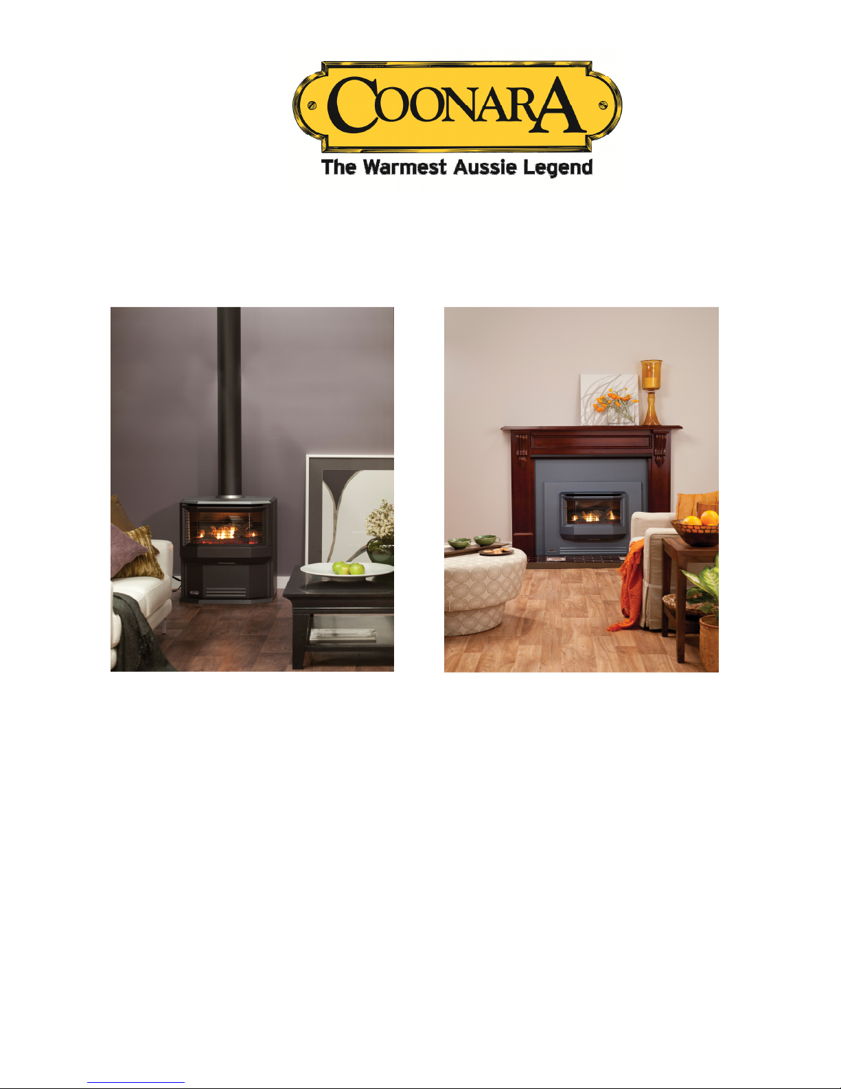
CONSOLE MODEL INBUILT MODEL
CUSTOMER OPERATING INFORMATION
&
INSTALLATION INSTRUCTIONS
Serial Number of Heater: ____________ Model: ___________________
Hermitage Gas Heaters
ARE AUSTRALIAN OWNED & MANUFACTURED BY
SHAMIC SHEETMETAL
SHAMIC SHEETMETALSHAMIC SHEETMETAL
SHAMIC SHEETMETAL
(AUST.) PTY. LTD.
PO BOX 8, KILSYTH, VIC. 3136PH: 03 9737 5300 FAX: 03 9761 6455
www.shamicheating.com.au
Page 2

Revised: 23/08/2012 Printed
2
Printed: 20/03/2013
WARNING
THE FOLLOWING INSTRUCTIONS MUST BE CARRIED OUT OR
WARRANTY MAY BECOME VOID.
Heater must be installed by an authorized person. You must obtain a license
number from the installer.
Heater must be placed on a flat level surface. Inbuilt models must be placed
on AC sheeting, to prevent unit from rattling.
Heater must be checked for scratches or dents prior to installation.
All glass must be fitted with a screw driver not a drill. If glass is broken upon
installation due to the screws being tightened too much, it will not be classed
under warranty.
Further safety precautions and installation instructions are contained
throughout this manual.
Please read the manual before installation.
Page 3

Revised: 23/08/2012 Printed
3
Printed: 20/03/2013
C
ONTENTS
PRODUCT FEATURES 4
CUSTOMER OPERATING INSTRUCTIONS 6
SAFETY PRECAUTIONS
SAFETY FEATURES 7
INSTALLATION INSTRUCTIONS 8-14
LOG INSTALLATION & WIRING DIAGRAM 15
GAS VALVE ADJUSTMENT 16
TROUBLESHOOTING GUIDE 17
DIMENSIONS & WARRANTY 18-19
CARE OF APPLIANCE 20
SERVICE CONTACT & WARRANTY INFORMATION 21
Page 4
Revised: 23/08/2012 Printed
4
Printed: 20/03/2013
P
RODUCT FEATURES
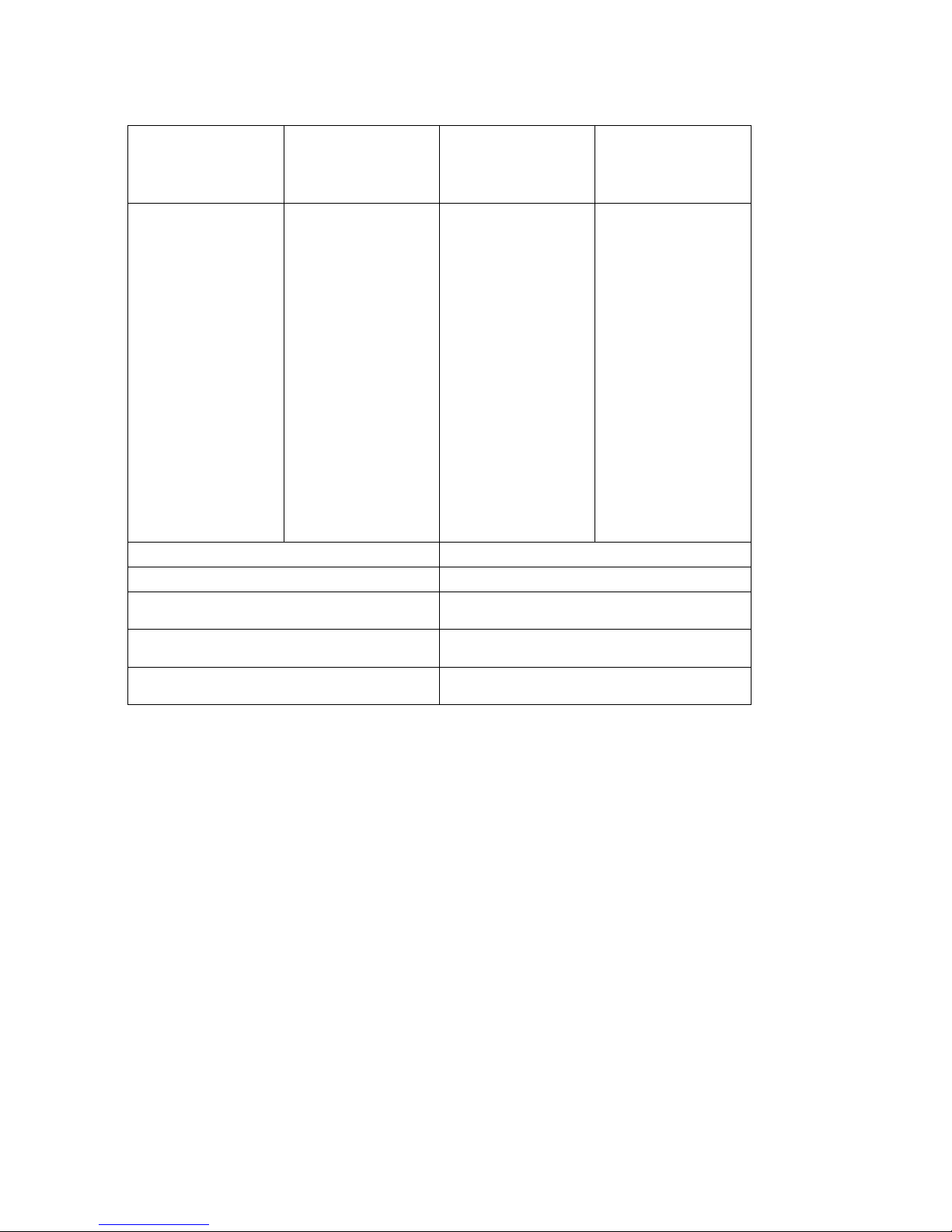
MODEL-Hermitage,
Chateau, Chateau II
GAS TYPE
NATURAL
L.P.G
Manufacturer
MODEL TYPE
GAS INPUT
HIGH
LOW
HEAT OUTPUT
HIGH
LOW
Efficiency
Injector Size
Manifold Pressure
High
Low
A.G.A Approval
No. to Code AS 45532008
Freestanding
Inbuilt
33 MJ/h
23 MJ/h
7.6 kW
5.2 kW
83 %
2.8 mm
1.0 kPa
0.48 KPa
AGA 6165 G
Freestanding
Inbuilt
33 MJ/h
23 MJ/h
7.6 kW
5.2 kW
83 %
1.6 mm
2.6 kPa
1.3 KPa
AGA 6165 G
Shamic Sheetmetal
(Aust.) Pty.Ltd
.
PO BOX 8,
KILSYTH,
VIC. 3136
To be installed by an
authorized person in
accordance with
installation instructions
provided with the
appliance.
Electrical Conform to AS3100 240V 50 Hz 120 Watts Max
Air Pressure Switch
Aria 380 series (5471)
Cut in Pressure 45 Pa
Cut out Pressure 40 Pa
Electrical Connection Standard Flex. 2 Mt. 3 Pin Plug
Hermitage Freestanding and Inbuilt gas log heaters.
33 Mj/h Gas Input Natural Gas and LPG.
7.19 kW Output.
Energy rating 4.2 Stars (Free standing) 4.6 stars (Inbuilt)
Electronic ignition.
Two heat settings.
External combustion air intake - prevents de-oxygenation of room air.
Delayed start room fan - prevents cold air being circulated at start-up.
Delayed stop room fan - aids cool down of unit when switched off.
Power flue.
Integrated safety features.
The Coonara “Hermitage” Freestanding and Inbuilt and the Chateau and Chateau II Inbuilt models are
approved by the Australian Gas Association to code AS4553-2008 for gas space heating appliances.
AGA Approval No. 6165
Page 5

Revised: 23/08/2012 Printed
5
Printed: 20/03/2013
This appliance shall only be installed in accordance with:
AS/NZS 5601 (Gas Installation Standard),
Manufacturer’s Installation Instructions,
Local Gas Fitting Regulations,
Municipal Building Codes.
This appliance must only be installed and serviced by an authorised person
Please store this manual in a safe place for future reference
Page 6

Revised: 23/08/2012 Printed
6
Printed: 20/03/2013
C
USTOMER OPERATING INSTRUCTIONS
The Coonara “Hermitage”, Gas Log Space Heater has been designed for simple efficient operation, with only
two switches for ignition and both High And Low settings.
P
RE-OPERATION CHECKS
Prior to operating the heater, ensure that the flue terminal is not obstructed. Furthermore, make sure there are
no combustible objects leaning against, resting on, or within the immediate vicinity of the unit. Check that the
heater main power and gas supply are connected and switched on.
O
PERATING THE HEATER
The heater controls for the freestanding model are located at the top right hand side of the appliance toward
the rear. Controls for the inbuilt model are located on the top front right hand fascia.
To operate the heater, press the smaller of the two switches labeled On/Off to the “On” position, the
electronic control will commence a safety check period of approximately 8 seconds prior to igniting the
heater. The room fan will start operating once the appliance has begun to heat-up, thus preventing cold air
circulation.
To operate on High fire/High fan mode, set the larger switch to the “High” position. When the area to be
heated has reached a comfortable temperature level set the switch to the “Low” position.
The heater may be switched on or off, in either the High or Low settings.
To operate the heater using the Thermostat please refer to the “7000 Series Thermostat User Manual” for
further information.
Note: At start up, if the “High” position has been selected the heater will only ignite on the “Low” setting and
will automatically switch to the “High” setting after an initial warm up period.
T
URNING THE APPLIANCE OFF
Set the smaller of the two switches to the “Off” position.
The room fan will continue to operate for a short period while the heater cools down.
To turn the heater off using the Thermostat please refer to the “7000 Series Thermostat User Manual” for
further information.
Note 1: This appliance cannot be operated without the fan operating.
Note 2: Due to the performance and efficiency of the heater, steam may be noticed coming from the flue
terminal on days of low temperature.
Note 3: As this appliance has a luminous flame effect some slight carbon depositions may occur.
Note 4: During first time firing of this appliance, an odour may be noticed for a short period as the paint
cures. It is advisable to leave a window open during the first few hours of the very first operation only.
S
AFETY PRECAUTIONS
IMPORTANT POINTS
!!!! DO NOT place articles or clothing on or against this appliance.
!!!! DO NOT use or store flammable materials near this heater.
!!!! DO NOT place any item containing liquid on the heater.
!!!! DO NOT spray aerosols in the vicinity of this appliance when it is in operation.
!!!! DO NOT modify this appliance.
!!!! ALWAYS supervise young children near the appliance.
It is recommended that a secondary guard be used, to prevent access to appliance by children, as outer
panels of this appliance may reach high temperatures.
Note: In the event that the electricity supply cord is damaged it must be replaced with Coonara part #
6306, obtainable from authorised gas retailers.
Page 7

Revised: 23/08/2012 Printed
7
Printed: 20/03/2013
SAFETY FEATURES
Automatic Shut-Off: Should the flame extinguish for any reason, there is an automatic close off of the gas
supply.
Note: fans will continue to operate as normal.
Over Temperature Protection: In the event of the room fan failing, blockage of airways, or incorrect gas
installation, the gas supply will be automatically closed off to prevent the appliance over-heating.
Record the following information in the space provided.
Purchased from:
Name
Address
Phone No Date of purchase
Serial No of Appliance
To be completed by installer:
Name License No
Address
Phone No Date installed
Note: This appliance can only be installed by an authorized person who is responsible for its correct
operation at the time of installation.
AS/NZS 5601 Appliance Commissioning
9.2 The commissioning of an appliance shall take full account of special design features, the manufacturer’s
instructions and the appliance safety requirements.
9.3 The commissioning of an appliance shall include all of the following
(a) Compliance with clauses 2.4.2 and 2.6
(b) The appliance is to be checked to ensure safe working order.
(c) The burner of the appliance is to be lit and where necessary adjusted, in accordance with the
manufacturers instructions
(d) The consumer, where available, is to be instructed on the safe and correct operation of the appliance and
any auxiliary equipment.
(e) The appliance operating instructions are to be handed to the consumer, or if the consumer is not present,
the instructions are to be left in a suitable location on the premises.
Page 8

Revised: 23/08/2012 Printed
8
Printed: 20/03/2013
I
NSTALLATION – Must be placed on a flat level surface to prevent rattles.
Freestanding Model
Note: Not intended for fireplace insert.
Only to be carried out by an authorised person!
Note: Prior to final positioning of the heater consider the location that the flue will penetrate the wall / ceiling
to avoid contact with combustible fixtures such as; roof trusses, wall framework, etc. Furthermore, a
minimum distance of 1 metre should be maintained between the appliance and flammable objects such as
curtains, furniture, etc. Also consider minimum distances to combustible surfaces (ref page 14).
A. Carefully remove the carton from the heater, remove heater from pallet,
B. Position the heater where desired,
C. Remove the 2 screws holding the fascia assembly to the lower cover panel, the fascia is secured to the
heater body by 4 lugs and can be removed by lifting the fascia upward approximately 5mm and then
forward,
D. Check! The label at the rear of the fire box to confirm gas type is appropriate for the gas supply
available,
E. Remove the lower cover panel by first rotating the top of the panel toward you, and then lifting up and
away from appliance,
F. Loosen the lower glass retaining bracket screws and completely remove the top bracket, remove the glass.
G. Carefully unpack the logs from their separate carton and position them back into the firebox (refer
diagram page 14),
H. Install flue (see following section),
I. Connect the gas supply, purge gas line, check all connections for leaks, then check pressures (refer to
pressure settings on page 15) and adjust if necessary.
J. Reassemble heater in reverse order of above, connect electrical cord to correctly wired and earthed 240
volt AC power point,
K. Operate heater, check operation of heater on both High and Low, ensure fan operates after initial warm up
period (refer trouble shooting guide page 15 should any problems occur).
Note: This appliance will not operate if a power point, power board or extension lead has reverse
polarity.
Instruct customer of correct operating procedure.
FLUE INSTALLATION
Vertical Flue Installation
1. Cut a hole 205mm diameter in the ceiling at the desired location, cut a hole of sufficient size
for 6” (152mm) outer flue case to pass through roofing material in line with hole in ceiling,
2. Run a plumb line from the centre of hole in ceiling to the flue outlet of the heater (this will
ensure flue will run true vertically),
3. Attach the ceiling ring supplied with the flue kit to the ceiling centrally over hole in ceiling,
4. Fit tapered flue dress trim (wide end toward heater) over flue outlet in top of heater,
5. Fit flue inner & outer flue lengths to spigots on top of heater until desired length through roof
is achieved.
6. Use a suitable sealant at each end of inner flue – High temperature silicon sealant
Note: Crimped ends must point upwards on both inner & outer flues.
7. Cut outer flue casing to ensure inner Flue (exhaust pipe) protrudes 50 mm above outer casing!
8. Suitably flash outer flue at roof penetration,
9. Fit cowl to end of flue ensuring both inner and outer flanges cover respective casings adjust
length of inner flue by cutting or extending as required. Use sealant on inner flange joint.
WARNING
Heater must be checked for scratches or dents prior to installation.
Once the Heater is installed scratches or dents are not covered by warranty.
Page 9
Revised: 23/08/2012 Printed
9
Printed: 20/03/2013
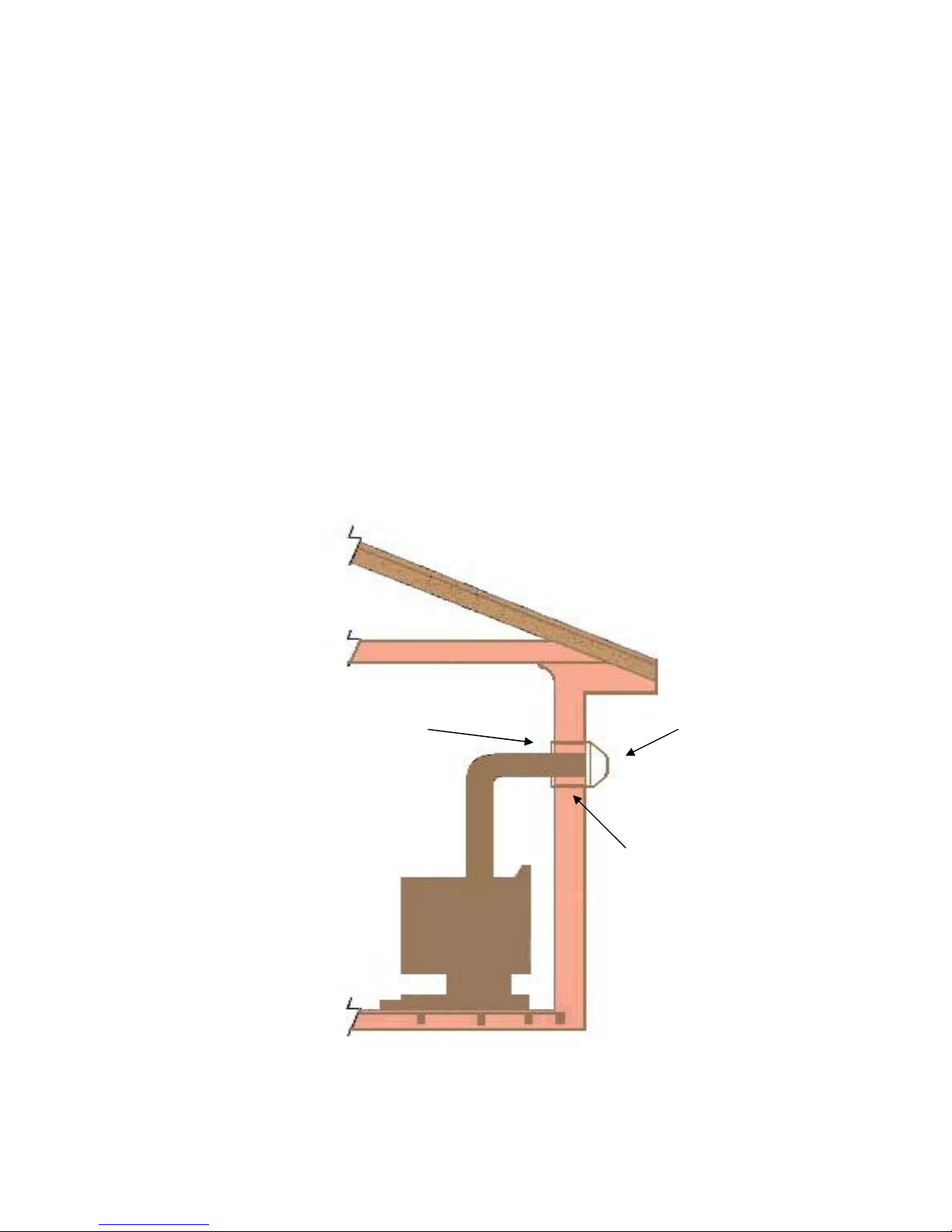
90 Degree Wall Penetration Flue Installation
1. Determine the exact location for the heater
2. Attach the outer 900 mm flue and 90 degree bend to the heater
3. Mark the exact location for the wall penetration
• Determine that you will not be cutting through any vertical wall studs.
• Check that the location of the wall-mounted terminal conforms to the requirements of
AS/NZS 5601 – Location of a Flue Terminal.
4. Cut a hole 205 mm in diameter through the wall.
5. Attach the internal wall plate centrally over the hole.
6. Fit the tapered flue dress trim (wide end towards the heater) over the flue outlet on top of the
heater
7. Fit the inner and outer 900mm flue lengths to spigots on top of the heater
8. Fit the 525mm inner and 450mm outer flues through the wall plate.
9. Fit the inner and outer 90 degree bends to the 900mm lengths.
10. Fit the short inner and outer lengths to the 90 degree bends.
11. Trim the inner flue to 50mm longer than the outer flue.
NOTE.- It may be necessary to trim the outer flue depending on wall thickness.
12. Attach the cowl backing plate to the wall. Seal with silicon sealant.
13. Fit the wall cowl to the flues and attach to the backing plate.
1.25” (32mm) clearance
from flue pipe to
combustible materials
Flue ring
Page 10

Revised: 23/08/2012 Printed
10
Printed: 20/03/2013
Rear vent Flue Installation
1. Determine the exact location for the heater
2. Attach the outer 900 mm flue to the heater
3. Mark the exact location for the wall penetration
a. Determine that you will not be cutting through any vertical wall studs.
b. Check that the location of the wall mounted terminal conforms to the requirements of
AS/NZS 5601 – Location of a Flue Terminal.
4. Cut a hole 205 mm in diameter through the wall.
5. Attach the internal wall plate centrally over the hole.
6. Fit the inner and outer 450mm flue lengths to spigots on the rear of the heater.
7. Trim the inner flue to 50mm longer than the outer flue.
NOTE- it may be necessary to trim the outer flue depending on wall thickness.
8. Attach the cowl backing plate to the wall. Seal with silicon sealant.
9. Fit the wall cowl to the flues and attach to the backing plate.
Inbuilt models must be placed on AC sheeting and flat level surface to
prevent the unit from rattling.
Heater must be checked for scratches or dents prior to installation.
Recess plaster or masonry around back of on/off switch to allow fascia to sit
flush on wall.
I
NSTALLATION
Inbuilt Model
Only to be carried out by an authorised person!
1. Carefully remove the carton from the heater, - remove heater from pallet.
2. Unpack Flue Kit (packaged separately).
3. Remove the 2 screws holding the fascia assembly to the heater surround. The fascia is secured to
the heater surround by 2 lugs and can be removed by lifting the fascia upward approximately 5
mm and then forward.
4. Remove the 2 screws holding the fascia surround to the firebox body. This surround is located by
2 lugs, and is removed by lifting upwards approximately 5 mm then forward.
5. Check the label on the rear of the firebox to confirm gas type is appropriate for the
gas supply available
6. Loosen the lower glass retaining bracket screws. Completely remove the top glass
retaining bracket. - Remove the glass.
7. Unpack the log set from their separate carton and position them in the firebox as shown in
the diagram on Page 14.
8. Install the flue – see Inbuilt Model – Flue installation Pages 10 & 11.
9. Locate the heater body into the fireplace cavity, or, pre-built wall cavity. Connect the gas supply,
purge gas lines, check all connections for leaks, check pressures (refer page 15)
10. Fix the appliance firmly in position using the 4 angle brackets fixed to the heater body.
11. Connect the air inlet and exhaust flexible pipes to the outlets on the heater body.
NOTE – The EXHAUST flue is colour coded RED at the heater body, both ends of the flexible flue
pipe and at the collector box on the flue terminal assembly.
12. Re-assemble heater in reverse order of above. Connect electrical cord to correctly wired and
earthed 240 Volt AC power point.
13. Operate heater, check operation on both, Hi and Low settings. Ensure fan operates after
initial warm-up period. (Refer Trouble Shooting Guide page 15 should any problems occur.)
Instruct customer of correct operating procedure.
Page 11
Revised: 23/08/2012 Printed
11
Printed: 20/03/2013
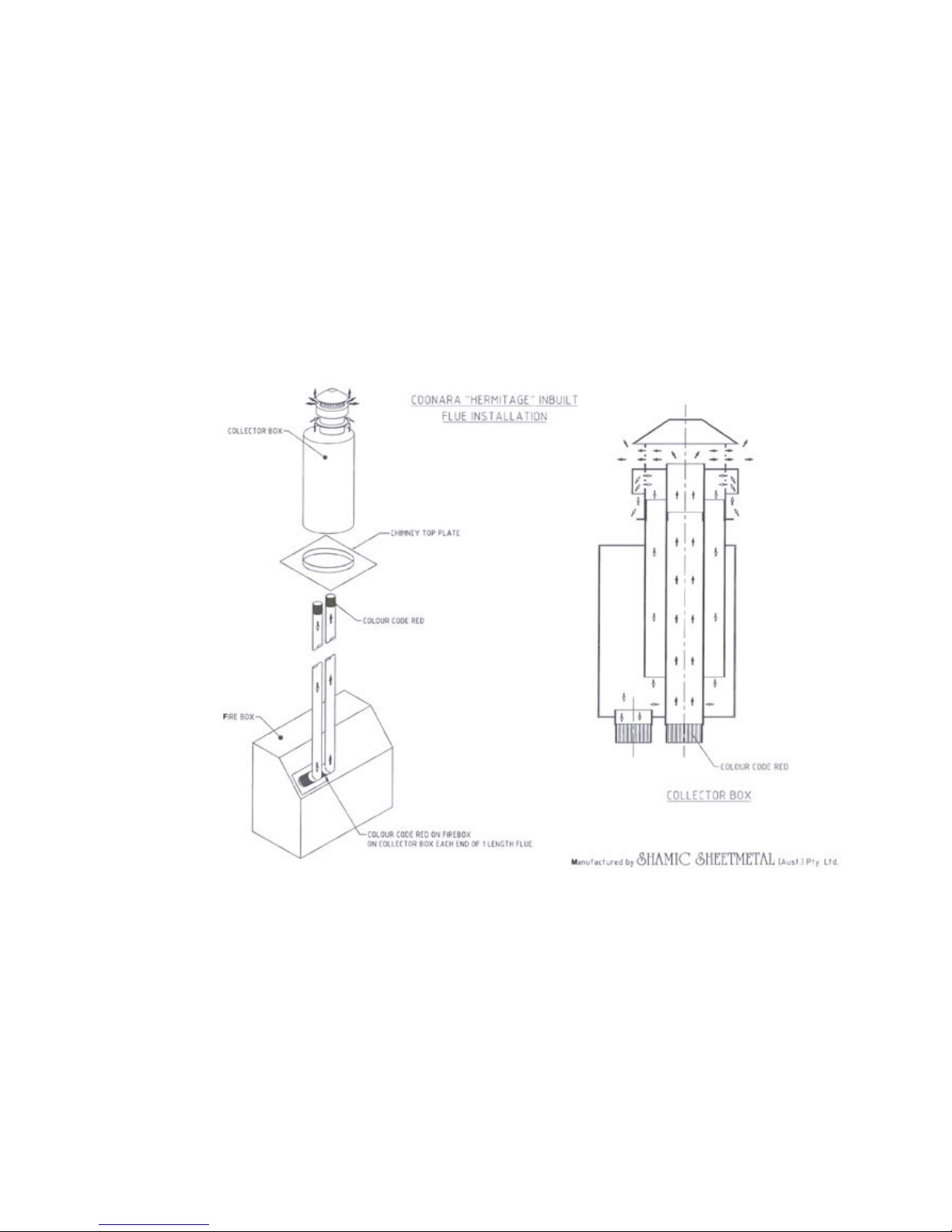
VERTICAL FLUE INSTALLATION
INBUILT MODEL
1. Connect flue terminal to both flexible flue pipes. The exhaust pipe is colour coded RED at
each end, the exhaust outlet on the heater body and the exhaust port at the flue terminal.
2. Feed both flexible pipes down the flue cavity.
3. Fix flue terminal securely to top of flue cavity and seal to prevent water entry. Seal with Hi
Temperature waterproof silicon sealant prior to cementing to chimney top, pop rivet circular
flange to base of collector box. (Chimney installation only).
4. Connect flexible flue pipes to the correct outlet at the heater body Exhaust being colour RED
Page 12
Revised: 23/08/2012 Printed
12
Printed: 20/03/2013
INBUILT MODEL
Horizontal Flue Installation
Installation into an existing fireplace.
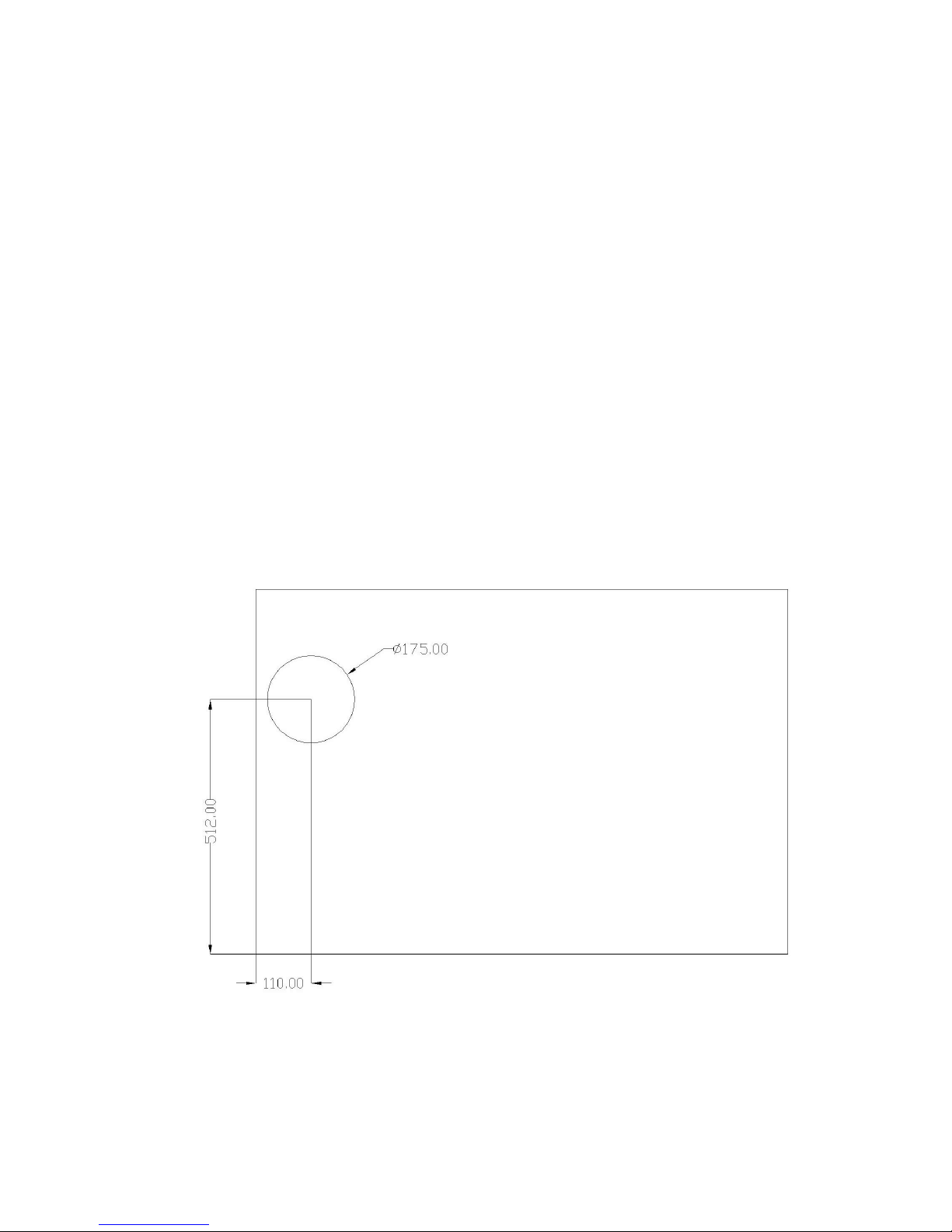
1. Mark the centre line of the heater location and using the diagram (Fig 1) determine the
exact location for the flue pipes and flue terminal.
NOTE – Check that the location for the flue terminal conforms to the requirements of
AS/NZS 5601 location of a flue terminal.
2. Cut the required opening in the brick work.
NOTE – Allow sufficient space for the gas connection.
3. Connect Gas
4. Fit the bends and short inner and outer flue pipes to the heater spigot.
5. Slide the heater into position with the flue pipes protruding through the hole in the rear of
the fireplace.
6. After final positioning – Fix the appliance firmly into position using the fixing brackets on
either side of the heater casing.
7. Trim the inner flue to 50mm longer than the outer flue
NOTE – It may be necessary to trim the outer flue depending on wall thickness.
8. Attach the cowl backing plate to the wall. Seal with silicon sealant
9. Fit the wall cowl to the flues, Attach cowl to the backing plate.
Fig 1: Rear of heater showing exact location of flue (shown from rear).
Page 13

Revised: 23/08/2012 Printed
13
Printed: 20/03/2013
Installation in a Stud wall cavity.
1. Mark the exact location of where the heater is to be located with an outline
720mm wide by 615mm high
2. Check that location for the flue terminal conforms to the requirements of AS/NZS
5601 Location of a Flue Terminal.
3. Cut out the plaster board and timber supports (re-position supports if necessary)
4. Refer to figure 1, and continue as described on previous page.
5. When completed, fit the “console cover” supplied to the heater fascia surround.
Fit to the heater body. Attach heater fascia.
Installation through the wall.
1. Mark the exact location of where the heater is to be located with an outline
720mm wide by 615mm high.
2. Check that location for the flue terminal conforms to the requirements of AS/NZS
5601
Location of a Flue Terminal.
3. Cut out the plasterboard and timber supports (re-position if necessary). Cut out
the outer brickwork.
4. Fit the bends and the short inner and outer to the heater spigot
5. Feed the gas line through the hole located at the lower right hand side of the outer
weather cover (provided) and the flue pipes through the pre-punched hole for the
flue pipes on the upper left hand side.
6. Locate the appliance, connect gas.
7. Fit the outer weather cover over the exposed heater body and screw to the outer
wall. Also use a silicon sealant.
8. Trim the inner flue to 50mm longer than the outer flue.
9. Fit the cowl backing plate to the outer weather cover (Also use a silicon sealant).
10. Fit the cowl to the flue pipes and then to the cowl mounting plate.
11. Firmly fix the appliance in to position using the brackets on each side of the
heater casing.
12. Replace fascia surround and Fascia.
External weather cover assembly/installation.
The weather cover is supplied partially assembled with only the base panel to be attached to
complete the assembly (screws provided)
There is a moveable cover plate at the lower right hand of the rear panel for fitment of the gas
connection.
The horizontal cowl mounting plate (which is common for both full and partial wall
penetrations) has a total of 8 pre-drilled holes. For attachment to the external weather cover,
the 4 inner 4.5 mm holes are utilized (screws provided). When attached to masonry or
weatherboard the 4 outer 6mm holes are utilized.
Note: when the weather cover and cowl are attached it is necessary to seal the top and side
edges with silicone to prevent water entry.
Page 14
Revised: 23/08/2012 Printed
14
Printed: 20/03/2013
IMPORTANT!
The Hermitage Gas Log Heater
must always be vented to the outside!
IMPORTANT!
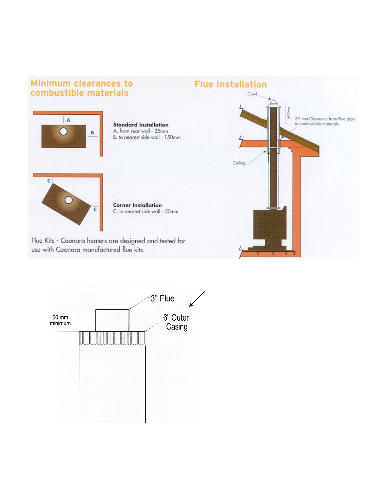
Cut outer flue casing to ensure
inner Flue (exhaust pipe)
protrudes 50 mm above outer
casing!
Crimped ends must point
upwards!
Page 15
Revised: 23/08/2012 Printed
15
Printed: 20/03/2013
I
NSTALLATION OF LOG SET
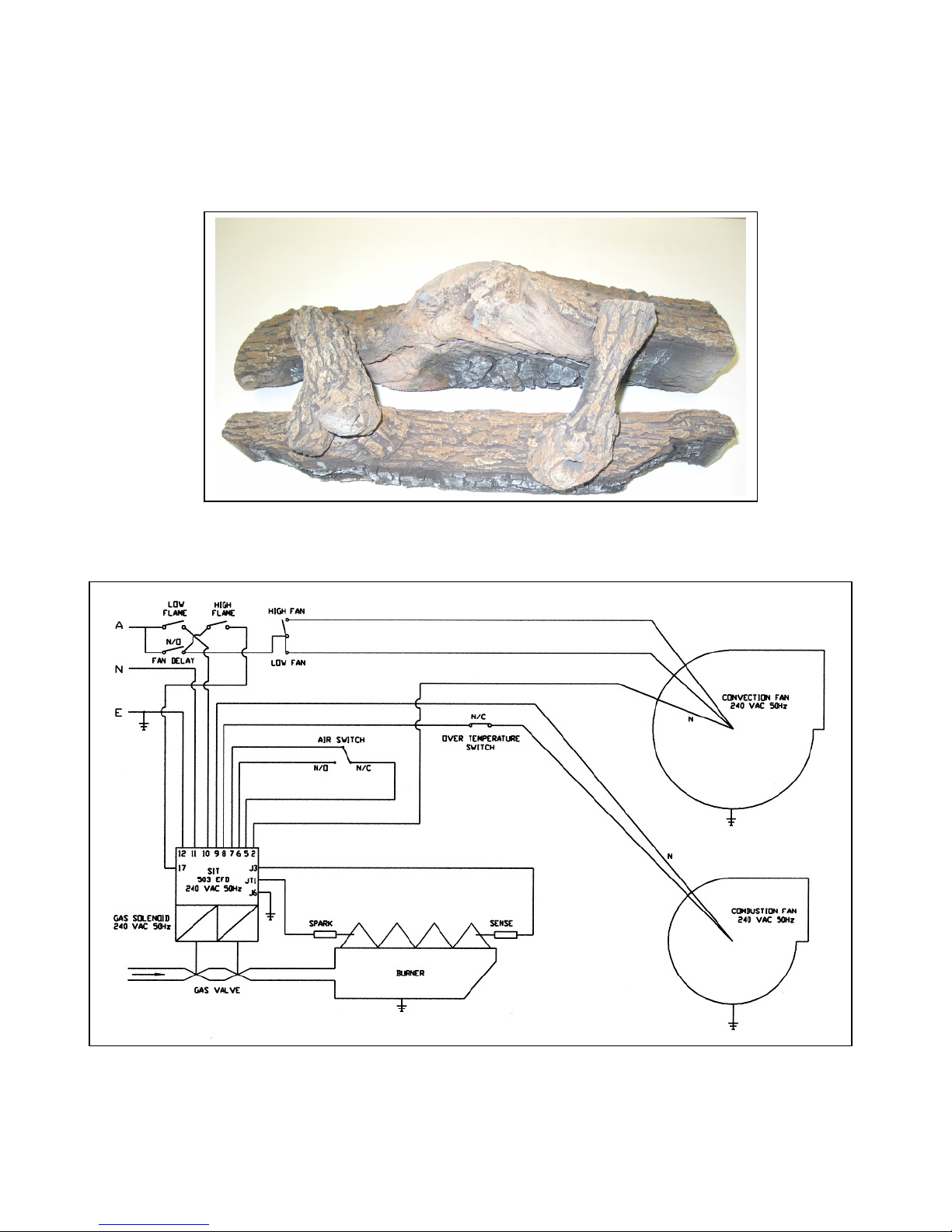
1. Place the rear log on the top rear burner plate as shown.
2. Place front log on the front section of the burner.
3. Fit the cross logs (as illustrated below) to the pins located on the front and rear logs. Logs should
not touch the sensor or sparker.
Above diagram shows correct orientation of logs
WIRING DIAGRAM
G
AS VALVE ADJUSTMENT
The gas valve pressure adjustments must be checked during installation, and if necessary corrected to
suit the gas type available. (See label inside of lower cover panel or this page for required pressure
settings).
Page 16
Revised: 23/08/2012 Printed
16
Printed: 20/03/2013
HERMITAGE GAS VALVE
SIT 843
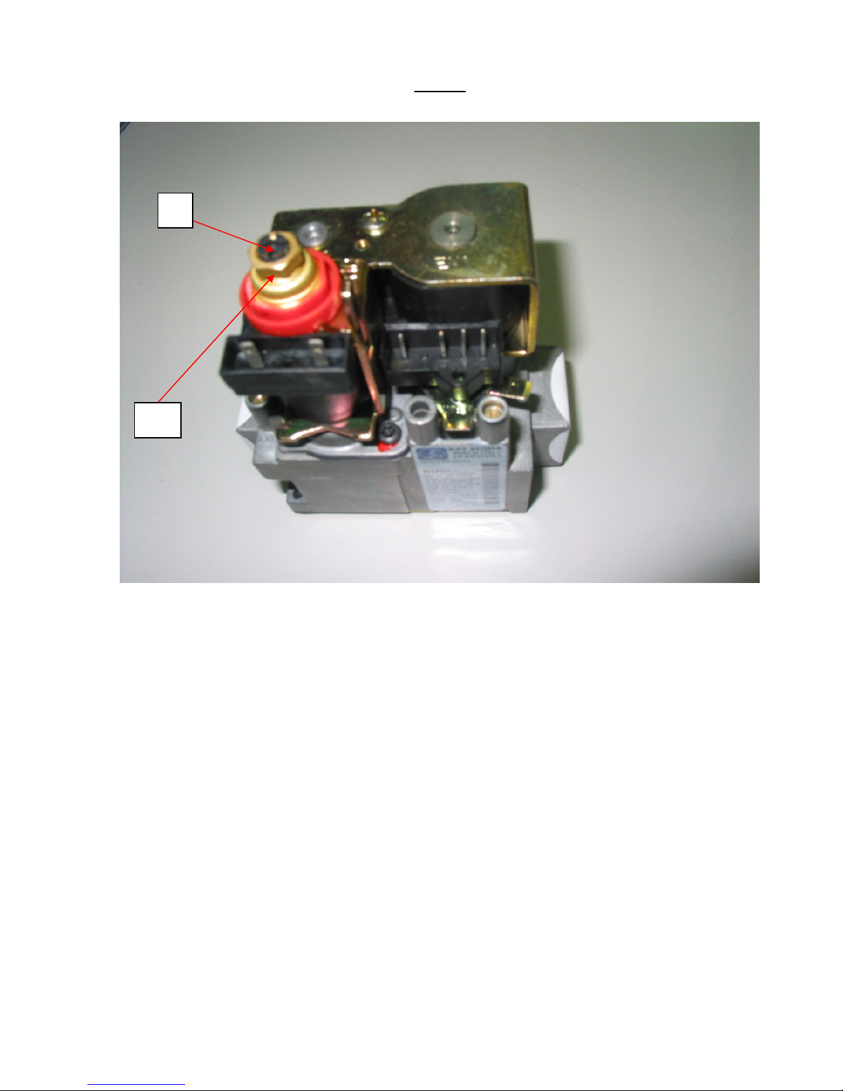
“A” represents the low gas adjustment. Turn the screw clockwise to increase gas pressure.
“B” represents the high gas adjustment. Turn the nut clockwise to increase gas pressure.
Natural Gas
Burner test point pressure – HIGH 0.9 kPa, LOW 0.48 kPa
Primary air shutter adjustment – fully open (Freestander)
fully open (Inbuilt)
Natural gas injector orifice – 2.8mm diameter
LPG Gas
Burner test point pressure HIGH 2.75 kPa, LOW 1.30 kPa
Primary air shutter adjustment – fully open (Freestander)
fully open (Inbuilt)
Propane gas injector orifice – 1.6 mm diameter
A
B
Page 17
Revised: 23/08/2012 Printed
17
Printed: 20/03/2013
T
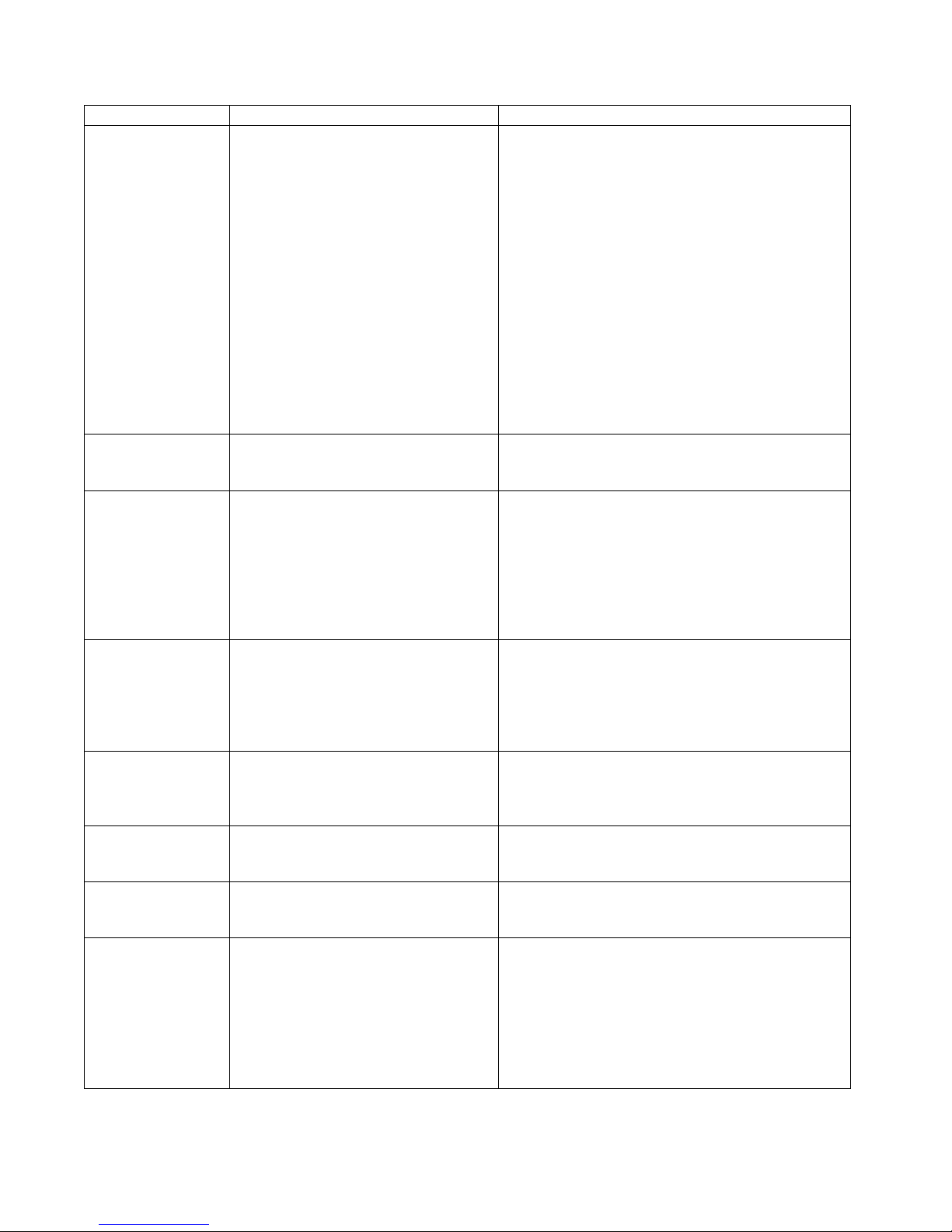
ROUBLESHOOTING GUIDE
PROBLEM POSSIBLE CAUSE REMEDY
Appliance fails to
ignite.
No gas or supply pressure insufficient.
No electrical supply.
Incorrectly wired power point.
Incorrect gas valve adjustment.
Insufficient time allowed between
attempts.
Internal wiring disconnected.
Ensure gas supply connected, purged, and pressure
appropriate.
Ensure unit plugged in and switch is on, check
supply fuse.
Check supply. Active, neutral, & earth must be
correctly orientated and connected.
Adjust valve pressures.
Wait at least 15 seconds for unit to purge
combustion chamber after switching on.
Check all plugs inside appliance are connected
properly and correctly located, Ensure operation of
combustion fan & air pressure switch.
Unit will not
operate on Low.
Incorrect gas valve adjustment.
Incorrect or loose wiring.
Adjust valve.
Check wiring.
Room fan not
operating.
Insufficient time allowed.
Loose wiring.
Fan not located correctly.
Fan blocked.
Fan has a delayed start and will not start until unit
warms-up.
Check wiring.
Install fan in correct location.
Remove and clean fan.
Unit cuts out after a
period of time then
cycles on and off.
See “Room fan not operating”
Heat exchanger blockage.
Excessive pressure or incorrect gas
type.
See “Room fan not operating”
Clean heat exchanger.
Ensure correct gas type, injector size, and pressure
setting.
Excessive carbon
(soot) deposits on
inside of firebox,
logs, and/or glass.
Incorrect gas type or pressure setting.
Primary air shutter incorrectly adjusted
for gas type.
Ensure correct gas type, injector size, and pressure
setting.
Adjust primary air shutter.
Excessive flame
height.
Incorrect gas type or pressure setting. Ensure correct gas type, injector size, and pressure
setting.
Excessive flame
“lift off”
Flue or inlet blockage.
Recirculation of flue gases.
Clear blockage.
Flue incorrectly installed.
Unit fails to heat. See “Room fan not operating”
Incorrect gas type or pressure setting.
Gas supply blockage.
See “Room fan not operating”
Ensure correct gas type, injector size, and pressure
setting.
Check injector, burner supply pipe, & valve for
foreign matter.
All service work to be carried out by a qualified & authorised person.
Page 18

Revised: 23/08/2012 Printed
18
Printed: 20/03/2013
D
IMENSIONS
Freestanding
Overall height - 750 mm
Overall Width - 600 mm
Overall Depth - 480 mm
Weight - 74 kg
Clearance to combustibles:
From either side of appliance - 150 mm
*From rear of appliance - 0 mm
In front of appliance - 1500 mm
*Allow at least 25mm for power lead exiting rear
of appliance.
Location of gas connection: (flexible connection)
Rear of appliance
75mm above base
140mm from right side of unit
Inbuilt
Overall height - 720 mm
Overall width - 875 mm
Overall depth - 605 mm
Weight - 84 kg
Firebox Casing Dimensions:
Height - 595 mm
Width - 695 mm
Depth (from rear of fascia) 425 mm
Clearance to combustibles: From firebox casing
From either side of appliance - 12mm
From top horizontal surface 20 mm
From flue connector box 35mm
In front of appliance 1500mm
Location of gas connection: (flexible connection)
Rear of appliance
50mm above base
250mm from right side of unit
How to Make a Warranty Claim
Coonara, Heatcharm, Arrow and Settler Heaters.
The full Warranty Statement for your heater is contained in the Installation and Operating Instructions
booklet that was provided with the product.
1. Check the details of the warranty statement
2. Determine if you think the problem is covered by warranty
3. Ensure that you have proof of purchase
4. Contact the retailer that sold you the heater
5. Advise them of the specific problem
6. Provide the details that your retailer requests to complete a Warranty Claim Form. This must
include the heater model, serial number and installation compliance certificate, if applicable in
your State.
7. Your retailer will forward your claim to Shamic Sheetmetal (Aust) Pty Ltd, the manufacturer
of the above heater brands
8. Shamic will contact you to acknowledge that they have received the claim, if the claim has
been accepted and the next steps involved in fixing the problem
9. Parts and/or service is provided
10. Contact your retailer if the problem has not been fixed.
Page 19

Revised: 23/08/2012 Printed
19
Printed: 20/03/2013
W
ARRANTY
DESIGNATION OF WARRANTOR. This warranty is extended by Shamic Sheetmetal (Aust) Pty. Ltd with respect to
Coonara gas heaters
PRODUCT. This Coonara gas heater is comprised of the heater proper (including components and firebox), fan assembly,
speed control switch, electrical components, gas valves, seals and moving parts. Except where specifically excluded from
coverage hereunder, this warranty covers all components designed.
See exclusions and qualifications below for further information on product coverage.
WARRANTY:
1) Shamic Sheetmetal (Aust) Pty. Ltd warrants the firebox and the heat exchanger to be free of defects in materials
and workmanship of a period of five (5) years from the date of purchase.
2) Shamic Sheetmetal (Aust.) Pty.Ltd. warrants that all other components of the unit to be free of defects in material
and workmanship for a period of two (2) years from date of purchase, excluding door glass and decorative logs.
3) If this Coonara heater is found to be defective in material or workmanship Shamic will repair or replace such
defects in the Coonara heater at Shamic’s option in accordance with Coonara’s warranty policy during the period
on this warranty. If the defect is found not to meet the Consumer Guarantee requirements and constitutes a major
failure, the purchaser may be able to choose to repair or replace the defective heater or part or obtain a refund.
4) Exclusions and qualifications. This warranty is subject to the following exclusions and qualifications.
a) This warranty extends only to the original consumer purchaser, who has purchased the heater from an
authorised Coonara dealer.
b) This warranty does not apply to, and Coonara assumes no responsibility for any damages that result due
to, installation or operation of the heater not in accordance with both the installation and operation
instructions furnished with the unit.
c) This warranty does not apply to any heater which has been modified or damaged in shipping or by
improper handling, improper operation, abuse, misuse, accident or unworkmanlike repairs.
d) Shamic Sheetmetal (Aust.) Pty.Ltd. does not warrant the structural performance of the heater when fuel
products other than the specified gas fuels are used. Flammable liquid fuels are explosive and should
never be used in this product.
e) Shamic Sheetmetal (Aust.) Pty.Ltd. expressly excludes any liability hereunder for defects or damage
caused by the installation or of any components not expressly authorised and approved by Shamic.
Shamic further assumes no liability for defects or damage caused by any modification not expressly
authorised and approved by Shamic. Unauthorised components or modifications could create a fire
hazard by altering the safety design of the heater.
f) Building Codes. Since building code requirements vary, users should determine in advance whether
there are any building code restrictions on the installation or use of the heater. Shamic makes no
representation of warranty regarding building code compliance and shall not be responsible for
compliance therewith.
g) Shamic will only accept claims under this warranty in strict accordance with the conditions set out
below.
5) Shamic Sheetmetal (Aust.) Pty.Ltd. shall not be liable for any breakages of glass and log components, transit
damage or, where it can be shown that the consumer guarantee obligations as the manufacturer have been met, for
any claim by any person for incidental or consequential damages caused by defects in the Coonara heater.
Whether such damage occurs or is discovered before or after replacement or repair, and whether or not such
damage is caused by Coonara negligence. Normal wear and tear items such as routine surface maintenance, seals
and door glass are also excluded from this warranty.
6) Shamic goods come with guarantees that cannot be excluded under Australian Consumer Law. The purchaser is
entitled to a replacement or a refund for a major failure and compensation for any reasonably foreseeable loss or
damage. The purchaser is also entitled to have the goods repaired or replaced if the goods fail to be of acceptable
quality and the failure does not amount to a major failure.
7) This warranty applies only to units purchased from an authorised dealer and the duration of this implied warranty,
including merchantability, applicable to this Coonara heater is limited to the duration of the foregoing warranty.
8) Before Shamic Sheetmetal (Aust.) Pty.Ltd. will recognise or accept a claim under this warranty, you must provide
proof of purchase. On purchase of the heater, despatch your warranty card to Shamic Sheetmetal (Aust.) Pty.Ltd.
9) Your authorised dealer must be notified of any defect in the heater, for investigation of the claim. In the event
where a remedy is necessary and the claims under warranty are accepted, the purchaser may be required to return
the goods to the authorised dealer for repair, replacement or refund.
Page 20

Revised: 23/08/2012 Printed
20
Printed: 20/03/2013
C
ARE OF YOUR
Hermitage G
AS HEATER
This appliance requires minimal maintenance, however, it is recommended that a full service and
check be made by a qualified person annually.
The fascia should be removed and the fan vacuumed annually.
To clean the appliance, simply wipe over with a damp cloth. Do not use solvents or abrasive
cleaning agents.
Before calling for service, check that:
!!!! Electrical power is switched on,
!!!! Gas is turned on,
!!!! There are no obstructions/blockages of the flue terminal.
Page 21
Revised: 23/08/2012 Printed
21
Printed: 20/03/2013
For your nearest authorised service company, please contact:
SHAMIC SHEETMETAL
SHAMIC SHEETMETALSHAMIC SHEETMETAL
SHAMIC SHEETMETAL
(AUST.) PTY. LTD.
14 – 18 Research Drive, CROYDON SOUTH, VIC. 3136
POSTAL ADDRESS:
P.O. Box 8, KILSYTH, VIC. 3137
Phone: (03) 9737 5300
Fax: (03) 9761 6455
Email: [email protected]
DETACH AND RETURN BY MAIL
NAME __________________________________________________________________________________________
ADDRESS
__________________________________________________________________________________________________
CITY / STATE / POSTCODE _________________________________________________________________________
PURCHASED AT (Dealer name & address) _____________________________________________________________
DATE PURCHASED ____________________ MODEL _______________________ SERIAL NO ______________
WHERE DID YOU HEAR ABOUT HERMITAGE GAS HEATERS?
RADIO, TELEVISION, NEWSPAPER, DEALER, WEBSITE, OTHER – please provide details.
__________________________________________________________________________________________________
 Loading...