

Page 1
Operating Instructions: 2020 and 2060 Models
Portable PA Cassette Range
Switching On
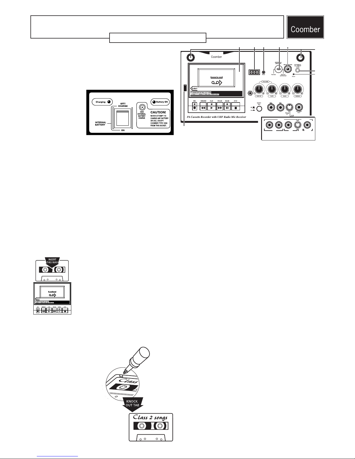
The Mains ON/OFF switch is found on the side panel. A red power light (8),
on the top panel, will illuminate when the supply is switched on.
It is good practice to ensure that the INPUT VOLUME and TAPE VOLUME
controls are turned to minimum before switching on or when connecting
microphones.
Internal Rechargeable
Battery (Optional)
Models labelled with the
suffix /R incorporate a
rechargeable battery and
charger circuit allowing the
portable PA to be used away
from a mains power source.
A side panel controls battery
use and charging.
If fully charged, the Battery OK light will illuminate when the INTERNAL
BATTERY switch is turned on. If the Battery OK light flashes, the battery
requires charging.
To charge the battery, simply plug the 2060/R into the wall and turn on the
Mains ON/OFF switch - the POWER light (8) will illuminate on the top panel.
Ensure that the INTERNAL BATTERY switch is turned to OFF/CHARGE posi-
tion. The Charging light will illuminate, and will extinguish only when the
battery is fully charged.
• To maximise battery life, never let the battery become fully discharged.
Recharge it as soon as the Battery OK lamp begins flashing.
• The battery panel also incorporates a Roka connector, allowing one
external Coomber 1959 battery to be recharged at a time.
External D.C. Input Socket (7)
A standard Roka connector allows the equipment to operate from an external DC supply of between 12 and 24 volts. The red "Power" light (8) below
the socket will illuminate only if the polarity is correct. Always disconnect
the DC source when not in use.
• The Coomber 1959 rechargeable battery and Coomber 1958 battery
charger can be used with the 2060 range.
Playing a Pre-recorded Tape
Open the cassette door with the EJECT key (9) and
insert a pre-recorded tape. Close the door and
press the PLAY key. Adjust TAPE VOLUME, BASS
and TREBLE controls to suit. To pause the tape,
press the PAUSE key.
CASSETTE INCORRECTLY LOADED WARNING! If all
three indicator lights flash five times, then the cassette may be loaded incorrectly. Without using
undue force, eject the tape and re-insert it before
trying to play the tape.
CASSETTE JAMMED! Turning off the PA while the cassette is still engaged
may cause the mechanism to jam. To remove the cassette, re-connect to the
power supply and switch on. The cassette mechanism will reset itself and
the tape can then be removed.
Valuable Recording Protection
You can protect valuable recordings by knocking out
the safety tab on the top left hand edge of a cassette. Once removed, the tape cannot be
recorded over (on that side only).
• If the RECORD key on the cassette
mechanism cannot be depressed
and the record indicator light
flashes three times, check that
the left-hand safety tab on the
top edge of your cassette has not
been removed to protect an original
recording.
• If you do wish to re-use the cassette for
recording, replace the missing tab with self
adhesive tape.
Logic Controlled Solenoid
Cassette Mechanism (1)
The cassette mechanism offers ‘one touch’ record, cue and review facilities,
and includes full Autostop - disengaging the drive automatically when the
tape reaches its end. For optimum performance it is important to keep the
pinch wheel and heads clean. If in doubt about cleaning consult your audio
visual advisor or visit the PRODUCT SUPPORT section of our website.
The solenoid controlled mechanism offers some useful features.
• The ability to switch directly between REWIND, FAST FORWARD and
PLAY without needing to select STOP first.
• CUE and REVIEW, selected by pressing FAST FORWARD or REWIND
while in PLAY mode, allows the user to fast forward or rewind the tape
by a few seconds.
TIP: Holding the key down allows the tape to go forwards or backwards
for as long as the key is depressed. AS SOON AS THE KEY IS RELEASED
THE TAPE WILL BEGIN PLAYING AGAIN.
• To record, press the RECORD key, followed by the PLAY key.
• EJECT (9) will only operate in the STOP and PAUSE modes. While the
tape is moving, the EJECT button remains locked and cannot be used.
This prevents damage to the cassette and the mechanism.
• NORMAL / CHROME TYPE TAPE. The mechanism will recognise which
type of tape is inserted and selects Normal or Chrome mode as
required, providing optimum performance at all times.
• SEARCH facility looks for a gap of 3 seconds or more, allowing the user
to wind forwards or backwards to the start or finish of a music track
(for example).
To engage, select PLAY and then depress the PLAY key for a second
time. The PLAY LED will flash twice while the cassette continues to play.
Pressing either the FAST FORWARD or REWIND keys will now initiate
SEARCH mode.
To deselect the SEARCH mode, depress the PLAY key again. The PLAY
LED will flash once.
SEARCH mode is also cancelled when the tape reaches the end, or the
STOP button is depressed.
CUE and REVIEW will not operate in the SEARCH mode.
• AUTOMATIC LEVEL CONTROL (ALC). The record level is adjusted and set
automatically to provide optimum performance from the AUX or
MICROPHONE inputs.
You may find that a small amount of distortion is heard at the start of
a recording, especially if the signal to be recorded is strong (loud). ALC
attunes itself to the general level of sound in a room - so for the best
recordings, allow the ALC to settle before recording commences. To do
this, press the PAUSE key followed by the RECORD key. The ALC will
monitor the sound levels and set itself. Release the PAUSE key after a
few seconds monitoring to start the recording.
• Reset the turns counter (2) to zero using the reset button (3) whenever
you wish to be able to return to the start of a particular passage.
0 50 100
050100
AUX
TAPE
EXT AMP
INPUTS
OUTPUTS
MIC
1 23 45
6
7
8
9
Top panel: radio mic models
Top panel inputs and outputs
non-radio mic models
Page 2
Microphone Input Sockets
All models incorporate two 6.35mm microphone input sockets.
Set the INPUT VOLUME to minimum before connecting microphones, then
adjust INPUT VOLUME, BASS and TREBLE to suit. Two mics may be used
together effectively providing they have similar characteristics.
ACOUSTIC FEEDBACK
ACOUSTIC FEEDBACK will occur when the microphone picks up sound
from the loudspeaker. This is usually due to the INPUT VOLUME being
too high, and/or the microphone being too near the equipment.
1. Make sure the microphone is switched off before switching the system on.
2. Ensure that the INPUT VOLUME is turned (anti-clockwise) to its lowest
position.
3. Switch on the microphone.
4. Gradually turn up the INPUT VOLUME until feedback just starts to occur
(you should hear a whine noise) and then turn the volume down a little
until you can no longer hear the feedback. You might have to experiment
with the volume control to get optimum results.
Note: Some microphones are not designed for use with PA systems
and further advice may be needed. Coomber 1918 or 1808 mics are ideal
for public address use.
Auxiliary Input Socket(s)
All non-radio mic models incorporate a 6.35mm and 5 pin DIN socket. Radio
mic models include only the 5 pin DIN Auxiliary input socket.
These sockets allow connection from a keyboard or other external source such as an amplifier output, portable CD or mini-disc player.
• Both mic and aux inputs can be used at the same time allowing passive
mixing between mic and aux inputs.
Recordings may be made by pressing the RECORD button. The position of
INPUT VOLUME, BASS and TREBLE controls will not affect the recording which is automatically set.
A Coomber 1974 patch lead allows connection to a CD player/mini disc via
the 5 pin DIN aux socket).
Output Socket(s)
The EXTERNAL AMPLIFIER socket provides low level mixed output. Ideal for
use with Coomber booster speakers (2185 or 2186).
The 5 pin DIN socket offers a line level output for cassette playback only.
External Loudspeaker Socket (4)
External speaker (Coomber model 411) can be connected via this socket.
The socket connection is reversible. Connecting the speaker plug to the left
and centre pin disconnects the internal loudspeaker. All sound will be
diverted to the extension speaker.
Connecting to the centre and right pin leaves the internal speaker will
remain connected. Both speakers will be equally powered, distributing the
sound output over a greater distance.
Headphone Socket (5)
Connecting Mono or Stereo headphone automatically disconnects the
internal loudspeaker. For safety you are advised to use only 600 ohm headphones (i.e Coomber 1929 stereo headphones).
Variable Speed (Optional)
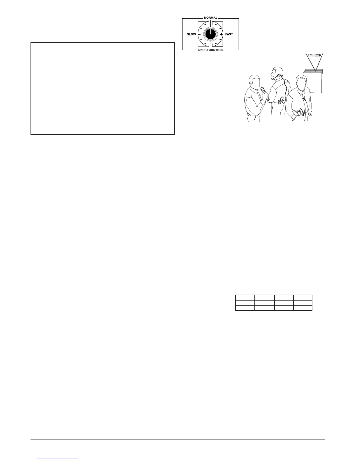
Models labelled with the suffix /V are fitted
with a variable speed control for the cassette mechanism. The dial varies the speed
of playback from -25% to +10%.
During recording, the speed control is automatically overridden.
Radio Microphone
Receiver (Optional)
Models labelled with the suffix
/W are fitted with a radio
microphone receiver board and
twin aerials.
A compatible radio microphone is required. Its frequency
must match the frequency of
the radio receiver and is shown
on the product label attached
to the rear of the equipment.
Using the 1985 Handheld radio microphone
1. Extend both aerials (6) on the 2060/W fully and pull them away from
each other.
2. Switch on the 1985 handheld radio microphone using the switch fitted in
the base. A red indicator will glow, showing that the microphone
is operating correctly.
If the light does not glow, check the condition of the battery and replace
if necessary.
3. Depress the radio microphone switch on the top panel of the 2060/W and
adjust volume to suit.
Using the 1939 Lapel or 1941 Headband radio microphone
and 1986 Bodypack transmitter
The lapel and headband microphones both use a bodypack in which a
transmitter is fitted. Ensure that the microphone and aerial are connected
to the bodypack before use.
1. Extend both aerials (6) on the 2060/W fully.
2. Switch on the the bodypack. A red indicator will glow showing that the
transmitter is operating correctly.
If the light does not glow, check the condition of the bodypack battery
and replace if necessary.
3. Depress the radio mic switch on the top panel of the 2060 and adjust volume
to suit.
Interference: Good Practice
It is always possible to pick up interference from nearby radio transmitters
while the radio microphone receiver is switched on but unused - especially
if the radio mic itself is switched off. It is therefore good practice to switch
off the radio microphone receiver, if the radio mic is not being used.
Power ratings Model 240v 12v 24v
2020 11w 3w 14w
2060 30w 10w 37w
Ratings quoted in Watts RMS using 4 ohm load.
Coomber Electronic Equipment Ltd.
Brindley Road, Warndon, Worcester, WR4 9FB, U.K.
SAFETY & GENERAL INFORMATION
Headphones: For personal safety and comfort connect headphones into equipment, turn
volume down and then switch on before placing headphones over ears. For safety use only 600
ohm headphones (i.e Coomber type 1929).
Environments: The equipment should not be exposed to dust, moisture, water, chlorine and
other corrosive substances in normal use or during storage. It will cause damage to this equipment.
Swimming pool atmospheres: are very hostile to all electro-mechanical equipment (e.g. steel
rusts and rubber perishes). Equipment returned for repairs showing evidence of use in adverse
environments may, at our discretion, be charged for even during the 12 month warranty period.
• Rechargeable battery replacement must be carried out by a competent qualified technician.
• The disposal of batteries (rechargeable or otherwise) where used in Coomber equipment
should be discarded in accordance with local regulations.
• Do not cover the ventilation openings with any items (e.g. newspaper, fabrics etc.)
• Naked flames, such as lighted candles, should not be placed on or near the apparatus.
• The apparatus should not be exposed to dripping or splashing. No objects filled with
liquids, such as vases, should be placed on or near the apparatus.
European Safety Standard: All Coomber equipment complies with EN60065. Any local
requirements for use of this equipment should be taken into account.
Class I construction: This equipment must be EARTHED.
Mains Voltage
UK & EEC: 220-240V 50Hz: Mains Cable: Line - Brown, Neutral - Blue, Earth - Yellow & Green
USA: 110-120V 60Hz: Mains Cable: Line - Black, Neutral - White, Earth - Green
Isolate from mains supply when not in use by removing the plug from the wall socket.
Mains Plug:
The mains cable fitted to this equipment is already provided with a moulded plug. If
another plug type is required, follow instructions from the plug manufacturer, or seek advice
from a qualified person. DISPOSE OF ORIGINAL PLUG SAFELY. DO NOT RE-USE.
Mains Plug fuse rating: 3Amp to BS1362 (applicable in UK)
Model type and rating information is located on a label on the rear of the product.
Additional Technical Information:
If you require any further help or information, or if
any point is not clear, then please telephone 01905 25168/9 quoting your model number and
serial number (located on a label on the rear of the product). Our Technical Department will
be pleased to help you.
Note: This equipment contains no user serviceable parts and should only be disassembled and
reassembled by competent qualified personnel. Dismantling will render the warranty void.
Electrical Safety Testing:
• Safety testing and servicing should only be carried out by competent qualified personnel.
• When undertaking an earth bond safety test, only use the externally exposed metalwork.
Do not test against internal metal components found inside tape mechanisms or CD trays THIS WILL LEAD TO IRREPARABLE INTERNAL DAMAGE.
• The supply cable is part of a special assembly. If damaged the equipment should be
returned to Coomber Electronic Equipment Limited or their agent for cable replacement.
2060 Instructions © Coomber Electronic Equipment Ltd. 2006 OPS 2060 R8 29_11_2007
• Coomber reserve the right to change
products and specifications without notice.
• All Coomber equipment is covered by a
12 months warranty against defective
components or faulty manufacture from date
of dispatch. Any modifications to or misuse of
the equipment renders this warranty void.
• Equipment that is security marked or
damaged cannot under any circumstances
be exchanged.
 Loading...