

Page 1
Cooltrax Asia Pacific Pty Ltd
138b Thistlethwaite Street, South Melbourne VIC 3205
Phone: +61 3 9686 6011 Fax: +61 3 9686 9022
ABN: 42 083 280 040
Version 4.4 One Way Interface Jan 2013
Page 2

UMD V3 Installation Manual - Remote Control 13 November 2018
Page 2 of 39
Table of Contents:
Table of Contents: ................................................................................................................................................... 2
UMD Installation V3: With Remote Control ........................................................................................................... 3
Standard System Kit of Parts: ......................................................................................................................... 3
Maintenance Box Kit: ...................................................................................................................................... 4
Third Party Protocol Upgrade Components: .................................................................................................. 4
Hardware Installation Instructions Key Points: .................................................................................................. 5
Considerations When Installing or Servicing a Cooltrax Unit: ............................................................................ 6
UMD Installation Initial Setup: .......................................................................................................................... 7
First Step – Install Antenna’s: ............................................................................................................................. 7
RF Antenna: ......................................................................................................................................................... 8
RF Antenna Installation – Physical Location Inside the Trailer: ...................................................................... 9
Low Profile Perspex Backed RF Antenna. ..................................................................................................... 10
Installing the UMD ............................................................................................................................................ 11
The Fridge Interface Cable: ........................................................................................................................... 12
Carrier Controller Setup .................................................................................................................................... 13
Powering Up the System for the First Time: ..................................................................................................... 14
Diagnostic Tests: ............................................................................................................................................... 15
Wireless Tag Installation: .................................................................................................................................. 16
Post Installation: ........................................................................................................................................... 20
Specifications: ....................................................................................................................................................... 21
FCC Compliance: ........................................................................................................................................... 23
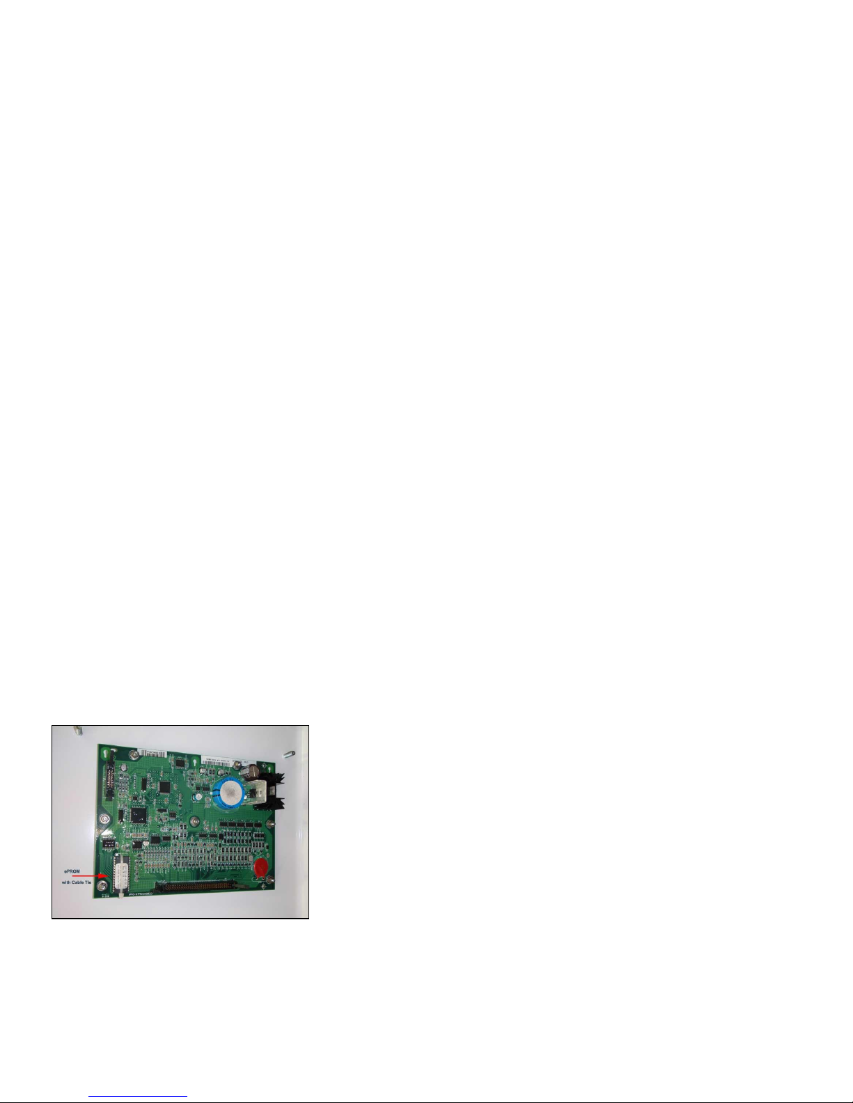
APPENDIX A: Upgrading a Carrier ePROM Chip .................................................................................................... 24
APPENDIX B: Conditions for Making a Warranty Claim ........................................................................................ 25
APPENDIX C: Installation Flow Chart .................................................................................................................... 26
APPENDIX D: Trouble-Shooting Tips and Tricks .................................................................................................... 27
APPENDIX E: Reversing the Wiring Between Serial and Data Ports ..................................................................... 31
APPENDIX F: SUPRA 850/950 INSTALLATION ....................................................................................................... 34
UMD Location: .............................................................................................................................................. 34
Antenna Location .......................................................................................................................................... 35
Fridge Interface Cable: .................................................................................................................................. 36
Page 3

UMD V3 Installation Manual - Remote Control 13 November 2018
Page 3 of 39
Power Cable Connection: .............................................................................................................................. 36
APPENDIX G: INSTALLATION ADVICE .................................................................................................................... 38
UMD Installation V3: With Remote Control
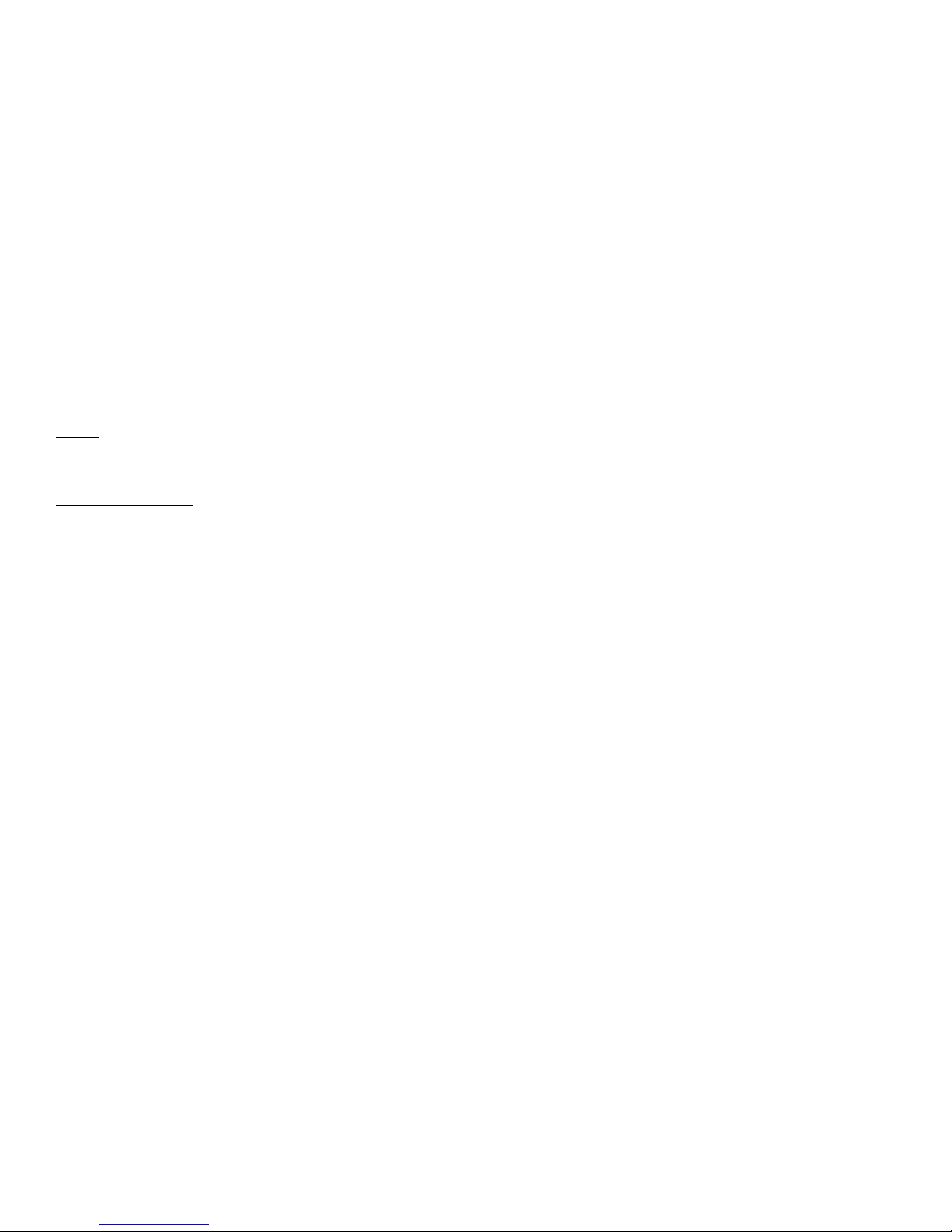
Standard System Kit of Parts:
1. Universal Monitoring Device (UMD).
2. 3G/GSM Antenna
3. GPS Antenna
4. RF Temperature Tags – if required by the customer
5. RF Door Tag and Magnet – if required by the customer
6. RF Low Profile Antenna
7. 3m Carrier Interface Cable
8. One 1.5M UMD Power Cable.
9. Mounting Plate for UMD - optional
Page 4
UMD V3 Installation Manual - Remote Control 13 November 2018
Page 4 of 39
Maintenance Box Kit:
1. Maintenance Box
2. Maintenance Box Harness
3. Reset Switch
Please note that the V3 UMD and Maintenance Box will be supplied with a specially made installation plate.
This plate has been designed to be easily mounted on the reefer frame for both X2500 and Vector reefer units.
Third Party Protocol Upgrade Components:
With the Carrier Fridge interface the following additional components are required.
1. Carrier ePROM for fridge units with Standard Controller
2. Data Card Option for fridge units with an Advanced Controller
Note: Check the controller type of the fridge to which the UMD is being installed as Standard Controllers
require an ePROM and Advanced Controllers require a Datacard download to enable 3rd party Protocols.
EPROM Revisions:
1. Standard Controller One way only - Revision 3.32
2. Standard Controller with 2-Way Remote Control capability - Revision 3.38
3. Standard Controller Multi-temp - Revision 4.12
Picture 1: UMD System Kit
Page 5
UMD V3 Installation Manual - Remote Control 13 November 2018
Page 5 of 39
Hardware Installation Instructions Key Points:
The following Hardware Installation Instructions must be read in conjunction with the detailed information
that follows in the Cooltrax Hardware Installation Manual. The “Hardware” refers specifically to the Cooltrax
UMD and Wireless Tags.
NOTE: Failure to comply with these instructions will void the Hardware warranty.
1) The Hardware must be positioned:
a) in a suitable location where it is not directly exposed to outside weather elements;
b) where it is not directly exposed to any water or other liquids including water emissions from the
internal workings of refrigeration unit;
c) where it is not directly exposed to excessive heat, dirt or grease;
d) in a horizontal alignment where the UMD the LTW connectors are at the top
2) All cables must be:
a) enclosed in split tubing up to 150mm from the connectors at each end of the cable;
b) kept away from heat sources;
c) of sufficient length so that there is no tension or kinking applied to the cables.
3) All connectors must be locked into place and tested to ensure they will not come loose.
a) For the UMD the LTW black connectors with locking sleeve require a quarter-turn
4) Fixing screws are supplied with the UMD. Do not drill out mounting holes for larger screws as this may
pierce the internal seal and will void warranty.
Page 6
UMD V3 Installation Manual - Remote Control 13 November 2018
Page 6 of 39
5) All installations must be fully validated by Cooltrax Support before the asset leaves the installation
location. Cooltrax will not be liable for costs incurred through the asset being recalled for validation at
a later time.
6) No Cooltrax Hardware or component is to be replaced without consultation and agreement from a
Cooltrax support staff member.
7) Hardware must not be opened outside of the Cooltrax Office.
Considerations When Installing or Servicing a Cooltrax Unit:
Temperature Increases Within the Trailer :
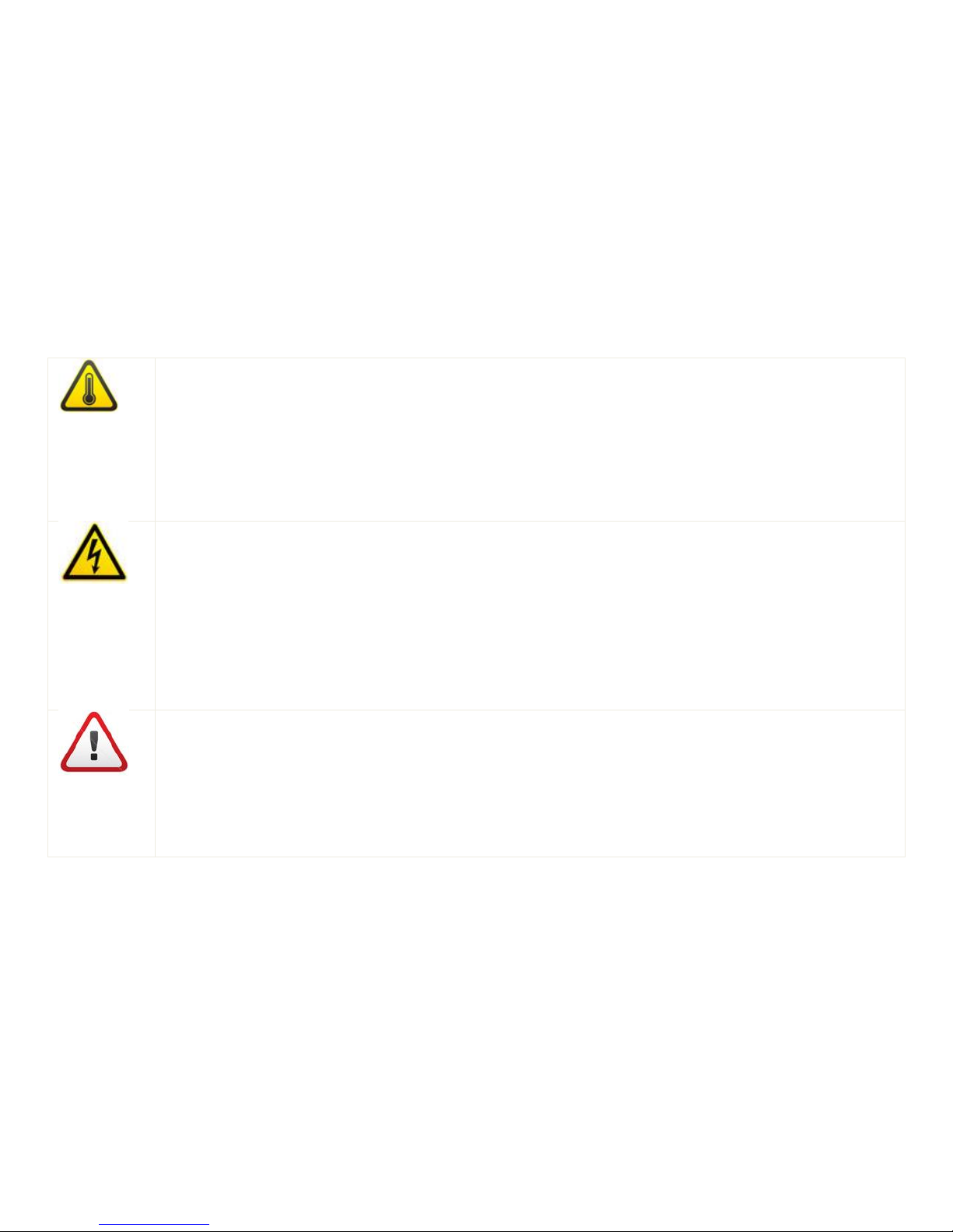
The Reefer unit MUST be turned off when installing or conducting maintenance on A Cooltrax
Unit, this will lead to increased temperatures within the trailer and if the trailer is loaded the
goods may be damaged. Always give due consideration to the temperature within the trailer,
Cooltrax will not be held responsible for any spoiled contents.
Warning Risk of Electrical Shock:
Always remove the battery cable from the negative terminal followed by the cable from the
positive terminal prior to commencing an installation or service of Cooltrax hardware. There is
danger of exposure to high electrical energy during installation procedures highlighted in this
manual and a risk of shock or injury. Only trained Technical staff should install service or
maintain Cooltrax hardware.
DANGER: Risk of Personal Injury.
This unit can be remote controlled. The unit may START and STOP at any time by remote
command. Prior to performing any maintenance to the unit, place the Maintenance Toggle
Switch (located on the Cooltrax Maintenance Box) to the MAINT MODE position to disable the
remote starting capability.
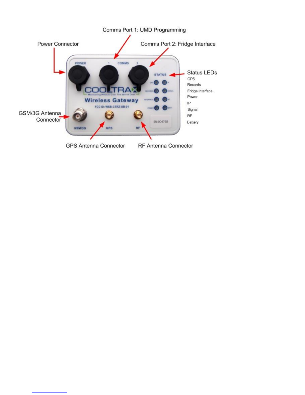
Picture 2: UMD Connections.
Page 7
UMD V3 Installation Manual - Remote Control 13 November 2018
Page 7 of 39
UMD Installation
Initial Setup:
1. Open the front engine bay access doors
2. Open LH compartment access door to the fridge battery
3. Turn OFF the main switch on the side or front of the Carrier Controller cabinet
4. Disconnect Carrier Refrigeration System Battery.
First Step – Install Antenna’s:
GSM and GPS Antennas:
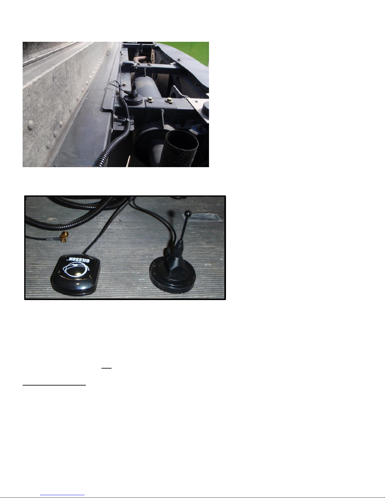
1. Locate the GSM and GPS Antennas on top of the carrier system painter steel frame as pictured below.
The base of each antenna is magnetic and they can be attached directly to the steel frame. Run a bead
of Sigaflex or a similar adhesive product around the base of the antenna to ensure that it won’t come
free with vibration.
2. Locate the antennas as pictured to ensure maximum separation between the two devices to deliver
optimal performance.
3. From the top side insert the antenna cables in split tubing and feed through the hole in the fridge
frame
4. Retrieve the cables from the hole lower down the frame just above the battery compartment close to
where the UMD Gateway unit will be installed.
5. Cable tie the co-axial cables to the Carrier system’s wiring harness or fixed hardware that does not get
hot.
6. Loop and secure the excess co-axial cable in the reefer cavity and connect and finger tighten the co-
axial connectors to the UMD.
Picture 4: GSM/GPS Antenna Location
Page 8
UMD V3 Installation Manual - Remote Control 13 November 2018
Page 8 of 39
Antennas Located on Top Rail
GPS and GSM Antennas:
RF Antenna:
The RF antenna should be mounted inside the refrigerated trailer (the “box”) for optimal results when
receiving data from RF temperature or door tags located within the trailer. If the customer configuration is for
fridge interface only with NO internal RF Tags then the Antenna is not required.
Internal RF Antenna:
1. Drill a small pilot hole through the firewall and ensure the loom and hardware clearance from the
engine bay side is adequate.
2. If OK, enlarge the hole to 20mm and remove any drill swarf from both sides of the firewall
3. Feed the cable into split tubing up to 150mm from the connectors at each end of the cable
4. Feed the mounting plate onto the RF Antenna Cable and tighten into place using the supplied
lock-nut.
5. Feed the length of antenna cable into 20mm convoluted tubing for protection
Page 9
UMD V3 Installation Manual - Remote Control 13 November 2018
Page 9 of 39
6. From inside the trailer feed the connector end of the RF Antenna through the prepared hole
leaving sufficient cable to reach the preferred mounting location inside the trailer.
7. Loop and secure the excess co-axial cable in the cavity and connect and finger tighten the co-axial
RF connector to the UMD
8. Cable tie the antenna cable to existing cabling or components that do not get hot near the
firewall hole and up the evaporator cavity.
9. When connecting the RF antenna cable to the UMD ensure there is sufficient length available so
that there is no tension or kinking applied to the cable at the connection point.
Avoid routing the cables any closer than three inches of pipes, valves (plumbing) or parts of the
engine that become hot during reefer operation.
RF Antenna Installation – Physical Location Inside the Trailer:
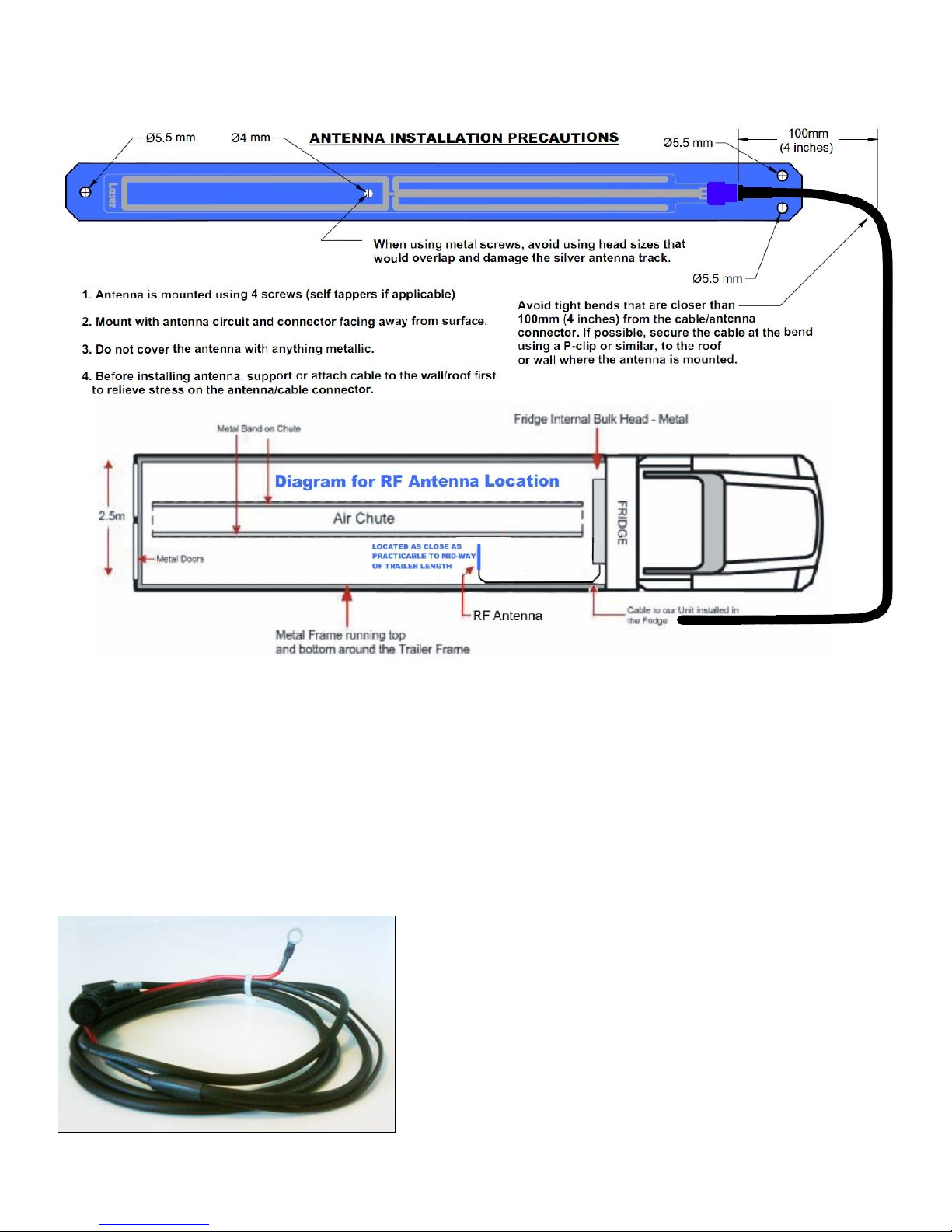
For optimal results the antenna should be mounted to the roof of the trailer in a horizontal position. Ensure
that the antenna is located out from the back wall as far as possible but where it is still protected from
damage by the internal bulkhead of the fridge unit – this provides the best opportunity for the antenna to
communicate consistently with any tags located inside the trailer.
Wherever possible the RF Antenna should be located 300mm away from any steel such as fridge supports,
internal bulk-heads etc
Use P-Clips to tidy up excess cabling and fasten to the internal wall.
Important – Recommended Antenna
The UMD is designed and certified to work with the recommended antenna 2J model 2J6A41BG. Use with any
other antenna could adversely affect the electromagnetic emission characteristics and will violate the terms of
certification and require retesting.
Page 10
UMD V3 Installation Manual - Remote Control 13 November 2018
Page 10 of 39
Low Profile Perspex Backed RF Antenna.
UMD Power Cable:
The Cooltrax Power Cable comes complete with a 3A in-line fuse. The cable is 1.5M long and has a 6-Pin
connector at one end and eye-connectors at the other.
Fuse
Recommended replacement fuse is ATC-3 automotive 3A blade fuse from Bussmann, or equivalent.
Picture 7: Cooltrax Power Cable
Page 11
UMD V3 Installation Manual - Remote Control 13 November 2018
Page 11 of 39
Cooltrax Power Cable
1. Power Cable Battery Connections
a. Locate the red wire on the battery cable assembly. This lead, with in-line fuse and eye terminal,
should be added to the leads coming from the Carrier system’s battery positive (+VE) terminal.
b. Locate the black wire on the battery cable assembly. This lead, with eye terminal, should be added
to the leads coming from the Carrier system’s battery negative (-VE) terminal.
2. Thread the power cable UMD connector up from the battery area to the UMD.
3. Use cable ties to ensure that the wires leading to and from the fuse holder are not subjected to strain or
tension that could cause the wires to be pulled from the fuse holder.
4. NOTE: Sufficient amounts of slack must be maintained to prevent possible disconnection, or damage to
the wires and fuse holder. In addition, care must be taken to mount the fuse holder in a position that will
allow it to be easily accessed in the event that future servicing is required.
5. DO NOT CONNECT TO THE UMD at this time but leave enough cable in the area of the UMD so that there
will be no tension on the cable when it is connected.
6. Coil and tie down any excess Power Cable Length in the UMD area.
7. Cable tie the UMD Power cable from the UMD area down to the battery area onto the existing wiring
harness or fixed hardware - keep away from any sources of excessive heat.
8. When connecting the Power cable to the UMD ensure there is sufficient length available so that there is no
tension or kinking applied to the cable at the connection point.
Note: Continuous power can also be taken from the Starter Motor rather than from the battery.
Note: Enclose the cable in split tubing up to 150mm from the connectors at each end of the cable
Avoid routing the cables any closer than three inches of pipes, valves (plumbing) or parts of the
engine that become hot during reefer operation.
Installing the UMD
1) The UMD must be positioned:
a) in a suitable location where it is not directly exposed to outside weather elements;
b) where it is not directly exposed to any water or other liquids including water emissions from the
internal workings of refrigeration unit;
c) where it is not directly exposed to excessive heat, dirt or grease;
2) The connection sequence for any of the UMD connectors to their associated cables is common :
a) Ensure that the number of circuits in the cable connector matches the number of circuits of the
connector on the UMD.
b) Align the cable end groove in the cable connector body to the ridge in the connector on the UMD.
c) Push the cable connector fully into the UMD connector receptacle.
d) Rotate the cable connector locking ring clockwise while pushing it gently towards the UMD. When
the locking ring aligns with the connector bayonet coupling the ring will go forward.
Page 12
UMD V3 Installation Manual - Remote Control 13 November 2018
Page 12 of 39
e) Continue to rotate the locking ring a further quarter turn where the ring will come up against the
stops.
f) To disconnect the cable, rotate the connector locking ring one quarter turn anti-clockwise and pull
the connector directly away from the UMD panel. Pull only on the connector body. Never pull on
the cable.
i) in a suitable location where it is not directly exposed to outside weather elements;
ii) where it is not directly exposed to any water or other liquids including water emissions from the
internal workings of refrigeration unit;
iii) where it is not directly exposed to excessive heat, dirt or grease;
Note: If the supplied mounting plate is being used then attach the V3 UMD to the mounting plate using self
tapper screws or rivets.
• The UMD the LTW connectors are at the top
Note: Enclose all cables in split tubing up to 150mm from the connectors at each end of the cable
Avoid routing the Cable Harness any closer than three inches of pipes, valves (plumbing) or parts of
the engine that become hot during reefer operation.
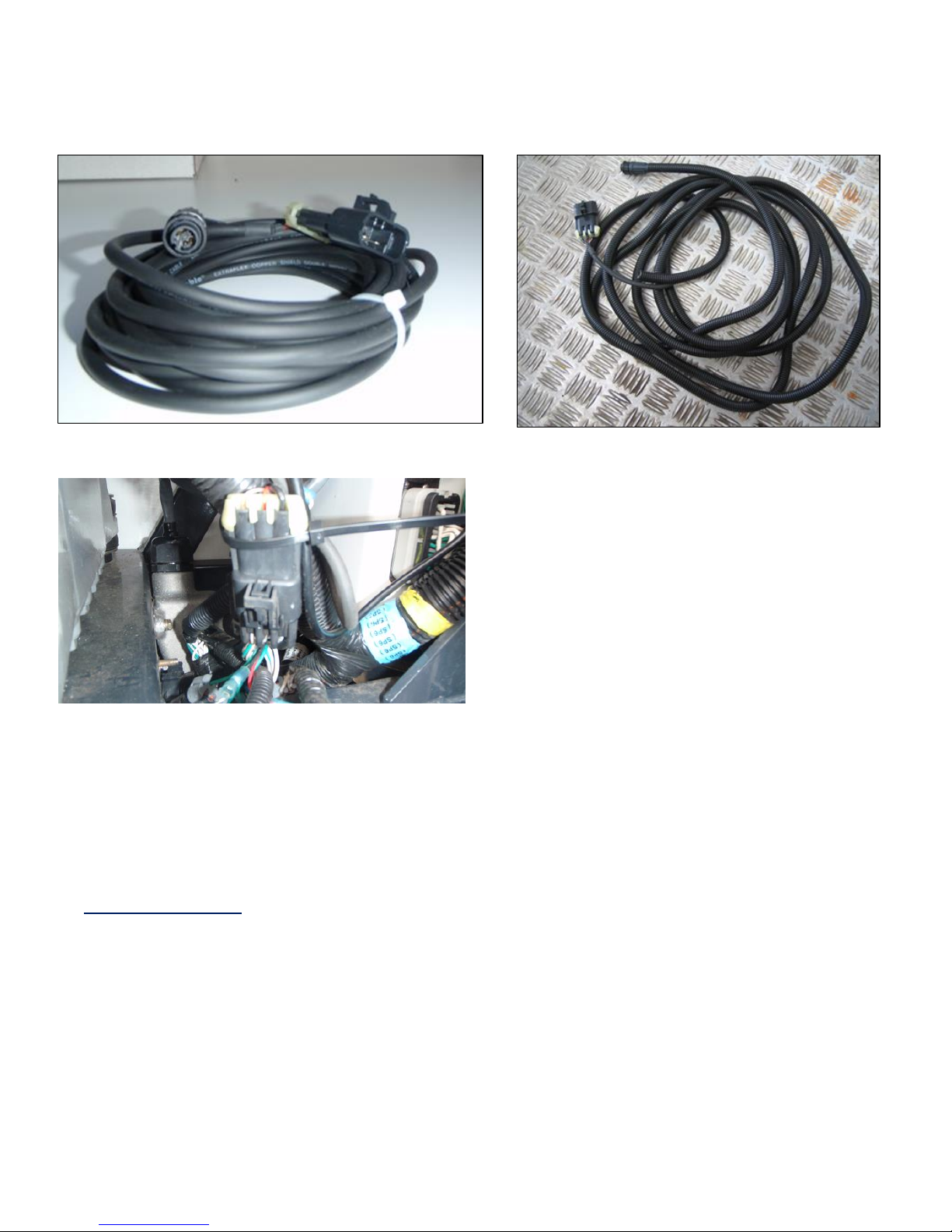
The Fridge Interface Cable:
The Fridge Interface cable connects to the 4-Pin Panel COM2 Connector located on the UMD Gateway.
The other end of the cable is a 3-Pin Carrier Plug which connects to the Carrier Serial Port, a 3 Way flat plug
located in the cable loom behind the controller box. The cable must be run from the UMD on the LHS of the
refrigeration system to the Serial Port Plug’s location underneath the controller on the RHS of the refrigeration
system. The cable should be well supported and protected from damage from hot components and sharp
edges. Ensure there is enough free cable length at each end to provide tension free connections.
1. Connect the interface cable to the Carrier system’s Serial Port Plug.
2. Ensure the contacts are fully inserted, and the connector shells are locked.
3. Unplug the dust cap on the UMD COM Port 2 connector
4. Connect the Fridge Interface Cable to the Panel Connector on the UMD
5. Cable Tie and Tidy up. Be careful to keep the cables away from any excessive heat source.
6. Note: When connecting the interface cable ensure there is sufficient length available so that there is no
tension or kinking applied to the cable at the connection point.
7. Note: Enclose the cable in split tubing up to 150mm from the connectors at each end of the cable
Page 13
UMD V3 Installation Manual - Remote Control 13 November 2018
Page 13 of 39
Picture 10: Interface Cable
Cooltrax supplied Interface Cable
Interface Cable fed into Split tubing
Interface Plug connected to Serial Port on Reefer
Carrier Controller Setup
There are at least two different types Carrier Control systems which can interface with the UMD. This
installation procedure does not cover the detail of the installation or setup requirements of the Carrier
equipment; however it outlines the general requirements for the known Controller types
Standard Controller:
1. The Standard controller requires the fitting of an EPROM Revision 3.32 and above to be fitted before
the interface will be functional – this revision has the DataTrak Communication Option. Revision 3.34
also has this option. For detailed instructions on upgrading and ePROM see Appendix at the end of the
manual.
2. For a Standard Controller with 2-Way capability enabled an EPROM with Revision of 3.38 is required.
3. For a Standard Controller on a multi-Temp reefer with 2-Way capability enabled an EPROM with
Revision of 4.12 is required
Page 14
UMD V3 Installation Manual - Remote Control 13 November 2018
Page 14 of 39
Advanced Controller:
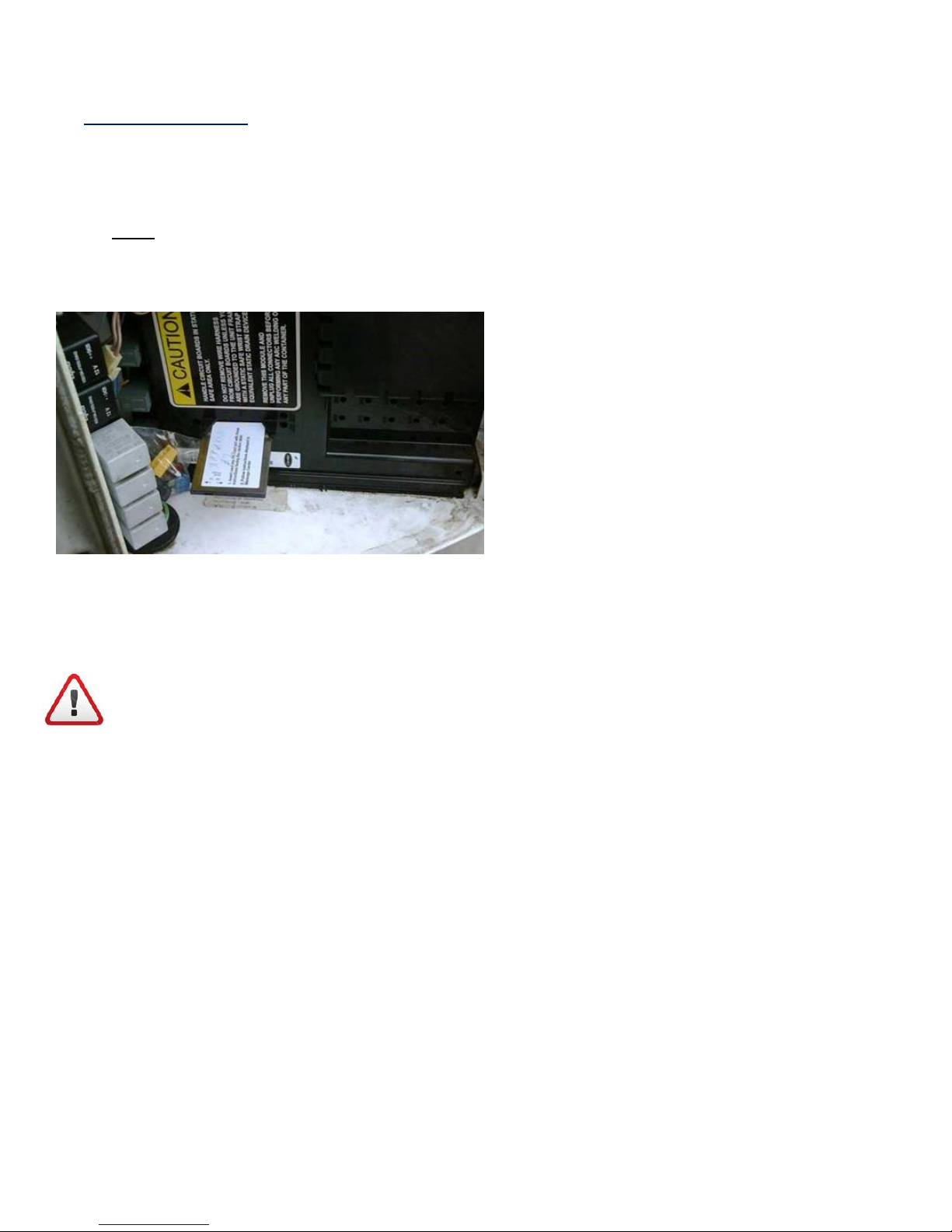
1. The Advance controller requires the ‘Third Party Protocol’ to be programmed into the controller using
a ‘Data Configuration Card’. The controller is then enabled using the ‘Reefer Manager’ PC application.
Scroll through the options and set the ‘Communications Protocol’ to ‘OTHER’.
2. Note: Minimum Firmware Revision for the Micro should be: 04.12
Picture 11: Carrier Datacard in Controller PCMCIA Slot
Powering Up the System for the First Time:
After all hardware and wiring is installed, power may be connected to the Cooltrax System for the first time.
IMPORTANT NOTE:
Verify that all cable and individual wiring connections are properly connected and weather-sealed before
reconnecting the cable to the positive terminal first and then to the negative terminal of the reefer battery.
Once the cables to the positive and negative terminals of the refrigerated battery are connected, the UMD will
commence its power up sequence.
Boot-Up Sequence:
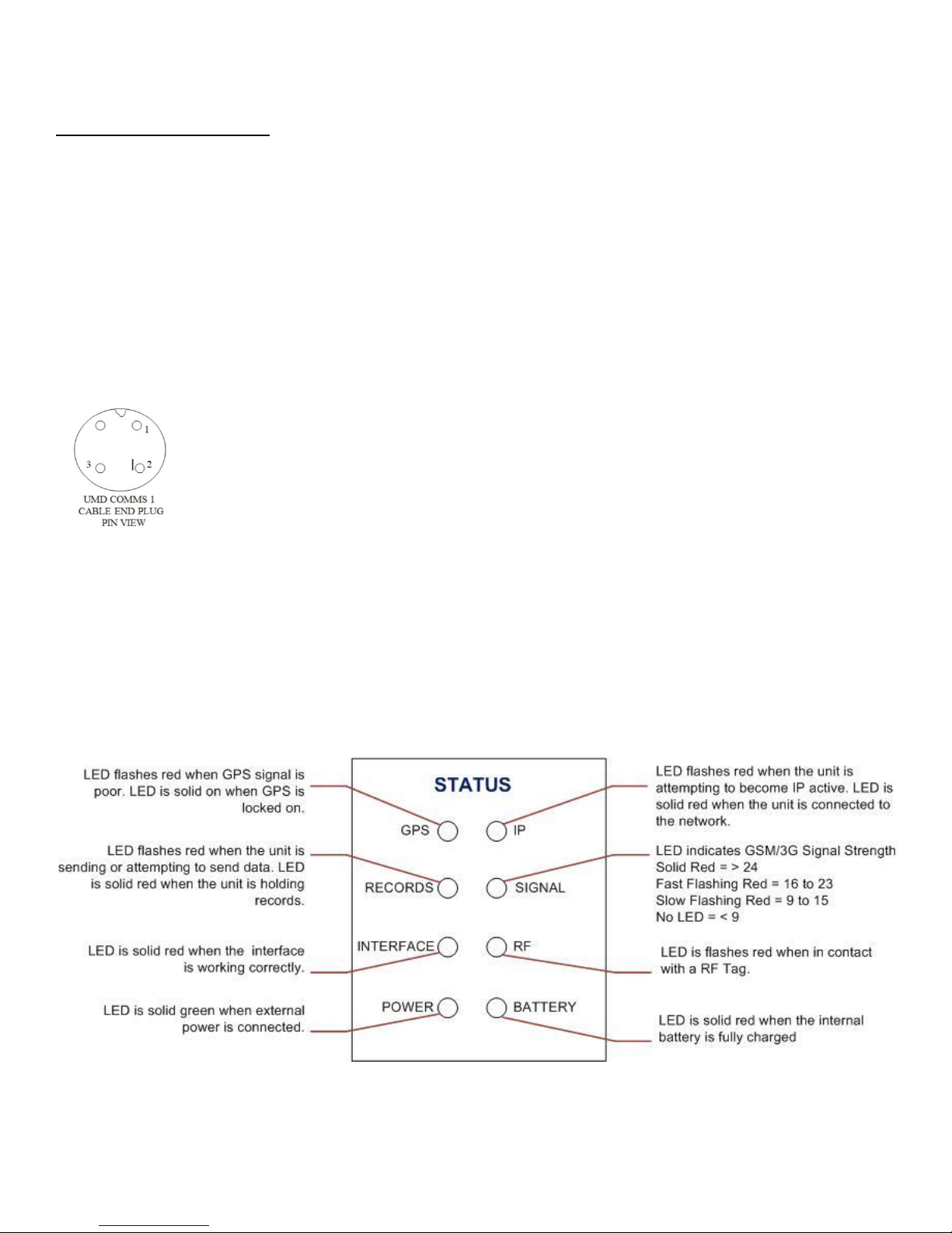
1. Within approximately 30 seconds the UMD ‘Power’ LED will light up GREEN, followed closely by the
battery light.
2. Shortly after the Signal LED will begin to flash, assuming that there is GPRS or 3G service available on
the GSM/3G network.
3. The IP LED will at first flash and then remain in a constant ON State once an IP connection has been
established
4. The GPS LED will light up a constant RED to indicate that GPS has been acquired – typically in 30 secs
or less.
5. If RF Tags have been installed then the RF LED will flash every few seconds as the tags communicate
with the RF Reader section of the UMD
Page 15
UMD V3 Installation Manual - Remote Control 13 November 2018
Page 15 of 39
Diagnostic Tests:
Testing the Fridge Interface:
After the UMD / Carrier Fridge interface cable is connected to the 3 way flat connector in the Carrier fridge
loom, with the fridge OFF, measure the resistance between the chassis (0V) and Pin 3 of the plug that will
connect into the UMD COM2 Port. This should be <10 ohms. If this is not correct, check the wiring of the Flat
Carrier loom plug back to the Fridge Controller. Turn the fridge ON and measure the voltage between the
chassis (0V) (negative of meter) and Pin 2 of the plug that will connect into the UMD COM2 Port. This should
be –8 to –10V DC. If this is not correct, check the voltage on Pin 1 of the same plug. If that is –8 to –10V DC
then the wiring to pins A & B of the carrier flat loom plug need to be swapped and the measurement re-taken.
If there is no voltage present on either pins 2 or 1, check the connections from the Carrier loom flat plug back
to the fridge controller.
Picture 12: Cooltrax Interface Plug
If these two measurements are correct, connect the fridge interface cable to the UMD COM2 Port and power
ON the UMD (If not already ON).
If the Fridge cable was connected to a UMD that was OFF and then powered ON after the connection was
made, the UMD should sense the fridge within a couple of minutes and the fridge light on the UMD should
come ON RED.
Picture 12: UMD LED’s
System Test:
1. Check the Engine Bay for any tools, fixings or off-cuts, which may have been left behind.
Page 16
UMD V3 Installation Manual - Remote Control 13 November 2018
Page 16 of 39
2. Install and re-connect Carrier System Battery
3. Un-plug the UMD ‘POWER’ connector dust-cap and connect the UMD Power lead.
4. Within approximately 30 seconds the UMD ‘Power’ LED will light up GREEN, followed closely by the
battery light. Within a few minutes, assuming that there is GPRS or 3G service available on the
GSM/3G network, after the Signal LED will begin to flash.
5. Turn ON the Carrier Controller using the main 12V ON/OFF switch and be prepared for the
refrigeration system to start.
Please Note: Always connect the power to the UMD last!
Wireless Tag Installation:
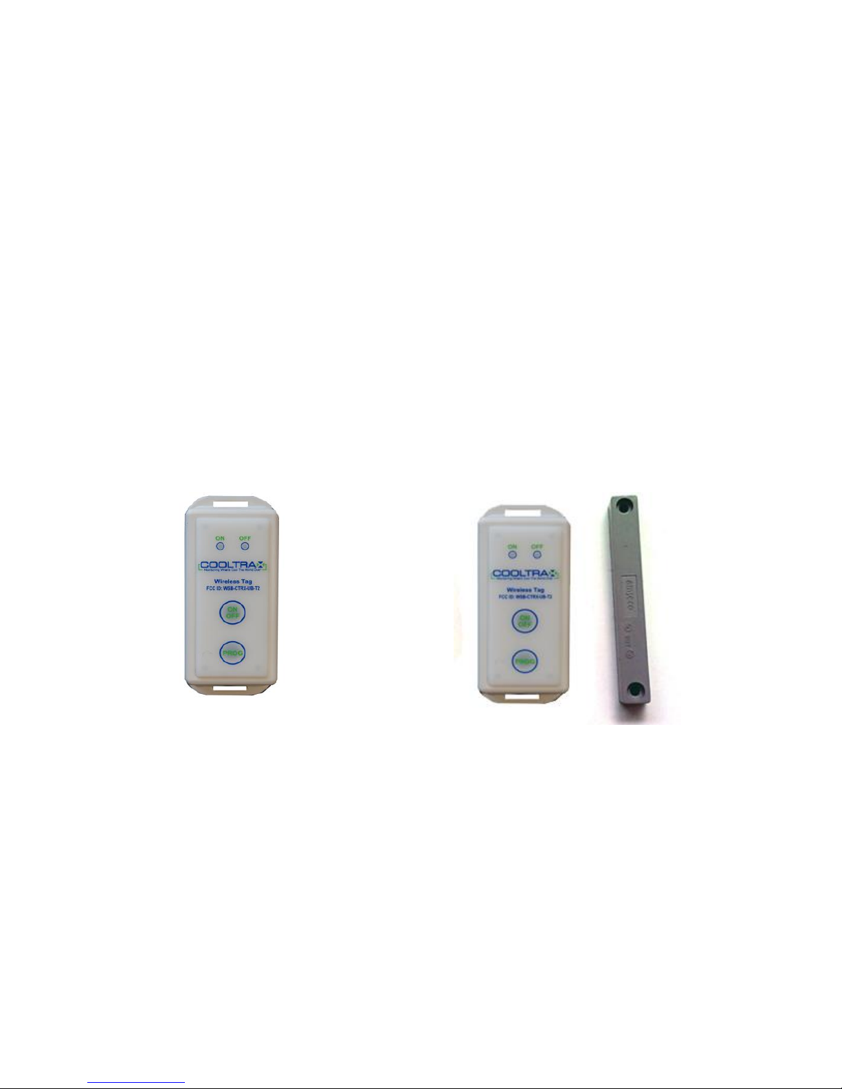
The new RFID UMD communicates with CoolTrax remote temperature and door sensors via wireless; this
saves considerable installation time. Depending on the customers desire to have independent temperature
reading points in the trailer or a door open and close tag and magnet, CoolTrax provides RF capable tags which
communicate with our UMD, these tags should located by the installer according to the customer’s
requirements.
Picture 13: Wireless Temperature and Door Tags
Wireless Temperature Tag
Wireless Door Tag and Magnet
Cooltrax Wireless Temperature Tag:
Each CoolTrax Tag has a flanged base with holes to allow the installer to either screw or pop-rivet the tag to
the trailer wall or door. Double-sided tape is another mounting option for flexibility and ease in moving
around to different monitoring locations within the trailer.
Check with Cooltrax or the customer for information in respect to where the tags should be located in each
trailer.
Page 17
UMD V3 Installation Manual - Remote Control 13 November 2018
Page 17 of 39
Important Note: The RFID Tags supplied with a UMD are specific for that particular UMD they must be kept
with and installed with the specific UMD. If RF Tags from another UMD Kit are installed they will not be able to
report to that UMD.
Temperature and Door Tags need to be located in a position within the trailer where they will not be damaged
in the trailers normal daily operations – by fork-lifts when loading pallets etc.
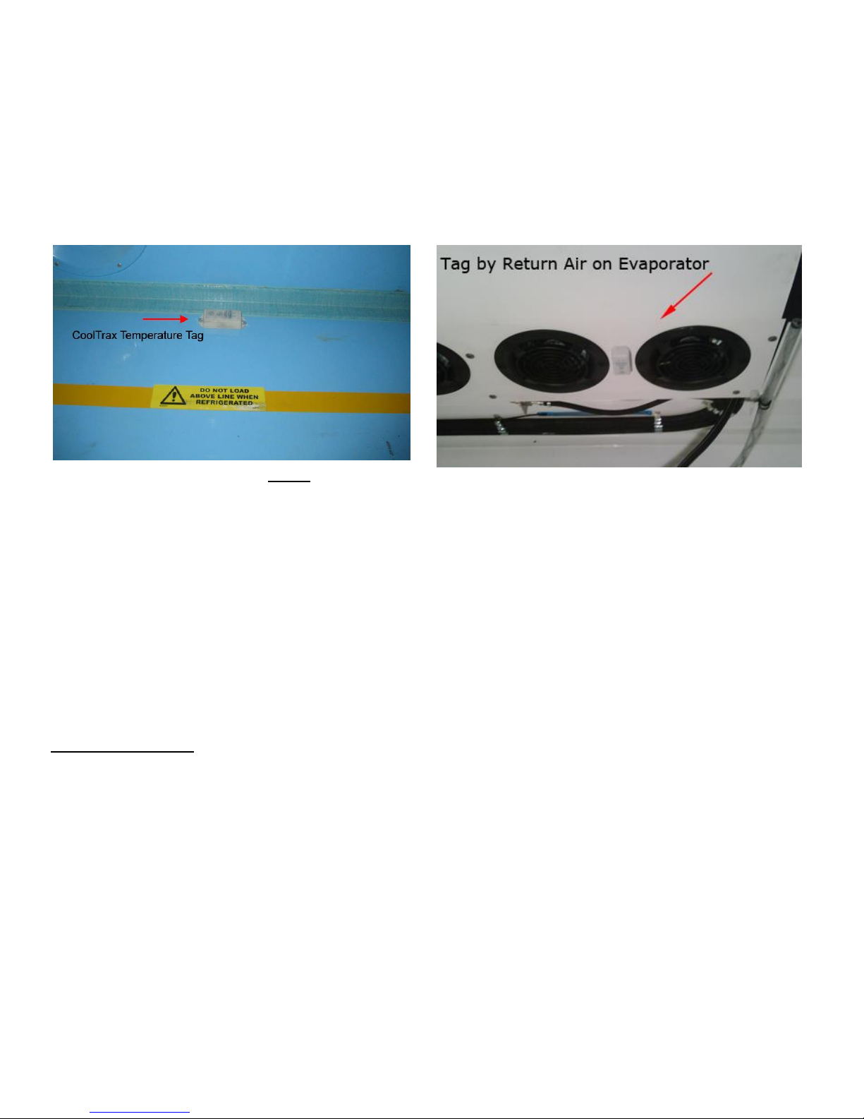
Picture 14: Wireless Temperature Tags Locations
Temperature Tag located above the load
line along the trailer wall.
Temperature Tag located next to the Return Air duct
Cooltrax Wireless Door Tag:
The location of the Door Tags and Magnet will vary according to the various body types of the trailer and
whether the fitted doors are roller or barn style. The important consideration, again, is to locate the Tag and
Magnet in a position where they will not be damaged. This requires a careful assessment by the installer on a
case by case basis as there are so many variations from trailer to trailer and even between the different door
types.
Cooltrax provides brackets for both types of door installation.
Installation Options:
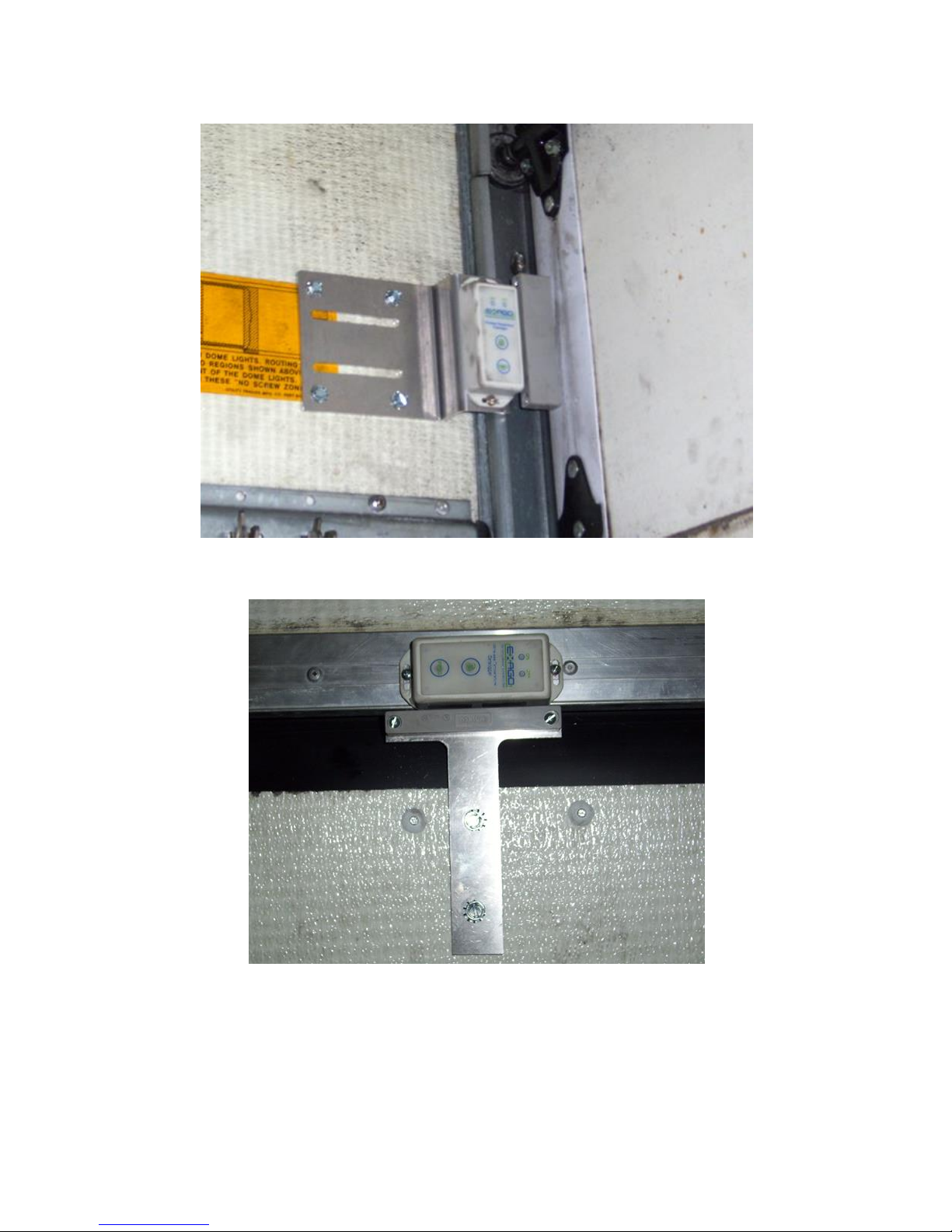
1. On the Inside of the Barn doors with the magnet located on the RH door (looking from inside the trailer
out
2. If the Trailer body has a lip along the top at the rear then the tag can be located on the inside of that lip
where it is protected and the magnet attached to a bracket on the inside of the door
3. In the case of a roller type door the tag is typically located on the inside LH side wall directly adjacent
to the roller door and the magnet and spacer is located on the roller door itself – checking for
clearance when the door is “rolled up”. See picture below
Page 18
UMD V3 Installation Manual - Remote Control 13 November 2018
Page 18 of 39
Picture 15: Wireless Door Tags
Door Tag fitted to a Roller Door Installation
Door Tag and Magnet fitted to Barn or Side Door
Page 19
UMD V3 Installation Manual - Remote Control 13 November 2018
Page 19 of 39
Door Tag Installation Considerations:
Tag Alignment with the Magnet:
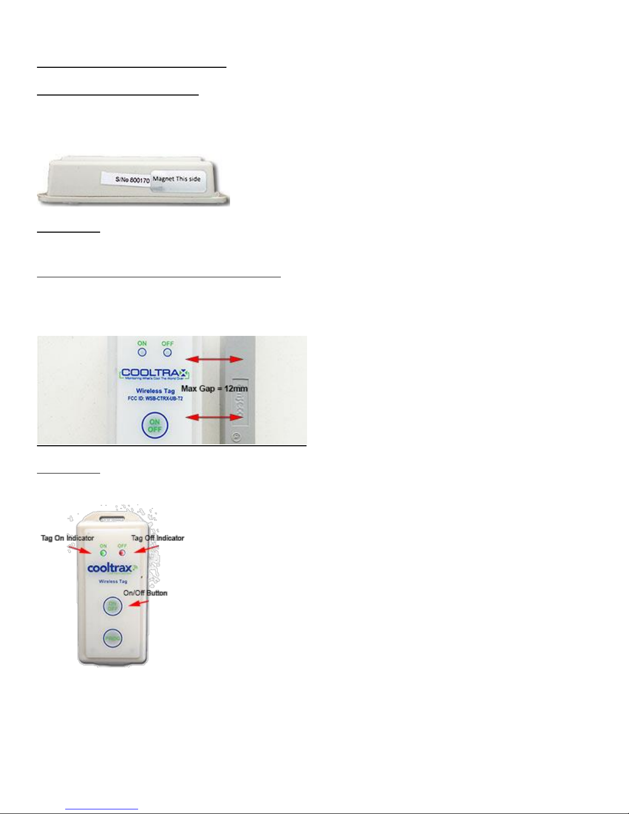
On the side of the door tag is a label “Magnet This Side”, make sure that the door tag is installed with this side
of the tag facing the magnet.
Please Note: The magnet should be vertically aligned mid-way with the side of the door tag where possible –
this may require packing the magnet up.
Distance between the Door Tag and the Magnet:
Install the door tag with a maximum of 12mm between the tag and the magnet to ensure consistent
communication.
Please Note: Make sure that the Door Tag is switched on by holding down the on/off button on the tag and
checking that the green On LED flashes to indicate an On State.
Page 20

UMD V3 Installation Manual - Remote Control 13 November 2018
Page 20 of 39
Post Installation:
Once the physical installation of the unit is complete and the UMD is powered on contact CoolTrax Support
staff so that they can check that the unit is reporting as expected.
On contact provide the following Installation Details (via phone or fax the completed Installer Template
provided by CoolTrax):
1. The Customer Name
2. The Fleet ID of the Trailer
3. The UMD ID (located on the front of the UMD – typically UCXXXX
4. The Fridge Model
5. The Sensor location with Sensor ID – if fitted
6. The installer name and contact details – mobile phone number to call once the unit has been tested
Please ensure that CoolTrax staff confirms that the unit is reporting data as expected BEFORE the trailer leaves
the installers premises. Cooltrax will not be liable for costs incurred through the asset being recalled for
validation at a later time.
CoolTrax staff will ask you to conduct a number of fridge operations as part of the Installation Check to make
sure the unit fridge interface is correctly installed and configured.
• Power the fridge unit on and off to check the Fridge Interface is functioning as expected
• Change Set Point Temperature
• Open and Close the Rear Door to test Door Tag if fitted.
• Send some Remote Commands to ensure the Interface is working correctly
• Switch to Maintenance Mode to ensure that the Maintenance Box is connected correctly
CoolTrax Support Contacts:
Support – (613) 9686 6011
Email: [email protected]
Page 21
UMD V3 Installation Manual - Remote Control 13 November 2018
Page 21 of 39
Specifications:
UMD Power
Power Supply
12VDC to 24VDC
Average Power Consumption
Less than 2W
Internal Fuse
2A (not field replaceable)
Discrete
Type
Closing contact
No of Channels
2
WiFi Interface
Band
430 MHz UHF ISM
Transmit Power
10 dBm Max Burst Transmission
Receive Sensitivity
-100 dBm typical
Range
50m typical in clear line of sight
Serial Data Comms
Comm 1
RS-232
Data Rate
9600 Baud Standard configurable up to 38.4K Baud
by firmware
Function
Typical use for fridge interface
Comm 2
RS-232
Data Rate
9600 Baud Standard configurable up to 38.4K Baud
by firmware
Function
Typical use for firmware
upgrades
GPS
Specifications subject to
available / visible satellites
Acquisition Time
Power Up
< 1min typical
Re-acquisition
< 1 sec typical
Accuracy
Horizontal
< 2.5 meters CEP
Enclosure Dimensions
Length
160mm
Width
120 mm
Height
55 mm
Min height clearance
120 mm
Page 22
UMD V3 Installation Manual - Remote Control 13 November 2018
Page 22 of 39
Mounting Centers
(4 by 5.0mm slot holes in base
flanges)
Mountable in any attitude
Length
150 mm
Width
110 mm
Environmental Specifications
Sealing
IP65
Operational Temperature
-30C to +35C (external)
RF Tag Specifications:
Tag Power
Internal battery
3.6V lithium thionyl chloride
Average Power Consumption
Less than 70 uW
Expected Life
< 3 years
Range and Accuracy
Temp measurement accuracy
±0.50C by calculation
Temp range
-300C to +700C
Stabilization period
4 hrs typical
Sample Rates and
Temperature Data Storage
Sample send rate (temp mode)
20 secs average
Sample rate (consignment mode)
1 min to 4 hrs in 1 min increments
Temp data storage capacity
(consignment mode)
31,488 samples
Temp data upload rate
400 samples per sec
Range
50m typical in clear line of sight
WiFi Interface
Band
430 MHz UHF ISM
Transmit Power
10 dBm Max Burst Transmission
Receive Sensitivity
-100 dBm typical
Range
50 m typical in clear line of sight
Enclosure Dimensions
Length
97 mm
Width
40 mm
Height
22 mm
Page 23
UMD V3 Installation Manual - Remote Control 13 November 2018
Page 23 of 39
Mounting Centers
(2 by 3.5mm by 13mm slot holes in
base flanges)
Mountable in any attitude
subject to antenna requirements
Environmental Specifications
Sealing
Wet assembled
Operational Temperature
-30C to +70C (external)
Compliance and Safety
FCC Compliance:
Note: This equipment has been tested and found to comply with the limits for a Class A digital device, pursuant to part 15
of the FCC Rules. These limits are designed to provide reasonable protection against harmful interference when the
equipment is operated in a commercial environment. This equipment generates, uses, and can radiate radio frequency
energy and, if not installed and used in accordance with the instruction manual, may cause harmful interference to radio
communications. Operation of this equipment in a residential area is likely to cause harmful interference in which case the
user will be required to correct the interference at his own expense.
Modifications not expressly approved by the manufacturer could void the user's authority to operated the equipment under
FCC rules.
CAUTION
RISK OF EXPLOSION IF BATTERY IS REPLACED BY AN INCORRECT TYPE.
DISPOSE OF USED BATTERIES ACCORDING TO THE INTRUCTIONS.
Function of Cellular Component
The UMD reports to the server approximately once every 15 minutes on the LTE or 3G mobile carrier
networks, transferring close to 100 kB of data per day.
In the US and Canada, model WG-V3-LTE-NA, the UMD uses a ublox TOBY-R202, communicating on LTE bands
2, 4, 5 and 12, as well as UMTS bands 850 and 1900.
In the APAC region, including Australia and New Zealand, model WG-V3-LTE-AP, the UMD uses ublox TOBYL280, operating in LTE bands 1, 3, 5, 7, 8, and 28, as well as UMTS hands 850/900 and 1900/2100.
Page 24
UMD V3 Installation Manual - Remote Control 13 November 2018
Page 24 of 39
APPENDIX A: Upgrading a Carrier ePROM Chip
1. Start the unit and verify operation
2. Disconnect the negative battery cable
3. Locate the Micro-Processor Logic Board
a. For Trailer Units – it will be located behind the key-pad & display module or inside the control
box
b. For truck units it will be located inside the control box, on the door.
4. Connect a wrist strap to your wrist and secure the clamp onto good ground such as the bare-metal
hinge holding the micro assembly in place or other non-painted metal area.
5. Locate the ePROM, carefully cut and remove the tie-wrap, holding the ePROM in place.
6. Note the orientation of the ePROM before removing it. There is a small notch in one end that will
match up with the notch in the outline of the chip on the board. The new chip must be installed with
the notch in exactly the same position. Using the removal tool (p/n 07-00297-00) remove the chip from
the board.
7. Place the new small tie-wrap (inc in the Parts Kit) under the ePROM socket. Open the box and hold it
by both ends. Attach the installation tool (p/n 07-00298-00) on the ePROM while holding the tool with
your thumb on the silver pad (this allows the entire tool to be grounded through your hand). After
positioning the notch on the ePROM in the correct direction, carefully align the pins with the socket.
Gently push the ePROM into the socket until seated. Remove the insertion tool and closely inspect the
ePROM prongs where they entered the socket. Make certain that all of the prongs are fully inserted
into the socket and that none were bent or pushed out of the way during the insertion process. Secure
the ePROM in place with the tie-wrap and cut off excess length.
8. For REV 3.32 only – place decal onto a visible location inside the control box.
9. Secure the logic board back into place and close the control box door.
10. Start the unit and verify operation.
Note: Adjustments to hour meters, Functional Parameters and Configurations are not necessary as these
settings are contained within the logic board itself and replacing the ePROM will not effect or change their
settings.
Page 25

UMD V3 Installation Manual - Remote Control 13 November 2018
Page 25 of 39
APPENDIX B: Conditions for Making a Warranty Claim
Pursuant to the Contract of Sale (Master Agreement) you entered with Cooltrax, Cooltrax provides 12 months
warranty on all hardware in accordance with the terms and conditions of the Master Agreement. To make a
warranty claim, the customer and their installer must comply with the following:
1. Your Service Agent, who has been previously approved by Cooltrax, must call Cooltrax Support on
telephone number +61 3 9686 6011 within Support Hours, which are 09:00 to 17:00 Monday to Friday
(AEST) to interactively work through a diagnostic process on a faulty Universal Monitoring Device
(“UMD”), Maintenance Box or Tag before a UMD, Maintenance Box or Tag is removed or replaced.
2. A UMD should not be removed from your asset without approval of Cooltrax Support after an
unsuccessful attempt to repair the UMD locally or by remote diagnostics.
3. If a UMD is removed from your asset and sent back to Cooltrax without the prior approval of Cooltrax
Support then your warranty claim will not be recognized and all costs of and associated with repairs
will be charged to you.
4. If you or your approved Service Agent wishes to have a hardware issue investigated outside of normal
Cooltrax Support hours then they should refer to the Troubleshooting Section of the latest Cooltrax
Installation Manual. If the issue is not able to be resolved then you or your agent will need to contact
Cooltrax Support within normal Support Hours for further investigation and/or approval to remove the
UMD for Warranty evaluation.
5. If any Warranty Claim arising from water damage to the UMD or its connectors is to be recognized, you
must first provide Cooltrax Support with a photo of the installed location of the UMD on your asset
prior to removal.
6. Once approval for removal is given, you must return the faulty hardware to Cooltrax for evaluation of
your Warranty claim and a decision as to whether the unit can be repaired or should be replaced.
7. All costs incurred for the assessment and/or removal and delivery of the faulty device to Cooltrax are
your responsibility.
8. The Cooltrax warranty applies where the hardware failure arises from a fault in any of the electronic or
mechanical components within the hardware under normal operating conditions.
9. Cooltrax will not recognize any Warranty claim where the hardware failure does not arise from any
fault on the hardware electronic or mechanical components, including, without limitation, where:
a) the installation of the hardware has not been carried out in accordance with the Hardware
Installation Instructions and the Cooltrax Installation Manual
b) a non-approved person has installed, worked on or removed the device
c) the UMD shows evidence of an external event that has damaged the unit
d) UMD has been opened
e) UMD has been removed without the prior approval of Cooltrax Support
f) Cooltrax has not received one or more photos of the install location and the UMD prior to removal
in the event of a claim arising from water damage.
Page 26
UMD V3 Installation Manual - Remote Control 13 November 2018
Page 26 of 39
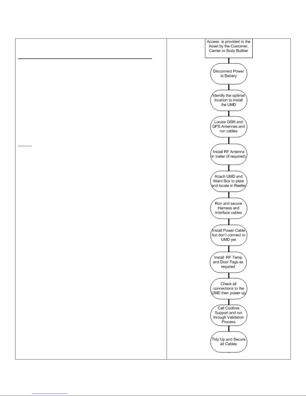
APPENDIX C: Installation Flow Chart
Installation Flow Chart for new or Retro Fit Installation:
This is the installation process for a Cooltrax System to a
Carrier Reefer. At the end of the process you will have
installed and fully validated the Cooltrax System.
Under no circumstances should the asset be released to the
fleet without being validated by the Cooltrax Support Staff.
Cooltrax will not be liable for costs incurred through the
asset being recalled for validation at a later time.
Note: To fully validate a Cooltrax install the asset should
have line of sight to the sky to ensure that the system can
gain a GPS fix on sufficient satellites.
Page 27
UMD V3 Installation Manual - Remote Control 13 November 2018
Page 27 of 39
APPENDIX D: Trouble-Shooting Tips and Tricks
Fault: No GPS Reported:
Diagnostics:
Is the GPS LED on the UMD Solid Red? If not then the GPS Engine inside the UMD is unable to get sufficient or
any GPS signal
Actions:
Move the asset to a position where the GPS antenna has clear view of the sky
Check the connector on the UMD, the GPS Antenna has a small gold connector (SMA) which connects to the
panel connector on the UMD labeled GPS. Make certain it is finger tight.
Note that the RF Panel Connector is the same connector type but labeled RF
Try a second GPS antenna if you have one, if not contact Cooltrax Support to arrange for a spare antenna.
Fault: The UMD is not reporting to the web applications – essentially the unit is offline.
Diagnostics:
How are the IP and the Signal Red LED’s behaving?
For consistent communications with the web application the GSM or 3G modem within the UMD must first
register with the Telco Provider and then become IP active - ready to communicate with the website. When
there is data to be sent, the modem connects to the website allowing a bi-directional transfer to occur
between the modem and the website via the cellular network
The Red Signal LED will flash slow, fast or solid depending upon the signal strength and the IP LED will slow at
first and then flash fast.
Note: Signal LED Flash Legend
`Slow Flashing Red – Signal Strength of 9 to 15
Fast Flashing Red – Signal Strength of 16 to 23
Solid Red - > than 23
Actions:
Move the asset to a position where the GPS antenna has clear view of the sky
Check the connector on the UMD, the GSM/3G Antenna has a larger silver connector (TNC) which connects to
the panel connector on the UMD labeled GSM/3G. Make certain it is finger tight.
Try a second GSM/3G antenna if available, if not contact Cooltrax Support to arrange for a spare antenna.
Page 28
UMD V3 Installation Manual - Remote Control 13 November 2018
Page 28 of 39
If none of these actions resolve the issue the UMD will need to be removed and sent back to Cooltrax as:
1. The SIM Card may be inactive or faulty
2. The 3G or GSM Modem within the UMD may be faulty
3. The software configuration of the unit may be corrupt
Fault: The Reefer Unit is on but we are not receiving Reefer Data
Diagnostics:
Cooltrax receives Reefer data via an interface connection between our UMD and the Reefer Serial Port.
When communications is in place between the UMD and the reefer the Interface LED on the UMD will be solid
red, if this LED is not lit then there is no interface available and corrective actions are required.
Actions:
Check the Interface cable is locked securely into place on the UMD COM2 panel connector – COM2 is the top
left connector.
Try a second Interface Cable if one is available, if not contact Cooltrax Support to arrange for a spare cable.
If the Reefer is fitted with a Carrier Standard Controller then it requires an EPROM upgrade to enable the 3rd
party Communications DATATRAK option. See instructions in Appendix A for fitting the correct Revision
EPROM – it must be 3.32 and above. Without this upgrade the Interface will not work.
If the Reefer is fitted with a Carrier Advanced Controller then the Reefer must have its Data Port opened by a
Carrier supplied DATATRAK PCMCIA Card. See instructions in Appendix A for enabling the 3rd Party Protocol
Data Port on an Advanced Reefer unit. Without this upgrade the Interface will not work.
On the Advanced Controller only you may need to select “Other” as the protocol type in the Data Menu option
on the controller.
Testing the Fridge Interface:
After the UMD / Carrier Fridge interface cable is connected to the 3 way flat connector in the Carrier fridge loom, with
the fridge OFF, measure the resistance between the chassis (0V) and Pin 3 of the plug that will connect into the UMD
Comm2 Port. This should be <10 ohms. If this is not correct, check the wiring of the Flat Carrier loom plug back to the
Fridge Controller. Turn the fridge ON and measure the voltage between the chassis (0V) (negative of meter ) and Pin 2 of
the plug that will connect into the UMD Comm2 Port. This should be –8 to –10V DC. If this is not correct, check the
voltage on Pin 1 of the same plug. If that is –8 to –10V DC then the wiring to pins A & B of the carrier flat loom plug
need to be swapped and the measurement re-taken. If there is no voltage present on either pins 2 or 1, check the
connections from the Carrier loom flat plug back to the fridge controller.
Page 29
UMD V3 Installation Manual - Remote Control 13 November 2018
Page 29 of 39
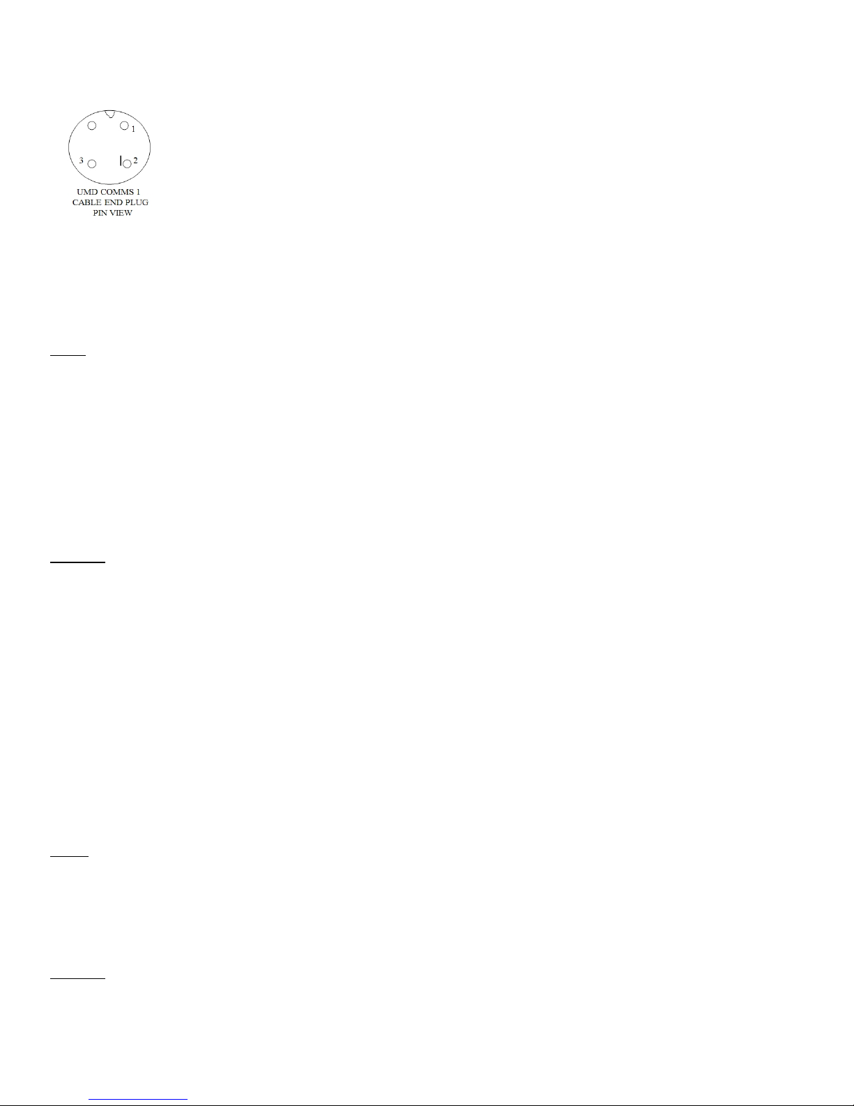
CoolTrax Interface Plug
If these two measurements are correct, connect the fridge interface cable to the UMD COMM 2 Port and power ON the
UMD (If not already ON).
If the Fridge cable was connected to a UMD that was OFF and then powered ON after the connection was made, the
UMD should sense the fridge within a couple of minutes and the fridge light on the UMD should come ON RED.
Note: the recommended firmware revision for the HDMI on Carrier Advanced Controller fridges is Revision 04.12. This
works on European Vector and American versions of the fridge and allows for remote two-way control of
each. Sometimes if the firmware is a lower revision the fridge interface can fail and an upgrade is
recommended.
Fault: The Reefer Will Not Turn On with the Local Switch
After fitting the Cooltrax System the Reefer will not turn on normally using the local On/Off Switch
Actions:
If the Reefer has a standard controller and you have upgraded the EPROM check that the EPROM is seated
correctly
Check wiring looms and make sure you haven’t accidently unplugged a cable while looking for the Serial Port
Plug which is often tucked behind the controller on older model Reefers.
Check Battery Voltage on the Reefer Battery if it is below 12.3DCV you will need to charge the battery as it will
not start the reefer at this level.
Fault: The UMD will not Power On or is running on Internal Battery
If there is no Power to the UMD the Green Power LED at the bottom LH corner of the LED array will be off.
Note: If the UMD has been previously powered up for a reasonable time it will run on internal battery for 3
hours or so (if battery is fully charged). In this case the Red Battery LED will be illuminated on the bottom RH
side of the LED array.
Actions:
Page 30
UMD V3 Installation Manual - Remote Control 13 November 2018
Page 30 of 39
Check Battery Voltage on the Reefer Battery if it is below 12.3DCV you will need to either turn on the reefer or
charge the battery as the UMD will not power on at this charge level. The UMD will switch to sleep mode at
12.3V which indicated by the Green Power LED being the only one illuminated.
Once the battery is charged up to 12.8V then the UMD will switch back into full active mode.
Check that the red wire on the UMD Power Cable is connected to the +Ve on the battery and the black to the
–Ve terminal.
Check the fuse in the inline fuse holder located on the +Ve cable
Make sure the end two-pin cable connector is tightened securely to the panel connector on the UMD labeled
Power – the top left connector on the UMD.
Try a second power cable if it is available, if not contact Cooltrax Support to arrange for a spare cable.
Fault: RF Door Tag is not Reporting
The RF Door Tags are typically mounted on the side and/or rear doors of the trailer and communicate back to
the UMD in the Reefer unit via the Low Profile RF Antenna located on the internal roof of the trailer.
Actions:
Check that the gold SMA RF Connector is connected to and tightened firmly on the RF panel connector on the
front of the UMD
Make sure that the Tag is turned On – hold down the On/Off Button if the Tag is currently on then the On LED
will flash Green rapidly if it is off then the Red Off LED will flash. To change from Off to ON continue to hold
down the On/Off Button and the Tag state will change after a few seconds.
The distance between the Tag and the Magnet can be no more than 12mm – check that the distance where it
is installed is OK. To test you could remove the magnet and hold it against the tag then move it away from the
Tag, the Red LED should flash after about 20 seconds, and then, when you bring the magnet back up to the tag
it will flash green after 20 seconds.
Make sure that the side of the tag with the label Magnet attached is facing the magnet when installed.
Make sure the Antenna is mounted with the flat blue antenna case oriented across the trailer width not
length-wise as this reduces RF capability.
Make sure that neither the Tag nor the antenna is flat against or located behind any metal obstructions.
Try another Tag or Antenna if you have one, if not contact Cooltrax Support to arrange for a spare.
Fault: RF Temperature Tag is not Reporting
Page 31

UMD V3 Installation Manual - Remote Control 13 November 2018
Page 31 of 39
Check that the gold SMA RF Connector is connected to and tightened firmly on the RF panel connector on the
front of the UMD
Make sure that the Tag is turned On – hold down the On/Off Button if the Tag is currently on then the On LED
will flash Green rapidly if it is off then the Red Off LED will flash. To change from Off to ON continue to hold
down the On/Off Button and the Tag state will change after a few seconds.
Make sure the Antenna is mounted with the flat blue antenna case oriented across the trailer width not
length-wise as this reduces RF capability
Make sure that neither the Tag nor the antenna is flat against or located behind any metal obstructions.
Try another Tag or Antenna if you have one, if not contact Cooltrax Support to arrange for a spare.
APPENDIX E: Reversing the Wiring Between Serial and Data Ports
On the European Vector model reefers and occasionally on other models we need to swap the wiring between
the round data port and the flat serial port. This is required as Cooltrax utilizes Carrier’s 3rd Party protocol for
Page 32
UMD V3 Installation Manual - Remote Control 13 November 2018
Page 32 of 39
communicating with the micro and on some reefers (always the European Vectors) only provide this
information via the round data port and not the flat serial plug.
Please refer to pin and wiring changes below:
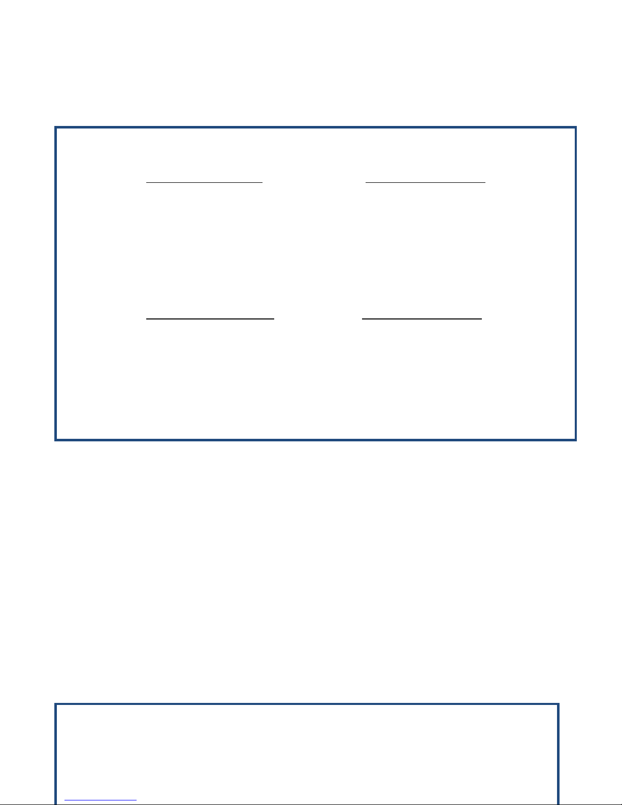
The wires of interest are CURRENTLY connected as follows:
CARRIER CONFIG PORT ADVANCE CONTROLLER
ROUND PLUG CONNECTOR 3MP PIN
A 15
B 27
C 3
STARTRAK COMMS PORT ADVANCE CONTROLLER
FLAT PLUG CONNECTOR 3MP PIN
A 29
B 17
C 5
THESE CONNECTIONS NEED TO BE SWAPPED AROUND AS FOLLOWS.
Page 33
UMD V3 Installation Manual - Remote Control 13 November 2018
Page 33 of 39
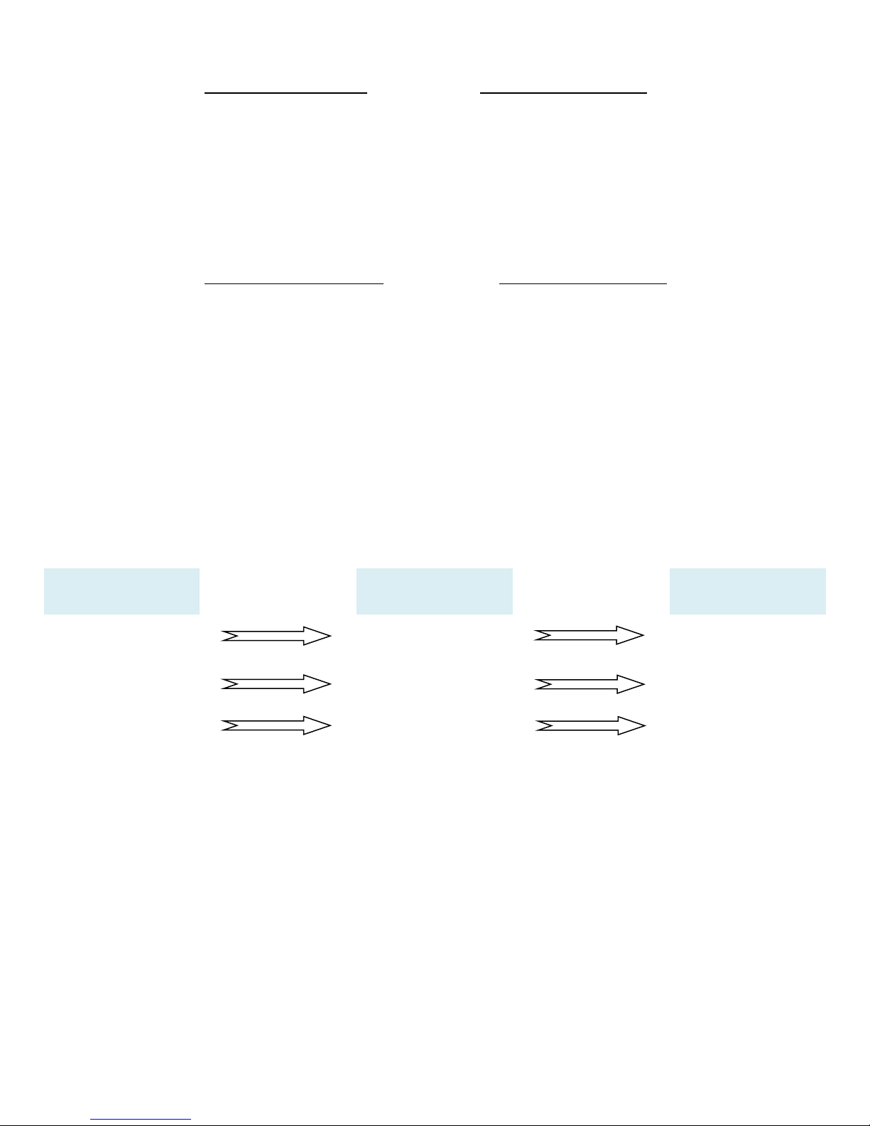
CARRIER CONFIG PORT ADVANCE CONTROLLER
ROUND PLUG CONNECTOR 3MP PIN
A 29
B 17
C 5
STARTRAK COMMS PORT ADVANCE CONTROLLER
FLAT PLUG CONNECTOR 3MP PIN
A 27
B 15
C 3
Summary of Changes:
Plug Pins
Original
New
C
3MP03
3MP05
B
3MP15
3MP17
A
3MP27
3MP29
Page 34
UMD V3 Installation Manual - Remote Control 13 November 2018
Page 34 of 39
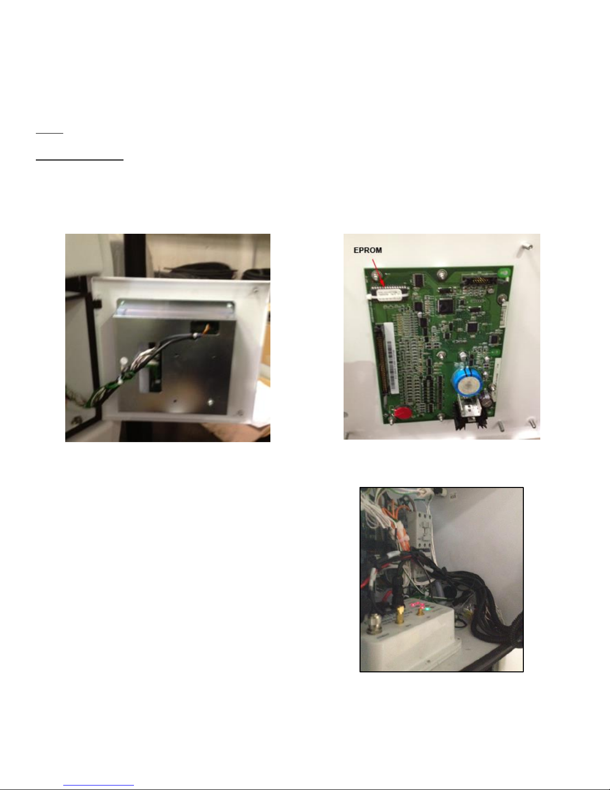
APPENDIX F: SUPRA 850/950 INSTALLATION
Installing the Cooltrax System to a SUPRA 850 or 950 on a Rigid type asset is slightly different to installing it on
Trailer type Reefers.
Note: The SUPRA will require an EPROM Upgrade - see detailed instruction in Appendix A above
EPROM Revisions:
1. Standard Controller One way only - Revision 3.32
2. Standard Controller with 2-Way Remote Control capability - Revision 3.38
3. Standard Controller Multi-temp - Revision 4.12
UMD Location:
The Cooltrax Gateway will locate easily within the
control box of the Supra with plenty of room for
cabling and antenna connections. The Gateway is
screwed to the base of the control box just in front of
the motherboard and relays.
Page 35
UMD V3 Installation Manual - Remote Control 13 November 2018
Page 35 of 39
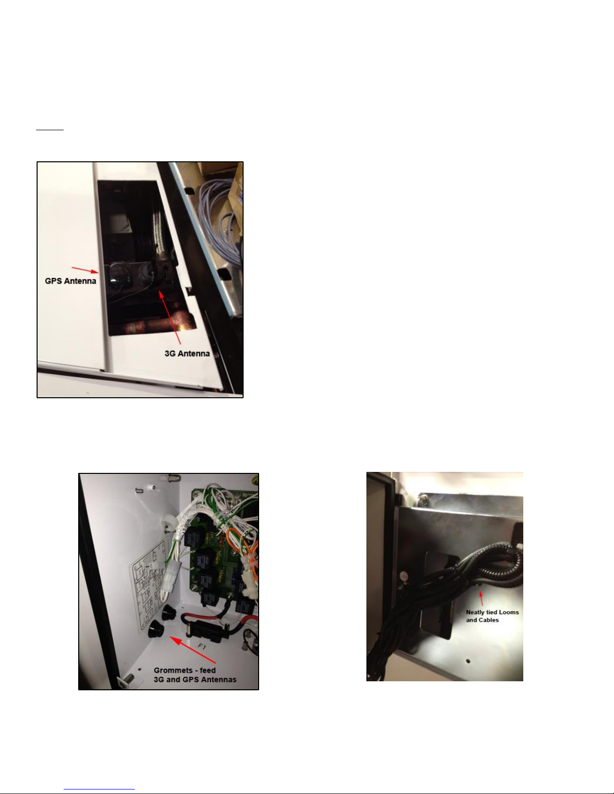
Antenna Location
The GPS and 3G Antennas are attached to the top rail of the reefer frame, their magnetic bases will hold them
in place, just run a bead of Sigaflex around the base to make sure they don't vibrate free.
Note: You may need to cut a hole out of the grill section at the top of the fridge to ensure that the GPS
antenna has clear view of the sky so that it can communicate with the minimum number of GPS Satellites.
Feed the antenna cables down through the reefer, keeping them away from heat sources and feed them into
the controller box via the spare rubber grommets in the side of the box. Cable tie the antenna cables to
existing structures or hoses and coil and tie off any excess neatly.
Page 36
UMD V3 Installation Manual - Remote Control 13 November 2018
Page 36 of 39
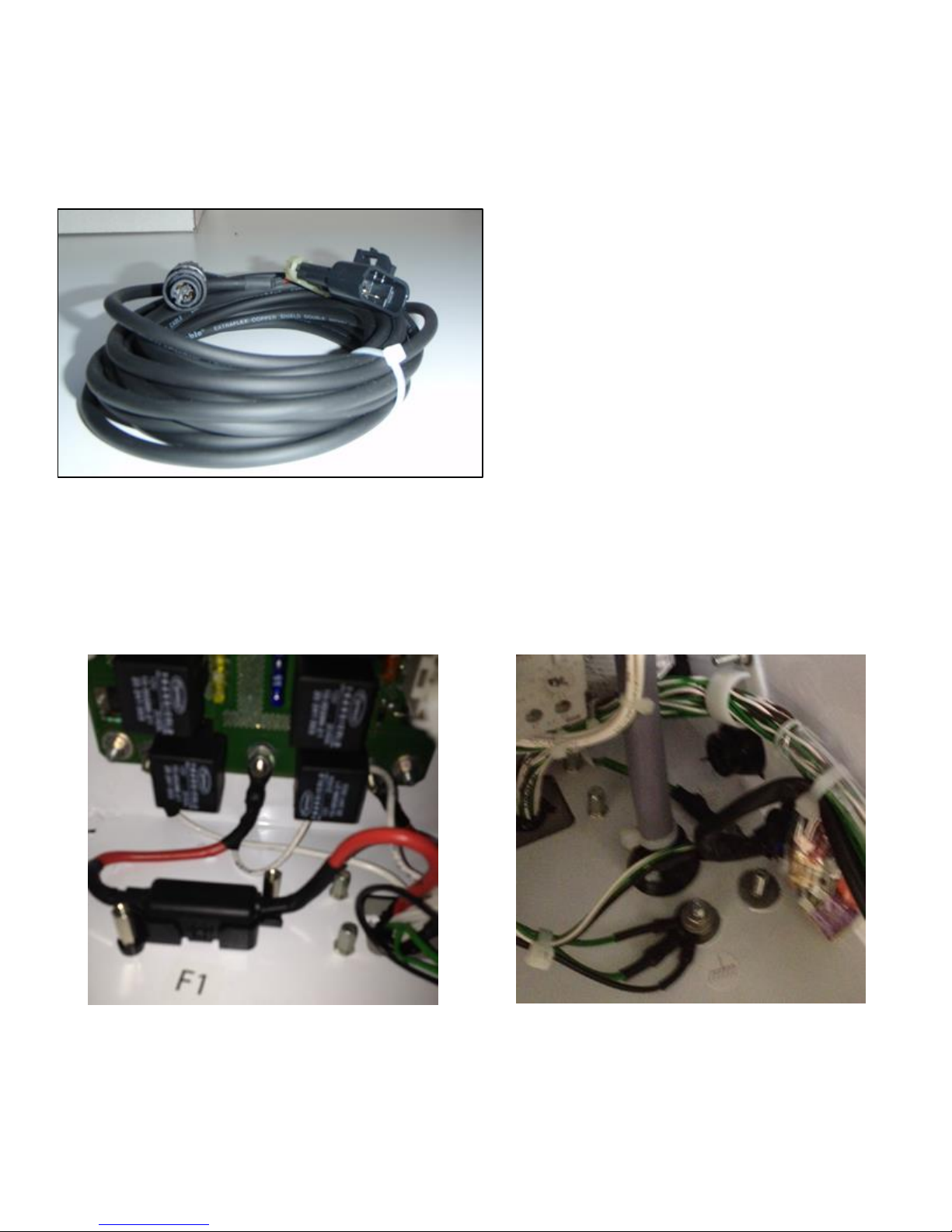
Fridge Interface Cable:
Connect the 3-Pin Delphi Plug on the Fridge Interface cable to the matching Serial Port on the Controller which
is located just below the control box. Plug the other end into the COM2 Port on the UMD, tighten down and
twist to lock in.
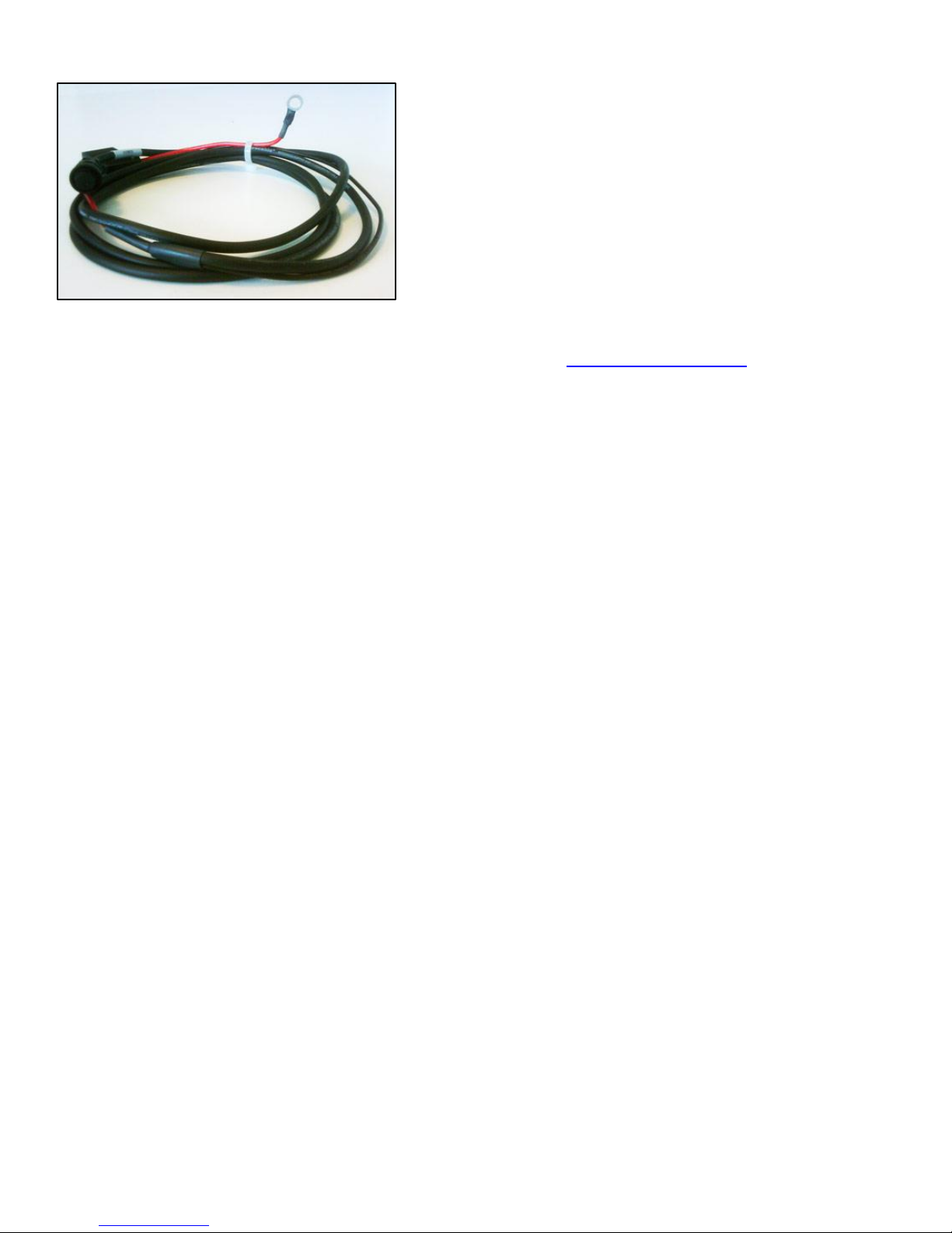
Power Cable Connection:
Once all cables and antenna connectors are in place install the power cable last of all. The Gateway should be
connected to continuous power so that the unit continues to track the asset when the fridge unit is powered
off. With the Supra Series it is convenient to take power from the positive supply side of the fuse F1 and
ground run to fridge chassis.
Fuse Holder F1 for Power Connection
Connection to Earth on Control Box
Connect the 2-Pin Power cable connector to the Cooltrax Gateway unit, twist down and lock-in place.
Page 37
UMD V3 Installation Manual - Remote Control 13 November 2018
Page 37 of 39
Do a final tidy of cables to complete the installation and call Cooltrax Support to validate that the Gateway is
reporting location and fridge information as expected. Refer to the Post Installation section above.
Page 38
UMD V3 Installation Manual - Remote Control 13 November 2018
Page 38 of 39
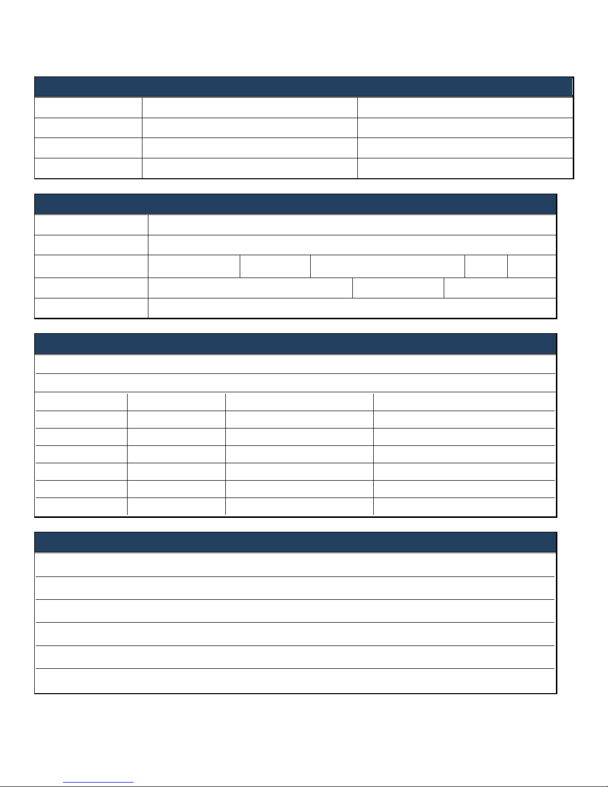
APPENDIX G: INSTALLATION ADVICE
TO
FROM
Name
Cooltrax Solution Support Team
Phone number
+61 3 9686 6011
Facsimile
+61 3 9686 9022
Email address
ASSET DETAILS
Company name
Fleet number/VIN
Reefer make
Carrier
Reefer model
Zones
Controller type
❑ Summit (Standard) ❑ Advance ❑ APX
Firmware revision
J1 connector
❑ Not present ❑ 2-way connector ❑ 10-way connector
COOLTRAX HARDWARE
❑ Wireless Gateway (UMD)
Serial number:
❑ Remote Control Maintenance Box
Serial number:
WIRELESS TAGS:
Serial Number
Type
Name or Location
❑ Wireless Tag 1
❑ Door ❑ Temperature ❑ Fuel
❑ Wireless Tag 2
❑ Door ❑ Temperature ❑ Fuel
❑ Wireless Tag 3
❑ Door ❑ Temperature ❑ Fuel
❑ Wireless Tag 4
❑ Door ❑ Temperature ❑ Fuel
❑ Wireless Tag 5
❑ Door ❑ Temperature ❑ Fuel
❑ Wireless Tag 6
❑ Door ❑ Temperature ❑ Fuel
COMMENTS
Page 39
UMD V3 Installation Manual - Remote Control 13 November 2018
Page 39 of 39
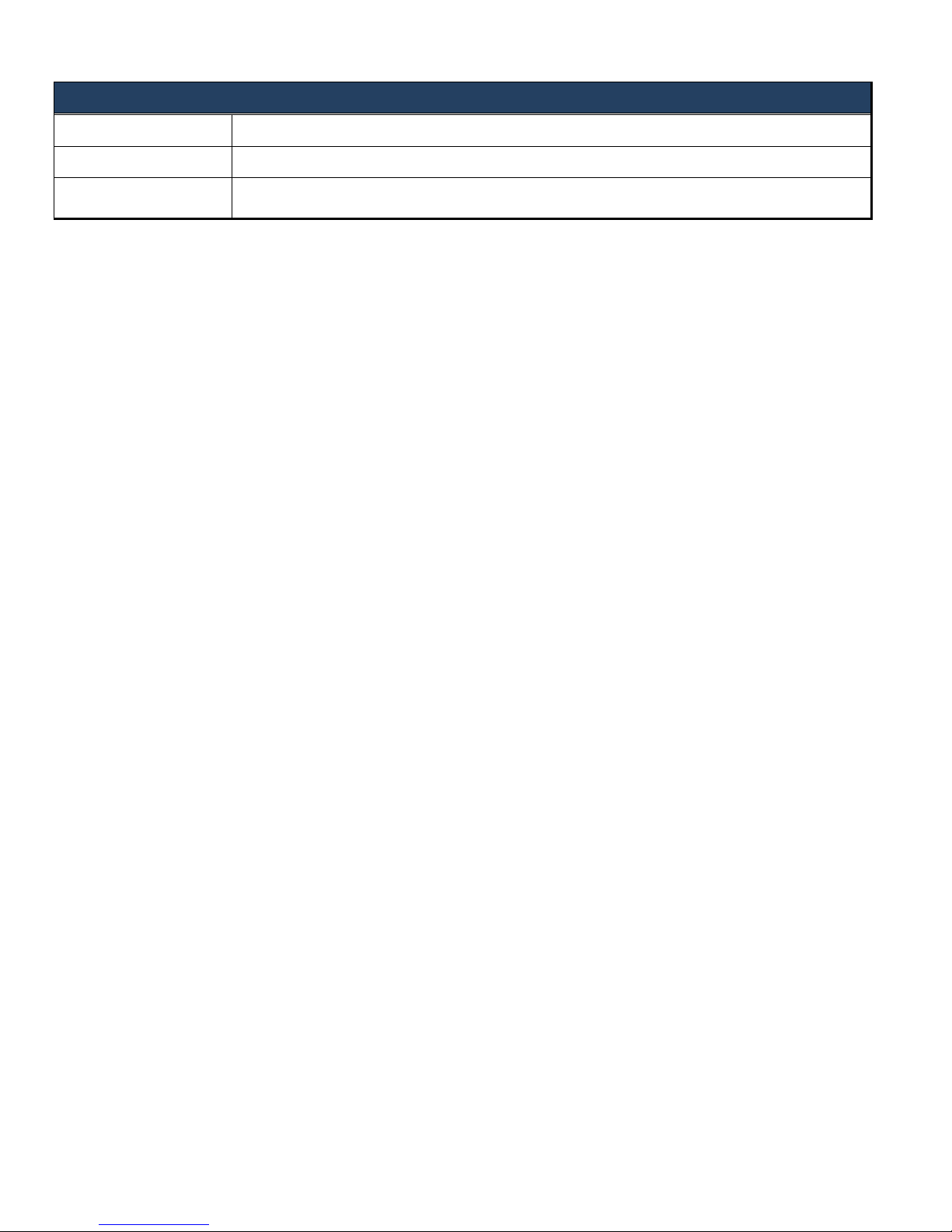
TECHNICIAN DETAILS
Your name
Company name
Signature
x
 Loading...