

CoolSpace GLACIER CS5-18-VD, GLACIER CS5-18-VD-TB2, AVALANCHE CS6-36-1D, AVALANCHE CS6-36-VD, BLIZZARD CS6-50-VD Operation And Maintenance Manual

OPERATION AND MAINTENANCE MANUAL
BLIZZARD
AVALANCHE
GLACIER
120V/60HZ
CS518VD
CS518VDTB2
CS6361D
CS636VD
CS650VD

CONTENTS
1.0 INTRODUCTION .................................................................................................................................................1
2.0 UNPACKING YOUR COOL-SPACE UNIT ..........................................................................................................1
3.0 SET-UP OF THE COOL-SPACE UNIT ................................................................................................................1
3.1 Connecting the water supply ................................................................................................................................ 1
3.2 Connecting the electrical supply ......................................................................................................................... 2
4.0 OPERATING PROCEDURES ...............................................................................................................................3
4.1 Filling the unit with water ....................................................................................................................................... 3
4.2 Starting the Fan..........................................................................................................................................................3
4.3 Starting the Pump and Adjusting the Water Flow ......................................................................................... 3
4.4 Intuitive Control Panel™ Operation ..................................................................................................................... 4
5.0 MAINTENANCE AND STORAGE.......................................................................................................................5
5.1 Removing the cooling media to access the inside of the unit ................................................................... 5
5.2 Daily maintenance .................................................................................................................................................... 5
5.3 Periodic maintenance .............................................................................................................................................. 5
5.4 Storage .......................................................................................................................................................................... 5
6.0 TROUBLESHOOTING/REPAIR ..........................................................................................................................6
6.1 Troubleshooting ......................................................................................................................................................... 6
6.2 Troubleshooting Guides ......................................................................................................................................... 7
6.3 Fan Repair Procedures ............................................................................................................................................. 9
6.4 Pump Repair Procedures ......................................................................................................................................10
6.5 Technical support ....................................................................................................................................................10
7.0 WARRANTY ........................................................................................................................................................ 11
7.1 Warranty Form .......................................................................................................................................................... 11
7.2 Warranty Parts .......................................................................................................................................................... 11
7.3 Optional Accessories and Replacement Parts ................................................................................................ 11
Due to continuous product innovations, we reserve the right to change product specication without due notice.
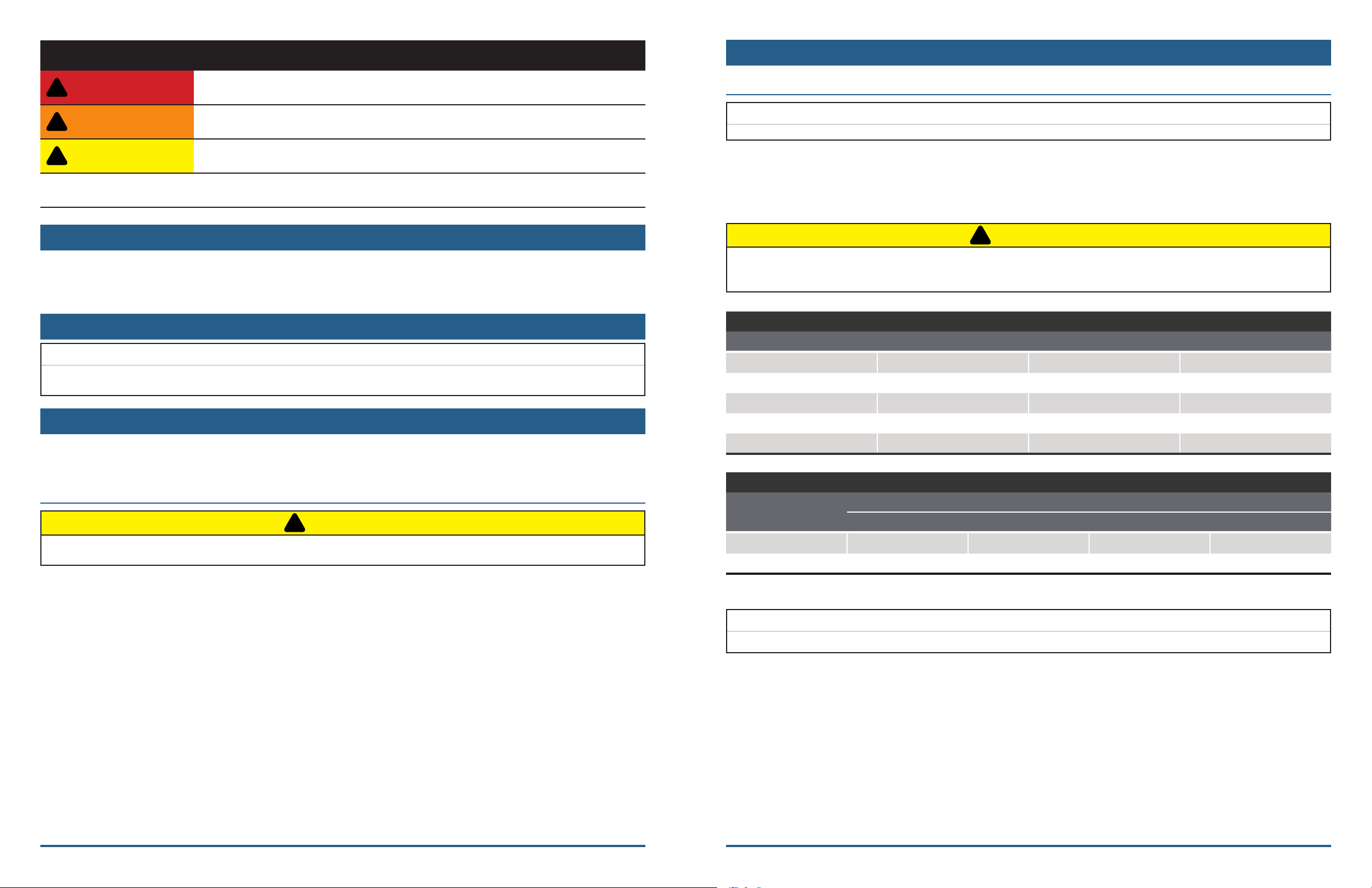
SIGNAL WORD DEFINITIONS
!
!
!
!
!
3.0 SETUP
DANGER
WARNING
CAUTION
IMPORTANT
DANGER indicates an imminently hazardous situation which, if not avoided, WILL
result in death or serious injury.
WARNING indicates a potentially hazardous situation which, if not avoided, COULD
result in death or serious injury.
CAUTION indicates a potentially hazardous situation which, if not avoided, MAY result
in minor or moderate injury.
IMPORTANT indicates a potentially hazardous situation which, if not avoided, MAY
result in property damage.
1.0 INTRODUCTION
COOL-SPACE is a patented and registered Trademark of Hale Industries, Inc. and manufactured in Indiana.
The COOL-SPACE unit is a compact, self-contained, high-eciency portable evaporative cooler.
2.0 UNPACKING YOUR COOLSPACE UNIT
IMPORTANT
Carefully examine the carton for damage before opening. If the carton is damaged notify the shipping company
immediately.
3.2 CONNECTING THE ELECTRICAL SUPPLY
IMPORTANT
The COOL-SPACE unit should be plugged into a fused or circuit breaker protected 15 amp, 120 volt, and 60 Hz circuit.
All models utilize standard 120-volt power supply. The unit should be plugged into a fused or circuit breaker protected
15 amp, 120 volt, 60 Hz circuit.
Table 1 shows the amperage requirements for the specic models. If an extension cord is required, refer to Table 2 for
the proper 3-conductor heavy-duty cord required.
CAUTION
Do not exceed the amperage ratings of the extension cord. Undersized extension cords result in excessive drops
in voltage, which cause the electric motors to generate excessive heat. This condition results in inecient motor
operation and premature motor failure, WHICH WILL VOID THE WARRANTY.
AMPERAGE REQUIREMENTS
MODEL NUMBER VOLTS ± 10% FREQUENCY (Hz) RUNNING AMPS
CS5-18 -VD 120 60 4
CS5-18-VD-TB2 120 60 4
CS6-36-1D 120 60 7.6
3.0 SETUP OF THE COOLSPACE UNIT
The COOL-SPACE unit is factory tested and ready to use. The unit should be placed on a level surface, and the casters
locked to prevent inadvertent movement. Follow instructions below to connect water and electrical supply.
3.1 CONNECTING THE WATER SUPPLY
CAUTION
Do not connect the COOL-SPACE unit to any water source where water pressure exceeds 120 psi. This will cause
permanent damage to the unit.
The COOL-SPACE unit comes equipped with a female garden hose water source connection. Attach the unit to a
standard garden hose outlet for a water source. It is not recommended that the unit be attached to any water source
with operating pressures above 120 psi. Use a standard garden hose (not provided) to connect the tank to the cooler.
CS6-36-VD 120 60 7.6
CS6-50-VD 120 60 9.3
Table 1: Electrical Requirements
3-CONDUCTOR HEAVY- DUTY EXTENSION CORD REQUIREMENTS
CORD SIZE
LENGTH (Ft)
16 GA 14 G A 12 G A 10 GA
0-50 13 A 18 A 25 A 30 A
50-100 10 A 13 A 18 A 25 A
Table 2: Cord Size Requirements
IMPORTANT
BLIZZARD-50 (SCS6-50-VD) models can not be connected to a GFCI outlet.
Page 2Page 1
 Loading...