

Page 1

CoolSky Ltd
42 Milecross Road, Newtownards BT23 4SR
Tel: +44 (0)28 9182 9470
Email: [email protected]
Company Registration No. NI072166
VAT No. GB 108838970
Copyright © 2012 CoolSky
Page 2

Apricus Installation Manual
2
TABLE OF CONTENTS
Solar Thermal Introduction 3
Technical Specification of The Apricus Collector Range 6
Solar Pumping Station 9
Pump Sizing 10
Solar Expansion Vessels 11
Sizing and Designing your Solar System 18
System Sizing 19
Sizing the Solar Cylinder 21
Pipe Type and Size 21
Stagnation & Overheating 22
Connection of Multiple Collectors 25
Balancing Flow through Collectors 25
Wind & Structural Loading 26
Back-Up Heating Source 29
Anti-Scald / Tempering Valves 29
Closed Loop Max Incoming Pressure 29
Maximum Allowable Pressure 29
Electrical Supply 30
Labelling 30
Building Considerations 31
Health & Safety Considerations 32
Installation Guidelines 34
Manifold and Bottom Support Track Assembly 35
Other System Components 37
Collector Installation 38
Connection to Plumbing 44
Insulation 44
Installation of the Tubes 46
Commissioning The System 50
Post Installation 52
Clean Up 52
Maintenance & Repair 53
Maintenance Schedule 55
Troubleshooting Guide : 56
Home-Owner Maintenance 60
Glossary of Terms 63
Important Information 64
Page 3

Solar Thermal Introduction
Introduction
CoolSky Ltd. are distributors in the U.K. and
Ireland for the Apricus range of Evacuated
Tube Solar Thermal Collectors. Since their
formation in 2002, Apricus have quickly
established themselves as a global company
with offices in USA, France and Australia with
sales in over 30 countries worldwide.
Apricus have a modern manufacturing facility
that includes a 6,500 m2 factory floor,
administration offices and an R&D Centre.
Apricus Collectors conform to the European
Standard EN12975 and carry the European
SolarKeymark Certification (
Licence No. 011-
7S161R
) as a mark of their quality, reliability
and performance.
SolarKeymark is considered to be equivalent
to MCS Product Certification thereby
qualifying the products for financial
assistance under various funded schemes
where available.
All Apricus collectors, components and
packaging have been carefully designed so
that they can be efficiently recycled at endof-life.
Solar Energy
Solar Energy is the planet’s most abundant
source of energy with the added benefit that
it is both clean and free.
(Source : EU Commission Joint Research Centre)
Whilst the UK and Ireland are considered to
have mild and temperate climates there are
parts of the UK that can receive annual
radiation levels equivalent to 65% of the
radiation that is received in places like
Madrid, Spain, making both the UK and
Ireland suitable locations for Evacuated Tube
Solar Thermal Collectors.
The Apricus Evacuated Tube Solar Collector
provides an efficient solution for the capture
of Solar Radiation and is ideal for use in UK
and Irish climatic conditions. Although the
peak solar radiation period in the UK and
Ireland is in the months from May through
to August, the Apricus Evacuated Tube Solar
Collectors are highly efficient and able to
harness the energy of the sun throughout
the year and to also provide a useful
contribution to heating during the off-peak
months.
Page 4
Apricus Installation Manual
4
Evacuated Tube Solar Thermal Collectors are
able to capture the available Solar Energy
and then transfer it as Thermal Energy to the
water heating system, thereby raising the
temperature in the hot water storage
cylinder, and offsetting the reliance to on
alternative fuels (such as coal, gas, oil or
electric) to provide hot water. Up to 70% of
the domestic hot water requirements can be
met by the Apricus Solar Collectors.
Since solar radiation levels depend upon
both the season and the daily weather
conditions it is always necessary to
incorporate a back-up water heater (typically
standard fossil fuel boilers or electric
immersion heaters) to ensure there is a
sufficient supply of hot water all year round.
Key Components of the Solar
Thermal System
Solar Energy is collected when the sunlight
strikes the black selective absorber contained
inside the evacuated tubes of the Solar
Collector.
Each tube contains a copper heat-pipe that
is in contact with the absorber. The heatpipe contains a small quantity of water
under a vacuum environment that allows the
water to start boiling at temperatures as low
as 30°C. The water vapour generated when
boiling rapidly rises to the top of the heat
pipe where it condenses and transfers its
thermal energy to the condenser and into
the copper header pipe within the manifold.
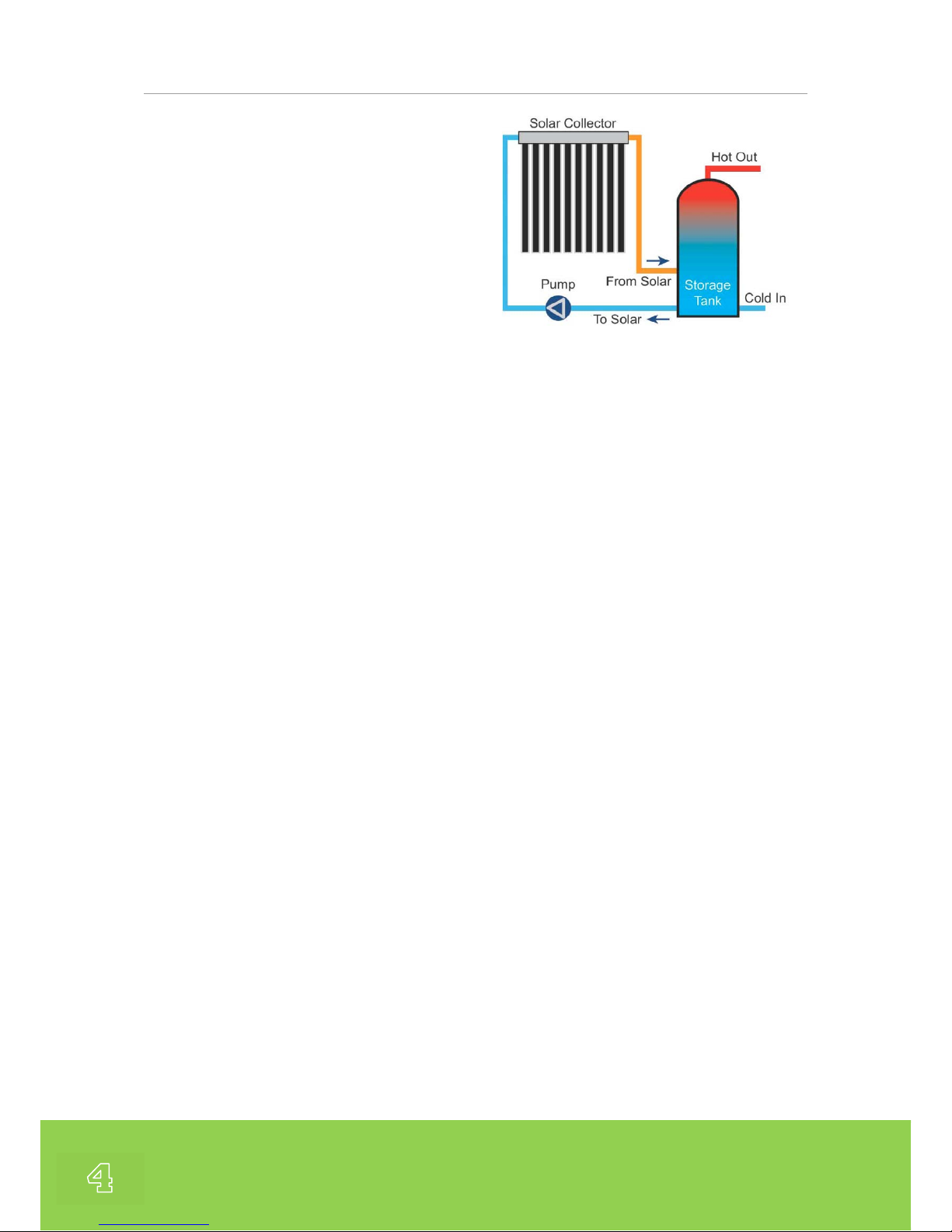
Fig. 2 Schematic showing the basic layout of a simple solar thermal
system.
The condensed fluid then flows back down
the heat pipe and is re-heated, thereby
restarting the thermal cycle again.
A circulating pump moves the heat transfer
fluid (a propylene-glycol anti-freeze mixture)
through the copper header pipe within the
manifold and back to the storage cylinder. A
solar heat exchanger coil within the storage
cylinder transfers the thermal energy from
the heat transfer fluid into the water within
the storage cylinder. The cooled fluid then
returns to the collector manifold to be reheated.
The operation of the solar loop is controlled
with a temperature differential electronic
controller. This ensures that solar fluid is
only circulated in the solar loop when there
is useful energy to transfer from the
collector into the storage cylinder.
Back-up heating using a conventional fossil
fuel boiler or electrical immersion should
also be provided for periods when solar
radiation is unable to meet the total hot
water demand.
Page 5

5
Apricus Collectors
The Apricus Collectors are available in 3
Standard Models as follows :
APSE-10 10 Tubes
APSE-20 20 Tubes
APSE-30 30 Tubes
All the Apricus Collectors are certified to the
European SolarKeymark Scheme thereby
ensuring the installer and end-user of the
highest standards and quality in materials
and manufacturing, which also qualifies the
collectors for government funded schemes
requiring MCS Certification.
The Apricus Solar Tube consists of a circular
inner absorber tube that is coated with a
selective absorber layer of Al/N on Al. This
selective absorber provides each tube with a
highly selective radiation absorbing surface,
with typical absorption efficiencies of >92%.
The absorber tube is encased within a strong
borosilicate glass enclosure that is then
placed under ultra-high vacuum conditions
to ensure the ultimate performance in terms
of thermal insulation.
A getter coating at the bottom of the tube is
used to maintain the ultra-high vacuum level
within the tube throughout its operational
lifetime and to ensure maximum collector
efficiency is achieved.
Apricus tubes have a round absorber surface
within the tube, and hence, irradiation from
the sun always strikes the absorber surface
in a perpendicular direction. This ensures
optimum collector performance whatever the
time of day, morning, mid-day or afternoon.
This is reflected in the excellent IAM
(Incident Angle Modifier) figures for the
Apricus Collectors which makes them the
ideal choice of collector for the typical UK
and Irish weather conditions where peak
solar radiation is not guaranteed to be at
mid-day.
Page 6

Apricus Installation Manual
6
Technical Specification of The
Apricus Collector Range
Model : APRICUS APSE-10
Aperture Area : 0.94 m
2
Gross Area : 1.56 m
2
Weight (Dry) : 35kg
Fluid Capacity : 0.2litres
Max Pressure : 8 bar
Stagnation Temp: 219°C
Absorption : 92%
Emission : 8%
Width x Length : 796 x 2005 mm
Height : 156 mm
Performance Figures :
η
0
62.6 %
a
1
1.595
a
2
0.013
Model : APRICUS APSE-20
Aperture Area : 1.88 m
2
Gross Area : 2.96 m
2
Weight (Dry) : 64 kg
Fluid Capacity : 0.52 litres
Max Pressure : 8 bar
Stagnation Temp : 219°C
Absorption : 92%
Emission : 8%
Width x Length : 1496 x 2005 mm
Height : 156 mm
Performance Figures :
η
0
62.6 %
a
1
1.595
a
2
0.013
Model : APRICUS APSE-30
Aperture Area : 2.82 m
2
Gross Area : 4.35 m
2
Weight (Dry) : 95 kg
Fluid Capacity : 0.71 litres
Max Pressure : 8 bar
Stagnation Temp : 219°C
Absorption : 92%
Emission : 8%
Width x Length : 2196 x 2005 mm
Height : 156 mm
Performance Figures :
η
0
68.7 %
a
1
1.505
a
2
0.011
Key Features
Manifold :
Material : Anodised Aluminium
Insulation :
Material : 50mm Glass Wool
Conductivity : 0.043 W/mK
Tubes :
Glass : 1.8mm Thick Borosilicate
Absorber : Al-N on Al
Rubber Components :
Material : HTV (UV Stable) Silicone
Max Temp. : 300 °C
Page 7
7
Storage Cylinders
Both copper and stainless steel storage
cylinders are available from CoolSky. These
cylinders are specially designed and
optimised for Solar Systems, comply with UK
regulations, and are fully compatible with the
Apricus Solar Collectors. Options are
available for both vented and unvented
systems.
As an added service we are also able to
provide cylinders that are designed and
manufactured to bespoke requirements.
Vented Solar Cylinders
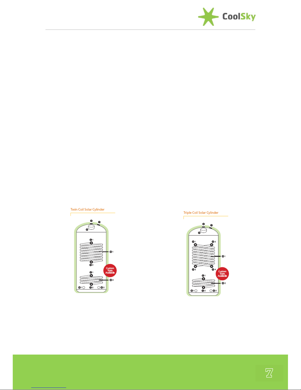
The Standard Easy-Fit Vented Copper
Cylinders are available in either twin coil or
triple coil configurations and are specifically
designed to work in conjunction with the
domestic heating system.
One or two coils are designed to transfer
heat from an independent heating source,
(eg. transferring heat from a central heating
boiler or solid fuel boiler to the water in the
solar cylinder) and the solar coil, which is
manufactured from high efficiency finned
tubes with a large surface area, to transfer
heat from the solar panels into the solar hot
water cylinder with maximum efficiency.
We are also able to supply custom sizes
upon request giving you total flexibility in
the design of your complete system. In
general, solar cylinders are sized to suit the
number of occupants and the solar thermal
panel surface area.
Nominal Diameters :
400 mm – Only Twin Coil Available
450 mm – Twin or Triple Coil
500 mm – Twin or Triple Coil
600 mm – Twin or Triple Coil
Nominal Heights :
1050 mm, 1200 mm, 1300 mm
1400 mm & 1800 mm
Unvented Solar Cylinders
The Standard Easy-Fit Unvented Stainless
Steel Cylinders are available in a twin coil
Page 8
Apricus Installation Manual
8
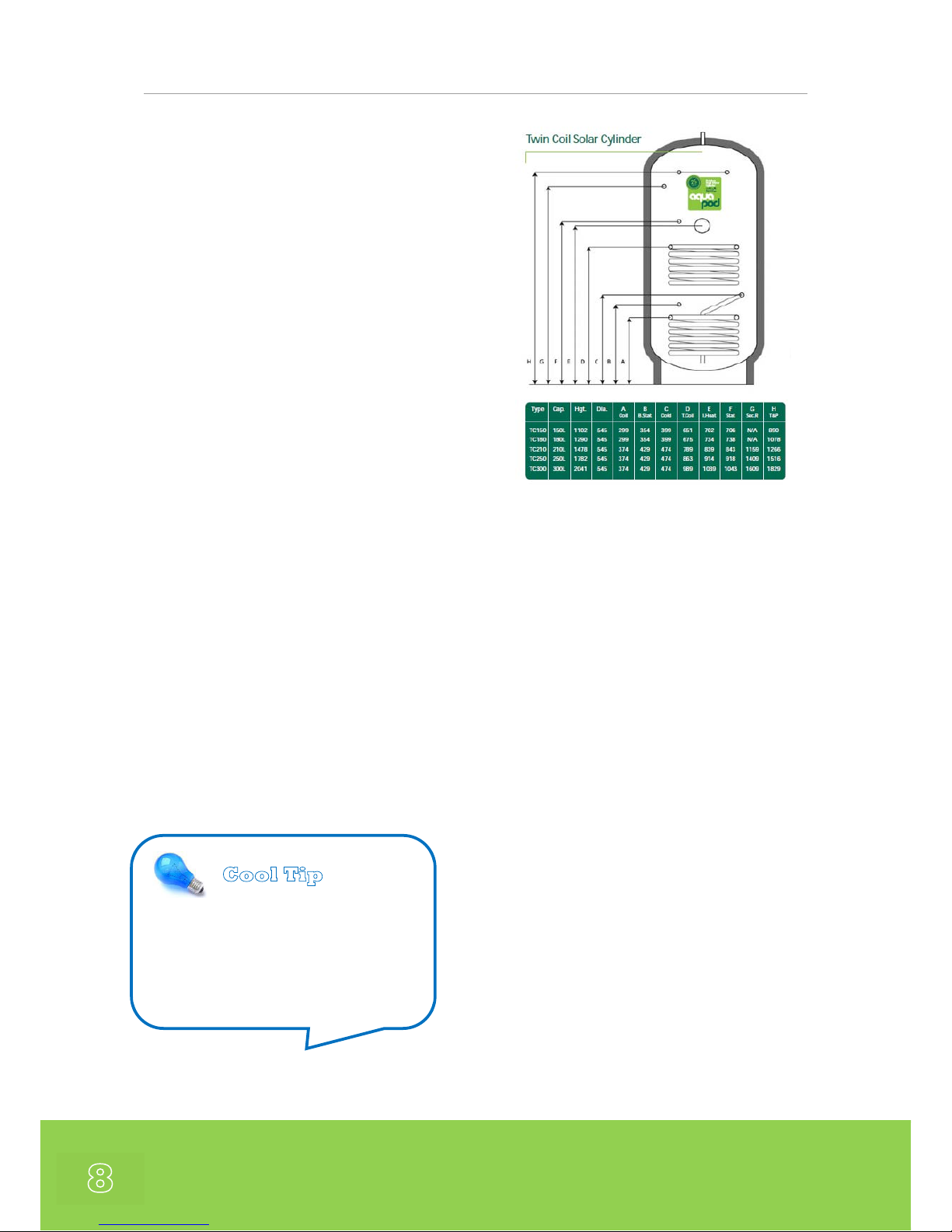
configuration and are specifically designed
to work in conjunction with the domestic
heating system.
Manufactured from Duplex Stainless Steel,
these cylinders provide fast reheat and
recovery and high value insulation. In
addition, for installers they are also light and
easy to handle
Standard Features:
Duplex Stainless Steel
25 Year Guarantee
Fast Reheat/Recovery
High Value Insulation
Nominal Diameter :
545 mm – Only Twin Coil Available
Nominal Heights :
1102 mm, 1290 mm, 1478 mm,
1782 mm, 2041 mm
Pressure & Temperature Relief
Valve (PTRV)
The storage tank must be fitted with a PTRV.
All tanks should be supplied as standard
with an approved valve.
Building Regulations
The installation of unvented hot water
cylinder for domestic applications is
regulated under Building Regulation G3 for
England and Wales, Technical Standard P3
for Scotland, Building Regulation P5 for
Northern Ireland and Technical Guidance
Document L for the Republic of Ireland. All
local, relevant and up-to-date regulations
must be adhered to by the installer. An
example schematic safety control layout for
a solar installation to comply with Building
Regulation G3 (England and Wales) is given
in the CIBSE Solar Heating Design and
Installation Guide.
Cool Tip
Rule of Thumb for sizing storage
cylinder in domestic installations:
100 litres per m
2
Aperture Area of Collector
Page 9
9
Solar Pumping Station
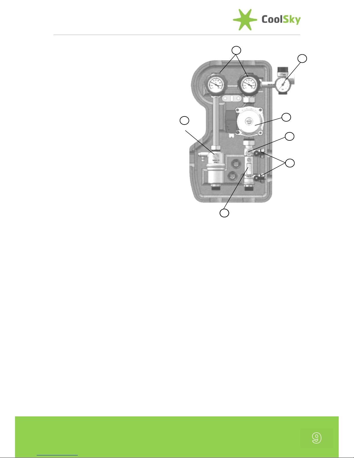
A Pumping Station is required in the Solar
Loop for the circulation of propylene glycol
heat transfer fluid around the solar loop.
The Pumping Stations are provided with the
following key features :
1. Flowmeter, flow rate regulation and
graduated scale regulation gauge 2-12
litre/min.
2. Isolation valves for filling/flushing of the
unit. Connections ¾"M with safety chain
and tap.
3. Circulating Pump - WILO solar STAR
ST15-6ECO, connections 1"BSP - 130mm
class. TF110, VDE, CE.
4. Return side isolation valve DN20, with
integrated bracket. Connection ¾"M
always open on one side.
5. Integrated high temperature check
valves. Closure at 90° and opening at
45°. Check valve opening 2kPa (200mm
c.a.)
6. Pressure gauge with integrated safety
relief valve (typ. 6Bar) with discharge
connection point for isolation valve and
expansion vessel.
7. Air stop device with manual integrated
vent.
Model Variations :
The CoolSky range of Pumping Stations are
available with either ¾” Flat Face Male
Gasket Fittings or 22mm Female
Compression Fittings.
A High Head (8m) Pump Version is also
available for larger installations.
2
1
3
4
5
6
7
Page 10
Apricus Installation Manual
10
Pump Sizing
Sizing of the Solar Pump
The standard CoolSky Twin Line Pumping
station is supplied with a 3-Speed WILO ST
15/6 Eco Pump (6m head) as standard. This
is suitable for most domestic installations
with the pump speed selected to suit the
pressure drop of the piping. Speed 1 is
generally suitable for a short pipe run, such
as on a single-storey house. Speed 3 can
normally service a 3-storey, 90 collector
pressurized system.
If the pipe run is very long or there are more
than 90 tubes in the collector array, a larger
pump may be needed. For these installations
CoolSky supply a Twin Line Pumping station
with a 3-Speed WILO ST 15/8 High Head
Pump (8m head).
If multiple banks of collectors are installed in
parallel, the head loss should be calculated
based on the longest pipe run through a
single bank of collectors and, then, the
pump can be sized to meet the total flow
rate requirements.
Please Note that Drain-back Systems will
typically require a larger rated pump.
Flow Meter
The CoolSky Pumping Staions include a flow
meter as standard to ensure that flow rates
are at suitable levels and can be monitored.
The flow meter includes a restrictor valve
allowing the flow to be adjusted accordingly.
Flow Rate
A suitable flow rate range for each 30 tube
collector is in the range of 1.5 to 3.0 litres
per minute.
Cool Tip
Set the Flow Rate through the
collector array to :
0.1 litre / minute / tube
That is :
1 litre / minute for 10-tubes
2 litres / minute for 20-tubes
3 litres / minute for 30-tubes
Page 11

11
Solar Expansion Vessels
CoolSky offer a range of different sizes of
Zilmet Solar Expansion vessels. These should
be sized according to match the
requirements of the system to which they
are connected.
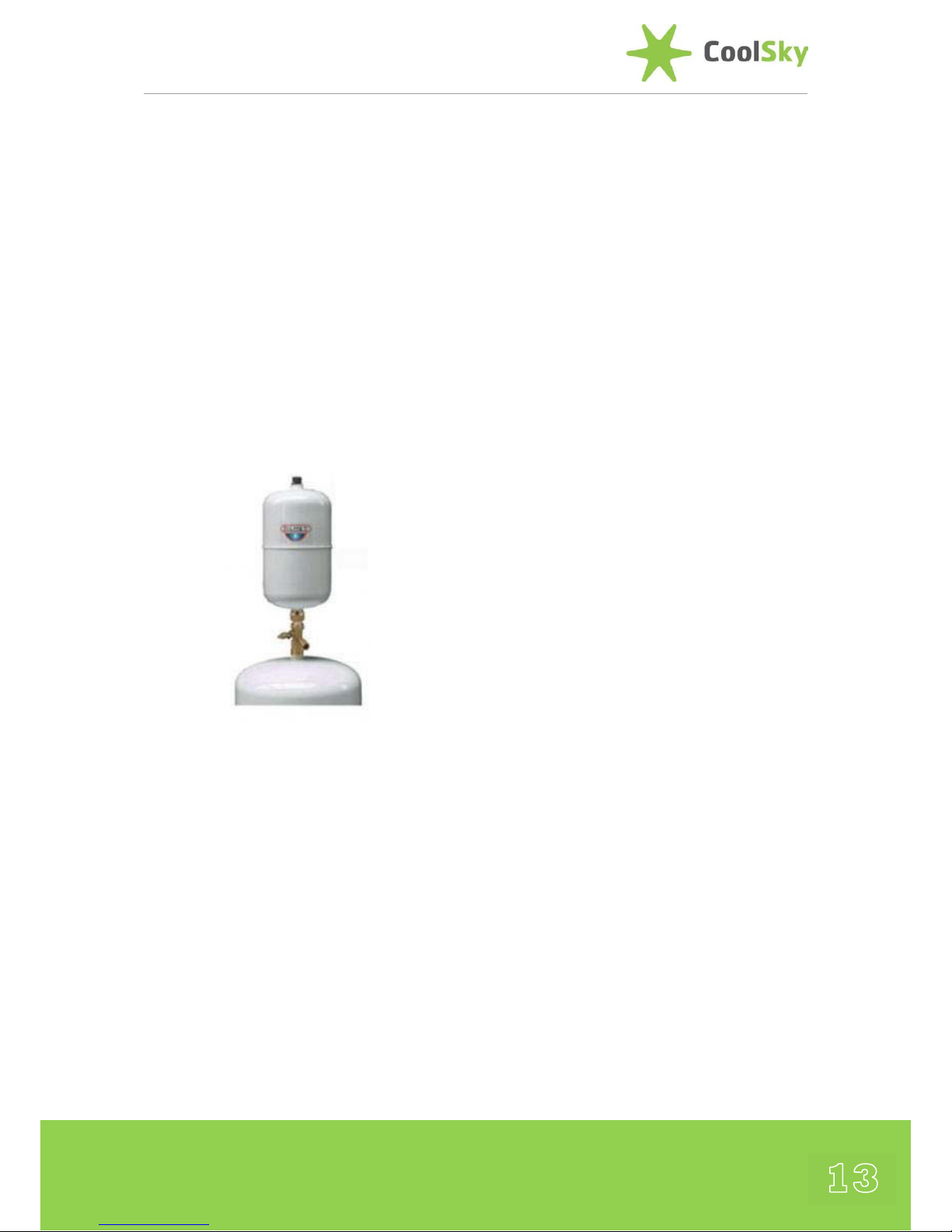
(note : solar expansion vessels should be installed with
the hydraulic connection to the top as this will reduce
heat transfer into the vessel, as shown above)
The Solar Expansion Vessels include 12, 18
and 24 litre versions which have been
specially designed for solar. Other sizes are
available upon request.
The Membrane
Inside the expansion vessel there is a special
Zilan E solar membrane structured as a bag
membrane that separates the gas from the
solar liquid. The development of the
membrane is a result from long term Zilmet
field experience in the installation of vessels
in thermal solar systems.
The membrane is stable with the Pre-Mixed
Propylene-Glycol within the solar loop up to
50% mixtures and has a max. working
temperature of 110° C. The vessel can
accommodate short peaks of 130°C glycol
temperature.
The Zilan E solar membrane is also less likely
to trap air and consequently, there is a lower
likelihood of corrosion damage to the steel
vessel.
Expansion Vessels are manufactured in
accordance with the PED 97/23/CE and
EN13831 directives, which mean that they
are fit for use in closed solar energy heating
systems according to DIN 4757 and
EN12977.
Expansion Vessel Technical
Specification
Max. Operating Pressure: 6bar
Membrane Temperature: 10° - +100°C
System Temperature: -10° - +100°C
Factory pre-charge: 2.5 bar ±20%
Nominal volume: 12, 18 & 24 L
Colour: White
Cool Tip
The Cold-Fill Pressure of the Solar
System should be :
1.3 + (0.1 x Static Height)
Where the Static Height is in
Meters.
Expansion Vessel Pressure should
be re-set to 0.3 Bar less than the
Cold Fill Pressure.
Page 12

Apricus Installation Manual
12
Expansion Vessel Connection Kit
CoolSky also provide an expansion vessel
connection kit to connect the expansion
vessel to the safety group on the pumping
station. Each kit includes a wall fixing
bracket and a self-closing system isolation
valve (so that the vessel can be removed for
maintenance without draining the fluid from
the system and to facilitate periodic gas
charge checks).
A pre-formed stainless steel flexible hose is
also provided to connect the vessel to the
system at the connection point provided on
the CoolSky Solar Pumping Station.
It is recommended that the Pumping Station
and Expansion Vessel are located as far
hydraulically away in the Solar Loop from the
Solar Collector as is practically possible. This
is to protect the Pumping Station and
Expansion Vessel from the very high
temperatures (i.e. >200 °C) that can be
generated by a Vacuum Tube Collector
under stagnation conditions.
Mounting the Expansion Vessel
Always mount solar vessels in a vertical
position and recognised best practice is to
connect to the provided connection port on
the pump station. Where possible, mount
below the pump station to negate heat
transfer.
Avoid mounting in close proximity to the
solar collector where temperatures can
exceed 130°C. In cases where this cannot be
avoided, it is highly recommended that the
expansion vessel be installed in conjunction
with a heat protecting ‘intermediate’ vessel.
Intermediate Vessels
Intermediate vessels are also available and
are recommended on solar thermal systems
where it is likely that temperatures within the
system will exceed the maximum allowable
working temperature of the expansion vessel
Cool Tip
Always check the internal pressure
of the Expansion Vessel before
fitting and reset to 0.3 bar lower
than the intended cold-fill pressure
of the Solar Loop.
Page 13
13
or where the expansion vessel is in close
proximity to the solar collector.
It is particularly important that an
intermediate vessel is installed on systems
where the volume of the collectors exceeds
the volume within the flow and return
pipework. This is because during stagnation
periods, the very hot solar fluid in the
collectors can reach vaporisation point. If this
occurs, the very hot solar fluid is forced out
by the vapour, into the expansion vessel.
Intermediate vessels have inlet/outlet
connections and are installed just before the
main expansion vessel (as shown above). The
heat sink that the intermediate vessel
provides, reduces the working temperature
at the diaphragm, and hence considerably
extends the working life of the expansion
vessel.
Page 14

Apricus Installation Manual
14
Sizing the Expansion Vessel
To size an Expansion Vessel for a Solar
Application the following equation can be
used :
Where
V
EV
= Nominal Expansion Vessel Size [L]
V
SYS
= Total Volume of System [L]
VSS = Volume of Safety Water Seal [L]
= 0.005 x V
SYS
or
= 3 Litres
(whichever of above is greater)
β = Solar Fluid Expansion Coefficient
= 0.13 for CoolSky Fluid
V
COL
= Volume of Collector
= 0.3 Litres for AP-10
= 0.5 Litres for AP-20
= 0.7 Litres for AP-30
n = Number of Collectors
PSV = Pressure Relief Valve Setting
= 6 Bar as CoolSky Standard
P
MAX
= Allowable Max Pressure in Bar
= P
SV
– (0.1 x PSV)
= 5.4 Bar (for a 6 Bar PRV)
HST = Static Height of System
= Height of Collector from Pump
PEV = Gas Pressure of Expansion Vessel
= 1 + (0.1 x H
ST
)
CoolSky recommend that an additional
safety factor of 1.5 is applied to the V
EV
value to account for the possibility of steam
in the solar loop.
Examples of typical domestic Expansion Tank
Capacities are given in the table below.
Apricus AP-30 Collector
Aperture
Area
[m
2
]
System
Volume
[Litres]
Static
Head
[m]
Expansion
Tank
[Litres]
3 6.9 5 18
10 18
6 7.6 5 18
10 18
9 8.3 5 18
10 18
12 9.0 5 18
10 24
The above are based upon a system using
the Apricus AP-30 Collector with 20 meters
of DN16 Flexible S/S Pipework and a Heat
Exchanger with 2 litre capacity.
The CoolSky Technical Design Team can
provide assistance and support for the sizing
of Solar Expansion Vessels for your
installation if required.
Page 15
15
Solar Thermal Anti-Freeze
CoolSky recommend that a Solar Thermal
Anti-Freeze Fluid is ‘always’ used in Solar
Collector Installations. CoolSky supply a premixed (40% propylene glycol, 60% water)
thermal transfer fluid with additional
corrosion inhibitors for use with the Apricus
Solar Collectors. The fluid is supplied in 20
litre drums.
Only Thermal Fluids that are formulated for
use with High Performance Evacuated Tube
Solar Collectors should be used, as these
have special liquid corrosion inhibitors that
are able to vaporise and condense effectively
during normal collector operation.
The fluid is specially developed for
Evacuated Tube Solar Thermal collectors and
provides frost protection to -28°C.
Protective goggles and rubber gloves should
be used when handling the thermal fluid.
A full Material Safety Data Sheet (MSDS) is
available from CoolSky Ltd. upon request.
Disposal of the fluid should be in accordance
with local regulations.
Although some Solar Controllers are
provided with a Frost Protect Function it
must be highlighted that this only functions
when there is electrical power provided to
the controller and pumps. In the UK and
Ireland it is not unusual for extremely cold
weather conditions to be accompanied by
power outages due to falling power lines,
thereby rendering the Frost Protection
Function ineffective. Only the use of a
suitable anti-freeze fluid will protect the
solar collector from freezing in the combined
conditions of extreme cold and power
outage.
Apricus Evacuated tubes are not susceptible
to damage in cold weather, and Apricus heat
pipes are protected against damage that
could result from the freezing of the water
inside by the addition of a special frostprotection additive.
Within the manifold and pipework of the
solar loop a suitable Solar Anti-Freeze fluid
must be used. Contact CoolSky for details of
suitable Anti-Freeze Fluids.
✖ Freeze related damage is not eligible for
warranty claims.
WARNING:
Failure to implement effective (and
fail-safe) freeze protection may result
in rupture of piping and substantial
property damage.
Page 16
Apricus Installation Manual
16
Solar Heat Dissipater
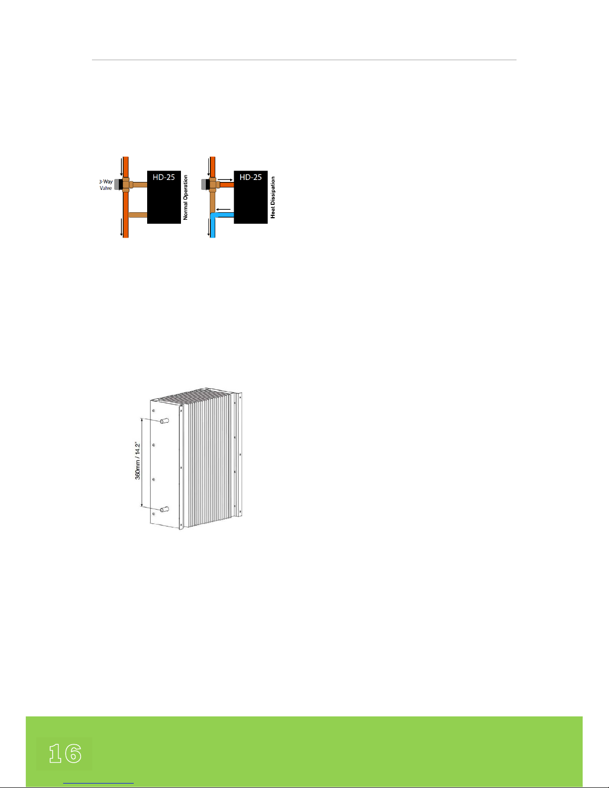
The Apricus HD-25 is an air to water radiator
designed to dissipate the energy produced
by one AP-30 collector.
Heat dissipation may be necessary when
solar thermal systems are designed for space
heating applications which may produce
more energy than is needed during warmer
seasons, or for systems where there is an
irregular or low summer demand, for
example, schools, holiday homes and sports
clubs.
The Apricus HD-25 is an ideal solution to
protect from excessive overheating and can
prevent premature ageing of the heattransfer fluids used in the solar loop.
Materials of Construction
Piping: Copper (Ag-Zn-Cu brazed)
Fins: 3A21 Grade Aluminium
Case: 3A21 Grade Aluminium
Dimensions
Height: 500mm
Depth: 172mm
Width: 375mm
Heat Transfer Area: 2.8 m
2
Gross Weight: 6.6 kg
Inlet/Outlet Pipe: Ø15 mm x 1.0mm
Heat Loss Performance
When ΔT . 40°C, heat dissipation ≥1.3kW
For optimal performance ensure good
natural air circulation.
Installation Guidelines
Max Flow Rage: 15L/min
Ideal Location: Good natural air flow
Transfer Liquid: Propylene Glycol (≤50%)
Page 17
17
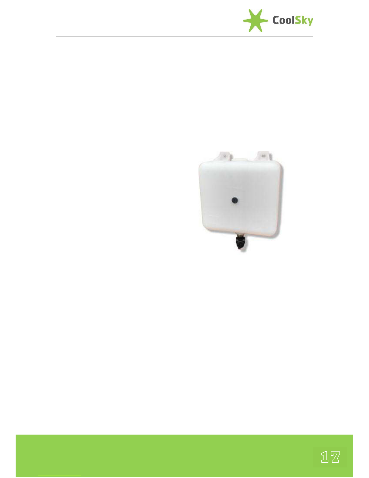
Safety Valve Discharge Container
A high temperature discharge container has
specially designed to capture any propylene
glycol fluid that is discharged from the
Pressure Relief Vessel on the Solar Pumping
Station and to allow its recovery during
regular maintenance - neatly avoiding the
issues of potential damage to those areas
surrounding the valve.
The unit is manufactured from high
temperature grade plastic material that is
suitable for solar systems and up to 160°C
short bursts of glycol/steam. The captured
fluid is visible through the opaque tank
which is supplied complete with a drain
valve.
Technical Specification
Capacity 9.6 litre
Drain valve integral
Size 300 x 270 x 130mm
Clearance required 440mm high
Construction Plastic PE
Ambient temp -5° - +50°C
Storage -10° - +60°C
Short term discharge 160°C
Page 18
Apricus Installation Manual
18
Sizing and Designing your Solar
System
When starting to design your solar system,
the first issues to consider are regarding the
installation site and the practicalities of
installing the solar collectors.
This section will provide you with detailed
guidelines about assessing the suitability of
any given site for the installation of the Solar
Collector.
Standard System Designs
CoolSky have developed a standard set of
system designs, which represent the most
commonly installed configurations in the UK
and Ireland. We recommend adhering to
these system designs. Any modifications to
the design should be checked by a qualified
engineer.
When using these designs it is important
prior to installation, to confirm that the
designs meet any local regulations.
All systems must be installed by authorised
persons. Upon completion of the
installation, the system may also need to be
checked by a plumbing inspector prior to
commissioning, depending upon local
regulations.
Free Bespoke Design Service
The CoolSky Technical Design Team can also
offer our customers a full bespoke design
service. System designs and configurations
for both small and large systems can be
tailored to our customers particular
requirements. Contact CoolSky for more
details on our Free Design Service.
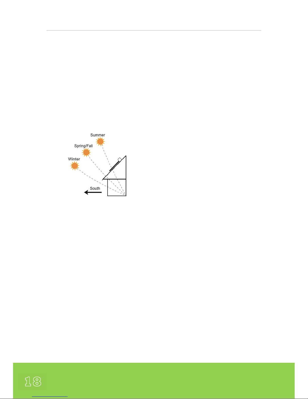
Collector Direction
Ideally the collector should face as close to
due South as possible. A deviation of up to
15
o
to the East or West is acceptable and
will have minimal effect on collector
performance.
If installed due east or west, the solar
collector output will be considerably
reduced, with predominately morning output
or afternoon output for each direction
respectively. However, a dual collector
option exists with one collector facing east
and the second collector facing west. This is
commonly referred to as an “East-West
System”.
NOTE: Installations at or near due East or
West will mitigate the passive tracking effect
of the round absorbers within the Apricus
evacuative tubes. Collectors should not be
installed facing a northerly direction.
Collector Orientation
The collector manifold is normally installed
on the flat horizontal plane with the tubes
pointing downwards from the manifold. The
collector must not be installed up-side-down
(tubes pointing upwards) or with tubes lying
Page 19

19
horizontally, as the heat pipes will not
function.
Drain Back Systems
In a drain-back configuration the collector
must be positioned with 2cm of drop per
meter.
Installation Angle
The solar collector must be installed at an
angle of between 20-80
o
from horizontal to
ensure optimal heat pipe operation. For
optimum summer performance for Domestic
Hot Water applications, as a rule of thumb
the installation angle is typically set as :
Install Angle = 0.7 x Location Latitude
In areas prone to hail, a minimum angle of
45
o
is advisable. Similarly, in areas prone to
high snow loads, 45
o
or higher is advisable
to encourage the snow to fall off the
collector surface.
Avoid Shade
Collectors should be located so that shading
does not occur between 9am - 3pm which
are the peak sun hours.
Partial shading due to small objects such as
antennas and small flues is not a problem.
If installing multiple rows of collectors
consider the shading of collectors on the
row behind (especially in the winter).
Location of Collector
The collector should be positioned as close
as possible to the storage tank to avoid long
pipe runs.
System Sizing
Domestic System Sizing
For residential domestic water heating
applications basic “rules of thumb” exist that
allow system sizes to be calculated using the
methodology outlined below.
For space heating or commercial water
heating system the sizing calculations are
more complicated. The CoolSky Technical
Design Team can assist our customers with a
free design service for these systems. Using
special state-of-the-art Solar Thermal design
packages we can assist in the design and
optimisation of all Solar Thermal systems no
matter what the size.
How much hot water is needed?
Ideally the exact daily hot water demand
should be provided through metering.
However, as this is not always available, the
daily demand can be estimated using the
following guidelines :
Cool Tip
Rule of Thumb for Optimum
Installation Angle
0.7 x Location Latitude
Page 20
Apricus Installation Manual
20
Consumption
Demand
Liters of Hot Water
at 60°C per person
LOW 15
MEDIUM 30
HIGH 60
Guidelines for Domestic Hot Water Useage
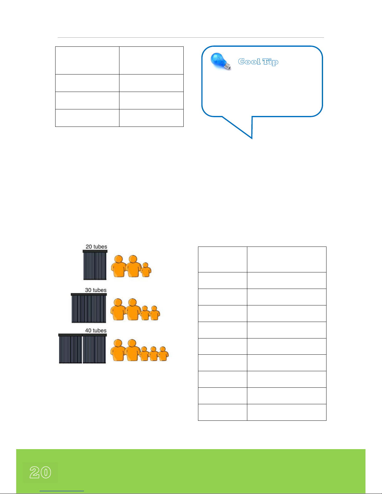
A general Rule of Thumb for UK / Ireland is
to assume a requirement of 50 litres of Hot
Water per person per day.
The graphic below shows typical sizing
guidelines for collectors when used for
Domestic Hot Water production in the UK
and Ireland.
Guidelines for Collectors Sizing to Match User
Demand for Domestic Hot Water
Commercial Collector Sizing
Sizing a commercial system usually requires
the use of professional modelling software.
CoolSky can offer a free design service to
our customers for these jobs.
The table below gives guidelines to typical
Hot Water Demands in commercial
applications.
Type of Building
Max. Liters of Hot Water at
60°C per person
Restaurant 6
Factory 15
Offices 14
Hotel 5* 136
Hotel (Avg) 114
Sports Facility 40
Hospital 128
Holiday Home 50
Camp Site 40
Typical Hot Water Demands in Commercial Type
Properties.
Cool Tip
Rule of Thumb to Estimate Hot
Water Demand at 60 ‚ C in UK and
Ireland :
50 litres per person per day
Page 21

21
Sizing the Solar Cylinder
Domestic Sizing
The storage cylinder sizes for domestic solar
thermal installations should be sized
according to the following minimum
guidelines :
20 Tubes = 200 Liter cylinder
30 Tubes = 300 Liter cylinder
40 Tubes = 400 Liter cylinder
60 Tubes = 600 Liter cylinder
The storage capacity can be a single tank or
multiple tanks plumbed in parallel.
Using a smaller capacity tank will lead to the
system reaching maximum temperature
sooner, which will often result in wasted
and/or uncollected energy.
If the installed collector area exceeds the
storage capacity of the cylinder there will be
wasted energy and excess heat in sunny
weather. Letting the collector stagnate is an
acceptable means of preventing excessive
tank temperatures during summer, but
stagnation periods should be minimised in
frequency and duration for the sake of
overall system efficiency. Otherwise, the
longevity of the evacuated tubes may be
compromised by more rapidly reducing the
vacuum level.
Commercial Cylinder Sizing
Sizing storage for commercial applications is
more complex than residential sizing and
requires a detailed evaluation of hot water
usage patterns.
Commercial applications are too varied in
demand, peak demand, required output
temp, etc. for set, rules to apply. Hot water
usage patterns and the total hot water
demand should both be considered. Use of
modeling software is strongly advised when
designing Commercial Systems and this is an
area where CoolSky can provide system
designs expertise to our customers.
Pipe Type and Size
Pipe Material
The solar collector loop can get very hot (i.e.
200°C under stagnation conditions) and
therefore the only recommended material
choices are copper (hard or soft coiled) or
corrugated flexible stainless steel pipe.
Cool Tip
Rule of Thumb to Size the
Storage Cylinder :
10 litres per Solar Tube
Page 22
Apricus Installation Manual
22
Plastic Pipe (PEX) or Galvanised Pipe should
‘NEVER’ be used in any part of the Solar
Loop within a Solar Thermal Collector
System.
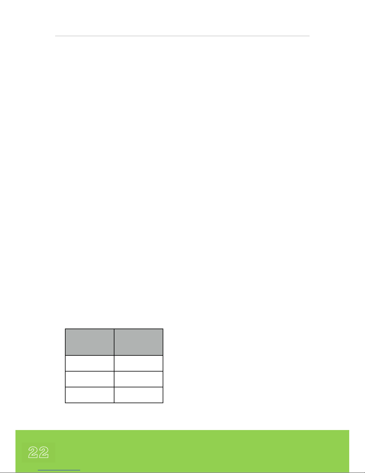
Pipe Size
When selecting the size of the pipe for the
solar loop there are two main issues to be
taken into account: flow rate and pressure
drop
These two factors are closely related; a
higher pressure drop will reduce the flow
rate.
Pressure drop is increased with a smaller
diameter pipe, as well as the presence of
bends, elbows and other components that
will restrict the flow of the water such as
corrugated stainless steel piping.
A relatively direct, unobstructed flow path is
highly desirable.
If there is the possibility that additional
collectors will be added to the system in the
future then it is recommended that a lager
pipe diameter is used to accommodate the
future system expansion / upgrade.
Number of
Tubes
Pipe Size
Cu / SS
10-40 15mm / DN16
50-90 22mm / DN20
90-240 25mm / DN25
Guidelines showing pipe sizing for typical domestic
installations
Securing Pipes
Pipes must be secured in place with suitable
brackets, straps, etc. according to plumbing
code requirements for material and pipe
diameter and to prevent vibration and
placing stress on system components.
Internal Piping
Extra care must be taken to avoid any piping
leaks inside the building. Avoid joints in
attic or overhead spaces that could cause
significant property damage if they were to
leak. The CoolSky Standard Systems have
been designed to minimize the number of
hydraulic connections and we recommend
the use of Flat Face gasket seals for the
hydraulic connections where possible.
External Piping
Long external pipe runs should be avoided
where possible. Pre-insulated pipes should
have a sheath to protect the insulation from
UV degradation.
Stagnation & Overheating
What is Stagnation?
Stagnation refers to the condition that
occurs whenever the pump stops running.
This could be due to pump failure, power
outage or most commonly, as the result of a
max tank temperature protection feature
setting on the controller.
Page 23

23
During stagnation, the collector, unable to
actively dump heat, will continue to rise in
temperature until the heat loss from the
collector and piping equals the heat being
absorbed. In strong sunlight with high
ambient temperatures, the collector can
reach peak stagnation temperatures from
160-220
°
C. Hence, components that may be
exposed to these high temperatures such as
valves, plumbing or insulation should be
suitably rated.
Pressure Loss with Height
Even though a system might be a closed
loop and pressurized, there is always some
pressure loss caused by height. This is
extremely important to understand when
deciding the system pressure. The loss of
pressure is about 0.1 bar per vertical meter.
A low system pressure at the collector can
result in bubbles (vapour) forming within the
heat transfer fluid due to a lowered fluid
boiling temperature. These bubbles can
collect in high points in the solar loop
piping, especially within the collector itself,
and cause air locks in the system that will
result in stagnation, because the pump does
not have the power to push fluid through
vapour pressure.
Size System to Avoid Overheating
The system should be sized so that
overheating of the tank is difficult to achieve
in a single day, even during hot, sunny
periods.
For properly sized open and closed loop
systems with suitable heat transfer fluid, it is
acceptable for the system design to allow
the solar collector to stagnate (i.e. stop the
pump) from time-to-time to prevent
overheating of the storage tank above the
maximum cylinder set temperature. An
expansion tank must be properly sized and
installed to accept the increase in fluid
volume due to thermal expansion and
potential steam formation, in order to
minimise or prevent release of fluid from the
pressure relief valve.
If the system is over-sized, so that stagnation
occurs often during summer months, the
system must be able to stagnate repeatedly
without damage or heat transfer fluid
degradation. Using stagnation as a daily
means of dealing with an oversized system is
NOT recommended.
✖ Gradual loss of vacuum in evacuated
tubes over time during normal use is not
eligible for warranty claims.
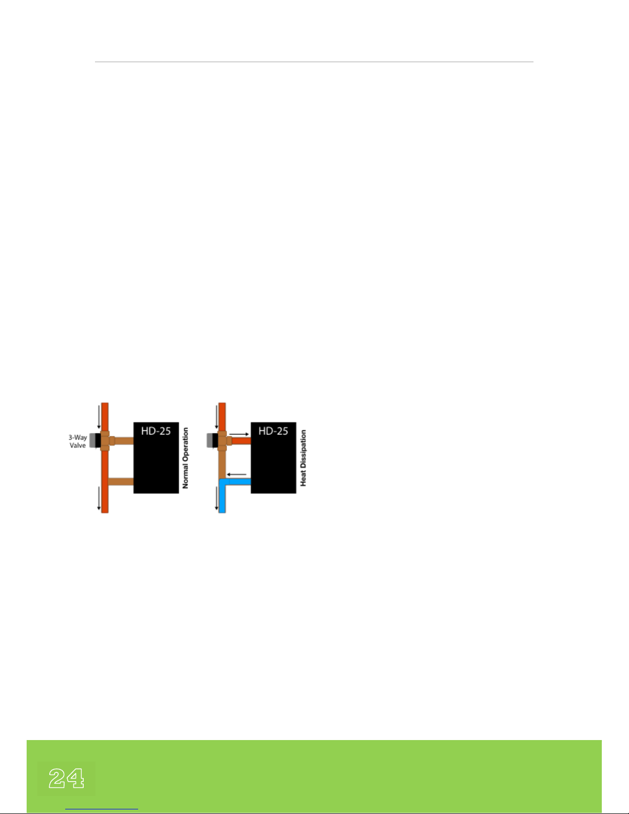
Heat Dissipation
For systems designed for space heating that
produce excessive summer heat output a
heat dissipation loop should be installed.
CoolSky offer an Apricus kit specially
designed for this purpose, the HD-25 Heat
Dissipater. This unit can be installed above
the pump station on the Flow Line from the
Page 24
Apricus Installation Manual
24
collector.
The unit is a finned fluid to air style radiator
that can be used to dissipate heat from the
system once the tank has reached the
maximum temperature. The heat transfer
fluid circulates through the copper pipe
transferring heat to a set of large aluminum
fins, which in turn dissipate heat to the
surrounding air. Each HD-25 unit can
dissipate up to 1.5kW or greater with active
air flow and is suitable to dissipate the
excess energy from one (1) Apricus 30-Tub e
Collector.
Note: The HD-25 is for external installation
only.
Alternative Thermal Dumps
During the summer, heat can also be
dumped into a hot-tub, jacuzzi, pool, towel
radiator, large storage tank or underground
thermal store.
Increased Angle Reduces Summer
Output
Apart from installing a smaller collector, a
good method of reducing summer heat
output is to angle the collector for optimal
winter absorption. This is achieved by
installing the collector at an angle 15
°
-20
°
above the latitude angle (so long as the
collector remains within the recommended
angles of 20
°
to 80°). This angle corresponds
closely to the angle of the sun in the sky
during the winter, thus maximizing winter
output. Conversely, during the summer
when the sun is high in the sky, the relative
surface area of the collector exposed to
sunlight is reduced, lowering overall heat
production by about 20-25%. This option is
ideal for installations that use solar thermal
for space heating. However, this depends
upon the overall size of the collector array
and a heat dissipation unit (or units) may still
be required for larger arrays.
Page 25
25
Connection of Multiple Collectors
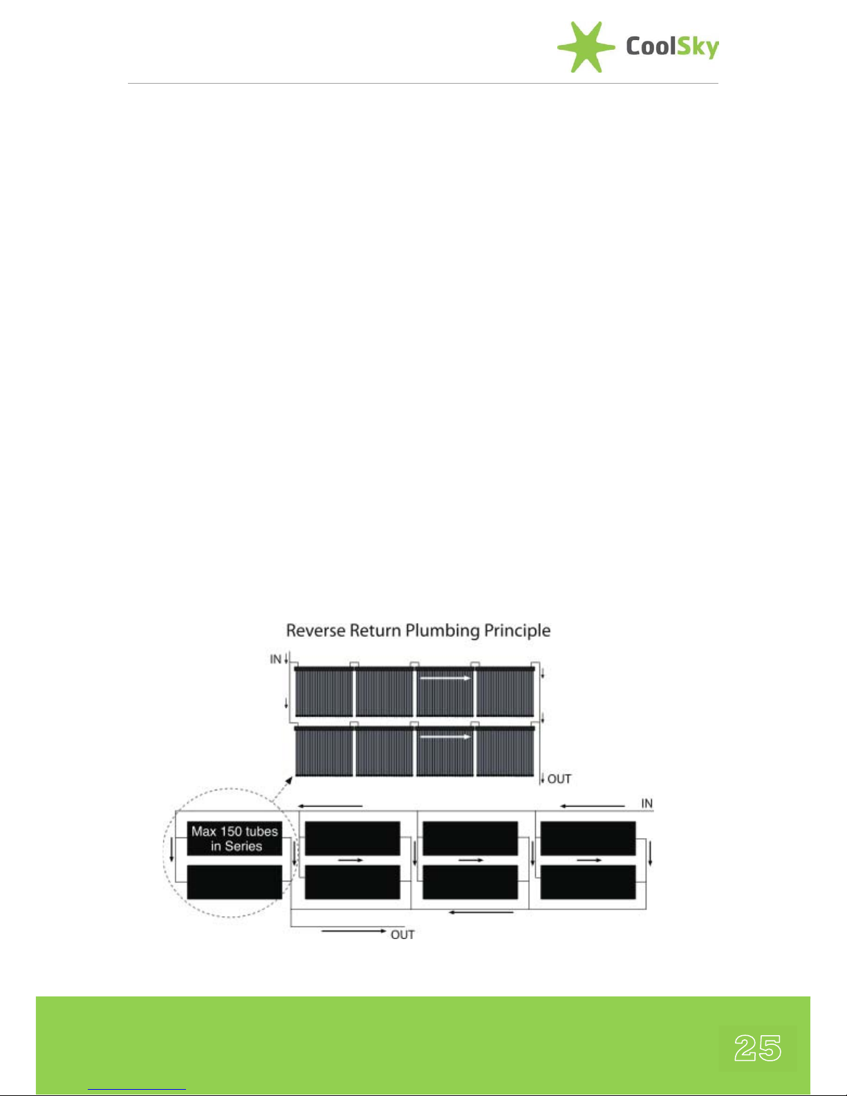
It is only recommended to connect up to
150 tubes in series (i.e. 5 x AP-30 Collectors
with a maximum flow rate of 15 l/min
through any Apricus Collector.
✖
Damage to collectors due to heat
expansion and copper header distortion is
not eligible for warranty claims.
Balancing Flow through Collectors
When connecting multiple banks of
collectors (a bank being 1-5 x 30 tube
collectors in series) in parallel, the flow rate
through each bank MUST be equal.
Otherwise, some collectors will run cold, due
to higher flow rate while others will run hot,
due to lack of flow. This is not an issue for a
single bank of up to 150 tubes connected in
series.
Reverse Return plumbing, or “first in - last
out”, is an effective piping configuration that
helps to ensure balanced flow. However,
there are affordable, high quality flow setters
or circuit setters available and they are often
a better choice, as they minimize pipe run
length, costs and heat loss. Below is a
diagram of reverse return piping.
Page 26
Apricus Installation Manual
26
Wind & Structural Loading
Components must be able to withstand
environmental forces such as wind loading,
snow loading, rain and hail. They must also
be securely and positively fastened to the
structure.
Collector wind loading must be considered
and the resulting stress on attachment
points thoroughly examined.
The standard Apricus Frame and Frame Kits
are all designed to withstand wind speeds of
up to 130 mph (208 km/h) without damage,
which corresponds to the mid-range of
Category 2 cyclones (US Saffir-Simpson
scale).
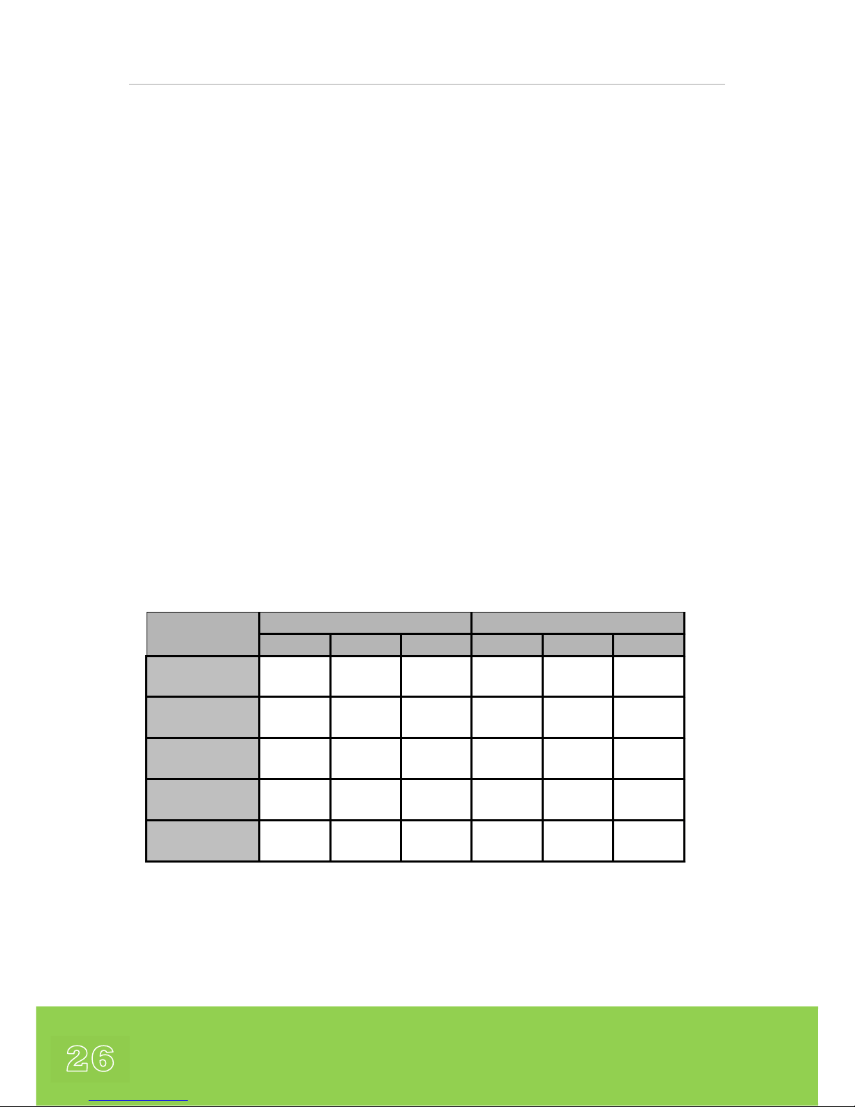
Tab l e A provides peak vertical pull forces and
horizontal (pushing) forces for an AP-30
collector. These values represent both rear
and frontal winds. The highest force of 180
kg on the middle, front foot at a 60
°
collector angle is actually from a frontal, and
not rear, wind as it is trying to tip the
collector backward.
Based on the figures provided in Table A, the
weight of individual concrete blocks or the
strength of fixation points requirements can
be determined.
NOTE :
A safety factor of at least 1.2 should be
used, or as specified by local building
regulations, whichever is higher.
30o Angle 45o Angle 60o Angle 30o Angle 45o Angle 60o Angle
Front Middle
22 8 40 59 100 180
Front Left/Right
15 13 43 32 74 100
Rear Middle
38 85 122 18 31 66
Rear Left/Right
32 78 114 17 24 58
Combined Load
156 275 488 127 327 808
Round Foot
Peak Vertical Pull Load [kg]
Peak Forward-Backw ard Load [kg]
Table A – Showing the Peak Loads on the Collector Feet when subjected to wind
speeds of 130 mph (208 km/h)
Page 27

27
If using concrete blocks under the feet,
connecting the blocks together, particularly
front and rear, is advisable as it can help
spread the load. This applies particularly to
the middle legs which are exposed to the
peak loads. Before ballasting the system with
concrete or other weights, be aware of the
total weight live and dead load capacity of
the roof structure and determine if the roof
can safely handle this attachment method.
Other mounting methods in high wind
regions may require inspection and approval
by a licensed engineer or the local building
authority.
NOTE :
It is the responsibility of the installer to
ensure that the frame mounting is of
suitable strength.
✖ Wind related frame and collector damage
is not eligible for warranty claims.
Snow Load
The UK and Ireland as a whole are not
generally considered to be areas prone to
heavy snow falls. However, in areas prone to
heavy or regular snow falls, or where the
accumulation of snow on the collector is of
concern, the solar collectors can be installed
at an angle of 50
o
or greater to promote
snow sliding off the tubes. In addition, it is
advisable to raise the front of the collector
frame 15 to 20cm off the roof surface as this
allows the collector to sit above moderate
snow falls and allow snow to blow away
from under the collector. A front track
extension available from CoolSky can be
used for this purpose.
Each tube is strong enough to withstand
>50kg loading, but roof attachment points
may need to be reinforced. Please refer to
local regulations regarding snow loading
precautions.
✖ Snow loading damage to the collector is
not eligible for warranty claims.
Hail Resistance
The UK and Ireland are not considered to be
areas subject to extreme hail conditions.
The Apricus tubes are manufactured from
robust borosilicate glass and are able to
handle significant impact stresses. Testing
and impact stress modelling shows that the
tubes are able to withstand impact from hail
up to 25 mm in diameter, and even larger
when installed at angle of 45
°
or greater.
In areas prone to hail over 20 mm in
diameter, or where hail impact is of concern,
it is recommended that the solar collector be
installed at an angle of 45
°
or greater to
provide optimum impact resistance.
Page 28

Apricus Installation Manual
28
In the unlikely case that a tube breaks, it can
easily be replaced. The solar collector can
still function properly with one or more
broken tubes, however, a reduction in heat
output will result (depending upon how
many tubes are broken). A broken tube
should be replaced by authorised persons
only.
✖ Hail related damage to the collector is not
eligible for warranty claims.
Lightning Protection
It is advisable to earth-ground the copper
circulation loop of the collector to avoid
lightning related damage, or electrical safety
issues. It may also help to prevent galvanic
corrosion of the copper pipe which can
result in blue staining of basins/baths etc.
Ultraviolet (UV) degradation
Any components installed outside must be
able to withstand UV radiation without
significant degradation. Colour fading is
common, but cracking, peeling and other
severe degradation should not occur during
the design-life of any component in the
system.
Coastal Regions
Apricus collectors are manufactured using
439, 301 and 304 grade stainless steels for
the solar collector frames, clips and
fasteners. These grades of Stainless Steel are
corrosion resistant to salt water, and
therefore, installation of the collectors in
costal regions is not normally an issue.
In some coastal regions, the combination of
salt spray and living sea microbes can result
in rapid corrosion of the stainless steel. In
such cases please contact CoolSky for further
advice.
✖ Corrosion related damage is not eligible
for warranty claims.
Page 29

29
Back-Up Heating Source
Solar Thermal Collector Systems normally
require a back-up heating system. Typically
this is the existing gas or oil boiler that is
used to boost the Domestic Hot Water
(DHW) supply on days when there is
insufficient solar radiation.
The existing boiler is used to boost the
storage cylinder either using the top coil of a
twin coil cylinder or the bottom coil of a
secondary hot water storage cylinder that is
fed by the solar pre-heat cylinder.
High Temperature Limits
Any components in close proximity to the
collector can be exposed to brief periods of
up to 160
°
C temperatures, when the pump
turns ON after stagnation. Therefore, the
high temperature limits of all components in
the system must be known and cannot be
exceeded. It is also advisable to ensure that
components (e.g. pumping station,
expansion vessel, etc) are located
hydraulically as far from the collector in the
solar loop as is possible. Typically this will be
hydraulically close to the storage cylinder.
Temperature Control
The solar controller should have a “max tank
temp” function to protect the tank from
being overheated. Hot water storage
cylinders should comply with the local
building regulations and be fitted with the
appropriate safety features for overtemperature and over-pressure protection.
Anti-Scald / Tempering Valves
Anit-scald mechanisms are required in order
to comply with the MCS MIS3001 Section
4.3.3 Requirement : “Incorporate a means to
limit the water at all points of use to no
more than 60°C or lower depending upon
scald risk factors”.
This requirement can be met by using
Thermostatic Mixing Valves (TMVs) within
2000mm of all points of use to limit the
temperature to no more than 46°C (or less
depending upon the use). Alternatively a
TMV at the outlet from the hot water
cylinder limiting the output temperatures to
55°C to 60°C can be used or also by
providing a thermostatic device to limit the
solar input to the hot water cylinder. A
combination of the above may also be
acceptable.
Closed Loop Max Incoming
Pressure
For closed loop systems, the solar loop must
operate at no greater than 3.5 Bar and have
an expansion tank installed to accept fluid
expansion.
If a single wall heat exchanger is used, the
solar loop operating pressure must be below
the water main pressure.
Maximum Allowable Pressure
The maximum allowable operating pressure
for the solar collector in any system
Page 30

Apricus Installation Manual
30
configuration (domestic or commercial) is 8
bar with pressure relief valve discharge rating
at no more than 8.5 Bar or lower as specified
by local building regulations.
The Pumping Station supplied by CoolSky
comes with a 6 Bar Pressure Relief Valve
(PRV) – therefore when using these pump
stations the maximum allowable pressure is
5.5 Bar (or lower as specified by local
building regulations).
When using other components, check the
maximum pressure ratings for all
components of the system and only use
products that can handle the operational
temperatures and pressures of the system
design.
✖ System pressures that exceed those
requirements outlined above will void the
warranty.
Electrical Supply
Any electrical work must be completed by a
licensed electrician and/or in accordance
with relevant electrical codes and building
regulations.
Power supply to the controller must be
protected again water ingress.
Power supply to the controller must be
disconnected when the cover is removed
and/or work with the pump or other slave
devices is conducted.
Labelling
All piping and components should be
labelled with descriptive stickers/tags to
allow easy identification during future
troubleshooting, maintenance or upgrading.
Labels must be durable enough to last for
years and withstand normal handling, wet
equipment rooms and high temperatures.
Page 31

31
Building Considerations
Penetration Through Fire-Rated
Assemblies
Any piping that needs to penetrate fire-rated
assemblies needs to be prepared/finished in
line with any relevant regulations.
Roof Penetration
Depending on the location and local codes,
there may be various acceptable means of
penetrating the roof. Flashing are often used
to ensure a neat and water-tight penetration.
Regardless of the method used, insulation of
the solar lines and water-tightness must be
ensured. Roof penetrations may not impair
the function of the enclosure. All roof
penetrations must be sealed to prevent
water, vermin or any other intrusion.
Structural Supports
Any points of attachment for the solar
collector or other system components must
be of suitable structural strength to support
the weight of the components plus any
loads that may be encountered, such as wind
or snow loading.
Any damage to structural supports caused
by screws, drilled holes or other fastening
methods must not undermine the structural
integrity. Seek professional advice as
required.
Applicable Codes
All roof penetrations must meet applicable
codes, practices and building regulations. All
members penetrated by solar system
components must meet relevant codes.
Adjacent Materials
Materials adjacent to the solar system
components should not be exposed to
elevated temperatures.
Page 32

Apricus Installation Manual
32
Health & Safety Considerations
Anyone undertaking solar heating
installations should obtain an up-to-date
copy of the relevant UK HSE (Health &
Safety Executive) Regulations and / or the
Irish HSA (Health & Safety Authority)
regulations and carefully review the contents
Working at Height
A Full Risk Analysis should be undertaken
before any work is started with particular
attention to work at height, how you plan to
organize your work, accounting for the
installation site, prevailing weather conditions
and the experience and competence of
others who will also be working at height.
Reference should be made to the Full
Current Regulations and Guidelines before
any work commences which state that a Risk
Assessment must be undertaken for any
work undertaken at height and to ensure
that arrangements are in place to :
- Eliminate or minimise the risks from
working at height
- Safe systems and methods of work are
in place for the organisation and
performance of work at height
- Safe systems and methods are in place
for selecting equipment that is suitable
to undertake the work
- Safe systems and methods are in place
for protecting people from the
consequences of working at height
The Regulations set out a basic hierarchy for
managing and selecting equipment for work
at height, as follows :
- Avoid working at height where possible
- Use work equipment or other suitable
measures to prevent falls when work
at height cannot be avoided
- Where the risk of a fall cannot be
completely eliminated, then use
equipment of other measures to
minimise the distance and
consequences should a fall occur
Under the regulations you are required to
ensure :
- All work at height is properly planned
and organized
- All work at height takes account of
weather conditions that could endanger
health and safety
- Those involved in work at height are
trained and competent
- The place where work at height is done
is safe
- Equipment for work at height is
appropriately inspected
- The risks from fragile surfaces are
properly controlled
- The risks from falling objects are
properly controlled
Page 33

33
General Safety Information
This section includes general Health and
Safety Information. However, reference
should be made to the current HSE / HSA
regulations which take precedence.
Appropriate safety equipment must be used
when installing the solar collector. The
installer should consider the use of the
following items in order to comply with the
Health & Safety Regulations :
- Safety glasses, gloves and other required
personal protective equipment.
- Well-maintained, properly-fitted safety
harness, lanyard, rope and appropriate
anchor for working on the roof.
- A harness attachment plan that ensures
you aware of the safe working area with
your particular harness setup.
- A first aid kit and the necessary training
in First Aid.
- Consider on-site risks such as slippery
roofs, exposed nails, hot plumbing,
sunburn, high winds, etc.
- Safety on the roof is always an important
consideration. Avoid roof work if it is
raining and ensure that the inside of the
manifold does not get wet. Do not let
rain enter the evacuated tubes.
- Keep the evacuated tubes out of the sun
until 2-3 minutes prior to installation. If
you install the solar collector in direct
sunlight, the heat pipes will become hot
very quickly. Try to install the collector
earlier or later in the day. DO NOT install
the collector at night.
A minimum of 2 people are required to
complete an installation. Do not attempt to
complete an installation without a qualified
and experienced installation team.
Roof work should not be performed without
a second installer on-site. Each person
performing work on the roof needs to have
their own harness, rope, lanyard and anchor,
in accordance with HSE (UK) or HSA (ROI)
regulations.
Page 34

Apricus Installation Manual
34
Installation Guidelines
This section contains guidelines for the
unpacking, inspection, assembly and
installation of the Apricus Solar Collectors.
Several of the more common types of
Installation are covered in detail. For other
installations or where further clarification is
required please contact CoolSky.
Tube Unpack & Inspect
Check to make sure the evacuated tubes are
all intact and the ‘getter’ at the bottom of
each tube is still silver coloured by removing
the rubber caps. The rubber cap should be
immediately replaced after inspection to
protect the bottom tip of the glass tube.
If a tube has a white or clear bottom, it is
damaged and should be replaced. Any
damage or breakages should be reported
immediately upon delivery to CoolSky.
✖ Damage to collectors and other
components incurred during transport is not
eligible for warranty claims.
Shield Tubes from Sunlight
Do not expose the tubes to sunlight until
ready to install, otherwise the heat pipe tip
will become very hot and can cause serious
skin burns. The outer glass surface should
not become hot.
Frame/Manifold Unpack & Inspect
Unpack the standard frame that is provided
together with the manifold. Apricus solar
collectors are come with a standard frame,
which is suitable for flush mounting on roofs
that have a suitable pitch.
For installation on low-pitched roofs, flat
roofs or for wall mounts, an additional,
adjustable frame kit is available. This
additional adjustable frame will be packed
separately from the manifold and standard
frame kit.
Depending on the roofing material, the
standard frame may be attached to the roof
with flashed bracketing solutions (corrugated
steel, asphalt), roof attachment straps (tiled,
slated), stand-off bracket (tiled, slated) or
round feet (asphalt, concrete).
WARNING:
Wear safety glasses and leather
gloves at all times when handling
evacuated tubes and heat pipes.
Never touch the inside of evacuated
tubes or the heat pipe tip after
exposure to sunlight.
Page 35
35
An adjustable frame kit designed and
provided by Apricus is capable of turning the
standard frame into a rack, in order to
position the manifold and tubes at the ideal
azimuth and tilt for almost any location.
Frame Material
All frame components are made of 439
grade stainless steel making the frame both
strong and corrosion resistant. It is
important that frame attachment points and
externally supplied fasteners are also of
suitable structural strength and corrosion
resistance.
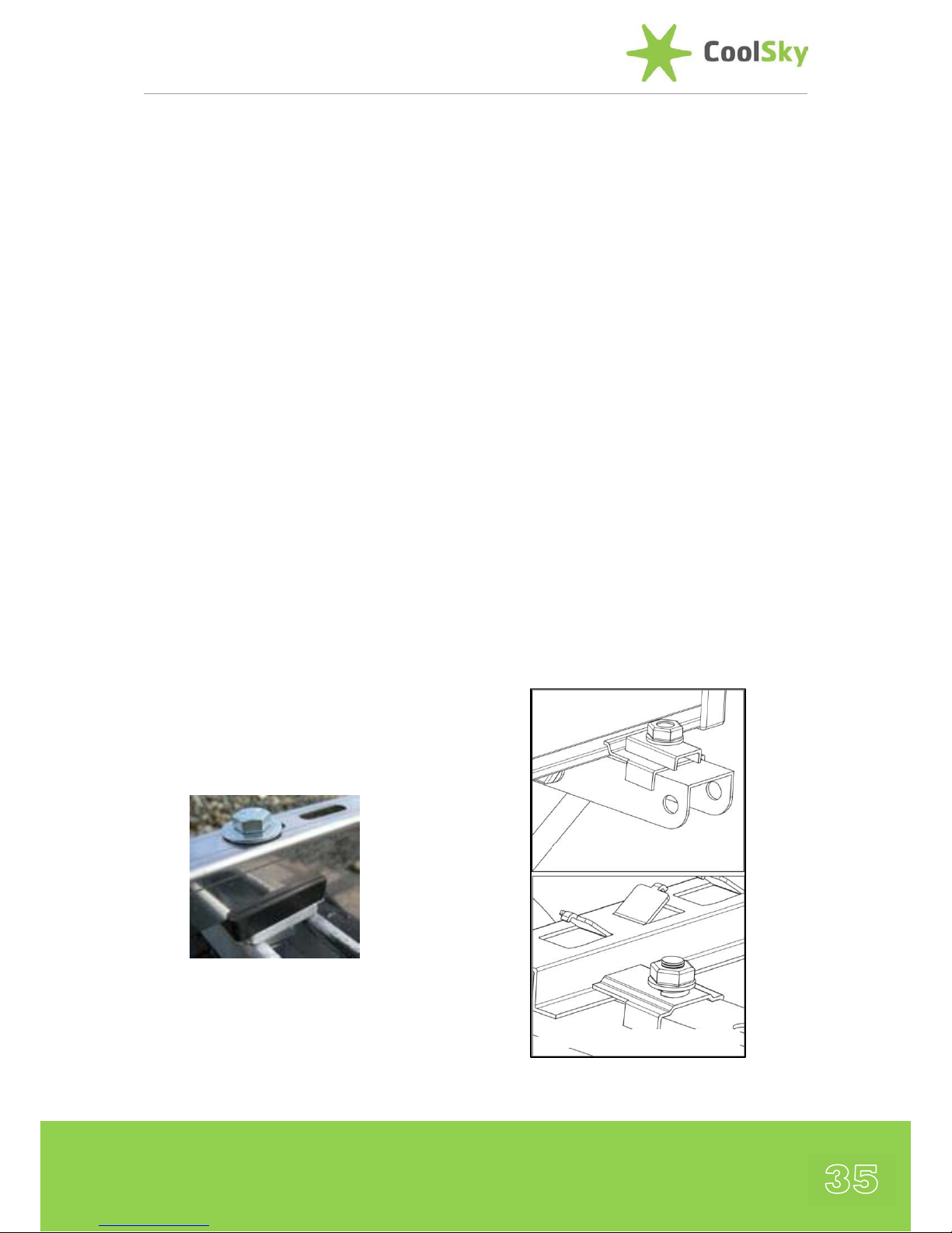
Galvanic Reactions
Zinc galvanized steel roofing or Uni-strut
must NOT directly contact stainless steel as
galvanic reaction between the two metals
can cause premature oxidation of the zinc
coating and the metal underneath. Apricus
offers rubber pads which are perfect for
separating the metals (see image below).
Fasteners
It is recommended that stainless steel
fasteners are used. If using galvanized steel
bolts, separate dissimilar metals using a
nylon or high density EPDM/Silicone rubber
washer.
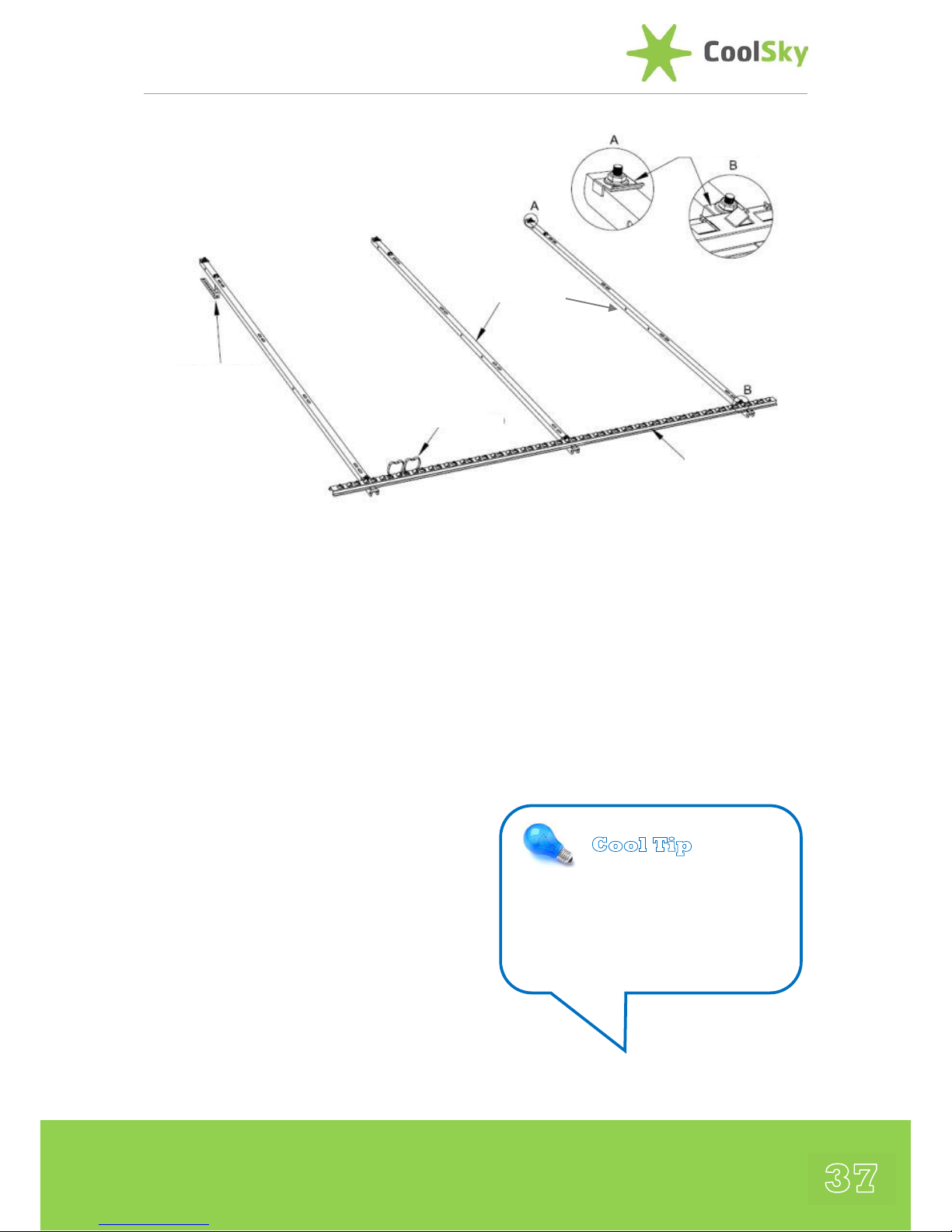
Manifold and Bottom Support Track
Assembly
The Manifold and Bottom Track are secured
to the standard frame channels using special
securing plates. These plates are attached to
the frame channels before they leave the
factory.
They only need to be LOOSENED in order to
allow enough movement to fit the Manifold
and Bottom Support Track in place. The
plates are designed so that while somewhat
loose, they enable the Manifold and Bottom
Support Track to slide left and right for
positioning and allow the standard frame
channels to be easily adjusted side to side to
suit the roof framing layout.
Manifold Attachment
Bottom Support Rail
Page 36

Apricus Installation Manual
36
Tightening Nuts
Once correctly located, the nuts should be
hand tightened ONLY using the supplied
wrench, locking the Manifold and Bottom
Support Track in place. DO NOT use a
power tool or longer hand tool to tighten
the nuts as stainless steel is prone to galling
(cold welding, i.e.), if excessive friction or
over-torqueing occurs (i.e. the nuts can lock
to the shaft before they are completely
seated, if they are over-tightened). The use
of a lubricant on the threads, such as WD40, will also help to prevent issues.
Split washers are supplied to ensure the
stainless steel bolts do not loosen over time.
Inverted Bolts
NOTE: Some bolts are inverted with the nut
on top. This so you can see the threads and
helps prevent you from loosening the bolt
so much that the nut drops off. The bolt
head is prevented from rotating by use of
nut locks (i.e. rectangular washers), removing
the need to use a second wrench
underneath the frame and aiding a quick
and easy assembly process.
Customizing the Frame
The standard frame, together with the
adjustable angle frame kit components can
be adapted to a wide range of different
installation surfaces and situations. Any
modifications to the frame design must be
approved by a licensed engineer and done
with structural integrity in mind, particularly
in high wind areas.
Cool Tip
When drilling the Stainless Steel
always use a good quality drill bit.
Take caution when using power
tools and ‘never’ do any drilling of
the frame whilst on the roof.
Cool Tip
Any modifications to the mounting
frame must be approved for
strength and safety by a licensed
engineer before installation.
Page 37
37
Other System Components
For a typical domestic installation, in
addition to the solar collector, storage tank,
and pump station, some or all of the
following components are also required :
• Solar Expansion Tank
• Copper pipe (straight and/or soft rolled)
with additional insulation or Flexible PreInsulated Stainless Steel Pipe.
• An automatic or manual air vent
• Anti-Freeze based Heat transfer fluid
• Flush & Fill Pumping Cart
• Anti-scald valve
• Various plumbing fittings, valves, drain
valves, etc.
• Scissor lift, cherry picker and/or ladders
and harness equipment for roof work
• Labels and permanent marker to label
system components and flow paths.
Cool Tip
All system components should
be installed in a manner that
allows access for maintenance
and repairs.
Roof Attachment
Strap
Schematic showing the Apricus Standard Roof Frame (this is supplied with the Apricus
Manifold in the same box)
Page 38
Apricus Installation Manual
38
Collector Installation
Flush Mounting on
Pitched Roof
Installation Planning
Carefully plan the location of the collector
frame and plumbing pipes in order to align
with the roof framing members and develop
the shortest pipe run possible to the storage
tank. Any penetrations in the roof or
building shell must be water-tight and sealed
with standard roofing materials and/or
appropriate sealants to avoid leaks and
comply with local building regulations or
requirements.
Securing to Roof
The manifold and bottom support rail can
slide left and right in relation to the frame
side rails, so there is some flexibility when
selecting the location. The frame side rails
should be located so that they lay flat, are
parallel with one another and, if possible,
aligned with the roof rafters. If the frame
side rails cannot be aligned with the roof
rafters, a ‘noggin’ may need to be attached
between 2 rafters to provide an attachment
point. Ensure that any additions or
modifications to the roof structure meet
structural requirement and local building
regulations.
A Horizontal Brace is provided with the
standard frame kit. This gives a useful
indication of the typical spacing between
frame side rails. Additional holes may be
drilled in the horizontal brace to meet
different roofing rafter locations.
The Horizontal Brace component is NOT
structural and is simply to help with
alignment, so it can be removed if it is
incorrectly sized for the roof rafters or it is
not convenient.
Drain-Back System
If installing a drain-back system, the frame
must be rotated slightly to achieve a 2cm
drop per meter to ensure that the manifold
is sloped towards whichever header port will
be the collector outlet (hot), to promote
complete drainage.
Tiled and Slate Roof Installations
Roof Attachment Straps
Roof attachment straps are used for flush
mounting on tiled/slated roofs 2 per
standard side rail. One end of each strap
should be secured to the underside of the
Cool Tip
Ensure that the Assembled Frame is
square so that the tubes align with
the manifold header and the
bottom support track.
Page 39

39
standard frame side rails using the supplied
M8x20 bolts and nut lock assemblies, the
other end to the roof rafter using two
stainless steel coach screws. Once the upper
straps are attached and tightened, adjust the
bottom straps to ensure that they too are
providing support to the frame.
Fragile Slates / High Wind Area
In areas of high wind or where the roof
slates are fragile then the roof attachment
straps should NOT be used.
A rigid solar stand-off bracket (similar to
those shown below) and flashing is
recommended. Care should be taken when
cutting tiles/slates to avoid breakage, as new
tiles/slates may not be readily available. It is
recommended that in such cases a
professional roofer is used.
Manifold and Bottom Track
Attachment
Once the standard frame channels are
secured in place on the roof, the manifold
and bottom track may be attached, taking
care to ensure they are correctly aligned. The
manifold and bottom track will lock into the
frame, secured from above and below with
the attachment plates that are already in
place. Make sure that the Manifold and
Bottom Support Rail are square with the
frame side rails.
To ensure proper tube engagement, each
tube in the Manifold should line up with the
corresponding ‘cradle’ on the Bottom
Support Rail. Each Tube is installed with the
Heat Pipe snugly engaged within the Header
with the opening of the glass tube inside the
Manifold header. The bottom of the tube,
protected by the Rubber Cap, locates in the
‘cradle’ between each set of prongs on the
Bottom Support Rail, where it is held in
place by the Bottom Support Rail Clip.
Mounting on Low
Pitched Roof
If the roof pitch is insufficient, an adjustable
angle roof frame kit (as shown below) can
be used to increase the angle by 27°to 57°.
Adjustable frame kits combine with the
standard frame components to form a
complete frame assembly.
It is recommended that the adjustable frame
kits are completely assembled on the ground
before taking onto the roof – see next
section.
Page 40
Apricus Installation Manual
40
Metal Roof
Installations
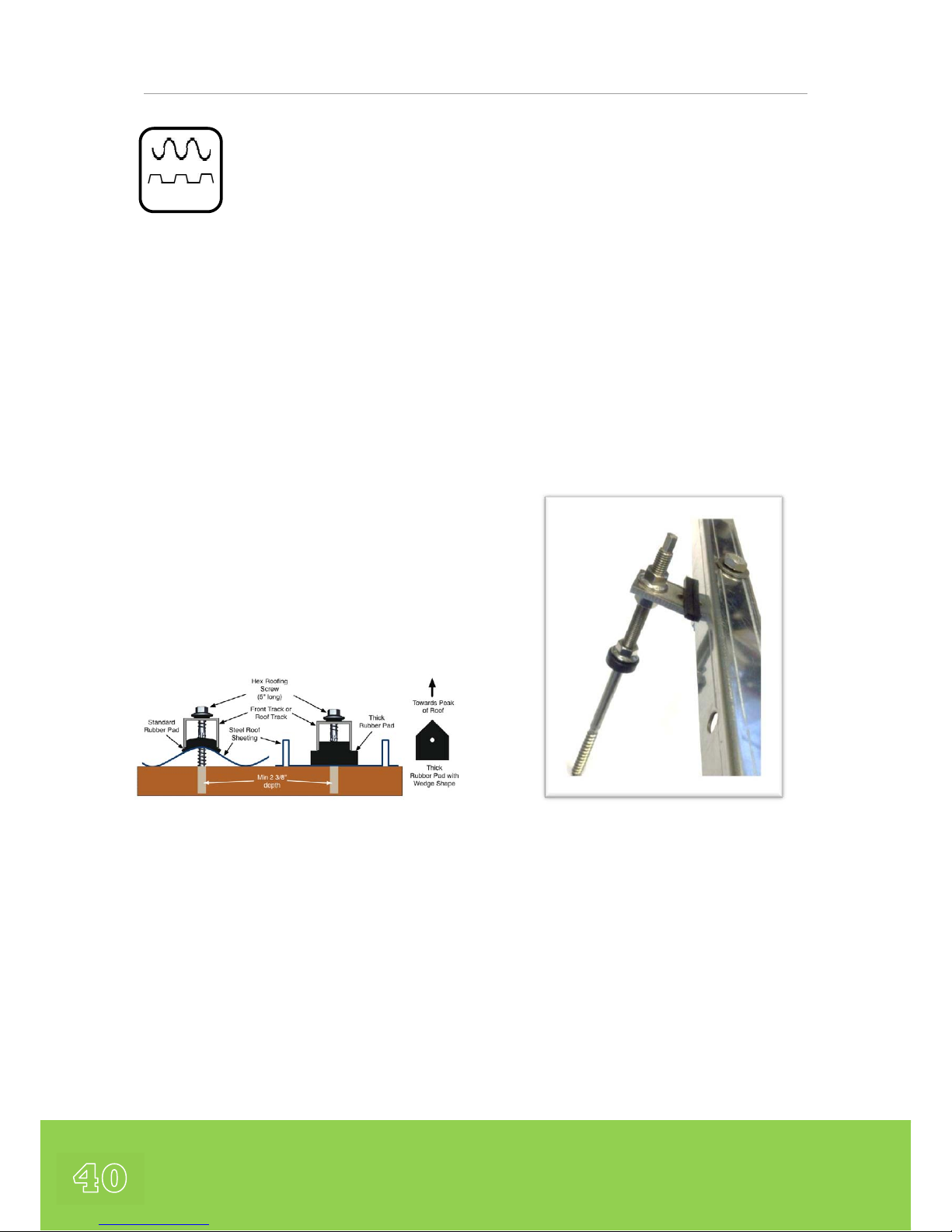
For installation on a corrugated or ridged
steel roof, either a Basic Metal Roof Kit or a
Stand-Off Metal Roof Kit can be used to
secure the collector to the roof.
The Basic Metal Roof Kit
This kit consists of Rubber Sealing Pads that
are used to separate the frame from the roof
and also to seal the hole. Addition of some
silicone sealant or similar roof sealant
beneath the pad and inside the hole is
required thereby allowing the rubber pad to
form a tight seal against the roof, preventing
any water ingress. Three (3) attachments per
track are required.
The Stand-Off Metal Roof Kit
For installations where longer bolts may be
required to account for the height of the
ridges such that the required depth of
penetration into the rafter is achieved, or
there is a desire to hold the collector frame
away from the roof structure, the Stand-Off
Metal Roof Kit is suitable.
Each kit consists of 4 or 6 large hanger bolts
M10 x 250mm with integral rubber seals,
attachment plates, rubber pads and the
required nuts, bolts and washers for
attaching to the collector frame side rails.
Addition of some silicone sealant or similar
roof sealant beneath the pad and inside the
hole is required thereby allowing the rubber
pad to form a tight seal against the roof,
preventing any water ingress. Two (2)
attachments per track are required, thereby
needing 4 for a 20-tube collector or 6 for a
30-tube collector.
Page 41
41
Flat Roof
Installation
The high angle frame is adjustable and
appropriate for installations on flat surfaces
and provides adjustment from 27°-57
°
. The
high angle frame kit combines with the
standard frame components to form the
complete frame assembly.
The high angle frame is supplied with Round
Feet that are also suitable for attachment to
concrete ballast on a flat roof.
For additional strength and support a rear XBrace is supplied. The X-Brace has a series of
elongated holes to allow adjustment of the
location of the legs. If further adjustment is
needed, additional ∅9 mm holes may be
drilled using a good quality drill bit.
Assembly of the Support Frame
When undertaking an installation that
requires an adjustable angle roof frame kit
(such as on a flat roof or a low pitched roof)
it is recommended that the frame is
completely assembled on the ground on a
clear flat area. The collector frames are
relatively light and can easily be carried onto
the roof once assembled. Assembling on the
roof is both dangerous and makes it easy to
lose bolts and nuts that may roll away.
Frame Feet Anchoring
Frame feet should be bolted to the
installation surface using 8 mm diameter
stainless steel bolts or a similarly sturdy
fastening method. (Galvanized bolts should
be NOT be used as these can result galvanic
corrosion).
The surface or concrete block must be
strong/heavy enough to withstand load
during high winds. Consult a professional
structural engineer for design requirements.
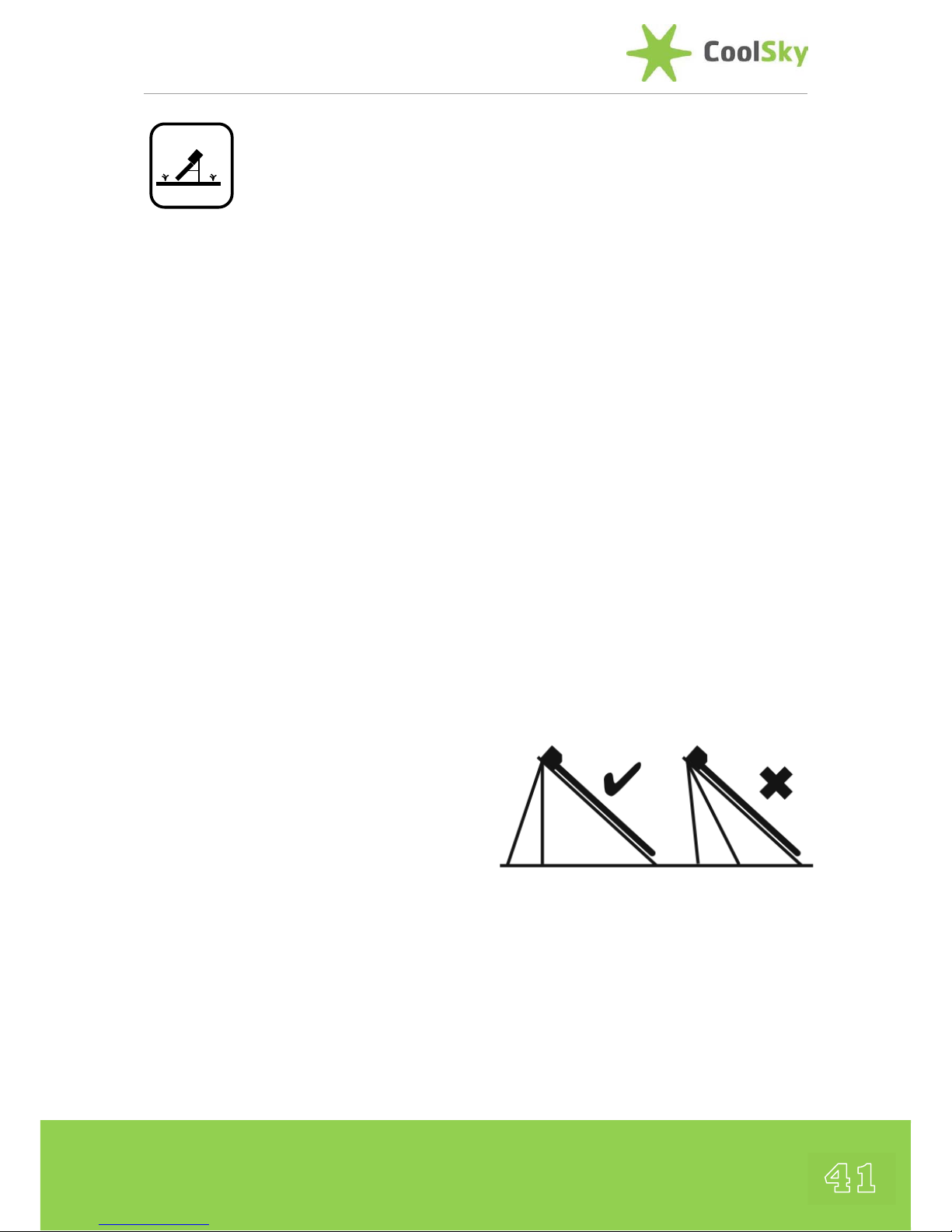
Adjusting Frame Angle
The rear legs of the high angle frame
comprise two interlocking pieces (top and
bottom leg), which allow the length of the
rear leg to be adjusted, thus changing the
collector angle from between 27
o
and 57o.
The rear legs must never be positioned
greater than a 90
o
angle (perpendicular) with
the roof surface, meaning the legs must be
behind the position of the manifold, not in
front. See diagram to below.
Page 42

Apricus Installation Manual
42
Rear Legs
Each rear leg has two pieces, a top and a
bottom, which allows them to be adjusted.
The two pieces must always be joined
together by 2 bolts through two sets of
holes each in each leg for structural support.
Lower Angles
If an angle less than 27
o
is required the low
angle frame kit should be used which
provides an installation angle of 12
o
.
Higher Angles
If an angle greater than 57
o
is required, the
mounting points of the rear feet may be
raised. Raising the angle greatly increases
the horizontal force during high winds and
may require additional structural and/or
hardware upgrades. Consult a building
engineer for design requirements.
Standard Frame
Support Rail
Standard Frame
Side Rail
Diagonal Brace
Top Rear
Leg
Bottom Rear Leg
When fitting place the large metal washers
between the inner wall of the side rail and
the outer face of the diagonal brace to
ensure a tight fit
Adjust location of diagonal
brace to chosen angle
Apricus A-Frame
Supplied with
Round Fixing Feet
as Standard
Optional Rubber Pad for
attaching to metal roofs
to eliminate galvanic
corrosion risks
Page 43
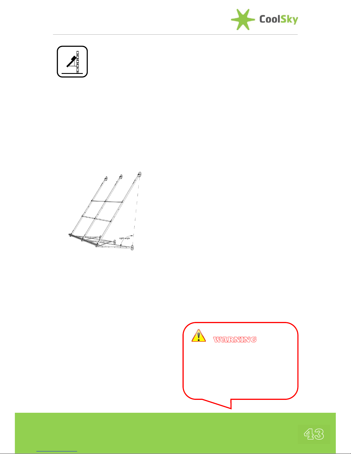
43
Wall / Façade
Installations
The high angle frame kit may be used for
Wall / Façade Installations. The legs are
reversed so that they attach to the bottom
of the standard frame side rails rather than
the top. The legs should be position
perpendicular to the wall and are adjusted
and secured in the same manner as the Flat
Roof Installation detailed in the previous
section.
Surface Attachment
The method used for attachment to the wall
will depend on the wall material.
- The round feet can be secured with
stainless steel expansion bolts for
attachment to brick or concrete surfaces
- Stainless steel coach screws of at least
8mm diameter or greater with high
sheer strength that can penetrate into
the wall framework can be used with
wood or synthetic boarding surfaces.
Wall Strength
Always consider the weight of the collector
and the structural integrity of the wall. If the
wall construction is not suitable for the load,
it will be necessary to reinforce the wall
frame accordingly. Consult a building
engineer for design requirements.
Recommended Angle
Ideally, do not install the collector beyond an
angle of 80
o
(close to vertical) otherwise
heat pipe operation will be impaired by 10%
or greater. Installing vertically is permitted
and will not void the warranty, but
performance will be reduced.
Safety Considerations
If installing the collector on a wall above a
walkway, keep in mind the danger of broken
glass that could fall on pedestrians, if the
tubes were ever damaged. (E.g. during an
extreme storm due to flying debris or tree
branch falling on the collector). It may be
necessary for a barrier of to be installed
below the collector to catch any falling
materials, such as a clear roofing material.
WARNING:
For collectors installed above a pedestrian
area, take appropriate measures to
minimise injury risk in case a broken tube
or glass fell onto the ground or people
below.
Page 44

Apricus Installation Manual
44
Connection to Plumbing
Plumbing Connection
Once the frame has been mounted and the
manifold attached, the manifold header may
be connected to the system plumbing.
Delayed Commissioning
If the collector is to be installed (including
evacuated tubes) prior to plumbing
connection (e.g. on new house), high
temperature resistant covers (aluminum foil)
should be placed over the header inlet and
outlet to prevent any contaminants (bugs,
spiders, leaves, dust) entering the header.
The solar collector will not be damaged by a
period of dry stagnation that lasts less than
14 days.
If the collector is to be left for any significant
period of time before being commissioned it
is recommended that the collector is covered
with an appropriate tarpaulin. Ensure that
the tarpaulin is secured to the roof fixings –
DO NOT secure any cover or tarpaulin to the
glass tubes as this can result in damage /
breakage of the glass under high wind
conditions.
✖ Damage to collectors and other
components incurred by extended dry or
wet stagnation is not eligible for warranty
claims.
Pipework
Suitable Pipe Materials
Only the following materials are
recommended for use with High
Performance Evacuated Tube Solar Collector
Systems, as follows :
- Flexible Stainless Steel Pipe
- Copper Tube (hard or soft coiled)
Plastic Pipes (PEX) and Galvanised Pipes
should NEVER be used in a solar thermal
system
All pipework in the solar loop should be
suitable insulated in compliance with local
building regulations.
Insulation
Insulate Piping
Ensure all piping running to and from the
manifold is appropriately insulated with a
high quality insulation that complies with
local building regulations in terms of its
thermal conductivity and thickness required.
Heat loss from the piping can be significant
so particular attention should be taken to
insulate any possible points of heat loss,
particularly on outdoor piping.
Page 45

45
Seal the Insulation and Sensor
Port
Ensure the insulation is tight against the
manifold casing, preventing loss of heat from
the inlet and outlet. In order to prevent
water from entering the temperature probe
port and/or in between the piping and
insulation foam, a high quality silicone
sealant should be used to form a water-tight
seal. This is also important to avoid water
running down under the insulation along the
copper / stainless steel pipe into the roof
space.
Protect Insulation
EPDM (foam) insulation that is exposed to
direct sunlight should be protected against
UV related degradation. CoolSky supply
Stainless Steel Flexible Pipework that is preinsulated with high-grade EPDM Insulation
with UV Protective sheath.
Page 46

Apricus Installation Manual
46
Installation of the Tubes
The Apricus solar collector is a simple “plug
in” system. The heat pipe and evacuated
tube assembly just needs to be inserted into
the manifold. The contact between the heat
pipe condenser/tip and heat pipe port in the
header needs to be tight in order to ensure
good heat transfer. Under normal use, once
the heat pipes are installed they should
never have to be removed.
Heat Pipe Preparation
Do not remove the tubes from the box
and/or expose the tubes to sunlight until
ready to install, otherwise the heat pipe tip
will become hot enough to cause serious
skin burns. The outer glass surface should
not become hot.
Heat Pipe Frost Protection
Apricus Heat Pipes contain a small amount
of copper powder, which aids in heat transfer
and provides freeze protection within the
heat pipe itself. To ensure that the powder
is at the bottom of the heat pipes, where is
needs to be, before installing the tube and
heat pipe, they should inverted (condenser
end down), returned upright (condenser at
top) and then shaken up and down a few
times to ensure the powder has all returned
to the bottom. This should be done at
ground level.
Damaged Tube
If an evacuated tube is damaged for any
reason (E.g. knocked heavily or dropped), it
will need to be replaced.
Never throw heat pipes away, as they are
very sturdy and will not be damaged even if
the glass tube has been broken. They can
be kept as spares, or inserted into plain
spare evacuated tubes to provide a new fully
functional tube.
WARNING:
Safety glasses and leather gloves
must be worn at all times when
handling evacuated tubes and heat
pipes. Never touch the inside of
evacuated tubes or the heat pipe tip
after exposure to sunlight.
Cool Tip
Activate the Frost Protection by
inverting the tubes, returning to an
uprights position and shaking.
Cool Tip
Do not install the tubes until system
plumbing is completed, the solar loop
is charged, the pump and controller
are operational and fluid is currently
circulating (set controller pump
function to ON).
Page 47
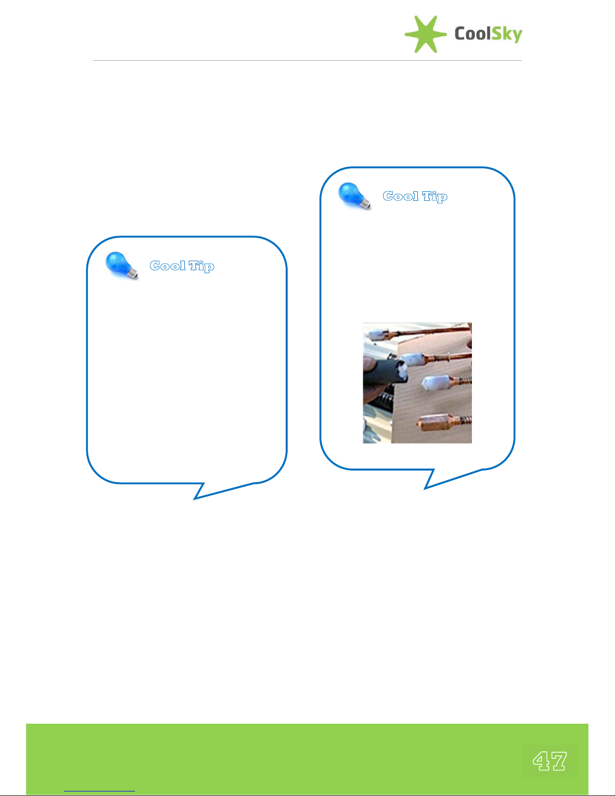
47
Application of Heat Transfer Paste
The Apricus Manifold box is supplied with a
small tube of Thermal Heat Transfer Paste.
This is a specially formulated paste that is
designed to aid the conduction of thermal
energy and is used to lightly coat the Heat
Pipe Condenser to enhance its thermal
conduction characteristics.
While holding the spring plate in place, pull
the heat pipe out of the evacuated tube by
about 8 cm.
Apply a thin layer of the heat transfer paste
around the body of the heat-pipe condenser
(not the top round end).
This is easiest to do using a short length of
insulation pipe. Squirt some of the heat
transfer paste into the insulation, the use to
coat each heat pipe tip with a thin layer and
remove any excess from the tip. Using this
method half a tube can coat 30 tubes.
Heat Pipe and Evacuated Tube
Insertion
Lubricate the top outer surface of the
evacuated tube with a small amount of
water. This facilitates easy insertion past the
manifold rubber ring seal. A small pump
spray bottle is the best method for carrying
and applying the water.
NOTE: DO NOT SPRAY WATER INTO THE
EVACUATED TUBE
Cool Tip
Apply the heat transfer paste
using a short length of the
insulation – squirt the paste into
the insulation and use to thinly
coat the surface of each
condenser.
Cool Tip
Before use, the Tube of Heat
Transfer Paste can be placed (cap
downward) in a glass of warm
water to allow the powder to re-
mix through the paste as it may
have settled during transport. This
will ensure optimal thermal
performance and will also make
application and heat pipe insertion
easier as the paste becomes thinner
Page 48

Apricus Installation Manual
48
Insert Tube
While ensuring the metal spring plate is
sitting in the mouth of the evacuated tube,
firmly hold the evacuated tube and guide
the heat pipe tip in past the manifold rubber
seal and into the heat pipe port.
Ensure the heat pipes are at the TOP DEAD
CENTER of the evacuated tube and therefore
aligned correctly with the heat pipe port.
Insert Tube - Rotating
Using no more than a 1/8
th
turn left and
right twisting action, push the evacuated
tube up into the manifold. The neck of the
evacuated tube will push against the spring
at the base of the heat pipe tip, forcing it
fully into the port.
DO NOT over rotate the tube when inserting
otherwise the heat pipe will be turned out of
alignment with the top of the tube, which
will prevent proper heat pipe operation.
Correct Insertion Depth
The heat pipe and evacuated tube are fully
inserted once the black coating of the
evacuated tube has disappeared up into the
manifold and no clear glass above the
coating is visible.
Securing the Tube
Position the rubber end-cap so it is aligned
with the corresponding ‘cradle’ in the
bottom support rail and the Apricus Logo
facing upwards. This ensures that drain holes
in the cap are properly positioned. It DOES
NOT have to be pushed hard up on the
tube.
As each tube is inserted secure the tubes to
the bottom support rail using the stainless
Cool Tip
A small amount of water can be used
at the tube of the glass tube, on the
outer surface, to facilitate easier
insertion past the manifold rubber
ring seal.
NOTE : DO NOT LET ANY WATER GET
INTO THE EVACUATED TUBE
Page 49

49
steel securing clips as shown in the picture
above. The bottom of the tube should sit so
that the groove on the rubber cap lines up
with clip point on the bottom track. Line up
the clip with the hook on the bottom
support rail and push down over the rubber
cap.
Removal of the Securing-Clip
The clip can be removed by using a
screwdriver or needle nosed pliers to pull
each side of the clip down and outward.
Very little force is required.
Post Installation Cleaning
Clean each evacuated tube with a fluid glass
cleaner and cloth then dry clean with
newspaper.
.
Page 50

Apricus Installation Manual
50
Commissioning The System
Ensure Expansion Vessel Pressure has been
re-set correctly before filling the system.
Filling the System
It is recommended that the system is filled
with the Anti-Freeze Fluid using a
professional Flush & Fill Cart (such as that
shown in the picture below).
When used correctly these stations ensure
that all the air is purged from the system
during the filling process.
In addition, it is also essential to have either
an automatic or manual de-aerator / airscoop so that any accumulation of air in the
system can be regularly vented. The CoolSky
Pumping stations are supplied with a readyfitted manual air-scoop to allow for further
air bleeding of the solar loop if required.
Commissioning Method
Connect the Flow Hose from the Flush and
Fill Cart to the Filling Valve (1) and open the
valve.
Connect the Return Hose to the Drain Valve
(2) and open the valve.
Close the Restrictor Flow Valve (3) so that
the slot is in a horizontal position.
Open the Cold Check Valve (4) by turning so
that the 45° indicator is facing upwards.
Open the Hot Check Valve (5) by turning so
that the 45° indicator is facing upwards
Pour the Anti-Freeze fluid into the Flush and
Fill Cart and then fill the solar system (follow
the manufacturer instructions for the
Cool Tip
Expansion Vessel Pressure should be
re-set to 0.3 Bar less than the Cold
Fill Pressure.
Cool Tip
The Cold-Fill Pressure of the Solar
System should be :
1.3 + (0.1 x Static Height)
Where the Static Height is in
Meters.
1
2
3
4
5
6
7
Flush & Fill
Cart
Page 51

51
operation of the solar cart). The Solar System
should not be flushed nor pressure tested
with water only as it is not always possible
to completely drain all the water from the
system upon completion and this can result
in an increase freezing risk of the system.
The Solar System should be flushed using
the Flush & Fill Cart for a period of at least
15 minutes to ensure the fluid is completely
deaerated. During this operation it is good
practice to momentarily open the Restrictor
Flow Valve (3) to ensure any trapped air in
this region is cleared.
After flushing for 15 minutes the following
procedure should then be undertaken :
Close the Drain Valve (2) whilst the Flush
and Fill Cart is still running. Carefully monitor
the system pressure on the Pressure Gauge
(6) and allow to increase to the
recommended cold-fill pressure.
Once the recommended cold-fill is reached
in the system the Flow Valve (3) should be
shut and the power to the Flush & Fill cart
turned off.
Monitor the system pressure gauge for any
drop in pressure that may indicate a leak in
the pipework.
Open the Restrictor Flow Valve (3) so that
the slot is in a vertical position.
Close the Cold Check Valve (4) by turning so
that the 90° indicator is facing upwards (i.e.
the gauge is now in the correct orientation).
Close the Hot Check Valve (5) by turning so
that the 90° indicator is facing upwards (i.e.
the gauge is now in the correct orientation).
Manually vent any air in the system from the
Manual Vent Port (6)
The Solar Loop Circulating Pump should
then be run on its highest speed using
pump speed selector (7) for 15 to 30
minutes. Refer to The Solar Controller
Operation Manual to run the pump in
continuous mode. (Remember to return the
controller to automatic mode after
commissioning).
If necessary manually vent any air in the
system from the Manual Vent Port (6)
Select the required pump speed for normal
operation using the pump speed selector (8)
and regulate the flow using the Restrictor
Cool Tip
Set the Flow Rate through the
collector array to :
0.1 litre / minute / tube
That is :
1 litre / minute for 10-tubes
2 litres / minute for 20-tubes
3 litres / minute for 30-tubes
Page 52

Apricus Installation Manual
52
Flow Valve. The Flow rate can be read on the
sight glass.
Remove the flush & fill hoses from the
pumping station and attach closing caps
onto the valves to seal them.
Re-Check System for leaks.
Ensure all valves are in operational positions.
Ensure Solar Controller is set to Automatic
Operation.
Post Installation
Collector Operation
Once all the tubes are installed and the
system is fully commissioned, the solar
collector will begin to produce heat after a
5-10 minute warm up period when the sun
is shining. Check the controller and pump for
correct operation and adjust settings as
required. Make sure that you have changed
the controller setting from ON to
AUTOMATIC.
Clean Up
Once the system is confirmed as operating
correctly, ensure the installation site is
cleaned of all rubbish that should be
recycled, whenever possible.
Chemicals, paints and heat transfer fluids
must be disposed of in line with their MSDS
guidelines provided by the manufacturer and
in line with local regulations.
Page 53

53
Maintenance & Repair
Once installed and operational the solar
collector is virtually maintenance free. Other
system components such as the pump, heat
transfer fluid require periodic inspection and
may need to be replaced in the future.
Please refer to the documentation provided
by the manufacturer of these other
components.
WARNING
Apart from maintenance specifically outlined
as “OWNER”, any maintenance or repair
MUST ONLY be performed by authorized
persons. At no time should any inspection or
maintenance be performed by the
homeowner, if it involves climbing on the
roof or any potentially unsafe behaviour. The
solar collector warranty will be void, if nonauthorized persons attempt to maintain or
repair the solar collector or associated
system components. The solar system
operates at high pressure and high
temperature and can cause damage to
property and severe personal injury, if not
correctly operated and maintained.
Periodic inspections by an authorized
Apricus installer is recommended to ensure
optimum system operation.
The following maintenance may ONLY be
completed by AUTHORIZED PERSONS
Broken Tube
If a tube breaks, it should be replaced as
soon as possible. Whilst the system will still
operate normally and safely with a broken
tube, it will be at a slightly reduced level of
performance. To ensure maximum collector
performance any broken tubes should be
replaced.
Always wear safety goggles and gloves when
handling broken glass and clear away any
broken glass immediately to prevent injury.
To replace a tube
Remove the tube clip(s), slide broken tube
out and carefully pick up any glass pieces.
Avoid touching the glass wool insulation
with bare hands, as it can cause mild skin
irritation.
Remove the heat pipe and insert a new
evacuated tube & heat pipe.
If the heat pipe is not easily removed (as is
commonly the case), it can be left in place
and a new evacuated tube inserted by
carefully guiding the heat pipe down the
groove between the evacuated tube inner
wall and heat transfer fin.
Insulation
The pipes running to and from the collector
should be completely insulated. Insulation
should be checked periodically (at least once
every 3 years) for damage or gaps, especially
exterior EPDM foam insulation.
Page 54

Apricus Installation Manual
54
For any insulation that has external exposure
to weather conditions ensure that the
protective cover is in good condition,
replacing if required.
Heat Transfer Fluid
Heat transfer fluids that are exposed to
stagnation temperature may break down
over time, which will cause the fluid to
become acidic and loose anti-freeze
properties.
The fluid will generally become “sludgy,”
which can reduce circulation efficiency.
Ideally, heat transfer fluid should be
inspected and tested annually, but least once
every 3 years. The following checks should
be completed on the Thermal Transfer Fluid :
Check for cloudiness or sludging that would
indicate fluid breakdown.
Check pH, should be within the range
specified by the manufacturer.
Use an Anti-Freeze tester to check freeze
protection level.
If the fluid shows signs of degradation it
should be replaced.
If the system is severely clogged up with
‘sludgy’ degraded glycol it may be necessary
to clean the system using a proprietary solar
cleaning fluid prior to re-filling the system.
Heat Transfer Fluid – Top Up
If there has been a drop / loss of pressure in
the solar loop it will need to be recharged /
re-pressurised.
The solar system should only be topped-up
with the SAME glycol fluid as was used to
originally fill the solar loop.
Water must NEVER be used to top-up the
system as this can result in the dilution of
the anti-freeze protection and leave the
system susceptible to freezing.
Draining the Collector
During system maintenance or in draining
the collector manifold may be required. If
the building is going to be vacant for longer
than 45 days at a time, the system must be
drained and the collectors covered with a
tarpaulin.
Any fluid drained for the system that is
intended for disposal should be disposed of
in line with local regulations.
Freezing
As freezing conditions are always a
possibility in the UK and Ireland (particularly
in the winter months) CoolSky always
recommend the use of a Solar Thermal AntiFreeze Fluid in the Solar Loop.
Whilst some system designs try to
accommodate for freezing conditions with
special functions in the system controllers, it
is not unusual for periods of heavy frost in
the UK and Ireland to be accompanied by
power outages. Hence, any Frost Protection
Functions in control units will not operate,
thereby exposing the collector to a freezing
risk.
Page 55
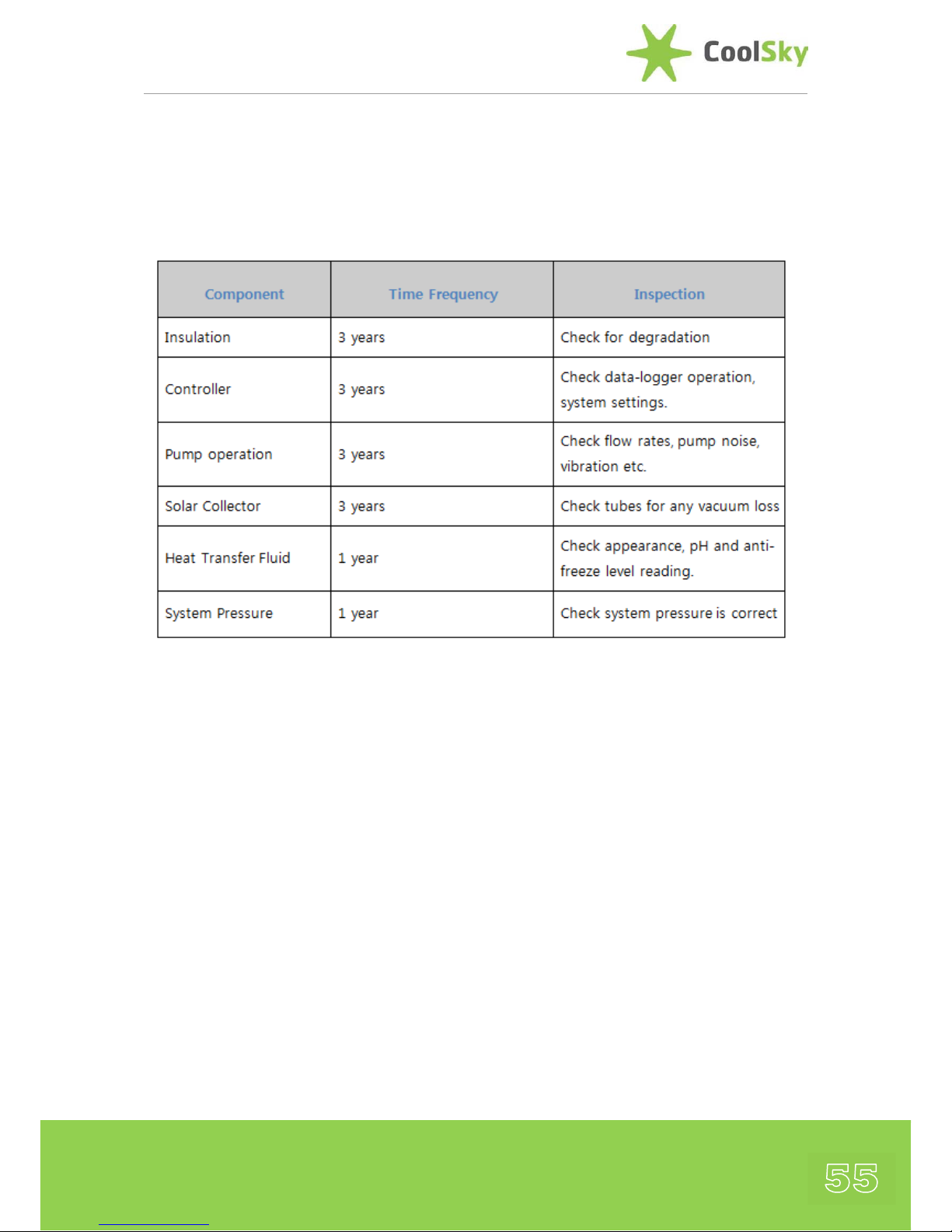
55
Maintenance Schedule
It is recommended that as a minimum the
following maintenance schedule is followed:
Other Components
Other parts of the system such as the
storage tank and the back-up heating /
boiler should be serviced and inspected
according to their specific manufacturer’s
maintenance guidelines.
Page 56
Troubleshooting Guide :
Problem
Possible Cause
Suggested Solution
Pump not
coming ON
during good
solar radiation
conditions
Temperature
Sensors not
working properly
● Check that sensors are installed correctly :
- Are they wired to the correct terminal blocks in the solar
controller
- Ensure wires are secure
● Check that sensors wires are not damaged
● Check the Resistance (Ohm) valve of the sensors and confirm
with PT1000 Temperature chart (as a guide 0°C is 1000 Ohm and
100°C is ~1385 Ohm)
Controller
Settings Incorrect
● Check controller is set to Automatic Operation
● Check maximum tank and collector settings
Controller Max
Temperature
Setting has been
reached
● Check maximum tank and collector settings
Pump is
cycling ON
and OFF
during good
solar
conditions
Partial Shading of
Collector
● Check collector location for possible shading
Excessive System
Flow Rate
● Reduce flow rate by adjusting restrictor screw on the flow meter
● Reduce the Pump Speed (Select Slower Speed)
Controller
Settings Incorrect
● Check if differential (dT function) is correct. dTMin may be set too
high. Trying reducing to 2°C.
Pump is
always ON
even during
minimal solar
radiation
Insufficient Flow
Rate
● Check flow gauge for proper flow rate
● Adjust restrictor screw on flow meter
● Check that all isolation valves are open
Air-Lock in Piping
System
● Release air from air vent on pumping station
● Run pump at highest speed setting for a period of time and then
release any accumulated air from air vent on pump station (return
pump speed to normal settings)
Sensor Location
too Low
● Bottom Cylinder sensor (typically T2) should be slightly above the
level of the solar flow port on the cylinder. If below the flow port,
the pump may run continually.
Controller
Settings Incorrect
● dTMin may be set too low. Increase by 2 or 3°C.
Page 57

57
Troubleshooting Guide (continued) :
Problem Possible
Cause
Suggested Solution
Poor Solar
Heating
Contribution
(Compared to
previous
output at
same time of
year)
Cont’d
Increased hot
water
demand
● Check if hot water demand from the property has increased which
would reduce the % of contribution from the solar collector even with
the same level of output
Insufficient
flow rate
● Check flow gauge for proper flow rate and check pump operation if flow
rate is insufficient
● Adjust restrictor screw on flow meter to increase flow rate
● Check heat transfer fluid pH, Colour and viscosity as it may need to be
flushed and replaced
Partial
Shading of
Collector
● Check collector location for shading or accumulation of snow. If
accumulation of snow is an issue the ensure installation angle is
increased to least 45°.
Heat Loss
from Pipes
● Check that insulation is still in good condition with no exposed hot
pipes
Damage to
Evacuated
Tubes
● Check that evacuated tubes are all intact and that the getter at the
bottom of the tubes remains silver coloured
Heat Pipes
Not
Operating
● Check that heat pipes are making good contact in the manifold header
and are hot at the condenser tip
Scale build
up in Plate
HeatExchanger
● Follow manufacturers recommendations for dealing with scale build-up
Thermosipho
ning
● System may be reverse thermosiphoning at night. Ensure check valve in
pump station is working
Insufficient
Pump Run
Time
● Not Applicable for Variable Speed Pumping
● For Standard ON/OFF Pump Operation ensure the pump is running for
long enough to transfer the heat from the collector to return to the
cylinder – carefully monitor the return line to check. Reduce dTMin value
slightly if required.
Page 58

Apricus Installation Manual
58
Troubleshooting Guide (continued) :
Problem Possible
Cause
Suggested Solution
Poor Solar
Heating
Contribution
(Compared to
previous
output at
same time of
year)
Pump
Cycling too
Long and
Dissipating
Heat
● dTMin value set too low
● T2 Sensor (Bottom Tank) too low in tank and always reading cold water
– move to correct location
Excessive
Tank Heat
Losses
● Insulate both the hot and cold water pipes connected to the storage
tank. A check valve (spring not flap) on the cold and hot pipe in close
proximity to the tank will help reduce heat migration up the pipe
● Insulate and exposed fittings and valves on the storage tank. DO NOT
impair the operation of the PTRV.
Not Enough
Hot Water
Back-Up
Heating
● Is back-up heating system functioning normally.
Faulty
Temperature
Mixing Valve
● Check operation of Temperature Mixing Valves
Increased
Hot Water
Demand
● Has demand in the property for hot water increased
● May need installation of larger capacity boiler
● Boost settings on controllers may need revised
● Larger storage tank / collector array may be required
Intermittent
short bursts
of cold water
when
showering
Faulty
Temperature
Mixing Valve
● Check operation of Temperature Mixing Valve.
Pump
Running at
Night
Temperature
Sensors not
working
properly
● Check that sensors are installed correctly :
- Are they wired to the correct terminal blocks in the solar controller
- Ensure wires are secure
● Check that sensors wires are not damaged
● Check the Resistance (Ohm) valve of the sensors and confirm with
PT1000 Temperature chart (as a guide 0°C is 1000 Ohm and 100°C is
~1385 Ohm)
Page 59

59
Troubleshooting Guide (continued) :
Problem Possible Cause Suggested Solution
System
Operation is
Noisey
Air in System
Piping
● Release air from air vent on Pumping Station
● Purge system of air – run on maximum pump speed for a period of
time, then release air from manual air vent on pump station. Return
pump to normal speed settings.
● If above operations have not been successful the system may need
purged using Flush & Fill cart to remove entrapped air
Fluid
Dumping
from the
Pressure
Relief Valve
on the
Pumping
Station
System OverPressurised
during
installation
● Confirm cold fill pressure (in Bar) is in agreement with
guideline of 1.3 + (0.1 x Static Height) where static height is in
Meters.
- If over-pressurised release some fluid pressure (only under cold
conditions)
Faulty Expansion
Tank
● Replace expansion tank on the pumping station.
Faulty Pressure
Relief Valve
● Replace the Pressure Relief Valve
The following basic maintenance or inspection MAY be completed by the HOMEOWNER
Page 60

Apricus Installation Manual
60
Home-Owner Maintenance
Cleaning
In most cases, periodic rain will keep the
evacuated tubes clean. If particularly dirty,
they may be washed from a safe location
with a high-pressure water spray. If the
collectors are located where they are easily
and safely accessible, a soft cloth and warm,
soapy water or glass cleaning solution may
be used.
During autumn, leaves may accumulate
between or beneath the tubes. Please
remove these leaves regularly to ensure
optimal performance and to prevent
accumulation of ignitable material (if in high
fire risk area). The solar collector will NOT
cause the ignition of flammable materials.
Such cleaning may only be completed by the
homeowner if the tubes are easily and safely
accessible.
Inspection
If there is any problem with the system, the
installer will, generally, ask the homeowner
to inspect various portions of the system
before making a service call. The following
inspections may be performed by the
homeowner, ONLY if they are easily and
safely accessible.
a) The pump station foam casing may be
removed (pulled toward you and off) to
check the following system information:
i) Pressure gauge reading
ii) Temperature gauge reading
iii) Pump operation (i.e. sound)
iv) Flow meter reading
v) Visual Inspection of Fluid through
the Flow Meter Sight Glass
b) Visual check for degradation of pipe
insulation
c) Visual inspection of solar collector tubes
d) Any fluid blow off into Catchment
container
Page 61
61
Decommissioning Instructions
Decommissioning of the Solar System MUST
only be undertaken by a competent and
trained person due to the high temperatures
(>150 ºC) and high pressures (> 6bar) that
can exist within the solar loop.
The system should be decommissioned
when cool and ideally in low light conditions
– early morning on a cloudy day would be
ideal.
All electrical units should be isolated from
the mains power supply before removing the
power, sensor and earth connecting cables.
The collector loop can be drained from the
drain valve in the solar loop. Be AWARE that
hot glycol that may be in the solar loop.
Carefully drain all the fluid from the solar
loop should and gather in a suitable
container and dispose of in accordance with
local regulations.
Once the collector is fully drained the pipework can be disconnected from the system
and the collector can be dismantled and the
components set aside for recycling.
End of Life Recycling
Once the Apricus Solar Collector has reached
the end of its usable life, it can be efficiently
recycled. Below are the main materials used
in the solar collector, all of which can be
readily recycled where facilities exist.
Aluminium
Manifold casing and heat transfer fins
Silicone Rubber
Tube caps, header inlet & outlet seals, tube
seals and manifold end covers
Glass Wool
Insulation within manifold
Copper
Manifold header pipe and heat pipes
Borosilicate Glass
The Evacuated Tubes
Stainless Steel
Mounting Frame, tube clips, nut and bolts,
and evacuated tube support spring
Galvanized Steel
Heat transfer fin clips
Paper
Boxes and tube supports
Polyethylene
Packing bubble wrap
Page 62

Apricus Installation Manual
62
Product Registration
Customers / Installers are strongly
recommended to register their installation
with Apricus. This can be easily done online
at www.apricus.com and following the links
to
Product Registration
.
A detailed installation record is then
maintained by Apricus that will greatly help
with any future warranty claims or servicing
of your system.
Disclaimer
Whilst every effort has been taken to ensure the
accuracy of the information contained within this
document CoolSky Ltd makes no representations about
the suitability of the information contained herein for
any purpose. The information provided herein is
provided ‘as is’ without warranty or guarantee of any
kind. CoolSky Ltd disclaims all warranties and conditions
with regard to this information, including all implied
warranties and conditions of merchantability, fitness for
a particular purpose, title and non-infringement. In no
event shall CoolSky Ltd or any subsidiaries or any
suppliers be liable for any special, indirect or
consequential damages or any damages whatsoever
resulting from loss of use, data or profits, whether in an
action of contract, negligence or other tortious actions,
arising out of or in connection with the use of
information contained in this document.
The information and graphics contained in this
document could include technical inaccuracies or
typographical errors. Changes are periodically made to
the information herein. CoolSky Ltd may make
improvements and / or changes in the product(s) and /
or the program(s) and / or the procedure(s) described
herein at any time.
Page 63

63
Glossary of Terms
Temperature Mixing Valve (TMV)
A valve installed between the solar water
heating system and the fixtures to
automatically mix the hot water with cold
water to achieve a safe outlet temperature of
50
o
C. A mixing valve must stop all hot water
flow if there is a loss of either cold or hot
water supply.
Closed Loop
A system that, typically, has an anti-freeze
heat transfer fluid circulating through a
closed, pressurized solar collector piping
loop. This “freeze resistant” fluid is
separated from the mains pressure water by
a heat exchanger and typically should also
contain a rust inhibitor. Closed loop systems
are used in areas where freezing conditions
are common
.
Drain-back
A system that uses potable water or heat
transfer fluid in the solar collector loop, but
the fluid drains back down into a tank when
the pump turns off, thus preventing
overheating or freeze related issues.
Expansion Vessel
A metal tank with an internal rubber liner or
bladder which is pressurised with air on one
side of the bladder and accepts fluid from
the closed loop on the other side. Because
air can be compressed, the expansion tank
can accept the increase in fluid volume that
results when the temperature of the system
increases. This prevents dumping of fluid
from the pressure relief valve.
Solar Flow Line
The plumbing line supplying heated fluid
FROM the Collector TO the Storage Cylinder
or heat exchanger.
Solar Return Line
The plumbing line supplying heated fluid
FROM the Storage Cylinder TO the Collector.
Insolation
Solar radiation level, expressed in
kWh/m2/day. Peak solar radiation is about
1000 W/m2.
Pressure Relief Valve
Pressure relief valve is normally incorporated
into the pump station of closed loop or
direct flow systems. It opens if a set
maximum pressure limit is reached, thus
preventing damage to the system
components.
Pressure & Temperature Relief
Valve (PTRV)
The Pressure & temperature relief valve
combines a pressure relief valve with a
temperature sensitive core which will open
to dump hot water if it reaches very high
temperatures (typically 90°C or higher). PRTV
are common on hot water storage cylinders
to providing a safety mechanism for the
release of pressure and heat if overheats for
any reason. The pressure relief and
temperature relief settings of the PTRV must
comply with local building regulations.
Page 64

Apricus Installation Manual
64
Important Information
INTRODUCTION
The information contained herein is for guidance only with regard to the safe use and
operation of domestic hot water and heating systems. The installer / user should reference
the applicable National Standards in force that take precedence over any guidance
contained in this document.
BACTERIA IN WATER SYSTEMS
Legionella bacteria are always present in man-made water systems, however, it is only in
high numbers that the bacteria can cause illness. As the resulting Legionnaires’ Disease can
be fatal, there has been a considerable amount of research to define the characteristics of
the bacteria.
Whilst legionella is typically associated with larger heating systems, such as hotels, hospitals,
factories or air conditioning cooling towers etc. it can also be present in smaller domestic
and residential systems.
Research shows that the bacteria are encouraged to colonise and thrive in conditions where
the water temperature is between 20°C and 45°C, where the water is stagnant, an
accumulation of debris exists, or scale and corrosion are present.
Scientific research shows that the legionella bacteria in the cylinder is killed in a matter of
seconds at 70°C, and that 90% of the bacteria is killed after 2 minutes at 60°C, or after 2
hours at 50°C.
BACTERIA IN SOLAR SYSTEMS
Solar irradiation during the winter periods in the UK and Ireland may only contribute to
approximately 10-20% of the hot-water demand by pre-heating the incoming cold water
feed, by way of example, to temperatures of 20°C to 30°C. This lower energy contribution
from the solar collector can still reduce fossil fuel consumption during the winter periods.
However, the risk of lower temperature water, between 20°C and 45°C, being held in the
cylinder for a period of time is increased, as is the associated risk of legionella bacteria
growing.
Therefore, there is the requirement to incorporate a means to prevent bacterial growth
(legionella) at all foreseeable flow rates before DHW distribution. One way of achieving this
requirement (as detailed in MCS MIS3001 Standard 4.3.4) is through the use of a secondary
means of heating the water to at least 60°C.
The relatively low volume of cylinder storage in small systems combined with typically high
throughputs reduces the risk of bacterial proliferation. However, where a high risk of
bacterial proliferation exists or the end-users are in a high risk category or the installation is
a large system (e.g. hospital, nursing home, hotel, factory etc.) the solar store should be
designed to be regularly sterilised. This sterilisation should be accurately controlled by time
and temperature, and ideally occur at the end of the day to maximise solar contribution.
Page 65

65
RISK ASSESSMENT
The competent installer should be capable of assessing the risks associated with the
installation of the heating and hot water system in order to identify potential areas of risk,
and to then implement the necessary actions to avoid or control the identified risks.
The installer should undertake a FULL risk assessment of the whole system (i.e. heating and
hot water). If the installer does not feel they have the appropriate skills to undertake a risk
assessment then assistance from a professional consultant should be sought.
If the installation is not intended for a domestic house and is intended for a commercial or
industrial use (e.g. hospital, nursing home, factory, hotel, guest house, leisure centre etc.)
then contact CoolSky Technical Support Office for guidance and advice on correct design
solutions
REFERENCE DOCUMENTS
The installer should make himself familiar with the requirements of the following applicable
documents and any other local or national regulations and guidelines in relation to
legionella in hot water systems :
Issuing Body Document
Health & Safety
Executive (UK)
Code of Practice and Guidance L8
Health Service Executive
(Ireland)
National Guidelines for the Control of Legionellosis in
Ireland, 2009
Microgeneration
Certification Scheme
(MCS)
MIS3001 Standard – Requirements for Contractors
Undertaking the Supply, Design, Installation, Set to
Work Commissioning and Handover of Solar Heating
Microgeneration Systems (Version 2.0)
Energy Saving Trust
(EST)
CE131 : Solar Water Heating Systems – Guidance for
Professionals, Conventional Indirect Models
IF IN DOUBT SEEK ASSISTANCE FROM A PROFESSIONAL CONSULTANT
Page 66

Apricus Installation Manual
66
COOLSKY LTD.
Standard Limited Warranty Terms & Conditions
GENERAL
CoolSky Ltd. warrants the Solar Collectors and Accessories (the “Products”) supplied to be free from defects in workmanship under normal usage
for the applicable W arranty Period from the effective date. This Limited Warranty extends to the End-User of the product at the original installation
location, and is not transferable. In the event of a defect, malfunction or other failure of the Products occurring within the applicable W arranty
Period which is not caused by any misuse or damage to the Product while in the possession of the End-User, CooSky Ltd. will remedy the failure
or defect within a reasonable amount of time. The remedy will consist of repair or replacement of the Products, or refund of the purchase price, in
the sole discretion of CoolSky Ltd. However, CoolSky Ltd will not elect to refund the purchase price unless it is unable to p rovide a replacement,
and repair is not commercially practical and cannot be made within a reasonable timeframe. After a reasonable number of attempts by CoolSky
Ltd. to remedy any defects or malfunction, the End-User will be entitled to either a refund or replacement of the product or its component parts.
The remedies stated herein are the sole remedies for defects within the applicable warranty period.
LIMIT OF LIABILITY
EXCEPT FOR THE EXPRESS LIMITED WARRANTY PROVIDED FOR HEREIN COOLSKY HEREBY DISCLAIMS AND EXCLUDES ANY AND
ALL OTHER WRITTEN OR ORAL EXPRESS WARRANTIES OR REPRESENTATIONS. ANY IMPLIED WARRANTY OF MERCHANTABILITY
OR IMPLIED WARRANTY OF FITNESS FOR A PARTICULAR PURPOSE MUST ARISE UNDER LAW TO APPLY, AND IS HEREBY LIMITED
IN DURATION TO THE DURATION OF THE W RITTEN LIMITED WARRANTIES PROVIDED HEREIN UNLESS OTHERWISE BARRED BY ANY
APPLICABLE STATUTE OF LIMITATION. COOLSKY DISCLAIMS ANY RESPONSIBILITY FOR SPECIAL, INDIRECT, SECONDARY,
INCIDENTAL, OR CONSEQUENTIAL DAMAGES ARISING FROM OWNERSHIP OR USE OF THESE PRODUCTS, INCLUDING PERSONAL
INJURY, INCONVENIENCE, LOSS OF USE OR LOSS OF INCOME. NO AGENT OR REPRESENTATIVE OF COOLSKY HAS ANY
AUTHORITY TO EXTEND OR MODIFY THIS WARRANTY UNLESS SUCH EXTENSION OR MODIFICATION IS MADE IN WRITING BY A
CORPORATE OFFICER. WHERE ANY DISCLAIMERS AND LIMITATIONS CONFLICT WITH APPLICABLE LAW , THE APPLICABLE LAW
SHALL PREVAIL.
WARRANTY PERIOD
The Warranty Periods for Products supplied by CoolSky Ltd. is limited to the benefit of any such warranty that is provided to CoolSky Ltd. by the
manufacturer of the Products. Where, the Manufacturer Warranty differs from that stated herein, the Manufacturer warranty takes precedence.
Component
Warranty Period
Effective Date
Solar Collector : Copper Heat Transfer Header
15 Years
Installation Date*
Solar Collector : Mounting Frame
15 Years
Installation Date*
Solar Collector : Evacuated Tubes and Heat Pipes
10 Years
Installation Date*
Heat Dissipater Unit
10 Years
Installation Date*
Solar Controller Unit
2 Years
Date of Manufacture
Pipes, Valves, Fittings
1 Year
Date of Purchase
* installation date as recorded on the installation commissioning form, purchase invoice date, or, if neither are available, the date of manufacture
plus sixty (60) days.
WARRANTY EXCLUSIONS
This warranty shall be void and shall have no effect if:
a. The design or structure of the Products are attempted to be modified or altered in any way, including by not limited to attaching non-
CoolSky approved appliances or equipment;
b. The Products are not installed or repaired in accordance with applicable local codes;
c. The Products are not installed by qualified, suitably licensed persons;
d. The installer had not received Product install ation training by CoolSk y Ltd. or an authorised partner:
e. The installation was not completed in line with the guidelines of the then current CoolSky installation manual;
f. System is exposed to excessive system pressure;
g. Solar collector is exposed to flow rates in excess of 15Lpm;
h. Any system component is damaged due to freezing;
i. Any system component leaks due to corrosion;
j. Non-approved heat transfer liquids are used;
k. Damage to the collector header is caused due to heat buckling;
l. Failure is due to wind, hail, storms or other acts of God;
m. Failure or loss of efficiency is due to lime-scale formation;
n. Failure is due to lightning damage, electrical power interruption or dirty power supply;
o. Electrical devices are installed in an environment that exceeds their specified operating range;
p. Temperature sensors fail due to water ingress, electrical shorting, or electrical interference;
q. Failure of the circulation pump due to running the system dry;
r. Product serial tag or other identification is defaced or removed;
s. Product is relocated from its original point of installation;
t. Collector is not commissioned and / or is left to stagnate for a period exceeding 14 consecutive days;
u. Any operation exceeds the documented design limits of the system components.
Page 67

67
HOW TO OBTAIN WARRANTY CLAIM SUPPORT
End User Obligations
In order to obtain performance of any obligation under this warranty, the End-User must:
1. Firstly determine if the Product is within the applicable Warranty Periods. This can be determined by :
a. Referring to the installation commissioning form, or
b. The original purchase invoice, or
c. The serial number and manufacturing date will need to be read off the Product serial tag.
NOTE : Some Products may be installed in a location that is not accessible to the End-User and so the information
may only be obtained by a qualified service technician.
2. Contact the Installer :
a. Contact the company who installed the original Product, or, if unknown or unable to be contacted,
b. Contact CoolSky Ltd. directly :
CoolSky Ltd.
42 Milecross Road
Newtownards
BT23 4SR
Northern Ireland, U.K.
The following information may be required to determine if the Product issue is eligible for coverage under the terms of this
Limited Warranty :
a. Information related to the manner in which the Products were installed
b. The history of operation
c. Any repairs that may have been made
d. Evidence that the Products were installed by a qualified, licensed contractor.
e. Evidence that the Products were installed in accordance with the applicable Products Installation Manuals and any
special written design or installation guidelines by CoolSky for this project.
f. Evidence that the Products were installed in accordance with all applicable local and national building, plumbing and
electrical regulations.
Page 68
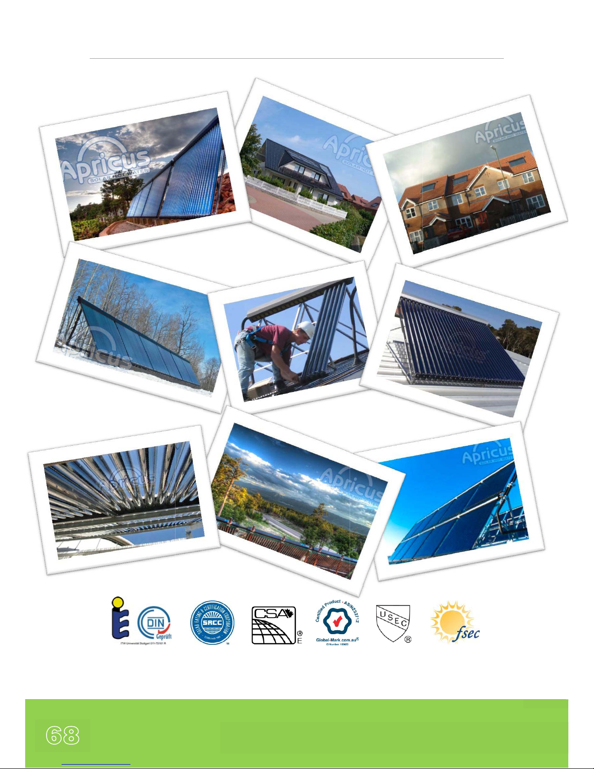
Apricus Installation Manual
68
CoolSky Ltd., 42 Milecross Road, Newtownards, BT23 4SR, Northern Ireland, U.K.
Copyright © 2012 CoolSky Ltd.
CoolSky Ltd. are Distributors for Apricus Solar Ltd. Products in the UK and Ireland
Apricus Solar Ltd. are a global supplier of Solar Thermal Collectors and associated components.
P00538A
 Loading...