

Coolpak PCA050, PCA100, PCA150 Operation Manual
PCA Series Air Cooled Portable Water Chiller
Operation Manual
Write Down Your Serial Numbers Here For Future Reference:
_________________________ _________________________
_________________________ _________________________
_________________________ _________________________

We are committed to a continuing program of product improvement.
Specifications, appearance, and dimensions described in this manual
are subject to change without notice.
Page | 2

Chapter 1: Safety
1-1 How to Use This Manual
Use this manual as a guide and reference for installing, operating, and maintaining your
equipment. The purpose is to assist you in applying efficient, proven techniques that enhance
equipment productivity.
This manual covers only light corrective maintenance. No other maintenance should be
undertaken without first contacting a service engineer.
The Functional Description section outlines models covered, standard features, and optional
features. Additional sections within the manual provide instructions for installation, preoperational procedures, operation, preventive maintenance, and corrective maintenance.
The Installation chapter includes required data for receiving, unpacking, inspecting, and setup
of the equipment. We can also provide the assistance of a factory-trained technician to help
train your operator(s) for a nominal charge. This section includes instructions, checks, and
adjustments that should be followed before commencing with operation of the equipment.
These instructions are intended to supplement standard shop procedures performed at shift,
daily, and weekly intervals.
The Operation chapter includes a description of electrical and mechanical controls, in addition
to information for operating the equipment safely and efficiently.
The Maintenance chapter is intended to serve as a source of detailed assembly and
disassembly instructions for those areas of the equipment requiring service. Preventive
maintenance sections are included to ensure that your equipment provides excellent, long
service.
The Troubleshooting chapter serves as a guide for identification of most common problems.
Potential problems are listed, along with possible causes and related solutions.
The Appendix contains technical specifications, drawings, schematics, and parts lists. A
spare parts list with part numbers specific to your machine is provided with your shipping
paperwork package. Refer to this section for a listing of spare parts for purchase. Have your
serial number and model number ready when ordering.
Safety Symbols Used in this Manual
The following safety alert symbols are used to alert you to potential personal injury hazards.
Obey all safety messages that follow these symbols to avoid possible injury or death.
DANGER indicates an imminently hazardous situation which, if not avoided, will
result in death or serious injury.
WARNING indicates a potentially hazardous situation or practice which, if not
avoided, could result in death or serious injury.
CAUTION indicates a potentially hazardous situation or practice which, if not
avoided, may result in minor or moderate injury or in property damage.
Page | 3

Table of Contents
1 General Information .................................................7
1-1 Introduction
1-2 Necessary Documents
1-3 Models Covered
1-4 Available Options
1-5 Uncrating Your New Chiller
1-6 In the Event of Shipping Damages
1-7 If the Shipment is Not Complete
1-8 If the Shipment is Incorrect
1-9 Returns
2 Chiller Installation ..................................................13
2-1 Electrical Connections
2-2 Process Water Connections
2-3 PCA Condenser Air Supply
2-4 Water Reservoir
2-5 Overhead Process Considerations
3 Sequence of Operation ..........................................17
3-1 Chilled Water Circuit
3-2 Refrigeration Circuit
3-3 High Pressure Cutout
3-4 Low Pressure Cutout
Page | 4

4 Startup Checklists ..................................................23
4-1 Introduction
4-2 PCA Pre-Start-up Checklist
4-3 PCA Start-up Checklist
4-4 PCA Water Circuit Pressure Drop Table
5 Microprocessor Control.........................................25
5-1 Introduction
5-2 Setting the Process Water Temperature
5-3 LED Indicators
5-4 Temperature Controller Keys
5-5 Auto-Tuning PCA Series Chillers
5-6 Optional Communications
6 Optional Graphic Panel..........................................30
6-1 Indicator Lights
6-2 Switches
7 Routine Maintenance .............................................32
7-1 Lubrication
7-2 Condenser Maintenance
Page | 5

Charts and Figures
Figure 1: PCA050 Process Pump Curves ................................................. .. .................................... 11
Figure 2: PCA100 Process Pump Curves ........................................................... ... .......................... 11
Figure 3: PCA150 Process Pump Curves ............................................................. ........................... 11
Figure 4: PCA Cast Iron Centrifugal Pump Curve 1/3 hp (0.249 kW)....................................... ....... 12
Figure 5: PCA Series Chiller Specifications....................................................... ..... .......................... 13
Figure 6: Ethylene Glycol Curve ....................................................................... .... ........................... 16
Figure 7: Overhead Piping .................................................................................. .... ......................... 17
Figure 8: PCA Component Identification ................................................................. ......................... 20
Figure 9: Piping Schematic - 1 Pump with Reservoir............................................. ..... ...................... 21
Figure 10: Piping Schematic - 1 Pump Without Reservoir....................................... ..... .................... 22
Figure 11: Piping Schematic - No Pump, No Reservoir.................................................. ..... ............. 23
Figure 12: Typical PCA Series E5CK Microprocessor Controller.............................. ....... ................ 27
Figure 13: Optional Graphic Panel .................................................................................. .... ............. 32
Figure 14: Typical PCA Subpanel ................................................................................... .... ............. 33
Figure 15: Typical PCA Wiring Schematic ................................................................... ..... ............... 34
Figure 16: PCA Wiring Schematic for Chillers with No Pump or Reservoir................. ....... .............. 35
Page | 6

General Information
1-1 Introduction
PCA Series Water Chillers are reliable, accurate, and easy-to-use air cooled chillers designed
for use with water/glycol. Standard range of operation is -1°C to 18°C for applications using
glycol and 7ºC to 18°C for water only applications. A crankcase pressure regulating valve
option is available for processes requiring a leaving water temperature of up to 24°C. PCA
models are available in 373 W (1/2 hp.), 746 W (1 hp.), and 1.1 kW (1-1/2 hp.) models and
have an internal 23 litre reservoir. All models are self contained, fully assembled, and shipped
ready to use.
A properly installed, operated, and maintained PCA Series Chiller will provide many years of
reliable operation. To get the most satisfaction from your new chiller, read and follow the
instructions in this manual.
1-2 Necessary Documents
The following documents are necessary for the operation, installation and maintenance of
PCA Series Chillers. Additional copies are available from Fleming Dynamics Pty Ltd.
Familiarize the appropriate personnel with these documents:
This manual.
The electrical schematic and connection diagram mounted inside the control enclosure.
Typical schematics for general reference are provided in Figure 15 and Figure 16 on
pages 34 and 35.
The operation and installation manuals for installed accessories and options.
The Customer Parts List included in the information packet.
1-3 Models Covered
This manual provides operation, installation, and maintenance instructions for PCA Series
Chillers.
Model numbers are on the serial tag. Please know the model number, serial number and
operating voltage of your chiller if you need to contact Fleming Dynamics Pty Ltd.
PCA Series Chiller models are designated by approximate compressor horsepower.
PCA050 chiller has a 373 W (1/2 hp.) compressor
PCA100 chiller has a. 746W (1 hp.) compressor
PCA150 chiller has a 1,118 W (1-1/2 hp.) compressor
Page | 7

1-4 Available Options
PCA Series Chillers are available with options that tailor the unit to your requirements.
Some are factory installed, some can be retrofitted in the field.
Some of these options are:
Special Pumps
Special pump options are available for greater pressure and flow rates. Bronze and stainless
steel wetted surface standard flow pumps ranging from 2.07 Bar to 4.14 Bar are available.
Reservoirs
PCA Series Chillers are available without a reservoir for processes that use their own
reservoir.
Power Cord
A 3 meter power cord is available to speed PCA installation.
Casters
Four 50mm swivel casters add mobility to the PCA unit.
CPR Valve
A crankcase pressure regulating (CPR) valve is available for leaving water temperatures up to
24°C.
1-5 Un-crating Your New Chiller
PCA Series Chillers are shipped mounted on a skid, enclosed in a plastic wrapper, and open
crated on all four sides and top.
Pry the crating away from the skid and remove. Use a pry bar to remove the blocks
securing the unit to the skid.
Lift the unit off the skid with a fork truck. Insert forks between skid and chiller from the
side until they protrude beyond the opposite side of the unit. The forks must be
equidistant from the centre line of the unit and the unit must be balanced on the forks.
Lift slowly and only high enough to clear the skid. Use a pry bar if necessary to
remove the skid from the unit.
Lower slowly. The unit will land on its feet or casters and can be moved into position.
Page | 8

1-6 In the Event of Shipping Damages
IMPORTANT!
According to the contract terms and conditions of the Carrier, the responsibility of the
shipper ends at the time and place of shipment.
The Carrier then assumes full responsibility of the shipment.
Notify the transportation company's local agent.
Hold the damaged goods and packing material for the examining agent's inspection.
Do not return any goods to Fleming Dynamics before the transportation company
inspection and authorization.
File a claim against the transportation company. Substantiate the claim by referring to
the agent's report. A certified copy of our invoice is available upon request. The
original Bill of Lading is attached to our original invoice. If the shipment was
prepaid, write us for a receipted transportation bill.
Advise Fleming Dynamics regarding your wish for replacement.
1-7 If the Shipment is Not Complete
Check the packing list. The apparent shortage may be intentional. Back-ordered items are
noted on the packing list. You should have:
PCA Series Chiller
Bill of Lading
Packing List
Operating and Installation Packet
Re-inspect the container and packing material to see if smaller items have been missed
during unpacking. Determine that the item was not taken from the area before the shipment
was checked in. Notify Fleming Dynamics immediately of the shortage.
1-8 If the Shipment is Incorrect
If the shipment is not what you ordered, contact Fleming Dynamics immediately.
Include the order number and item.
Hold the items until shipping instructions are received.
Page | 9

1-9 Returns
IMPORTANT!
Do not return any damaged or incorrect items until you receive shipping instructions from
Fleming Dynamics.
Page | 10

Page | 11

Page | 12
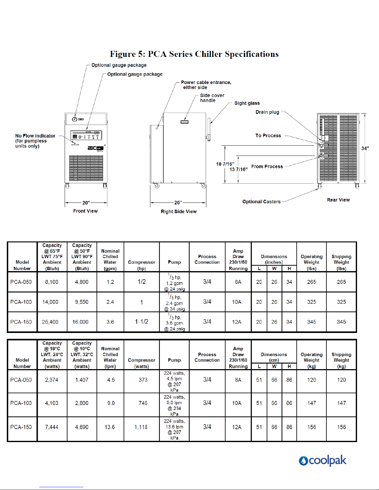
(¾” BSP)
(¾” BSP)
(¾” BSP)
(inches BSP)
(inches BSP)
Page | 13
 Loading...