

Page 1
PCA Series Air Cooled Portable Water Chiller
Operation Manual
Write Down Your Serial Numbers Here For Future Reference:
_________________________ _________________________
_________________________ _________________________
_________________________ _________________________
Page 2

We are committed to a continuing program of product improvement.
Specifications, appearance, and dimensions described in this manual
are subject to change without notice.
Page | 2
Page 3

Chapter 1: Safety
1-1 How to Use This Manual
Use this manual as a guide and reference for installing, operating, and maintaining your
equipment. The purpose is to assist you in applying efficient, proven techniques that enhance
equipment productivity.
This manual covers only light corrective maintenance. No other maintenance should be
undertaken without first contacting a service engineer.
The Functional Description section outlines models covered, standard features, and optional
features. Additional sections within the manual provide instructions for installation, preoperational procedures, operation, preventive maintenance, and corrective maintenance.
The Installation chapter includes required data for receiving, unpacking, inspecting, and setup
of the equipment. We can also provide the assistance of a factory-trained technician to help
train your operator(s) for a nominal charge. This section includes instructions, checks, and
adjustments that should be followed before commencing with operation of the equipment.
These instructions are intended to supplement standard shop procedures performed at shift,
daily, and weekly intervals.
The Operation chapter includes a description of electrical and mechanical controls, in addition
to information for operating the equipment safely and efficiently.
The Maintenance chapter is intended to serve as a source of detailed assembly and
disassembly instructions for those areas of the equipment requiring service. Preventive
maintenance sections are included to ensure that your equipment provides excellent, long
service.
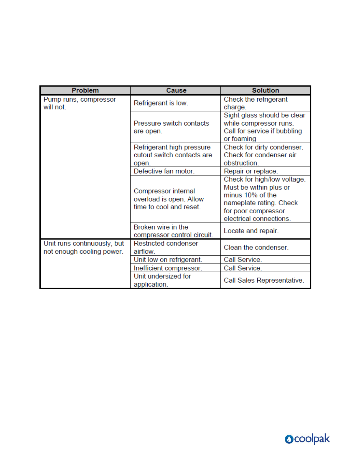
The Troubleshooting chapter serves as a guide for identification of most common problems.
Potential problems are listed, along with possible causes and related solutions.
The Appendix contains technical specifications, drawings, schematics, and parts lists. A
spare parts list with part numbers specific to your machine is provided with your shipping
paperwork package. Refer to this section for a listing of spare parts for purchase. Have your
serial number and model number ready when ordering.
Safety Symbols Used in this Manual
The following safety alert symbols are used to alert you to potential personal injury hazards.
Obey all safety messages that follow these symbols to avoid possible injury or death.
DANGER indicates an imminently hazardous situation which, if not avoided, will
result in death or serious injury.
WARNING indicates a potentially hazardous situation or practice which, if not
avoided, could result in death or serious injury.
CAUTION indicates a potentially hazardous situation or practice which, if not
avoided, may result in minor or moderate injury or in property damage.
Page | 3
Page 4

Table of Contents
1 General Information .................................................7
1-1 Introduction
1-2 Necessary Documents
1-3 Models Covered
1-4 Available Options
1-5 Uncrating Your New Chiller
1-6 In the Event of Shipping Damages
1-7 If the Shipment is Not Complete
1-8 If the Shipment is Incorrect
1-9 Returns
2 Chiller Installation ..................................................13
2-1 Electrical Connections
2-2 Process Water Connections
2-3 PCA Condenser Air Supply
2-4 Water Reservoir
2-5 Overhead Process Considerations
3 Sequence of Operation ..........................................17
3-1 Chilled Water Circuit
3-2 Refrigeration Circuit
3-3 High Pressure Cutout
3-4 Low Pressure Cutout
Page | 4
Page 5

4 Startup Checklists ..................................................23
4-1 Introduction
4-2 PCA Pre-Start-up Checklist
4-3 PCA Start-up Checklist
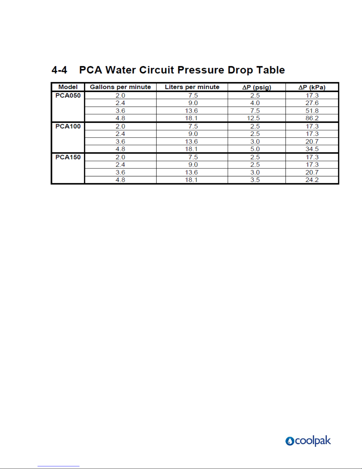
4-4 PCA Water Circuit Pressure Drop Table
5 Microprocessor Control.........................................25
5-1 Introduction
5-2 Setting the Process Water Temperature
5-3 LED Indicators
5-4 Temperature Controller Keys
5-5 Auto-Tuning PCA Series Chillers
5-6 Optional Communications
6 Optional Graphic Panel..........................................30
6-1 Indicator Lights
6-2 Switches
7 Routine Maintenance .............................................32
7-1 Lubrication
7-2 Condenser Maintenance
Page | 5
Page 6

Charts and Figures
Figure 1: PCA050 Process Pump Curves ................................................. .. .................................... 11
Figure 2: PCA100 Process Pump Curves ........................................................... ... .......................... 11
Figure 3: PCA150 Process Pump Curves ............................................................. ........................... 11
Figure 4: PCA Cast Iron Centrifugal Pump Curve 1/3 hp (0.249 kW)....................................... ....... 12
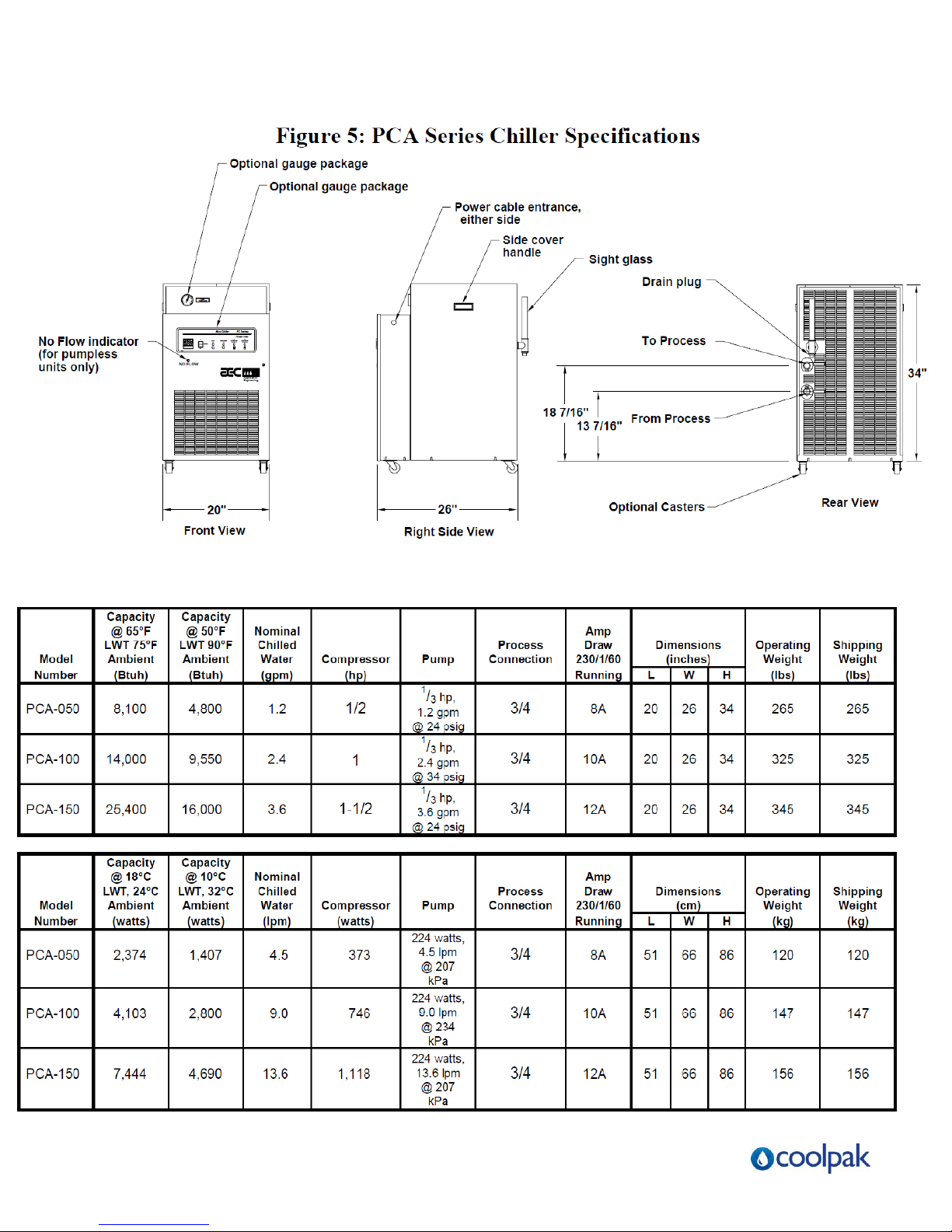
Figure 5: PCA Series Chiller Specifications....................................................... ..... .......................... 13
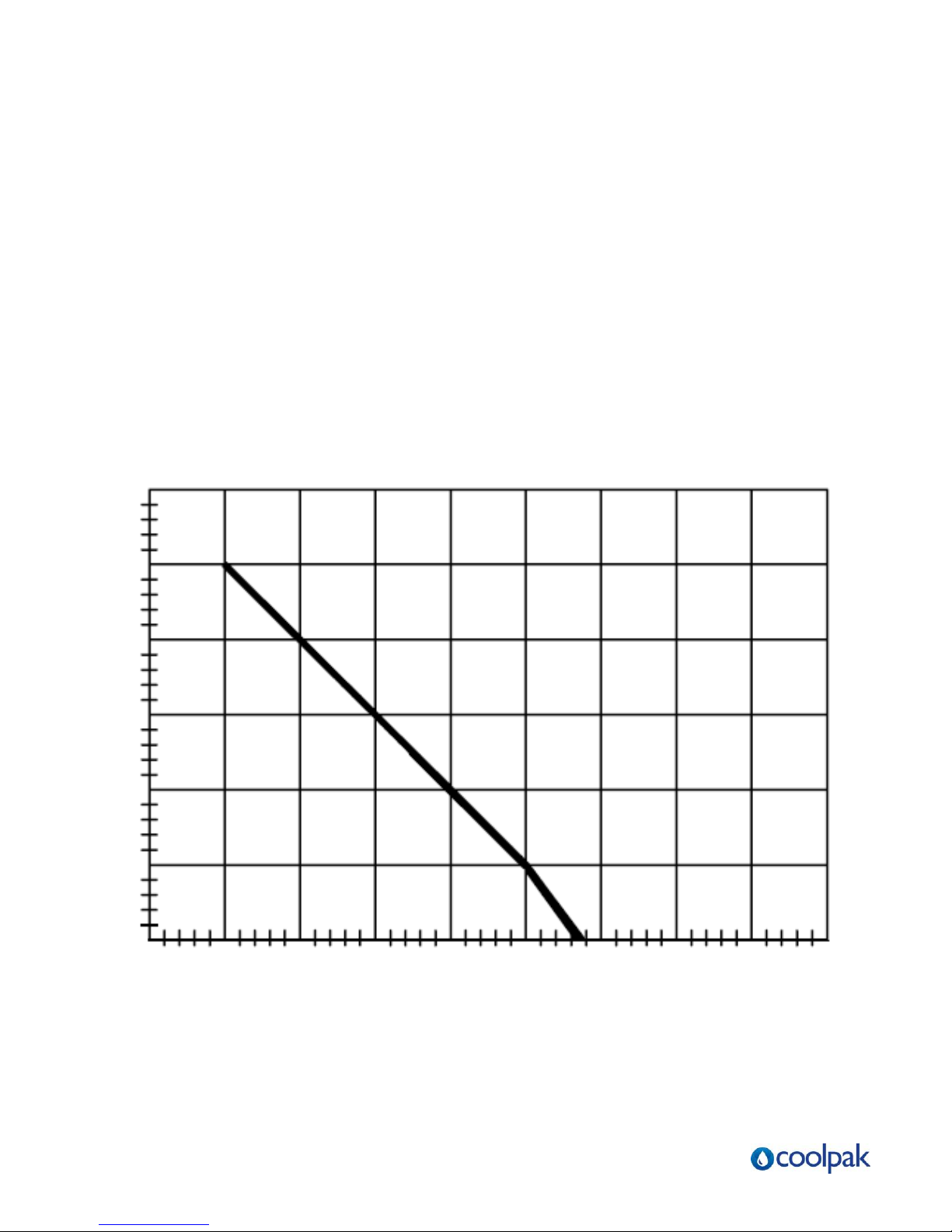
Figure 6: Ethylene Glycol Curve ....................................................................... .... ........................... 16
Figure 7: Overhead Piping .................................................................................. .... ......................... 17
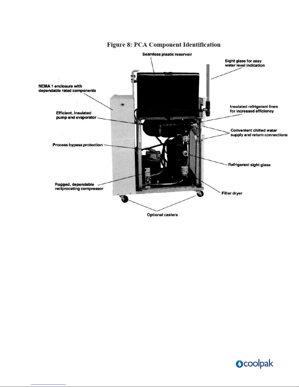
Figure 8: PCA Component Identification ................................................................. ......................... 20
Figure 9: Piping Schematic - 1 Pump with Reservoir............................................. ..... ...................... 21
Figure 10: Piping Schematic - 1 Pump Without Reservoir....................................... ..... .................... 22
Figure 11: Piping Schematic - No Pump, No Reservoir.................................................. ..... ............. 23
Figure 12: Typical PCA Series E5CK Microprocessor Controller.............................. ....... ................ 27
Figure 13: Optional Graphic Panel .................................................................................. .... ............. 32
Figure 14: Typical PCA Subpanel ................................................................................... .... ............. 33
Figure 15: Typical PCA Wiring Schematic ................................................................... ..... ............... 34
Figure 16: PCA Wiring Schematic for Chillers with No Pump or Reservoir................. ....... .............. 35
Page | 6
Page 7

General Information
1-1 Introduction
PCA Series Water Chillers are reliable, accurate, and easy-to-use air cooled chillers designed
for use with water/glycol. Standard range of operation is -1°C to 18°C for applications using
glycol and 7ºC to 18°C for water only applications. A crankcase pressure regulating valve
option is available for processes requiring a leaving water temperature of up to 24°C. PCA
models are available in 373 W (1/2 hp.), 746 W (1 hp.), and 1.1 kW (1-1/2 hp.) models and
have an internal 23 litre reservoir. All models are self contained, fully assembled, and shipped
ready to use.
A properly installed, operated, and maintained PCA Series Chiller will provide many years of
reliable operation. To get the most satisfaction from your new chiller, read and follow the
instructions in this manual.
1-2 Necessary Documents
The following documents are necessary for the operation, installation and maintenance of
PCA Series Chillers. Additional copies are available from Fleming Dynamics Pty Ltd.
Familiarize the appropriate personnel with these documents:
This manual.
The electrical schematic and connection diagram mounted inside the control enclosure.
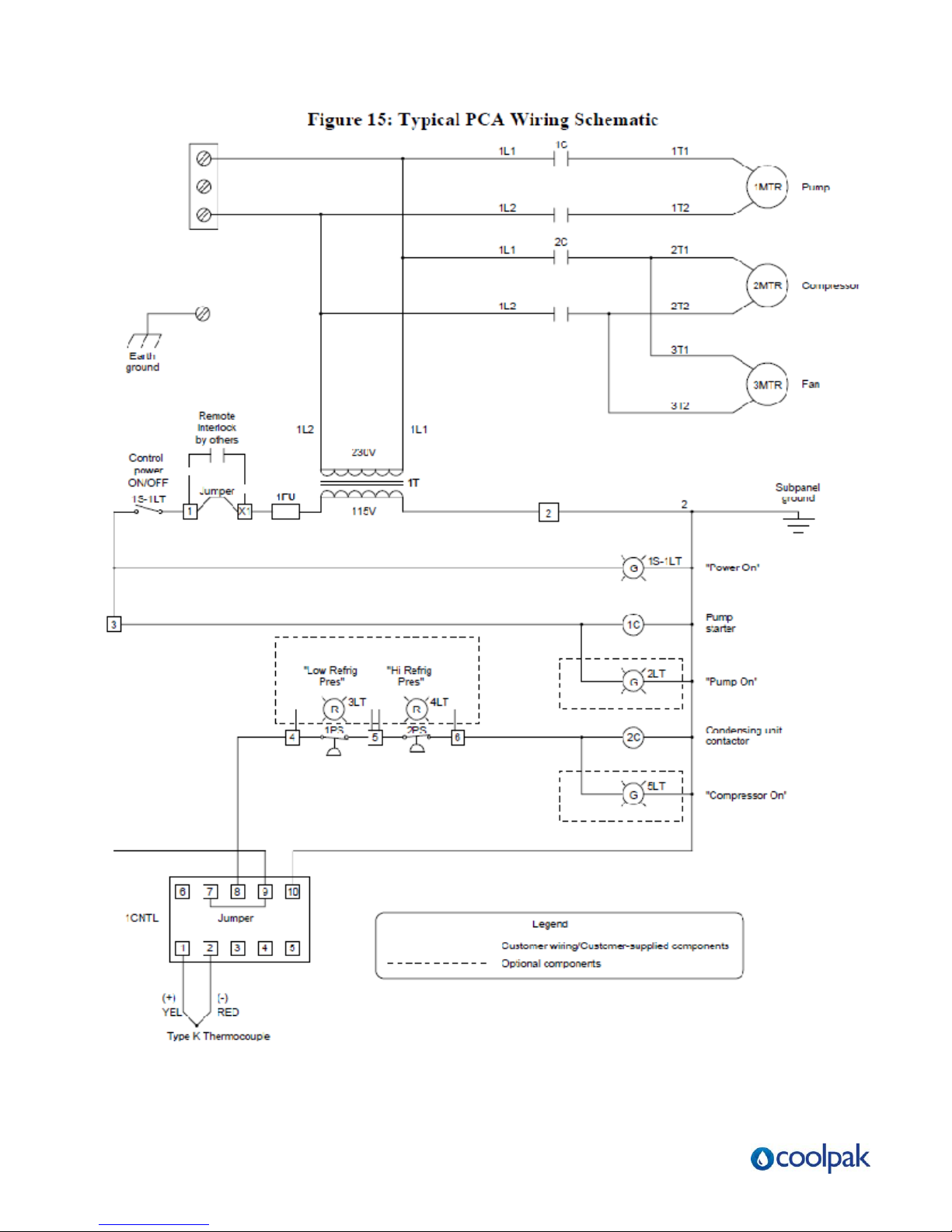
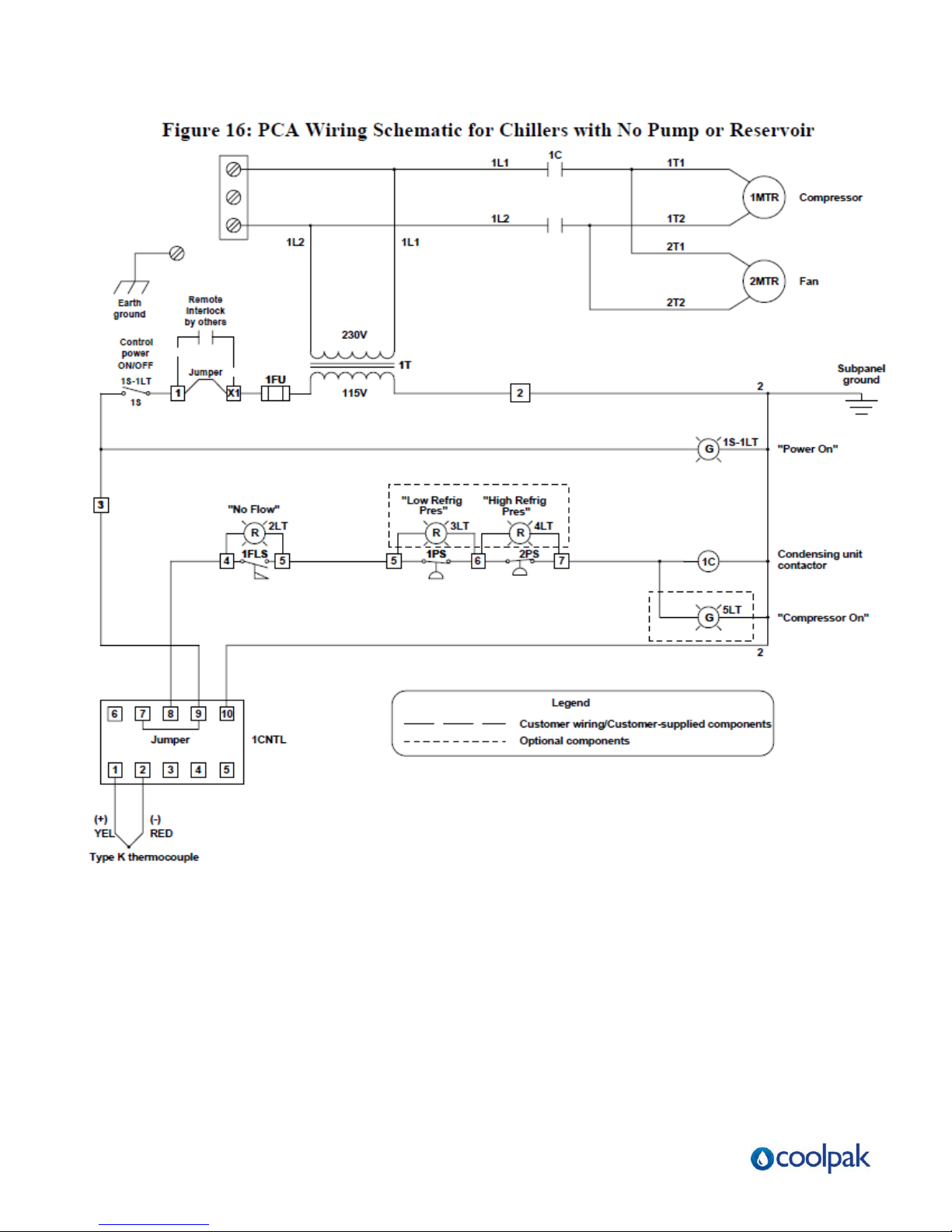
Typical schematics for general reference are provided in Figure 15 and Figure 16 on
pages 34 and 35.
The operation and installation manuals for installed accessories and options.
The Customer Parts List included in the information packet.
1-3 Models Covered
This manual provides operation, installation, and maintenance instructions for PCA Series
Chillers.
Model numbers are on the serial tag. Please know the model number, serial number and
operating voltage of your chiller if you need to contact Fleming Dynamics Pty Ltd.
PCA Series Chiller models are designated by approximate compressor horsepower.
PCA050 chiller has a 373 W (1/2 hp.) compressor
PCA100 chiller has a. 746W (1 hp.) compressor
PCA150 chiller has a 1,118 W (1-1/2 hp.) compressor
Page | 7
Page 8

1-4 Available Options
PCA Series Chillers are available with options that tailor the unit to your requirements.
Some are factory installed, some can be retrofitted in the field.
Some of these options are:
Special Pumps
Special pump options are available for greater pressure and flow rates. Bronze and stainless
steel wetted surface standard flow pumps ranging from 2.07 Bar to 4.14 Bar are available.
Reservoirs
PCA Series Chillers are available without a reservoir for processes that use their own
reservoir.
Power Cord
A 3 meter power cord is available to speed PCA installation.
Casters
Four 50mm swivel casters add mobility to the PCA unit.
CPR Valve
A crankcase pressure regulating (CPR) valve is available for leaving water temperatures up to
24°C.
1-5 Un-crating Your New Chiller
PCA Series Chillers are shipped mounted on a skid, enclosed in a plastic wrapper, and open
crated on all four sides and top.
Pry the crating away from the skid and remove. Use a pry bar to remove the blocks
securing the unit to the skid.
Lift the unit off the skid with a fork truck. Insert forks between skid and chiller from the
side until they protrude beyond the opposite side of the unit. The forks must be
equidistant from the centre line of the unit and the unit must be balanced on the forks.
Lift slowly and only high enough to clear the skid. Use a pry bar if necessary to
remove the skid from the unit.
Lower slowly. The unit will land on its feet or casters and can be moved into position.
Page | 8
Page 9

1-6 In the Event of Shipping Damages
IMPORTANT!
According to the contract terms and conditions of the Carrier, the responsibility of the
shipper ends at the time and place of shipment.
The Carrier then assumes full responsibility of the shipment.
Notify the transportation company's local agent.
Hold the damaged goods and packing material for the examining agent's inspection.
Do not return any goods to Fleming Dynamics before the transportation company
inspection and authorization.
File a claim against the transportation company. Substantiate the claim by referring to
the agent's report. A certified copy of our invoice is available upon request. The
original Bill of Lading is attached to our original invoice. If the shipment was
prepaid, write us for a receipted transportation bill.
Advise Fleming Dynamics regarding your wish for replacement.
1-7 If the Shipment is Not Complete
Check the packing list. The apparent shortage may be intentional. Back-ordered items are
noted on the packing list. You should have:
PCA Series Chiller
Bill of Lading
Packing List
Operating and Installation Packet
Re-inspect the container and packing material to see if smaller items have been missed
during unpacking. Determine that the item was not taken from the area before the shipment
was checked in. Notify Fleming Dynamics immediately of the shortage.
1-8 If the Shipment is Incorrect
If the shipment is not what you ordered, contact Fleming Dynamics immediately.
Include the order number and item.
Hold the items until shipping instructions are received.
Page | 9
Page 10

1-9 Returns
IMPORTANT!
Do not return any damaged or incorrect items until you receive shipping instructions from
Fleming Dynamics.
Page | 10
Page 11

Page | 11
Page 12

Page | 12
Page 13
(¾” BSP)
(¾” BSP)
(¾” BSP)
(inches BSP)
(inches BSP)
Page | 13
Page 14

2 Chiller Installation
2-1 Electrical Connections
Check serial tag voltage and amperage requirements and make sure your electrical
service conforms. See Figure 5 on page 13 for total running amps.
Bring properly sized power leads and ground from a fused disconnect (installed by your
electrician) to the main power terminal in the chiller's electrical enclosure.
Electrical connections must comply with all applicable electrical codes
The chiller must be grounded in accordance with NEC Article 250
Voltage must be within 10% of the chiller's nameplate rating.
2-2 Process Water Connections
All external chilled water connections to the process must be of adequate size.
See Figure 7 on page See 17 for sizing recommendations.
The largest possible openings and passages should be provided for the flow of chilled water
through platens, dies, moulds or other pieces of equipment.
IMPORTANT!
Keep any pressure drop in external process piping to an absolute minimum for optimum unit
operation.
To Process
Connect the TO PROCESS chilled water supply outlet to the process being cooled.
From Process
Connect the FROM PROCESS chilled water return inlet to the return from the process
back into the chiller for cooling and recirculation.
Fleming Dynamics recommends a strainer on the FROM PROCESS return line.
Page | 14
Page 15
Ambient Temperature Range
Minimum Temperature
Maximum Temperature
Operation
18°C
38°C
Storage
4°C
49°C
Process Water Bypass
All PCA chillers have an internal bypass device (patent pending). If the process flow becomes
blocked during chiller operation, this component allows water to flow through the chiller. This
protects the chiller from freeze-up, excessive pressures, and pump damage, and allows other safety
features to remain effective.
2-3 PCA Condenser Air Supply
PCA chillers use the surrounding air to cool the condenser.
Condenser air entering the PCA unit should be at least 65°F (18°C). Operation with air below
65°F (18°C) can cause the low pressure cut-out to shut down the chiller due to the low
refrigerant pressure.
Install the chiller in an area where there is free passage of air for condensing.
Provide 18" (46 cm) or more clearance for the chiller's air intake.
Make provisions to exhaust the heated air discharged from the chiller.
Do not put the PCA unit where steam, hot air or fume exhausts will be drawn into the
condenser.
Air-cooled condensers must be cleaned frequently. Neglect reduces capacity, increases
operating costs, and leads to possible chiller failure. See Chapter 7 on Page 29 for cleaning
instructions.
Normal condensing pressure with 95°F (35°C) air is approximately 1.241Bar for the PCA050
and PCA100; 1.897 Bar for the PCA150.
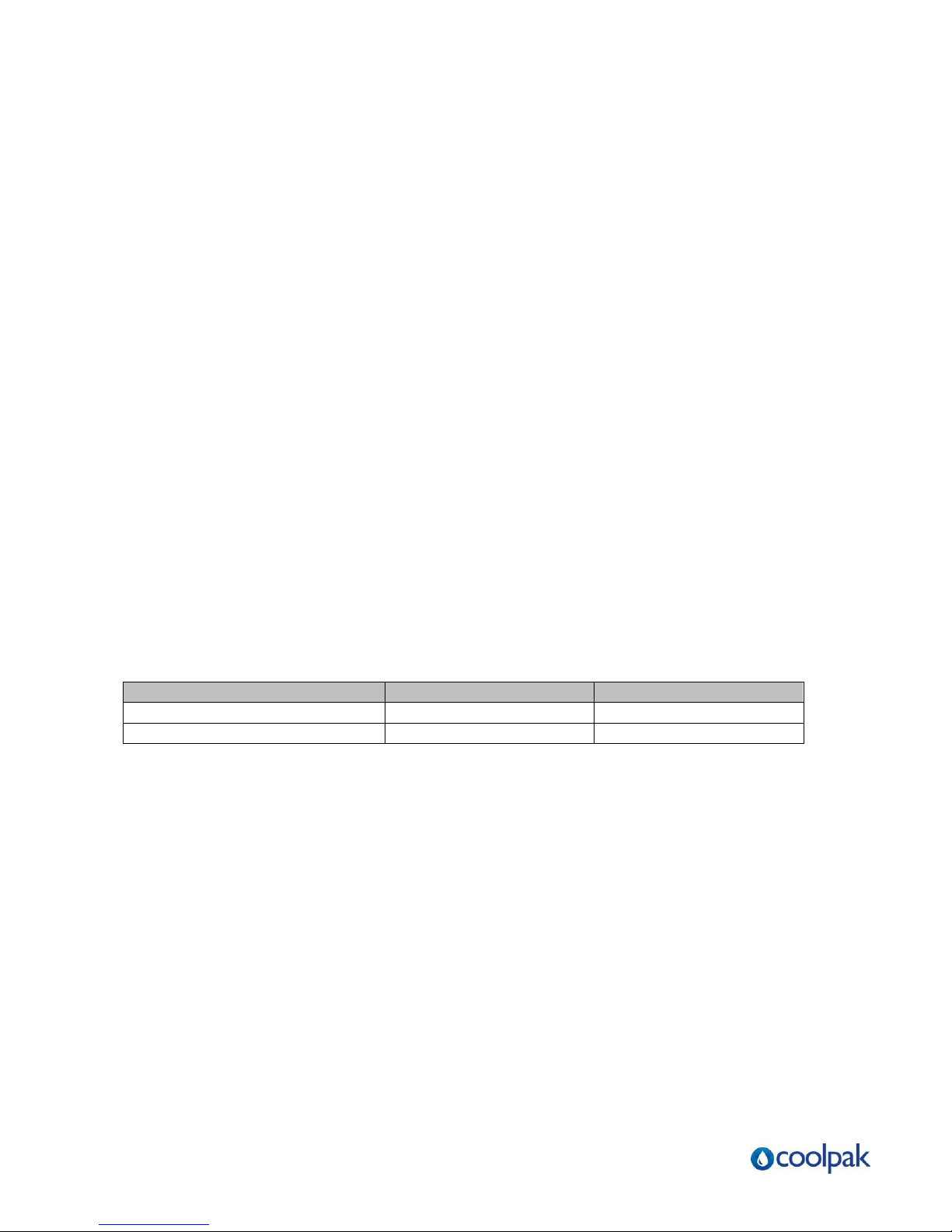
PCA Ambient Temperature Ranges
2-4 Water Reservoir
During start-up and when additional solution is required, see Figure 6 on page 16 for the
recommended ethylene glycol/water solution. This chart shows the proportions needed to provide
freeze protection to 7°C below the desired process set point.
Add a pre-mixed solution to provide freeze protection to a temperature 7°C below the normal
operating temperature of the chiller.
Use industrial quality (not automotive) ethylene glycol.
Page | 15
Page 16
Ethylene Glycol Required
For Evaporator Freeze Protection
Figure 6: Ethylene Glycol Curve
30%
Ethylene
Glycol
20%
Percent
By
Volume
10%
0%
-3.8
o
1.6o 7.2o 12.7o 18.3o
Chilled Water
A corrosion inhibitor suitable for the materials in the system should be added to the
glycol/water solution.
If straight water use is desired, contact Fleming Dynamics Pty Ltd.
The 23 litre reservoir is not designed to withstand water pressure above
34 kPa.
The fill opening and vent line must be vented to the atmosphere for proper operation.
Page | 16
Normal Operating Range between -1.1 oC – 21.1oC
Operating Temperature oC
(Set Point)
Page 17
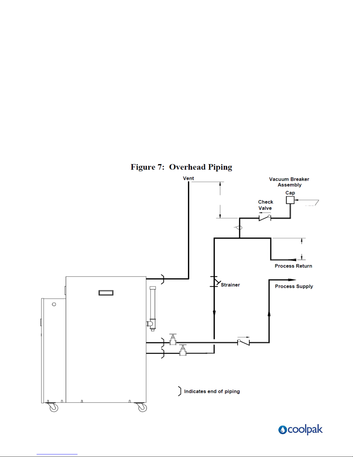
The reservoir vent & fill line
must remain open to the atmosphere.
300mm
Add check valve
150mm
6.35mm
3.18mm
Hole
2-5 Overhead Process Considerations
If your application has chilled water or process piping above the reservoir fill and vent level,
install a standpipe to a point 30 cm above the highest point in the system.
In applications where the process or its piping is 4.6 m or more above the reservoir, you
must take steps to prevent over-pressurization of the reservoir. This
condition can occur on system shutdown when the water in the system drains into the
reservoir.
To prevent this, install a check valve in the unit TO PROCESS line and a vacuum breaker at
the high point of the return FROM PROCESS line. See Figure 7 below for more information.
Note: The reserve capacity of the reservoir can hold a volume equal to 6.1 m
of 25mm pipe.
to be piped 304.8mm above the highest
point of the system. The vent line
Page | 17
if system piping
extends 4.6M
above reservoir
Page 18
IMPORTANT!
Such damage is not covered by the Fleming Dynamics warranty.
3 Sequence of Operation
• The PCA unit has a leaving water temperature range of -1°C to 18°C. Do not
• When operating the PCA unit between -1°C and 5°C, you must
3-1 Chilled Water Circuit
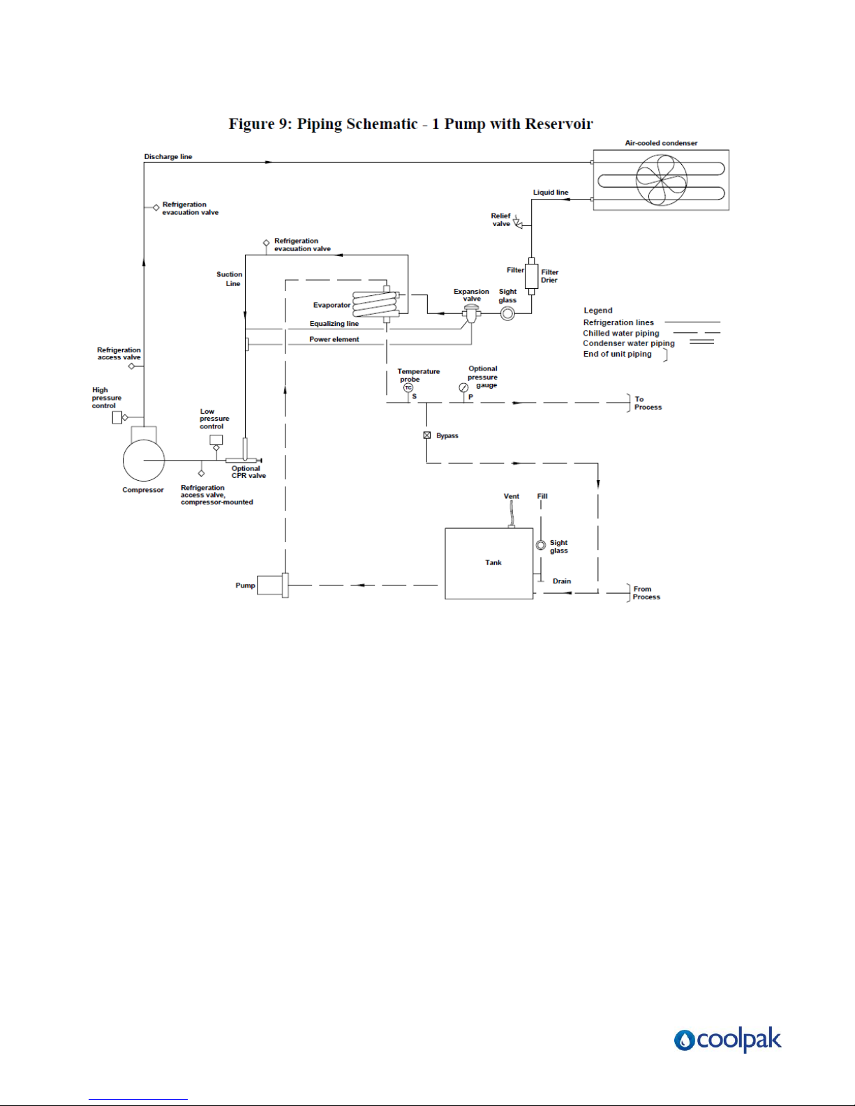
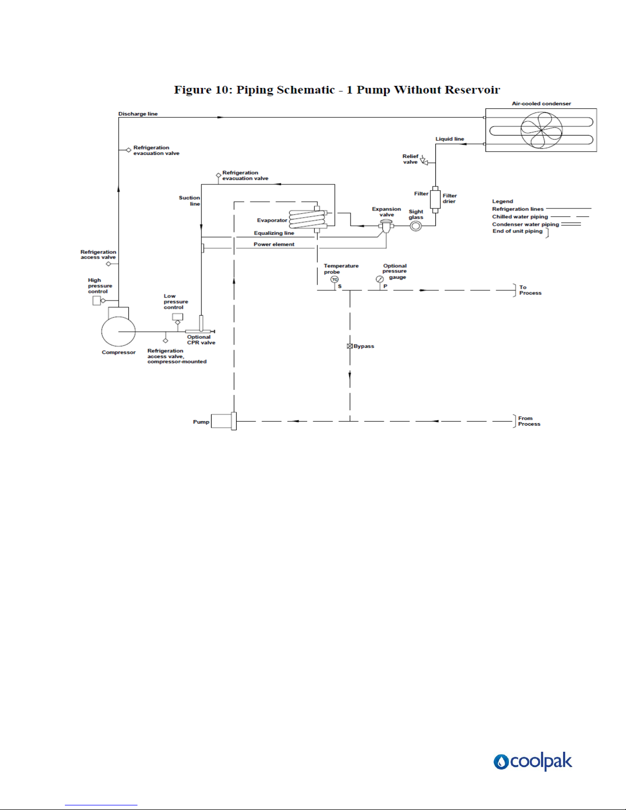
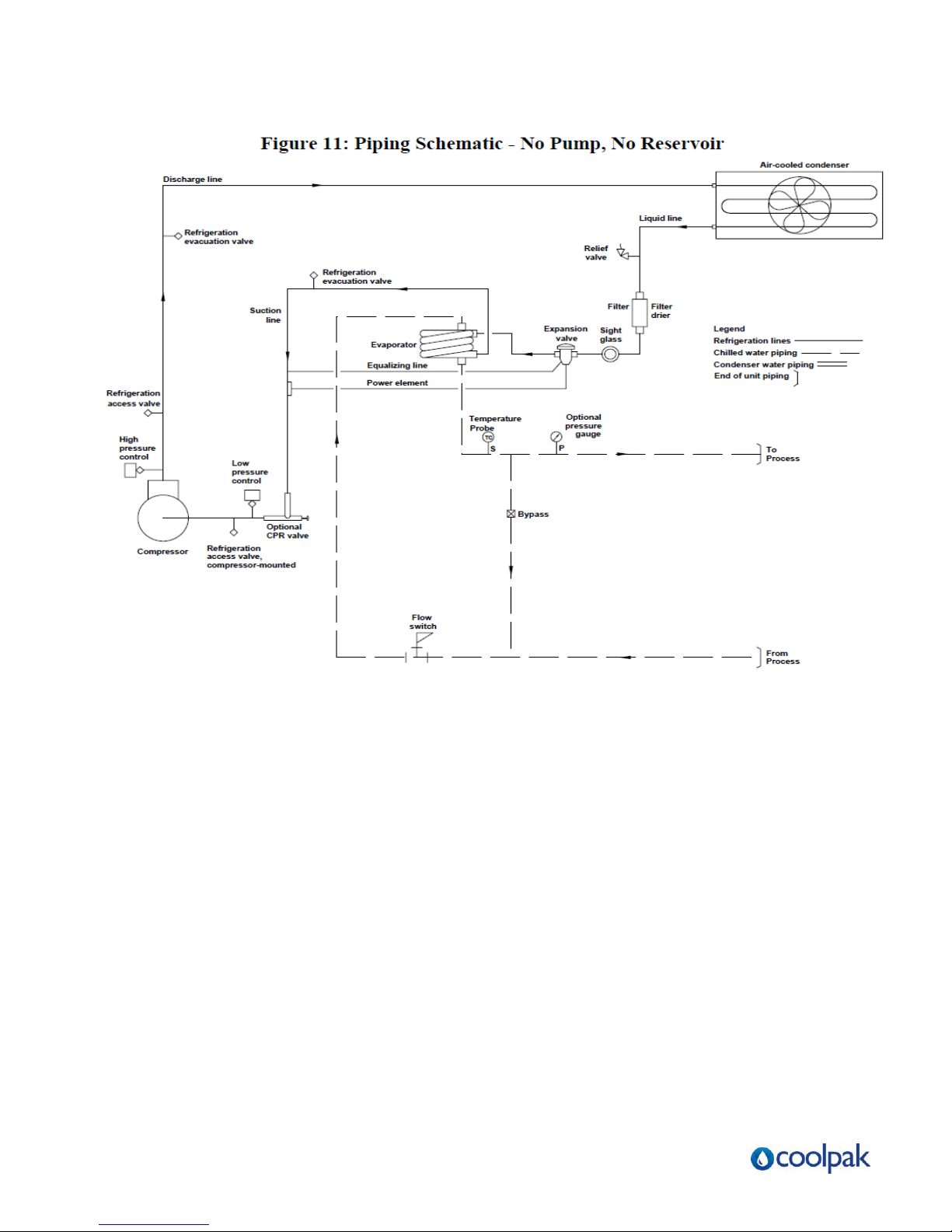
Figure 9, Figure 10, and Figure 11
Process cooling water supply and return connections are made at the pipe stubs at the rear of the
chiller.
Warm water returns from the process and enters the reservoir tank.
The process water is pumped through the evaporator where it is cooled.
The coolant flows to the process and returns to repeat the cycle.
A chilled water bypass assembly (patent pending) between the supply and return lines guarantees a
A flow switch in units without pumps will prevent the compressor from running without adequate
attempt to run the PCA unit outside this temperature range or
damage to the unit may occur.
use a solution of 75% water and 25% industrial-grade ethylene glycol with a
suitable corrosion inhibitor to protect the PCA unit from freeze-up.
See Figure 6 on page 16 for more information.
constant flow through the evaporator during intermittent low or no-flow conditions.
flow through the evaporator
3-2 Refrigeration Circuit
Liquid refrigerant from the condenser passes through a filter/dryer which removes moisture and other
contaminants.
The refrigerant then passes through the thermal expansion valve which allows the refrigerant to
expand and cool the inside of the heat exchanger. The refrigerant flows through the suction line to the
compressor.
The refrigerant gives up its heat as it re-condenses to a liquid in the condenser and the cycle starts
over again.
Page | 18
Page 19
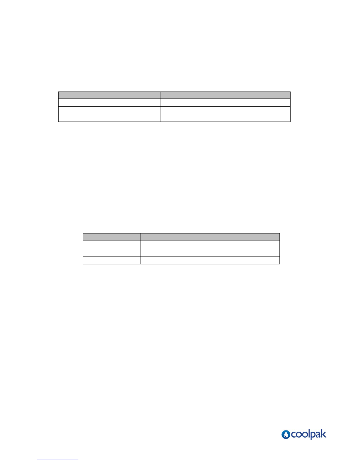
Model
Cuts out if condensing pressure exceeds:
PCA050
1.897 Bar
PCA100
1.897 Bar
PCA150
2.759 Bar
Model
Cuts out if suction pressure falls below:
PCA050
1.03 Bar
PCA100
1.03 Bar
PCA150
2.41Bar
3-3 High Pressure Cutout
The high pressure cutout is an electro-mechanical safety feature that opens the control
circuit if the system condensing pressure exceeds a safe level. The chiller will
automatically restart when the pressure drops back to an acceptable level.
IMPORTANT!
Call Fleming Dynamics to arrange a service technician to analyse the problem if high
pressure recurs.
3-4 Low Pressure Cut-out
The low pressure cut-out is an electro-mechanical safety feature that prevents compressor
suction pressure from dropping below a pre-set point.
It is factory set to open the control circuit when pressure drops below a safe level. The chiller
will automatically restart when the suction pressure reaches an acceptable level.
3-5 Remote Start/Stop Interlock
A contact is provided to allow interlocking of the PCA Series Chiller with process controls. To
use this feature, remove the jumper between Terminals X1 and 1 on Terminal Block 1.
Supply a switch or dry contact interlock connected in series between these two terminals.
See Figure 15 and Figure 16 on pages 34 and 35 for more information.
Page | 19
Page 20
Page | 20
Page 21
Page | 21
Page 22
Page | 22
Page 23
Page | 23
Page 24

4 Startup Checklist
4-1 Introduction
Follow the check lists below for the startup of your new chiller. These lists assume the
installation information elsewhere in this manual has been read and followed. New
chillers should be started up and checked by a qualified refrigeration service technician.
4-2 PCA Pre Start-up Checklist
1. Check the shipping papers against the serial tag to be sure chiller size, type and
voltage is correct for the process that will be controlled.
2. Check the transformer primary voltage connections to be sure they are
configured for the electrical power you are using. The voltage at the main power
connection must read within +/-10% of the voltage listed on the serial tag.
Electrical connections must conform to all applicable codes.
3. The chilled water TO PROCESS and FROM PROCESS connections should be completed.
4. Be sure the reservoir tank and chilled water circuit piping are filled with water.
5. The air-cooled condenser should have an adequate supply of air for proper operation.
6. Connect main power to the chiller and run the chiller just long enough to see if the pump is
generating normal pressure.
7. Check your work and proceed to the PCA Startup Checklist section below.
4-3 PCA Start-up Checklist
1. Turn ON the chiller. The PCA chiller should continue to run until the switch is turned OFF.
2. Put the PCA chiller under a process load.
3. Set the microprocessor control to the desired process temperature setpoint using the
, and buttons. See Chapter Five on Page 25 for more
information.
4. Check the pump amp draw and pump pressure. The amp draw reading must be within the
running load and service factor amps.
5. Operate the chiller, looking for leaks and listening for unusual noises or vibrations that could
indicate improper operation.
Page | 24
Page 25
Page | 25
Page 26
PCA Control Operation Range
Standard models
-1ºC to 18ºC
5 Microprocessor Control
5-1 Introduction
Standard PCA Series chillers use a microprocessor-based PID controller. The controller
is a modular, self-contained unit that can slide from its mounting housing. It is factory
set and adjusted; no field adjustment to the internal controls is necessary.
5-2 Setting the Process Water Temperature
To change the process water temperature set point:
• Press the Up Arrow button to raise the set point.
• Press the Down Arrow button to lower the set point.
5-3 LED Indicators
PV or Process Value Numeric LED
During normal operation, the large red PV LED on the controller displays the actual
process temperature at the To Process thermocouple. It also lists parameter symbols
during setup and error messages if an error occurs.
SV or Set Value Numeric LED
During normal operation, the green SV LED on the controller displays the process set
point you want the chiller to maintain. It also displays parameter and pre-set function
values during setup.
OUT1 LED
The orange OUT1 LED lights when the control output energizes the hot-gas bypass
solenoid valve.
Page | 26
Page 27
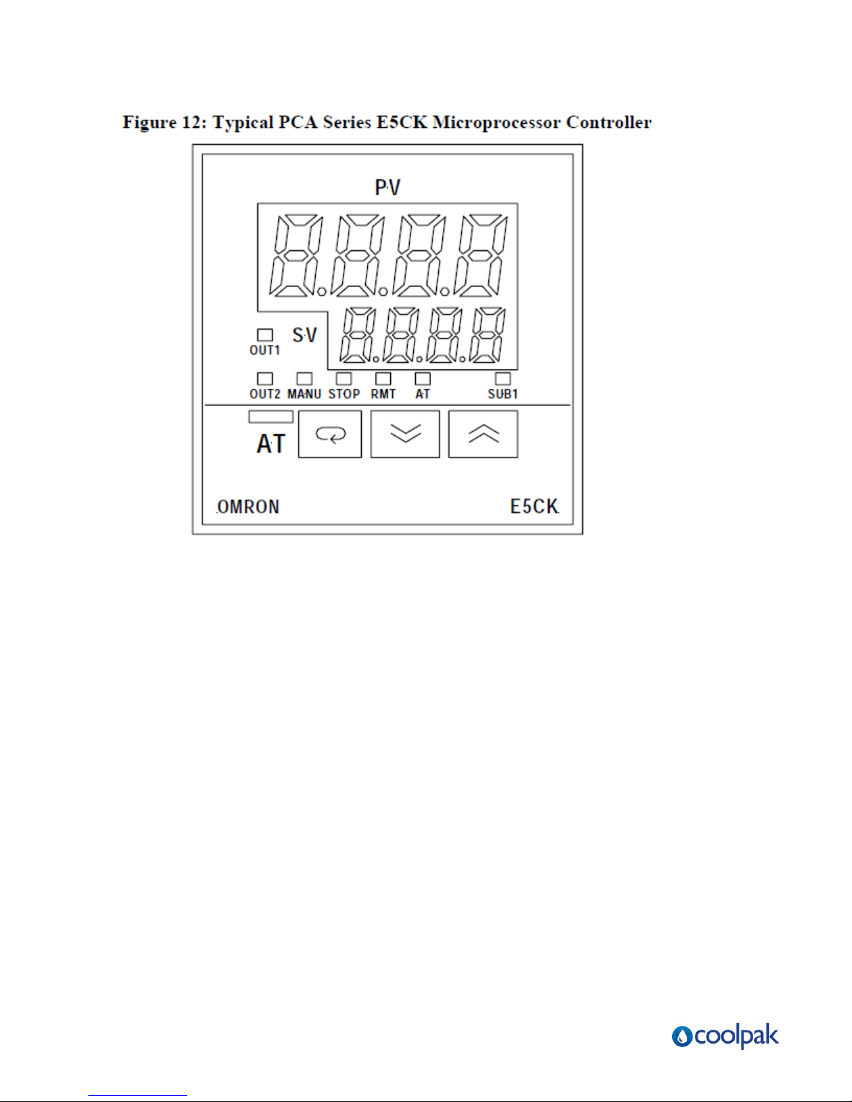
OUT2 LED
The orange OUT2 energizes whenever the process temperature is two degrees (2°F/ºC)
or more above the To Process set point. The compressor then comes on and runs until
the temperature at the To Process thermocouple is two degrees (2°F/ºC) below the set
point.
This +2°F/ºC control set point is factory-set for proper compressor operation. Changing
it is not recommended without consulting the Fleming Dynamics Service Department.
MANU LED
The orange MANU LED does not light because it is not used.
STOP LED
The orange STOP LED does not light because it is not used.
Page | 27
Page 28

RMT LED
The orange RMT LED is lit during remote operation.
AT LED
The orange AT LED flashes during auto-tuning.
SUB1 LED
The orange SUB1 LED energizes whenever the process temperature is two degrees
(2°F/ºC) or more below the To Process set point. The compressor then shuts down by
means of a latching circuit, and does not run again until the temperature at the To Process
thermocouple is two degrees (2°F/ºC) above the set point.
This +2°F/ºC control set point is factory-set for proper compressor operation.
Changing it is not recommended without consulting the Fleming Service Department.
5-4 Temperature Controller Keys
AT AT Key
Press and hold the AT AT key for two seconds to initiate or stop the auto-tune
function.
Display Key
The functions of the Display key change, based on how long you press it. Press
the Display key for less than one (1) second to scroll through parameters within the mode.
Press the Display key for at least one (1) second or more to display the menu; this function
also lets you select the mode you need to adjust.
Page | 28
Page 29

Important!
Factory default settings are: P = .3, I = 7, and D = 1
Important!
Do not change any of the control settings without consulting
the Fleming Dynamics Service Department.
The Fleming Dynamics Pty Ltd warranty does not cover chiller failures
from tampering with controller settings!
Down Key
Each press of the Down Arrow key decrements or reduces the values or
settings on the SV display.
Up Key
Each press of the Up Arrow key increments or advances the values or
settings on the SV display.
5-5 Auto-Tuning PCA Series Chillers
The Auto-Tune function lets you fine-tune the control PID to process requirements. Activate
the Auto-Tune function whenever the process under control changes. Don't be alarmed by
control
response. It may take the process temperature above and below the set points as many as
three (3) times. It will then level off and control to the process set point. Auto tuning can
take up to 45 minutes, and is best done before any product is being run.
To auto-tune the controller:
Press and hold down the AT AT key for several seconds until the AT indicator flashes.
The AT LED flashes to indicate that the control is tuning itself.When the AT LED light stops
flashing, the controller is tuned and ready for operation.
Page | 29
Page 30

5-6 Optional Communications
Standard Omron Protocol
The communications function allows you to monitor and set E5CK parameters by a
program prepared and running on a host computer connected to the E5CK controller.
When using the communications function, you must add on the unit for RS-232C or RS485 communications. The E5CK communications function allows you to read/write
parameters, do operating instructions, and select the setting level.
Page | 30
Page 31
6 Optional Graphic Panel
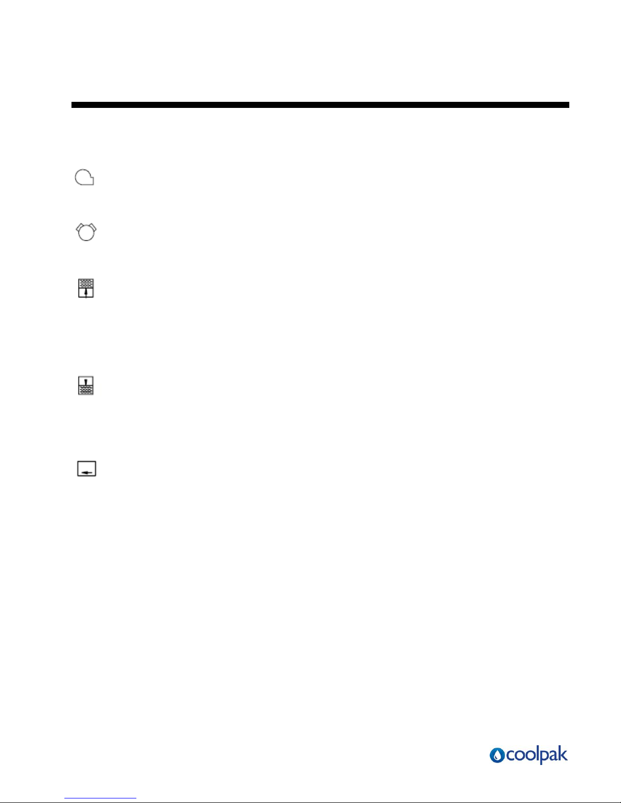
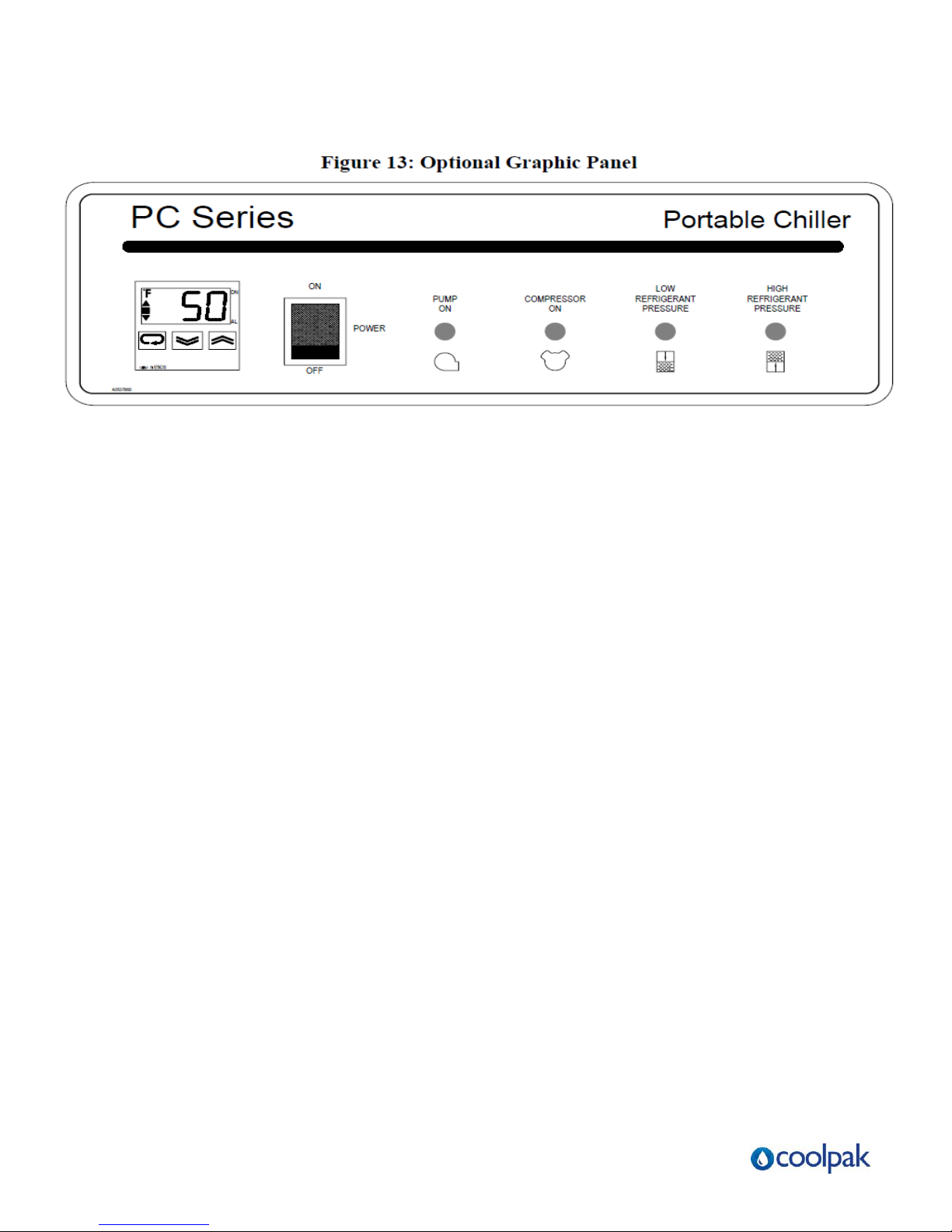
6-1 Indicator Lights
PUMP ON (green)
This indicator lights when the pump is running.
COMPRESSOR ON (green)
This indicator lights when the compressor is operating.
HIGH REFRIGERANT PRESSURE (red)
This indicator lights if the condensing pressure exceeds a safe level. The chiller goes to
Idle mode until the high refrigerant pressure cut-out resets. The light then goes out and
the chiller automatically restarts. Call a qualified refrigeration service technician for
service.
LOW REFRIGERANT PRESSURE (red)
This indicator lights if the refrigerant pressure drops below a safe level. The compressor will stop
and remain off until the pressure reaches a safe level. The light will go out and the chiller will then
resume operation automatically.
LOW WATER FLOW (red), PCA units without pump only
This indicator lights if the flow switch senses chilled water/glycol flow through the evaporator
dropping to an unacceptable level. The compressor will stop until the flow
switch senses adequate flow and restarts the chiller.
6-2 Switches
POWER
This switch energizes the control circuit and also turns off the chiller.
Page | 31
Page 32
Page | 32
Page 33
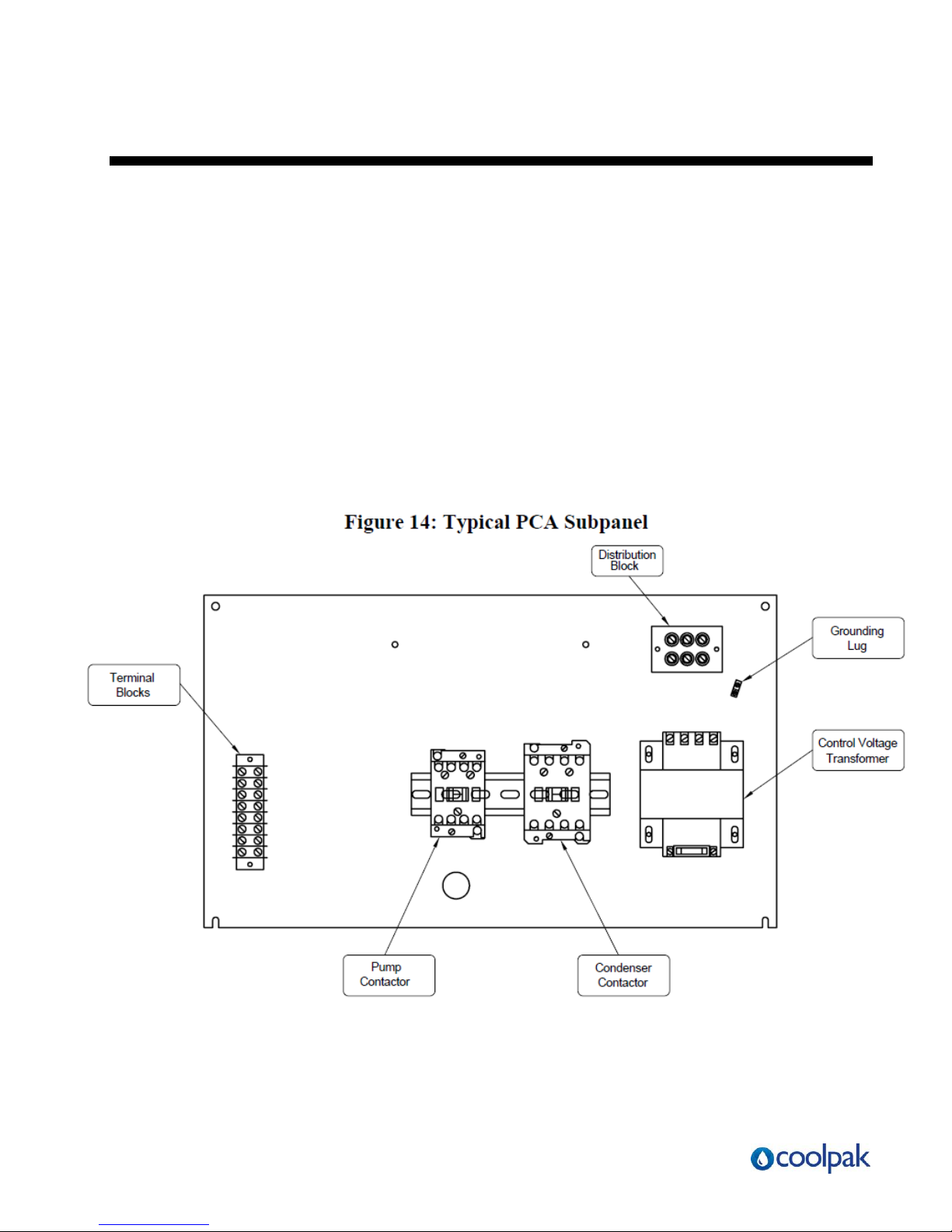
7 Routine Maintenance
7-1 Lubrication
Every three months, grease all fan motors and pump motors that do not have permanently
sealed bearings. Remove grease relief plug (motors only) before adding grease. Failure to
do so may result in dislodging the bearing grease retainer, eventually causing bearing
failure.
Compressors are hermetically sealed; no oiling is required.
7-2 Condenser Maintenance
Dirty condenser heat exchange surfaces reduce system capacity.
Brush or vacuum light dirt accumulations. Avoid bending or damaging the fins. Heavy soil
accumulations on the coil require professional steam cleaning; washing from the outside only
makes matters worse.
Page | 33
Page 34
Page | 34
Page 35
Page | 35
Page 36

~ Notes ~
Page | 36
Page 37

Page | 37
Page 38
Page | 38
Page 39
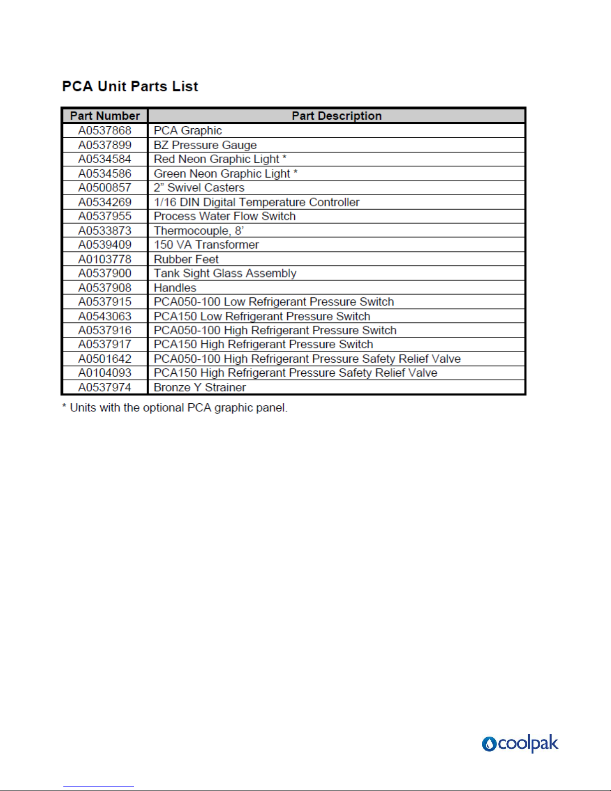
Page | 39
Page 40

~ Notes ~
Page | 40
Page 41

~ Notes ~
Page | 41
Page 42

~ Notes ~
Page | 42
Page 43

Contact Details
Australia Wide Phone: 1300 730 736
Australia Wide Fax: 1300 730 739
New Zealand Phone: 0800 442 569
International Phone: +61 2 8976 9200
International Fax: +61 2 8976 9299
Email: [email protected]
Sales NSW, QLD and New Zealand: Tim Fleming [email protected]
Sales VIC, ACT, WA, SA AND TAS: Stuart Mackenzie [email protected]
Customer Service: Anthea Harper [email protected]
Service: George Polles [email protected]
Dispatch: Paul Norman [email protected]
Coolpak Service will provide your company with genuine OEM quality parts manufactured to engineering design
specifications, which will maximize your equipment’s performance and efficiency. To assist in expediting your email,
phone or fax order, please have the model and serial number of your unit when you contact us. A customer replacement
parts list is included in this manual for your convenience. FLEMING DYNAMICS welcomes inquiries on all your parts
needs and is dedicated to providing excellent customer service.
Let us install your system. The Contract Department offers any or all of these services:
project planning; system packages including drawings; equipment, labor, and construction
materials; and union or non-union installations.
Page | 43
 Loading...