

Coolon CP56 User Manual
CP56 INDUSTRIAL LED MANUAL EDITION 1.8
Apply force
to t over
protruding
studs
Page 1 / 2
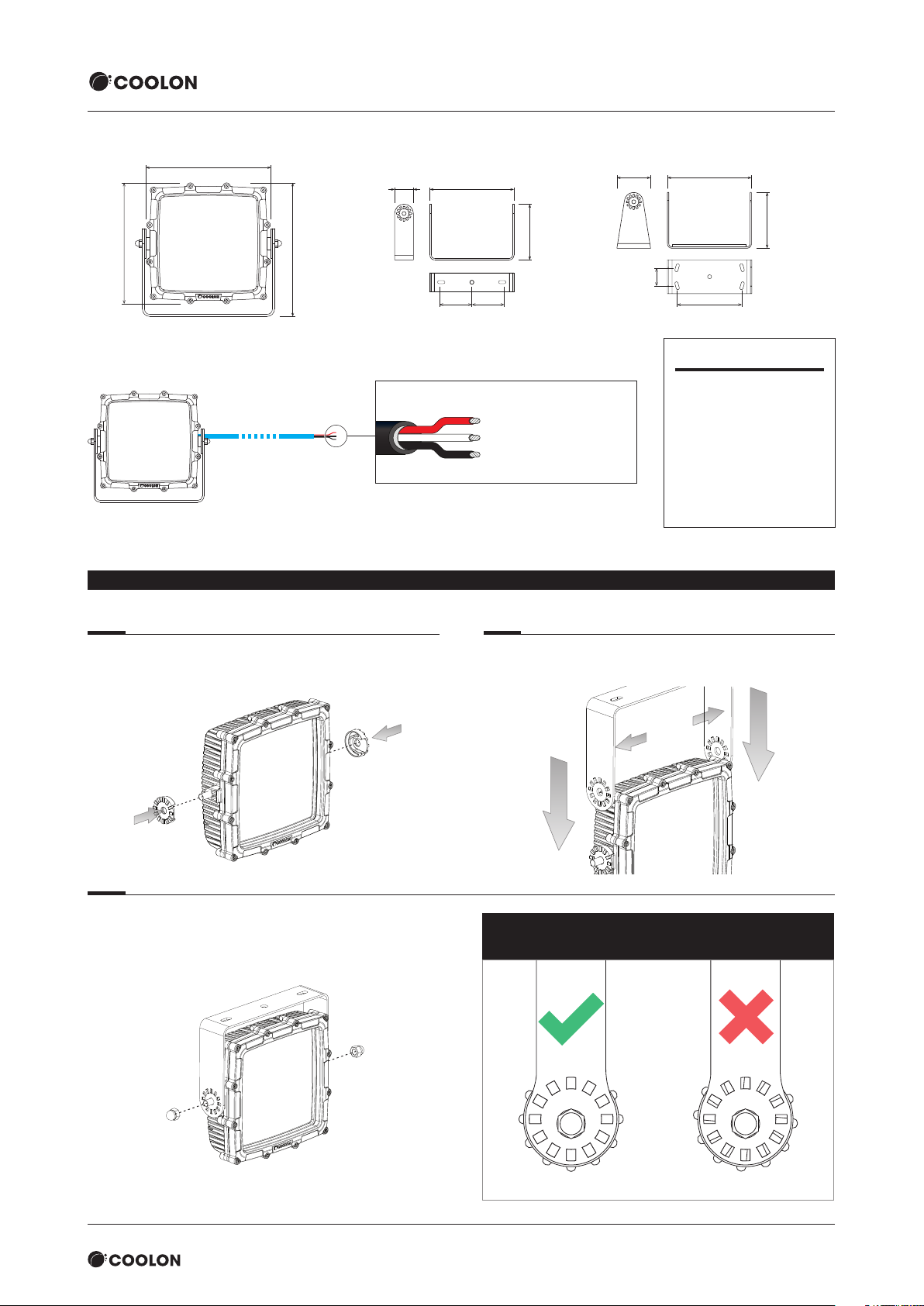
CP56 Luminaire
356mm
344mm
380mm
CP56-ELV
Length = 2m
24VD C IN
MOUNTING BRACKET INSTALLATION
Fixed Plant Bracket
MBR-CP56-FPB
84mm
364mm
145mm145mm
Wiring Diagram
Red (Positive)
White (0 – 10V Dimming)
Black (Negative)
208mm
Mobile Plant Bracket (Optional)
MBR-CP56-MPB
364mm150 mm
208mm
80mm
290mm
Electrical Characteristics
Voltage In
21 – 34VDC
Power
270W @24VDC
IP/IK Rating
IP66 / IK09
Operating Temperature
-20°C ≤ T
≤ 50°C
amb
Step 1
Install arm locks onto protruding studs on both sides of the
housing as shown below.
Step 3
Align perforated slots in mounting bracket against corresponding
notches in the arm locks, then tighten the nut. Ensure that all the
perforated slots sit firmly on the notches after tightening up the
nuts. Recommended tightening torque is 40 Nm.
Step 2
Apply necessary force to open the bracket in order to fit over the
properly positioned arm locks.
IM PO RTA NT: Ensure that all perforated slots sit firmly on
the notches af ter tightening up the dome nuts.
We recommend Loctite® 243™ retaining compound
(not included) to secure the dome nut.
Product must be installed by a suitably qualied person. All documentation is subject to change without notice. Refer to our website for the latest information.www.coolon.com.au
Page 1 / 2support@coolon.com.au • aus. 1300 287 533 • intl. +613 8681 3633 • www.coolon.com.au

Page 2 / 2CP56 INDUSTRIAL LED MANUAL EDITION 1.8
CP56 APPLICATION NOTE
Under some unique circumstances, a connection of multiple CP56 luminaires may result in the luminaires pulsing on and off (or flashing).
This application note addresses this phenomenon.
The CP56 Industrial LED Luminaire is built using on-board high ef ficiency switch mode drivers. It is designed to operate at a constant
power, however it reduces its power as the voltage at the input drops below its nominal operating range.
When the CP56 is powered from batteries, this method prevents current increase by reducing voltage when it is below the nominal
voltage which helps reduce battery damage and false tripping of circuit breakers.
The CP56 also has over voltage protection circuitry which ensures its reliable and safe operation on mobile plant equipment.
The Power vs Voltage graph below demonstrates the power consumption of the CP56 with respect to input voltage.
100
90
80
70
)
%
(
60
50
40
Power
30
20
10
0
0 5 10 15 20 25 30 35
Constant
Power Range
Voltage Input (V) Typical over voltage
cut-off level
The CP56 is designed to be connected to a low impedance 24VDC source such as a battery or a suitable Power Supply directly using its
2 meter cable.
Often an installation on mobile plant will use multiple CP56 units connected to a single point at the end of a single common cable
between the battery and distribution panel.
For this type of application, this common cable could be 15m long with 35mm² cross section. Such a cable provides low voltage drop,
however, it acts as an inductor with a high-quality factor (Q). The Q factor is defined as a ratio between Impedance at a particular
frequency ωL and DC resistance R.
ωL
Q = ——
R
The operating frequency of the CP56 drivers are sufficiently high (~300KHz or more). As a result of using a common cable, independent
drivers could start working in sync.
This creates peaks of high current going through the common par t of the cable.
As a result of cable inductance voltage spikes are generated at a common point which can exceed the cut-off voltage level and cause a
momentary shut-down of the CP56 on-board driver’s protection circuitry.
Externally this could be observed as a light flicker.
In order to avoid voltage spikes from happening, there are 2 common solution;
1. Independent cables for each CP56 is to be directly connected to the battery (in this case a 2.5 or 4mm² cross
section is sufficient for each luminaire), or
2. A capacitor bank (such as the CL-7DR-1000-24, Coolon 7 Channel DIN Rail Capacitor Bank 1000µF 24V)
should be employed to reduce the voltage spikes when independent cable extensions for individual CP56 units
are impractical.
NOTE: using a normal volt meter or a multimeter at this common point would not show increased voltage as a multimeter performs
averaging of the input voltage. In order to observe the voltage peaks a Digital Storage Oscilloscope (DSO) is needed.
IM PO RTANT
Primary use: flood light for commercial and industrial applications.
• Read thro ugh this manual b efore installat ion
• Handle the product with care
• The prod uct must be insta lled by a suitably q ualified perso n
Product must be installed by a suitably qualied person. All documentation is subject to change without notice. Refer to our website for the latest information.www.coolon.com.au
• Turn OFF the powe r before install ation and mainten ance
• Make sure th e product is secur ely installed
• The hous ing might become h ot after operatio n
• Keep optic al face clean
Page 2 / 2support@coolon.com.au • aus. 1300 287 533 • intl. +613 8681 3633 • www.coolon.com.au
 Loading...