

Page 1
CX-WIFI-2NET module user manual
Page 1 ,Total 93 Pages
CX-WIFI-2NET Module user
manual
Shenzhen Coolmay Technology Co.,Ltd
Version 7.21
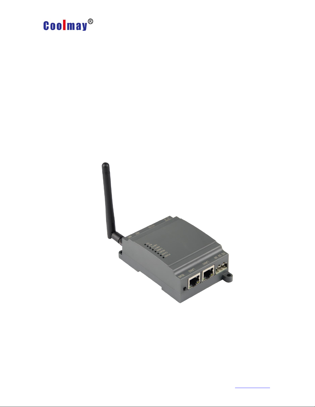
CX-WIFI-2NET module is an all-in-one 802.11 b/g/n Wi-Fi and Ethernet module that
provides a way to connect a user's physical device to a Wi-Fi wireless network or
Ethernet. Provides a solution for the UART data transfer interface. The module comes
with an RS485 port, a standard RS232 communication port and two RJ45 standard
network ports. Through this module, the traditional low-end serial device or
MCU-controlled device can easily access Wi-Fi wireless network or Ethernet.
Transparent transmission is realized to realize the control and management of the
Internet of Things.
As a hotspot, CX-WIFI-2NET module can accommodate 32 wifi clients simultaneously,
Shenzhen Coolmay Technology Co.,Ltd www.coolmay.com
Page 2

CX-WIFI-2NET module user manual
Page 2 ,Total 93 Pages
and can also accommodate 32 TCP clients at the same time. At the same time, the
module can be used as a secondary router and can be connected hand-in-hand.
Shenzhen Coolmay Technology Co.,Ltd www.coolmay.com
Page 3

CX-WIFI-2NET module user manual
Page 3 ,Total 93 Pages
Contents
Contents........................................................................................................................ 3
Chapter 1 Hardware description ................................................................................... 6
1.1. Module model and appearance ....................................................................... 6
1.2. Indicator function ............................................................................................. 7
1.3 Features............................................................................................................ 8
1.4 Main application areas ...................................................................................... 8
1.5 Module basic parameters ................................................................................. 9
Chapter 2 Product function description ....................................................................... 10
2.1 User configuration process ............................................................................. 10
2.2 Operating mode .............................................................................................. 10
2.2.1 Transparent transmission mode ............................................................ 10
2.2.2 Serial command mode ........................................................................... 11
2.2.3 HTTPD Client mode .............................................................................. 12
2.2.4 Modbus TCP and Modbus RTU mutual conversion ............................... 13
2.3 Wireless networking ........................................................................................ 14
2.3.1 STA-based wireless network ................................................................. 14
2.3.2 AP-based wireless network ................................................................... 15
2.3.3 AP+STA wireless network ...................................................................... 16
2.4 Ethernet interface networking mode ............................................................... 17
2.4.1 CX-WIFI-2NET module Ethernet interface function (AP) ....................... 17
2.4.2 CX-WIFI-2NET module Ethernet interface function (STA routing mode) 18
2.4.3 CX-WIFI-2NET module Ethernet interface function (STA bridge mode) 18
2.4.4 CX-WIFI-2NET Ethernet interface function (switch) .............................. 19
2.5 WI-FI parameter settings ................................................................................ 19
2.5.1 Automatic frequency selection ............................................................... 19
2.5.2 Security Mechanism .............................................................................. 19
2.5.3 Add router function when STA ............................................................... 20
2.5.4 STA address binding function ................................................................ 21
2.6 Network parameter setting .............................................................................. 21
2.6.1 Socket A ................................................................................................ 21
2.6.2 Socket B ................................................................................................ 22
2.7 New feature settings ....................................................................................... 22
2.7.1 Tcp password authentication when establishing connection .................. 22
2.7.2 Register ID/MAC function ...................................................................... 22
2.7.3 Adaptive baud rate function ................................................................ ... 23
2.7.4 KeepAlive Function ................................................................................ 24
2.7.5 Multi-STA Function ................................................................................ 24
2.7.6 Domain name backup and smart STA ................................................... 24
2.8 Parameter setting ........................................................................................... 24
2.9 Firmware upgrade ........................................................................................... 25
Chapter 3 Module parameter setting ........................................................................... 26
3.1 Web Management page .................................................................................. 26
3.1.1 Open management page ............................................................................. 26
3.1.2 Quick Configuration ............................................................................... 27
3.1.3 Wireless Mode Selection ....................................................................... 27
3.1.4 Wireless Access Point Settings ........................................................... 28
Shenzhen Coolmay Technology Co.,Ltd www.coolmay.com
Page 4

CX-WIFI-2NET module user manual
Page 4 ,Total 93 Pages
3.1.5 Wireless Terminal Settings .................................................................... 29
3.1.6 Serial Port and Network Settings ........................................................... 31
3.1.7 Ethernet Function Settings .................................................................... 32
3.1.8 HTTPD Client Mode .............................................................................. 33
3.1.9 Advanced setting ................................................................................... 34
3.1.10 Module Management ................................ ................................ ........... 34
3.2 Serial Port Configuration ................................................................................. 35
3.2.1 Module operation mode ......................................................................... 35
3.2.1.1 Switch transparent mode to command mode ............................... 37
3.2.2 AT+ Command instruction ..................................................................... 37
3.2.2.1 Command format .......................................................................... 39
3.2.2.2 Instruction Set .............................................................................. 41
3.2.2.2.1 AT+E ................................................................................... 44
3.2.2.2.2 AT+ENTM ............................................................................ 44
3.2.2.2.3 T+NETP .............................................................................. 44
3.2.2.2.4 AT+UART ............................................................................ 44
3.2.2.2.5 AT+UARTF .......................................................................... 45
3.2.2.2.6 AT+UARTFT ........................................................................ 45
3.2.2.2.7 AT+UARTFL ........................................................................ 46
3.2.2.2.8 AT+TMODE ......................................................................... 46
3.2.2.2.9 AT+WMODE ........................................................................ 46
3.2.2.2.10 AT+WSKEY ....................................................................... 47
3.2.2.2.11 AT+WSSSID ...................................................................... 48
3.2.2.2.12 AT+WSLK .......................................................................... 48
3.2.2.2.13 AT+WEBU ......................................................................... 48
3.2.2.2.14 AT+WAP ............................................................................ 49
3.2.2.2.15 AT+WAKEY ....................................................................... 49
3.2.2.2.16 AT+MSLP .......................................................................... 50
3.2.2.2.17 AT+WSCAN ...................................................................... 51
3.2.2.2.18 AT+TCPLK ........................................................................ 51
3.2.2.2.19 AT+TCPDIS ....................................................................... 51
3.2.2.2.20 AT+WANN ......................................................................... 52
3.2.2.2.21 AT+LANN .......................................................................... 53
3.2.2.2.22 AT+DHCPGW ................................................................... 53
3.2.2.2.23 AT+TCPTO ........................................................................ 54
3.2.2.2.24 AT+MAXSK ....................................................................... 54
3.2.2.2.25 AT+TCPB .......................................................................... 54
3.2.2.2.26 AT+TCPPTB ...................................................................... 55
3.2.2.2.27 AT+TCPADDB ................................................................... 55
3.2.2.2.28 AT+TCPTOB ..................................................................... 56
3.2.2.2.29 AT+TCPLKB ...................................................................... 56
3.2.2.2.30 AT+FUDLX ........................................................................ 56
3.2.2.2.31 AT+MMID .......................................................................... 57
3.2.2.2.32 AT+IDFIR .......................................................................... 57
3.2.2.2.33 AT+IDEVE ......................................................................... 57
3.2.2.2.34 AT+AABR .......................................................................... 57
3.2.2.2.35 AT+DHCPDEN .................................................................. 58
3.2.2.2.36 AT+HIDESSID ................................................................... 58
3.2.2.2.37 AT+DOMAIN ..................................................................... 58
Shenzhen Coolmay Technology Co.,Ltd www.coolmay.com
Page 5

CX-WIFI-2NET module user manual
Page 5 ,Total 93 Pages
3.2.2.2.38 AT+RELD .......................................................................... 59
3.2.2.2.39 AT+Z .................................................................................. 59
3.2.2.2.40 AT+MID ............................................................................. 59
3.2.2.2.41 AT+VER ............................................................................ 59
3.2.2.2.42 AT+H ................................................................................. 60
3.2.2.2.43 AT+HTTPURL ................................................................... 60
3.2.2.2.44 AT+HTTPTP ...................................................................... 60
3.2.2.2.45 AT+HTTPPH ..................................................................... 61
3.2.2.2.46 AT+HTTPCN ..................................................................... 61
3.2.2.2.47 AT+HTTPUA ..................................................................... 61
3.2.2.2.48 AT+EPHYA ........................................................................ 62
3.2.2.2.49 AT+EPHYB ........................................................................ 62
3.2.2.2.50 AT+WSSSIDA ................................................................... 62
3.2.2.2.51 AT+WSSSIDB ................................................................... 63
3.2.2.2.52 AT+WSSSIDC ................................ ................................ ... 63
3.2.2.2.53 AT+WSKEYA ..................................................................... 64
3.2.2.2.54 AT+WSKEYB .................................................................... 65
3.2.2.2.55 AT+WSKEYC .................................................................... 65
3.2.2.2.56 AT+WSQY ......................................................................... 66
3.2.2.2.57 AT+HTPMODE .................................................................. 67
3.2.2.2.58 AT+HTPSV ........................................................................ 67
3.2.2.2.59 AT+HTPTP ........................................................................ 68
3.2.2.2.60 AT+HTPURL ..................................................................... 68
3.2.2.2.61 AT+HTPHEAD ................................................................... 69
3.2.2.2.62 AT+REGEN ....................................................................... 69
3.2.2.2.63 AT+REGTCP ..................................................................... 69
3.2.2.2.64 AT+REGID ........................................................................ 70
3.2.2.2.65 AT+IPBUP ......................................................................... 70
3.2.2.2.66 AT+STAPRO ..................................................................... 71
3.3 AP Mode Setting Procedure ............................................................................ 72
3.4 STA mode setting procedure ........................................................................... 77
Appendix A: FAQ and Answers ................................................................................... 88
Question 1: Two CX-WIFI-2NET modules are interconnected, and the TCP protocol
is used as a transparent serial port. How to set it? ............................................... 88
Question 2:CX-WIFI-2NET module LAN IP settings, WAN IP settings Where are
they set? ............................................................................................................... 88
Question 3: Two WIFI modules are interconnected, and the transparent serial port
is made by UDP protocol. How to set it?............................................................... 89
Question 4: Where is the TCP/UDP protocol of the CX-WIFI-2NET module? ...... 90
Question 5: Two WIFI modules are set as STAs, which are interconnected by APs
and do transparent serial ports. How to set them? ............................................... 91
Question 6:
How to avoid IP address conflict when using CX-WIFI-2NET module?
.............................................................................................................................. 91
Question 7: The WIFI module is connected to the PC (Server) as a data acquisition
card. How to set it? ............................................................................................... 92
Question 8: Does the WIFI module TCP support UDP multicast?
................... 93
Question 9: The WIFI module works in STA mode. How does the host computer
obtain the IP of the module?
............................................................................... 93
Shenzhen Coolmay Technology Co.,Ltd www.coolmay.com
Page 6
CX-WIFI-2NET module user manual
Page 6 ,Total 93 Pages
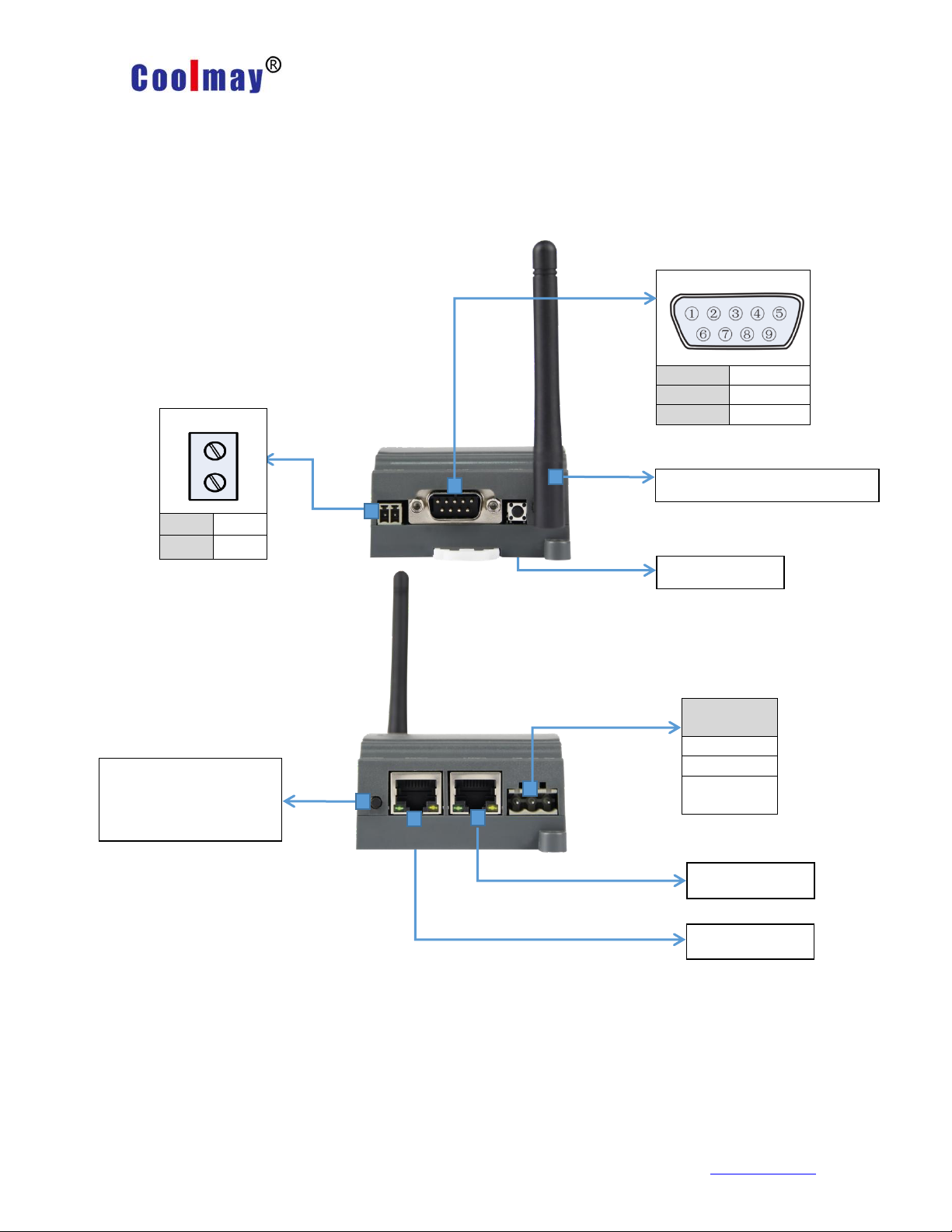
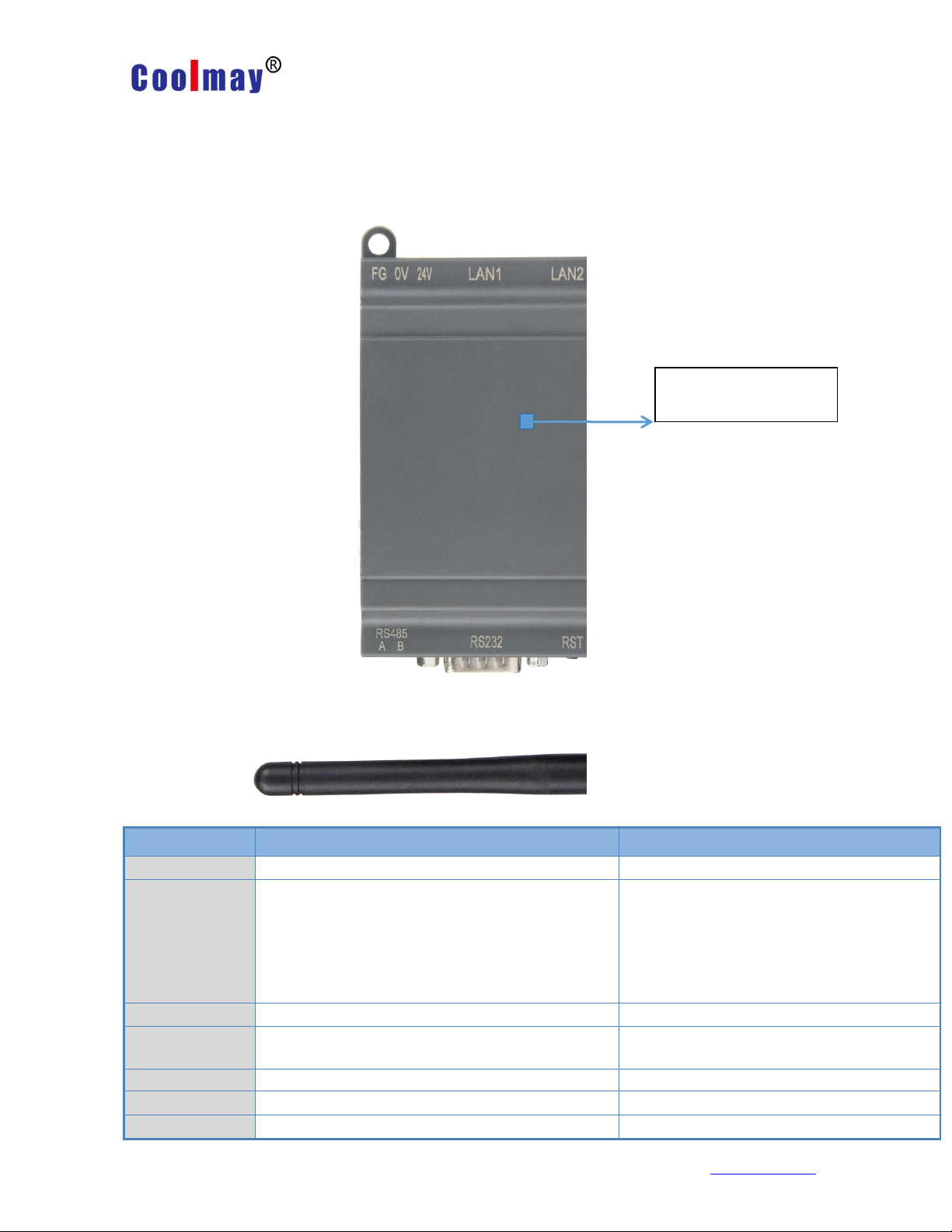
RJ45 LAN2
Restart button
RS485
A
485+
B
485-
RS232
2
RX
3
TX 5 GND
Power
terminal
24V+
24V-
Ground
wire
Restore factory settings
button
Long press around 5S
External antenna detachable
RJ45 LAN1
Chapter 1 Hardware description
1.1. Module model and appearance
Shenzhen Coolmay Technology Co.,Ltd www.coolmay.com
Page 7
CX-WIFI-2NET module user manual
Page 7 ,Total 93 Pages
Indicator
Indication function
Status
POWER
Power Indicator
Power supply works normally.
CHAR
Lithium battery charging indicator
(optional)
It is equipped with a lithium battery
and is always on when the
rechargeable battery is charging. It
automatically turns off when the
battery is fully charged.
READY
System operation work indicator
Always bright after the system is
LINK
Module WIFI connection status indication
Connection is established with
data constantly lit
NET1
LAN1 port connection status indicator
Connection establishment has data
NET2
LAN2 port connection status indicator
Connection establishment has data
RX
Data transmission indication
Serial network RX has data flashing
See the table below for
the indicator function
1.2. Indicator function
There are eight indicators on CX-WIFI-2NET module, which are POWER, CHAR,
READY, LINK, NET1, NET2, RX, TX. The status of the indicator light is as follows:
Shenzhen Coolmay Technology Co.,Ltd www.coolmay.com
Page 8

CX-WIFI-2NET module user manual
Page 8 ,Total 93 Pages
TX
Data transmission indication
Serial network TX has data flashing
1.3 Features
● Support 802.11b/g/n wireless standard
● Support TCP/IP/UDP network protocol stack
● Support UART/Ethernet data communication interface
● Support wireless work in STA/AP/AP+STA mode
● Support routing / bridging / switch mode network architecture
● Support transparent / protocol data transmission mode
● Provide web configuration page
● Support heartbeat signal, WIFI connection indication
● Support serial free/auto framing function
● Flexible software platform to provide customized services
1.4 Main application areas
◆ Intelligent lighting
◆ Smart socket
◆ Industrial control
◆ Remote device monitoring
◆ Internet of Things applications
Shenzhen Coolmay Technology Co.,Ltd www.coolmay.com
Page 9

CX-WIFI-2NET module user manual
Page 9 ,Total 93 Pages
Item
Index
Wireless
parameter
Wireless standard
802.11 b/g/n
Frequency range
2.412GHz-2.484GHz
Transmit power
802.11b: +20dBm(Max.)
802.11g: +18dBm(Max.)
802.11n: +15dBm(Max.)
User can configure power
Receiving sensitivity
802.11b: -89dBm
802.11g: -81dBm
802.11n: -71dBm
Antenna option
External I-PEX connector
Hardware
parameter
Data interface
UART:300bps-460800bps
Ethernet:100Mpbs
Operating Voltage
5-30V
Working current
50mA~350mA
Operating temperature
-40℃-85℃
Storage temperature
-40℃-125℃
Size
65×90×36mm
Software
parameter
Wireless network type
Station/AP mode
Security Mechanism
WEP/WPA-PSK/WPA2-PSK
Encryption type
WEP64/WEP128/TKIP/AES
Operating mode
Transparent transmission mode, serial
command mode
AT command
AT+ command structure
Network protocol
TCP/UDP/ARP/ICMP/DHCP/DNS/HTTP
Maximum number of
TCP connections
32
User configuration
Web server + AT command
configuration
1.5 Module basic parameters
Shenzhen Coolmay Technology Co.,Ltd www.coolmay.com
Page 10

CX-WIFI-2NET module user manual
Page 10 ,Total 93 Pages
Chapter 2 Product function description
2.1 User configuration process
After CX-WIFI-2NET module is powered on, it will automatically connect to the
wireless network and server according to the parameters set by the user, and enter the
set working mode, and open the serial port according to the preset serial port
parameters.
The parameters that the user needs to preset are:
Operating mode
Transparent transmission / serial command mode / HTTPD Client mode
Wireless network parameters
Network name (SSID)
Safe mode
Key
Default TCP/UDP connection parameters
Protocol type
Connection type (server or client)
Destination port
Destination IP address
Serial port parameter
Baud rate
Data bit
Check position
Stop bit
Hardware flow control
After the user has configured all the parameters and restarted, the module can
work according to the set parameters. Each section will be described in detail in the
following sections.
2.2 Operating mode
The module has three working modes: transparent transmission, serial command
mode, and HTTPD client mode.
2.2.1 Transparent transmission mode
CX-WIFI-2NET module supports serial port transparent transmission mode, which
can realize serial port plug and play, thus minimizing the complexity of user use. In this
mode, all data that needs to be sent and received is transparently transmitted between
the serial port and the WiFi or Ethernet interface, enabling data transfer between the
universal serial device and the network device without any analysis.
In transparent transmission mode, it can be fully compatible with the user's original
software platform. User equipment can support wireless data transmission without any
software changes.
Shenzhen Coolmay Technology Co.,Ltd www.coolmay.com
Page 11

CX-WIFI-2NET module user manual
Page 11 ,Total 93 Pages
Baotou
Length
Functional
word
Alternate
parameter area
Target
port
Target
address
Data
Sum
check
2
2
(n+m+5)
1 2 2 m n
1
<Description>:
Transparent transmission mode is the least complex data transmission. The user
turns on the hardware flow control (CTS/RTS) function of the serial port, which can
minimize the bit error rate.
2.2.2 Serial command mode
In this mode, users can send serial port data to different server addresses
according to our protocol, and send data to different servers without restarting. This
mode can send data to the server using UDP or TCP client.
The client MCU sends the packet in the following format. After the module is parsed,
only n bytes of data are sent to the destination address. When there is data return, the
data is directly output from the serial port without parsing.
Serial command mode protocol table:
Baotou:
Constant for 0x55 0xaa
Length:
The sum of all the number of bytes from the start of the function word to the check
(without the checksum). High byte first function word:
Bit0:( UDP:0 ;TCP:1)
Bit1:( Short connection: 0; long connection:1)
Bit2:( IP:0;Domain name:1)
Bit7:( Streamlined protocol: 0; Full protocol:1)Note: Currently only the streamlined
protocol is supported.
Note:
● For Bit1, if it is a short connection, the data will be disconnected after sending the
data; if it is a long connection, after the data is sent, the connection will remain until the
target address is changed again.
● For Bit2, it indicates whether the destination address is IP or domain name. If it is
IP, the destination address is 4 bytes. If it is a domain name, the target address length
is the length of the entire domain name string (where the last byte of the destination
address is 0x00). , that is, the end of the string, the length of the domain name is not
fixed).
● For Bit7, in the thin protocol, the reply frame contains only data. Under the full
protocol, the reply frame will have a frame failure such as sending failure, waiting for
timeout, and responding to the device IP under UDP broadcast.
Alternate parameter area:
The first byte: If it is a short connection, this location is the TCP wait timeout period
(1-255). If the response is not received after the send command is completed, wait for
the corresponding number of seconds. If it is 5, it means the maximum wait. 5s
disconnected; if the return data is received immediately after sending the command,
the connection is immediately disconnected; if it is a long connection, it is 0x00 here.
Shenzhen Coolmay Technology Co.,Ltd www.coolmay.com
Page 12

CX-WIFI-2NET module user manual
Page 12 ,Total 93 Pages
Second byte: reserved
Target port:
Little endian format, low byte first, such as port 23, here the order is 17 00
Target address:
If it is IP, it is 4 bytes, for example, 192.168.0.7 is represented as 07 00 A8 C0; if it
is a domain name, the address length is not fixed, ending with '\0'
Data:
Variable length, up to 1000 bytes
Calibration:
From the beginning of the function word, before the check byte, add the checksum.
The following are specific application examples:
Send data: 55 aa 00 0a 00 00 00 21 00 85 00 A8 C0 01 0f
Length byte 00 0a: length is n+m+5, here is 10
Function word 00: UDP mode
Target ip address 85 00 A8 C0:192.168.0.133
Data area 00: length is 1
Check calculation:
0x00+0x00+0x00+0x21+0x00+0x85+0x00+0xA8+0xC0+0x01=0x0f
2.2.3 HTTPD Client mode
This mode is used to request data from an HTTP server or to submit data to a
server.
After the user sets the specific content of the HTTP protocol header with the AT
command or the web page. Each time data is sent, the module automatically
encapsulates the sent data into HTTP protocol data and sends it to the specified HTTP
server. It is convenient for users to read or submit data directly from the HTTP server. In
this mode, the user can send the data to the specified http server, and the module will
automatically add the http protocol header in front of the sent data. The content of the
specific protocol header can be set by the AT command or the web page.
The following are specific application examples:
First set the HTTP related parameters with the AT command.
AT+HTTPURL=192.168.1.1,80 Set the server's address and port
AT+HTTPTP=POST Set the HTTP type, GET, PUT,
or POST
AT+HTTPPH=/set Set the path in the protocol
header, up to 50 bytes
AT+HTTPCN=keep-alive Set Connection in the protocol
header, up to 20 bytes
AT+HTTPUA=lwip13.2 Set the User-Agent in the protocol
header, up to 20 bytes.
If the data sent is 1234.
Then on the 192.168.1.1 port 80 will receive the following data
POST/set HTTP/1.1
Connection:keep-alive
User-Agent:lwip1.3.2
Content-Length:4
Host:192.168.1.1:80
Shenzhen Coolmay Technology Co.,Ltd www.coolmay.com
Page 13

CX-WIFI-2NET module user manual
Page 13 ,Total 93 Pages
1234
If the HTTP type is GET, the data received on port 80 of 192.168.1.1 is
POST/set1234 HTTP/1.1
Connection:keep-alive
User-Agent:lwip1.3.2
Content-Length:0
Host:192.168.1.1:80
If the module receives data from the server, it will print directly to the serial port
without any processing.
Users can customize the content of the HTTP header in the new definition mode.
You can add, delete, and modify the content of each HTTP header according to your
needs. (If the HTTP request type is POST/PUT, the module will automatically add
Content-Length. ). The set commands include AT+HTPMODE, AT+HTPSV, AT+HTPTP,
AT+HTPURL, AT+HTPHEAD. For the specific command setting procedure, please
refer to the AT command section. Similarly, there are corresponding settings pages in
the web page.
Note: In the new setting mode, if you use the AT command to set the protocol
header, please use "<<CRLF>>" instead of the carriage return. You don't need to
consider the carriage return when setting the built-in webpage.
2.2.4 Modbus TCP and Modbus RTU mutual conversion
This module supports Modbus TCP to Modbus RTU (Modbus ASCII is not
supported); the network parameters of the module should correspond to the network
parameters of the application software. The TCP server corresponds to the TCP client,
and the port should also be configured to be the same. The working mode is Modbus
TCP<= >Modbus RTU (AT command: AT+TMODE=modbus).
Shenzhen Coolmay Technology Co.,Ltd www.coolmay.com
Page 14
CX-WIFI-2NET module user manual
Page 14 ,Total 93 Pages
User equipment
T C P 2 3 2 -4 0 1
P C
ModbusRTU to ModbusTCP
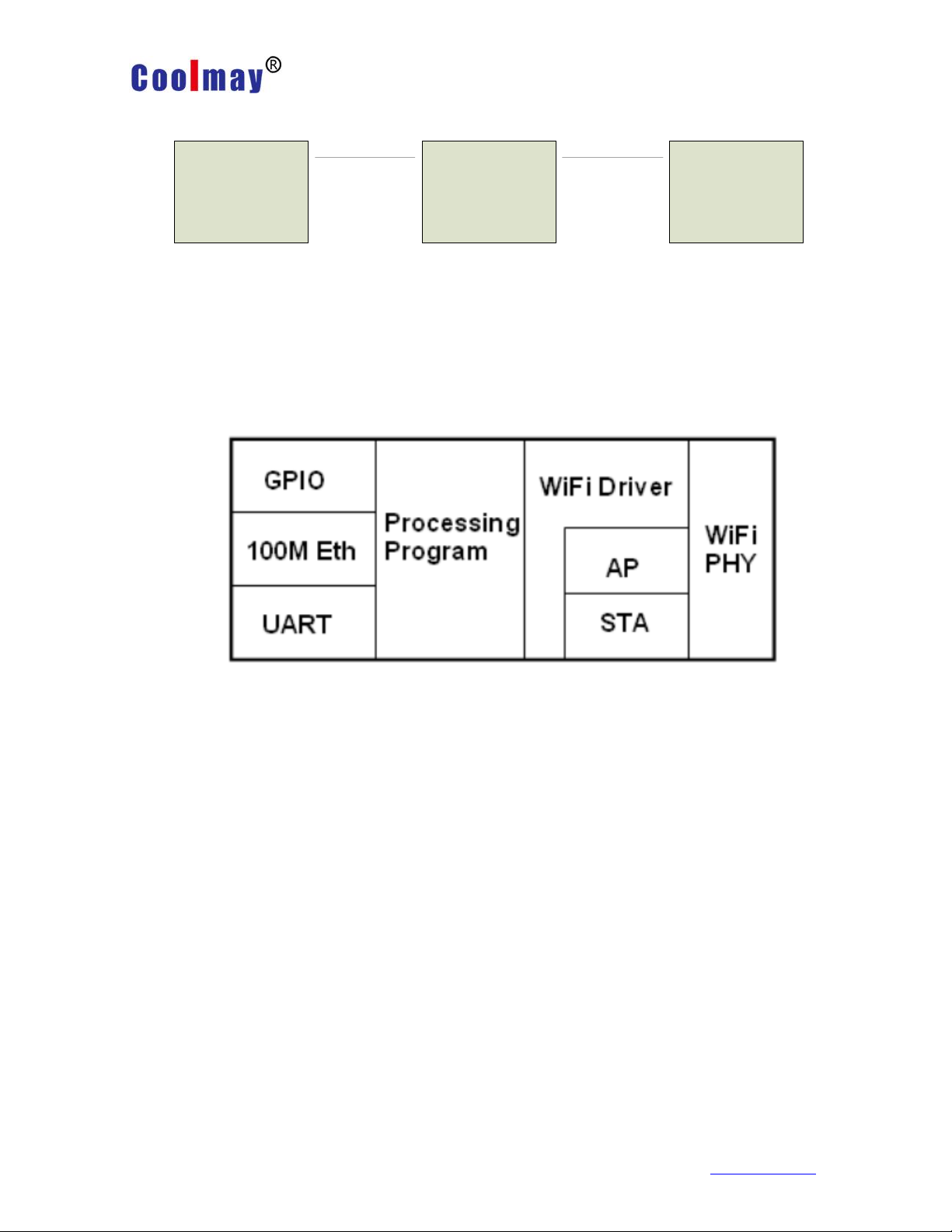
2.3 Wireless networking
The wireless module of the CX-WIFI-2NET module can be configured as a wireless
STA or as an AP. Therefore, the CX-WIFI-2NET module logically supports two wireless
interfaces, one as a STA and the other as an AP. Other STAs can connect to the
wireless network through the AP interface of this module. Therefore, the
CX-WIFI-2NET module can provide a very flexible networking mode and network
topology. The functional modules of the CX-WIFI-2NET module are shown below:
< Description >:
AP: The wireless access point is the central node of a wireless network. A
commonly used wireless router is an AP, and other wireless terminals can be
connected to each other through an AP.
STA: A wireless station is a terminal of a wireless network. Such as laptops, PDAs,
etc.
2.3.1 STA-based wireless network
The CX-WIFI-2NET module is connected to other APs as STAs (using the AP CLI interface) to
form a wireless network. All STAs use the AP as the center of the wireless network, and the mutual
communication between the STAs is completed by the AP. As shown below:
Shenzhen Coolmay Technology Co.,Ltd www.coolmay.com
Page 15
CX-WIFI-2NET module user manual
Page 15 ,Total 93 Pages
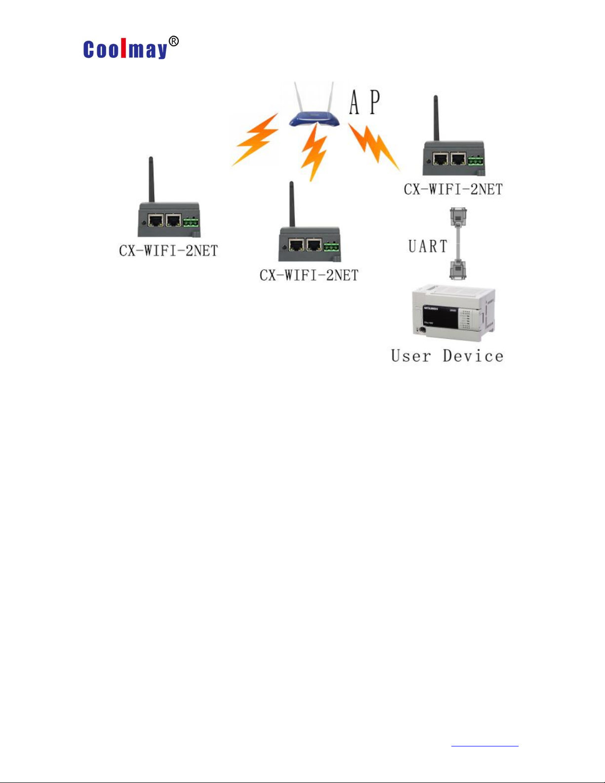
2.3.2 AP-based wireless network
Because the CX-WIFI-2NET module can be set to either AP or STA, the CX-WIFI-2NET
module can easily implement the wireless network of the ad hoc network. As shown below. The
CX-WIFI-2NET module No. 1 is used as an AP. Other modules and computers can be connected to
this module as STAs. It can also be connected to user equipment through the UART interface;
CX-WIFI- 2 and 3 The 2NET module is connected to the No. 1 module as a STA, so that all
CX-WIFI-2NET modules can be managed by a computer. The self-organizing network mode can
facilitate the unified management of all CX-WIFI-2NET modules, and the self-organizing network
can easily expand the coverage of the entire wireless network.
Shenzhen Coolmay Technology Co.,Ltd www.coolmay.com
Page 16
CX-WIFI-2NET module user manual
Page 16 ,Total 93 Pages
2 号
No.3
No.1
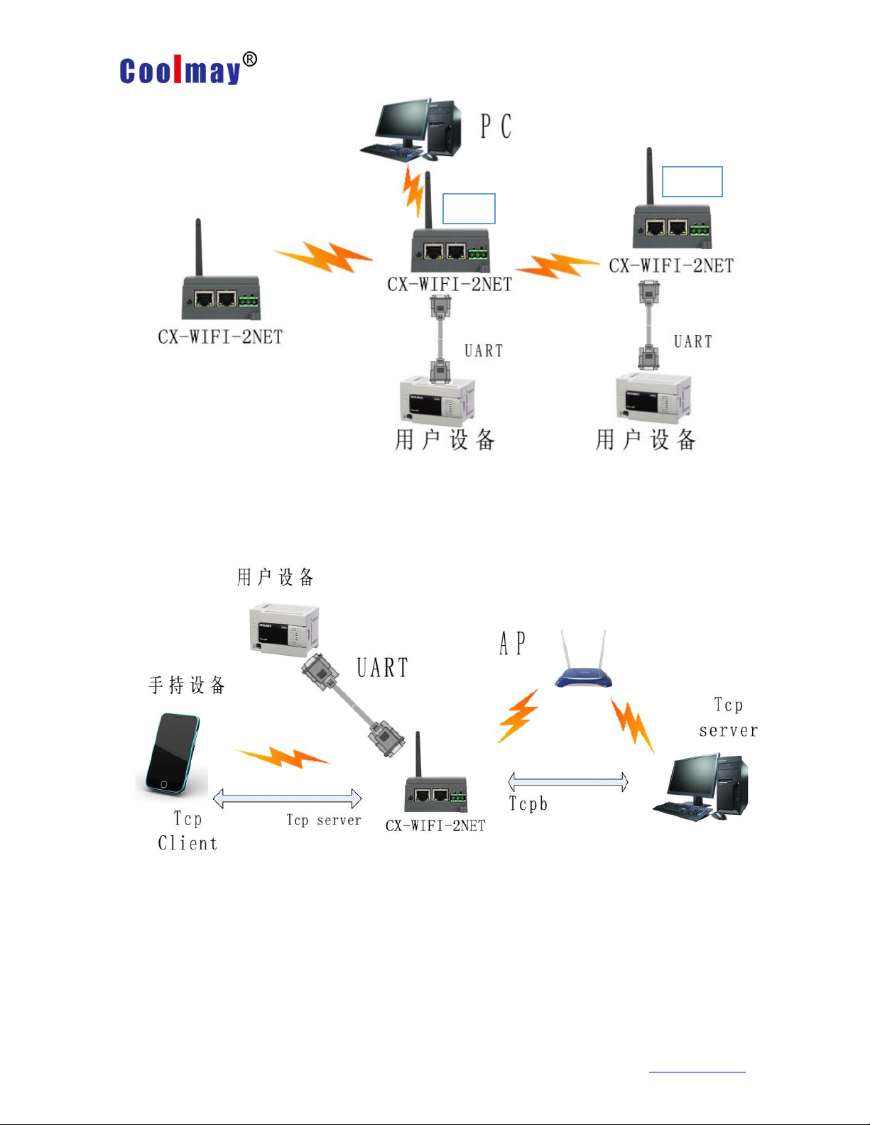
2.3.3 AP+STA wireless network
The CX-WIFI-2NET module can support AP+STA. That is, the module supports
one AP interface and one STA interface at the same time.
In the figure, the module activates the function of AP+STA. The STA interface of the
module can be connected to the router and connected to the server in the network
through TCP connection. At the same time, the AP interface on the module is also
available. The mobile phone/PAD can be connected to this AP interface (via TCPB
connection) to control the serial device or set the module.
☆ With the AP+STA function, it is convenient to use the mobile phone/PAD and
other hand-held devices to monitor the user device without changing its original
network settings.
Shenzhen Coolmay Technology Co.,Ltd www.coolmay.com
Page 17
CX-WIFI-2NET module user manual
Page 17 ,Total 93 Pages
☆ The module can be easily set by the AP+STA function, which solves the
problem that the previous module can only be set through the serial port when it is in
the STA.
AP+STA Function setting:
The AP+STA function needs to be set through the serial port command
(F-logarithmic setting).
AT+FAPSTA=on Sets the AP+STA function (the factory settings are in effect).
Then when the module is set to STA mode, the AP interface is still valid.
Note on AT+STA mode:
When the AP+STA function is enabled, the STA port needs to be connected to
other routers. Otherwise, the STA port will continuously scan the router. When scanning,
it will affect the AP port, such as data loss.
If the user determines that the STA cannot connect to the AP at this time, you can
use the command to stop scanning the STA port.
AT+STTC=on/off, on means scanning the router, off is not scanning, and the
command is not saved after restarting.
AT+FSTTC=on/off, this command can be saved, and the original settings will be
maintained after restarting.
2.4 Ethernet interface networking mode
The CX-WIFI-2NET module provides a 100M Ethernet interface. Through this
100M Ethernet interface, users can implement WIFI port, serial port, Ethernet port, and
three interfaces to communicate with each other. In terms of networking, the
CX-WIFI-2NET module supports bridging mode, routing mode and switch mode to
correspond to different specific applications.
<Description>:
The Ethernet function has two network ports. The second network port can be used
as either a LAN port or a WAN port. The first network port can only be used as a LAN.
The bridge mode described below uses only the network port 2. The route mode can
use either network port 1 or network port 2. The switch mode uses two network ports at
the same time.
For different networking modes, the CX-WIFI-2NET module needs to be
version-switched through commands. Use the command AT+FVER=n to switch to the
(2.4.2) routing mode, and AT+FVER=z to switch to the (2.4.3) bridge mode.
2.4.1 CX-WIFI-2NET module Ethernet interface function (AP)
Shenzhen Coolmay Technology Co.,Ltd www.coolmay.com
Page 18
CX-WIFI-2NET module user manual
Page 18 ,Total 93 Pages
Ethernet interface function (AP)
CX-WIFI-2NET module Ethernet interface function (AP+ dual network port)
The CX-WIFI-2NET module functions as an AP and forms a network centered on
the module. The IP addresses of all devices on the network work in the same network
segment as the modules.
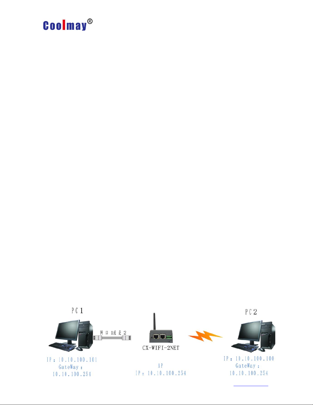
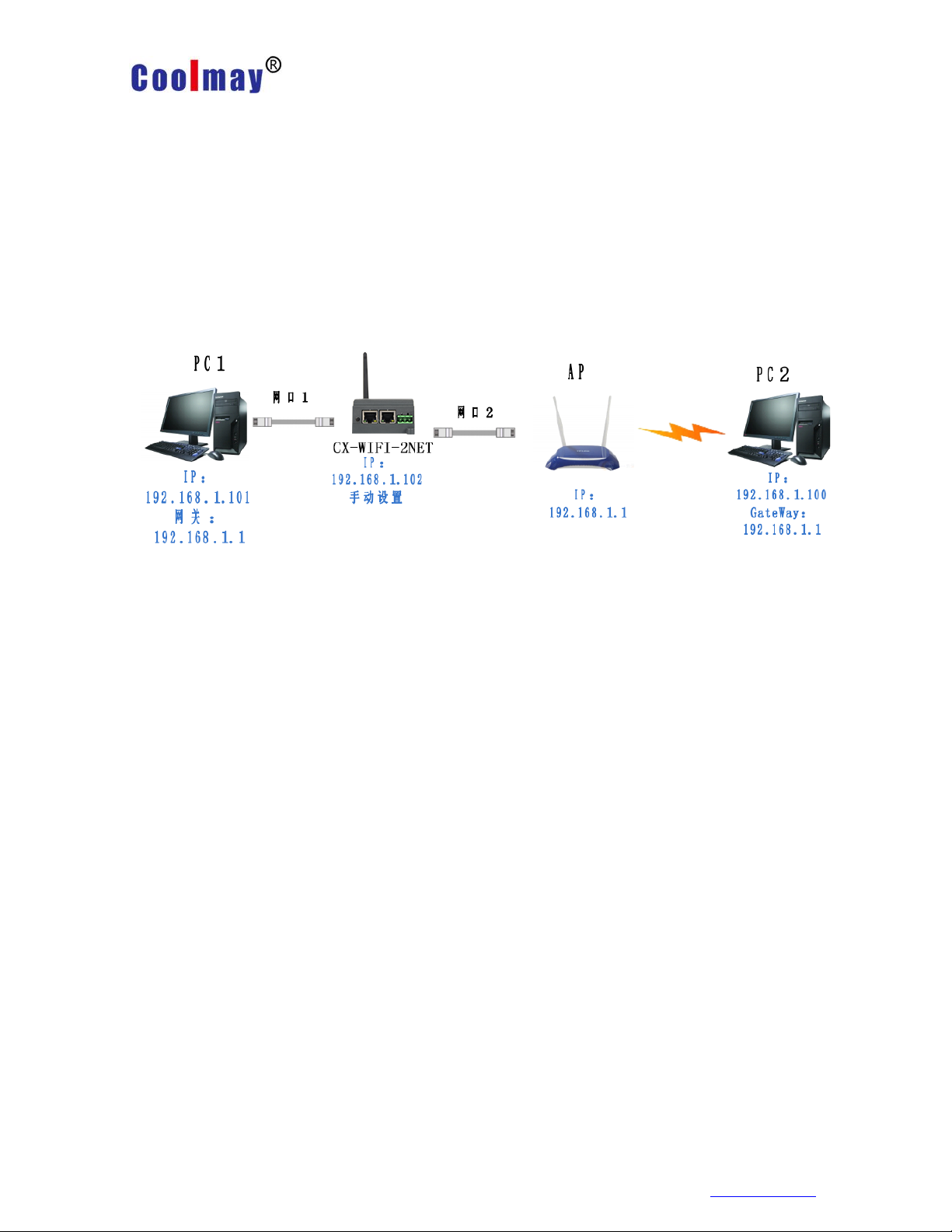
2.4.2 CX-WIFI-2NET module Ethernet interface function (STA routing mode)
CX-WIFI-2NETModule Ethernet interface function(STA)
The CX-WIFI-2NET block acts as a STA and the module works in routing mode.
After the module is connected to the AP, obtain the IP address from the AP (as shown
in Figure 192.168.1.100). The modules themselves form a subnet (default
10.10.100.254), and the devices on the Ethernet interface are assigned addresses by
the module (see Figure 10.10.100.101). Thus, as PC1 is in the subnet (NAT), the
connection from PC1 can be connected to PC2 (because CX-WIFI-2NET works in
routing mode), but PC2 cannot actively connect to PC1.
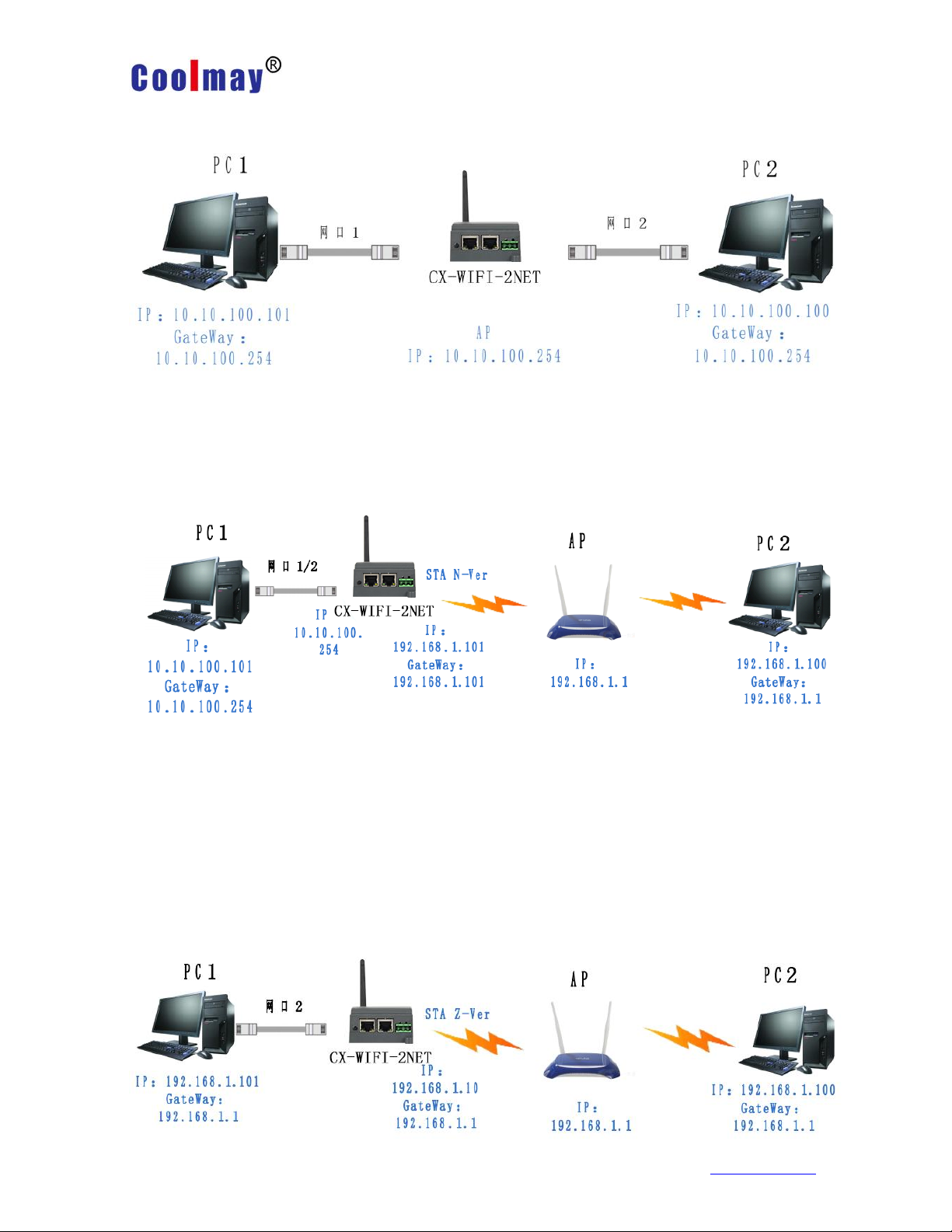
2.4.3 CX-WIFI-2NET module Ethernet interface function (STA bridge mode)
Shenzhen Coolmay Technology Co.,Ltd www.coolmay.com
Page 19
CX-WIFI-2NET module user manual
Page 19 ,Total 93 Pages
CX-WIFI-2NET Module Ethernet interface function(STA)
The CX-WIFI-2NET module acts as a STA and the module works in bridge mode.
After the module is connected to the AP, the device on the Ethernet interface obtains
the IP address from the AP (as shown in Figure 192.168.1.101). At this time, the
entire network, the module is like a transparent device, and PC1 and PC2 can
communicate with each other without any constraint. However, if the CX-WIFI-2NET
module is to communicate with other devices, you need to statically set the LAN IP
address (as shown in Figure 192.168.1.10).
2.4.4 CX-WIFI-2NET Ethernet interface function (switch)
CX-WIFI-2NET module Ethernet interface function (switch)
The CX-WIFI-2NET module acts as an AP and the module works in switch mode.
The module is connected to the AP through the network cable 2, and is connected to
the PC1 through the network port 1, so that the PC1 obtains an IP (192.168.1.101)
from the AP. In this way, PC1 and PC2 can communicate directly under a LAN.
Multiple D2 modules can be added between PC1 and AP (both work in switch mode),
so that the modules can be extended by hand, so that the coverage of the AP
network can be extended.
Note: In this mode, the module DHCP should be turned off with
AT+DHCPDEN=off, otherwise the network will be abnormal. To access the module,
you need to manually change the LAN port address of D2 to the same network
segment (192.168 above). 1.102).
2.5 WI-FI parameter settings
2.5.1 Automatic frequency selection
When the module works in STA mode, the module adjusts itself to the same
channel as the AP according to the wireless channel of the AP and accesses it.
When the module works in AP mode, it can be set to automatic frequency
selection mode, so when the module starts, it will choose a better wireless channel
according to the surrounding environment.
2.5.2 Security Mechanism
The CX-WIFI-2NET module supports multiple wireless network encryption
methods to fully guarantee the secure transmission of data, including:
WEP
WPA-PSK/TKIP
Shenzhen Coolmay Technology Co.,Ltd www.coolmay.com
Page 20
CX-WIFI-2NET module user manual
Page 20 ,Total 93 Pages
WPA-PSK/AES
WPA2-PSK/TKIP
WPA2-PSK/AES
Note: When WEP is encrypted, the HEX mode is a 10-bit or a 26-digit password,
the ASCII mode is a 5-digit or a 13-digit password, and the WPA-PSK and
WPA2-PSK passwords are at least 8 bits.
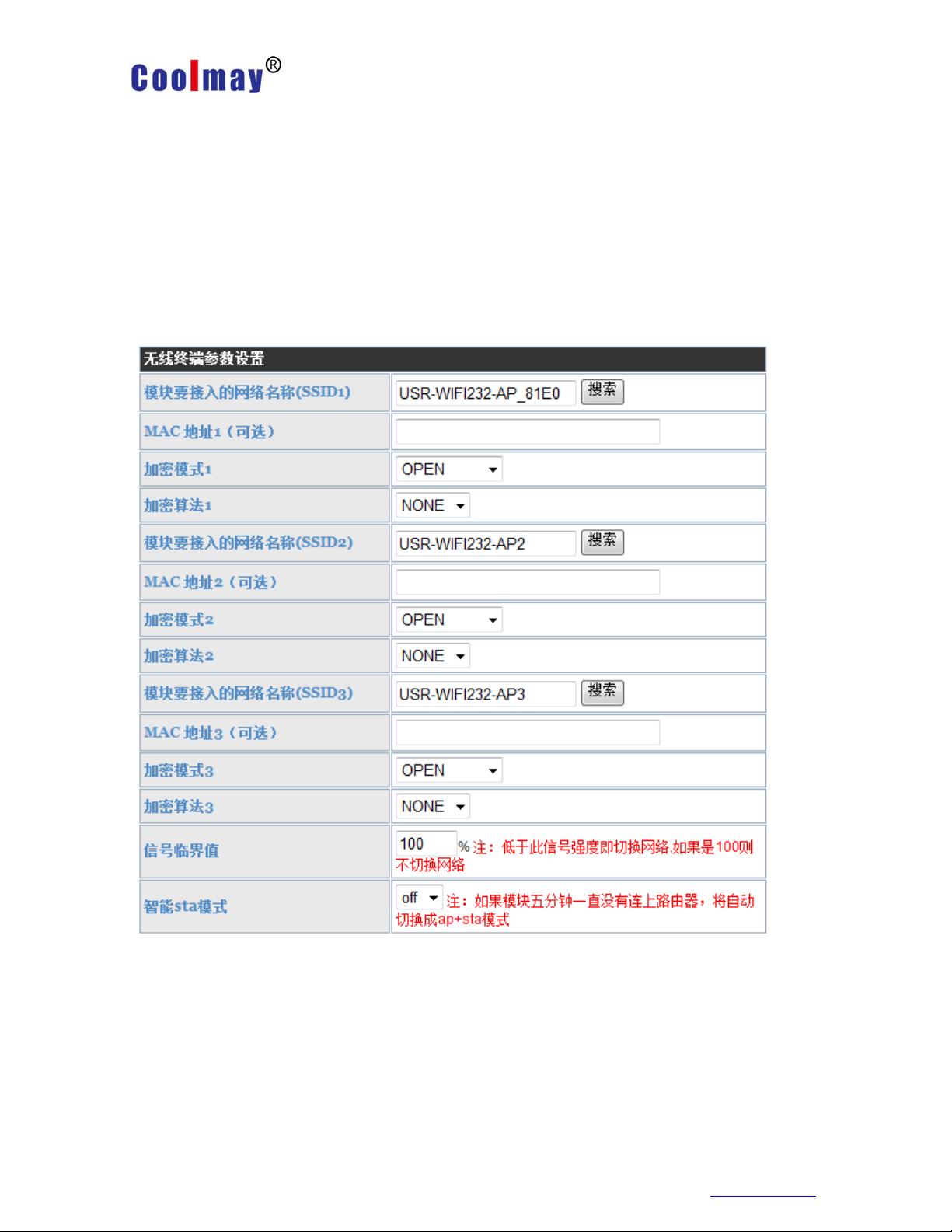
2.5.3 Add router function when STA
A "Search" button has been added to the module "Wireless Terminal Settings"
page. After clicking this button, a window will pop up showing the information of the
surrounding APs and select. As shown below:
There are three STA settings on this page. You can fill in one or fill in three. If all
three are filled in, the module will automatically switch to the next STA network if the
current network signal is less than the signal threshold (if the threshold is Filling in
100 will not automatically switch the network).
Shenzhen Coolmay Technology Co.,Ltd www.coolmay.com
Page 21
CX-WIFI-2NET module user manual
Page 21 , Total 93 pages
After selecting the router, it will return to the original page. At this time, the
encryption mode and encryption algorithm have been filled in. You only need to
Follow the prompts to write your password.
2.5.4 STA address binding function
CX-WIFI-2NET module supports the function of binding the BSSID of the
destination network during the networking process (as the STA, to connect to the
AP). According to the 802.11 protocol, different wireless networks may have the
same network name (ie, SSID/ESSID), but must correspond to a unique BSSID
address (ie, MAC address). Because the illegal intruder can connect the STAs in the
network to the illegal AP by establishing a wireless network with the same
SSID/ESSID, the network is leaked. Therefore, by binding the BSSID address, the
STA can be prevented from accessing the illegal network, thereby improving the
security of the wireless network.
2.6 Network parameter setting
CX-WIFI-2NET module has two TCP Sockets: Socket A and Socket B. The data
written to the serial port of the module will be sent to the Socket A and B
simultaneously; the data received by the module through Socket A or B will be sent
out through the serial port.
Through the different settings of the dual Socket, a variety of network
interconnection methods can be realized. Currently Sock B only supports tcp client.
2.6.1 Socket A
Socket A works in the following ways: TCP Server, TCP Client, UDP Server,
Shenzhen Coolmay Technology www.coolmay.net
Page 22
CX-WIFI-2NET module user manual
Page 22 , Total 93 pages
UDP Client. For the setting method, please refer to the AT+NETP command in the
AT command.
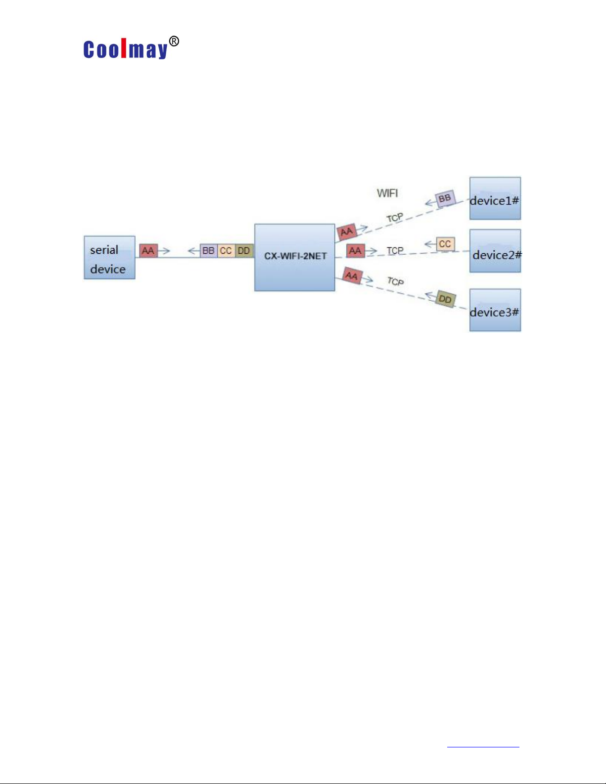
When Socket A is set to TCP Server, it can support TCP link connections of up
to 32 TCP Clients. In the multi-TCP link connection mode, data transmitted from
TCP is forwarded one by one to the serial port. The data coming from the serial port
will be copied into multiple copies and forwarded on each TCP link. The specific data
flow chart shows:
2.6.2 Socket B
The working mode of Socket B is currently only TCP Client. For the setting
method, please refer to the AT+TCPB/AT+TCPPTB/TCPADDB/TCPTOB/TCPLKB
command in the AT command.
2.7 New feature settings
2.7.1 Tcp password authentication when establishing connection
This function is only applicable when the module is used as the tcp server. When
the tcp client is connected to the module, the module will authenticate each
connected tcp.
The first data sent after tcp clien is connected should be the module's webpage
password plus carriage return. By default, the password of the module is admin, so
the first data sent by the tcp client should be "0x61 0x64 0x6D 0x69 0x6E 0x0D
0x0A" (hexadecimal). If the password is correct, the module returns "OK" and vice
versa returns "NO" and disconnects.
This feature can be turned on or disabled in "TCP Connection Password
Authentication" on the web page. Please refer to the "Web Management Page"
section for details.
2.7.2 Register ID/MAC function
This function is only applicable when the module is used as the tcp client. When
the module is connected to the server, it will have a two-byte ID number in front of
the data (the ID range is 0~65535, the high byte is first, the low byte is at After) add
two bytes of ID inversion or upload a 6-byte MAC address. For example, if the
default ID of the module is 1111 (MAC address: D8B04CF20000), the first four bytes
are sent to the server as “0x04 0x57 0xFB 0xA8” (or 0xD8 0xB0 0x4C 0xF2 0x00
Shenzhen Coolmay Technology www.coolmay.net
Page 23

Shenzhen Coolmay Technology Co.,Ltd
CX-WIFI-2NET module user manual
Page 23 , Total 93 Pages
www.coolmay.com
0x00).
There are two ways to register: one is to register your own ID/MAC when
connecting to the server for the first time; the other is to add ID/MAC in front of each
sent data.
The parameters related to this function are set on the “Serial Port and Other
Settings” section of the webpage. The ID/MAC function is built for the first time and
the ID/MAC function is disabled by default.
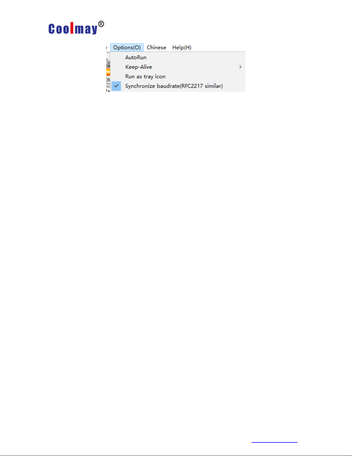
2.7.3 Adaptive baud rate function
Please use this function with our company's virtual serial port software.
In the virtual serial port software, select "synchronous baud rate (class
RFC2217)", and use the at command "AT+AABR=on" to open the module's adaptive
baud rate function and restart. As shown below:
www
Page 24
Shenzhen Coolmay Technology Co.,Ltd
CX-WIFI-2NET module user manual
Page 24 , Total 93 pages
www.coolmay.com
In the virtual serial port software, select "synchronous baud rate (class
RFC2217)", and use the at command "AT+AABR=on" to open the module's adaptive
baud rate function and restart. As shown below:
In the picture, the virtual serial port synchronizes the baud rate. The baud rate of
the module changes with the baud rate of the virtual serial port at any time, and the
module does not need to be restarted. If the module is restarted, the baud rate will
return to the previous baud rate.
2.7.4 KeepAlive Function
When the TCP connected, the keep-alive mechanism is added. Therefore,
when the network of the module is abnormal, the network abnormality can be judged
and disconnected in time. When the network is restored, the network can also be
connected to the server in time.
2.7.5 Multi-STA Function
Added multiple SAT network setting function. In STA mode, if the connected
network has a low signal, it will automatically switch to other AP networks (it will
automatically restart when switching networks).
This function provides a signal threshold that automatically switches to the
network and restarts when the current network signal is below the signal threshold. If
the signal value is set to 100, the module will not switch to networks. Even if the
current network signal is not available, it will always search the current network and
will not reconnect to other networks.
The specific settings page of this function,Please refer to section 2.5.3 chapter.
This function can also be set by the AT command, refer to section
3.2.2.2.49-3.2.2.2.55 chapters.
2.7.6 Domain name backup and smart STA
After the domain name backup function is enabled, the IP address of the
domain name will be automatically saved when the module is connected to the
server of the domain name. If the server can’t be connected over five minutes
(Including the IP address cannot be resolved or the resolved IP address cannot be
connected.) it will automatically enable the alternate IP to connect.
This function can be turned on/off in the web page or AT command (AT+IPBUP).
Smart STA function. If the module is in STA mode and has not been connected
to the router for five minutes, the module will automatically start its own AP function
and connect the router every 80 seconds at a later time. This function allows the
user to continue to control the module or set the parameters of the module wireless.
This feature is always off.
2.8 Parameter setting
Page 25

Shenzhen Coolmay Technology Co.,Ltd
CX-WIFI-2NET module user manual
Page 25 , Total 93 pages
www.coolmay.com
CX-WIFI-2NET module support web parameter settings, which can be easily set
by user using IE browser. If the module is connected to a wireless network, the PC
can be set up only if it is connected to the same wireless network. In addition, since
the CX-WIFI-2NET module is also an AP,PC can be set by being connected to the
module which needs to be set .
2.9 Firmware upgrade
The CX-WIFI-2NET module supports web online firmware upgrading.
Page 26

Shenzhen Coolmay Technology Co.,Ltd
CX-WIFI-2NET module user manual
Page 26 , Total 93 pages
www.coolmay.com
Parameter
Default setting
SSID
USR-WIFI232-AP_xxxx
IP Address
10.10.100.254
Subnet Mask
255.255.255.0
User Name
admin
Password
admin
Chapter 3 Module parameter setting
3.1 Web Management page
When using the CX-WIFI-2NET module for the first time,needs to do some
configuration of this module. You can connect AP interface of the CX-WIFI-2NET
module via PC and manage page configuration via web.
By default, the SSID of the AP interface of the CX-WIFI-2NET module is
USR-WIFI232-AP_xxxx, and the IP address and user name and password are as
follows:
CX-WIFI-2NET Module network default settings table:
3.1.1 Open management page
First connect the CX-WIFI-2NET module with the PC's wireless network card. The
SSID is USR-WIFI232-AP_xxxx. After connecting, open IE, enter web page:
http://10.10.100.254, Fill in the username and password in the pop-up dialog box,
then "confirm".
Then the web page will display the management page of the CX-WIFI-2NET module.
It supports Chinese and English language which can be selected in the upper right
corner. There are 10 pages, namely “Quick Configuration”, “Wireless Mode
Selection”, “Wireless Access Point Settings”, “Wireless Terminal Settings”, “Serial
Port and Network Settings”, “Ethernet Function Settings”, “HTTPD Client Mode”. ",
"IO Control" mode ,"advanced setting" and "module management".
Page 27
Shenzhen Coolmay Technology Co.,Ltd
CX-WIFI-2NET module user manual
Page 27 , Total 93 pages
www.coolmay.com
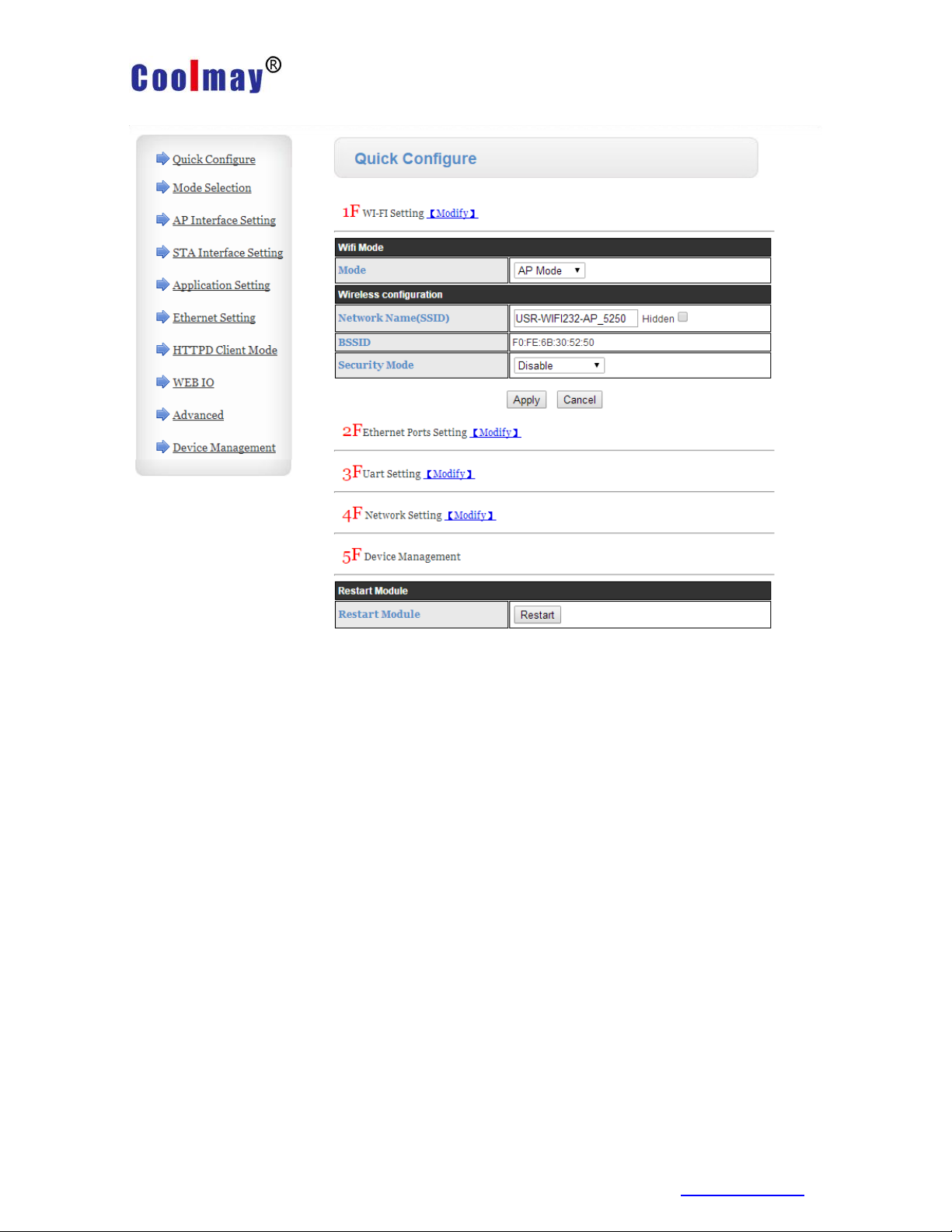
3.1.2 Quick Configuration
Quick Configuration page provides users with a quick way to configure modules.
After configuring the parameters according to the page steps and restarting the
startup module, the module can work normally, reducing the configuration steps and
time. Of course, there are fewer options on this page. If you have some detailed
configuration, needs to visit corresponding page configuration.
This page has four options to configure and a restart item. Below corresponding
instructions:
Wireless configuration: configure the wifi working mode of the module, which
can be either AP mode or STA mode;
Ethernet function configuration: open/close the Ethernet port and set the
corresponding working mode;
Serial port configuration: configure the serial port parameters of the module,
including serial port baud rate, parity bit, 485 function, etc.
Network configuration: configure the network parameters of the module, only
TCPA relevant parameters;
Restart module: After all the above parameters are configured, click Restart
Module.
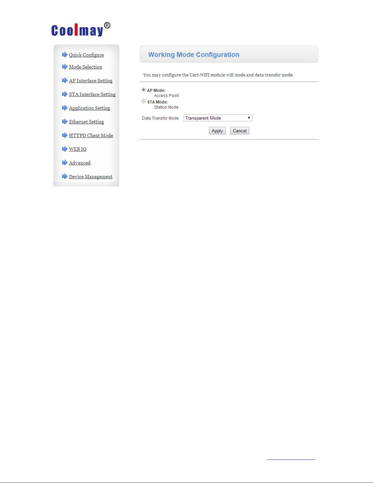
3.1.3 Wireless Mode Selection
This page can be set to select the module to work in AP mode or STA mode. The
working modes of the "Data Transfer Mode" selection module are "Transparent
Transfer Mode", "Serial Command Mode", and "HTTPD Client Mode".
Page 28
Shenzhen Coolmay Technology Co.,Ltd
CX-WIFI-2NET module user manual
Page 28 , Total 93 pages
www.coolmay.com
3.1.4 Wireless Access Point Settings
The CX-WIFI-2NET module supports the AP interface,which could be used to
manage the module conveniently, and realize self-organizing network. The
management page is as shown below. Including: SSID settings, wireless network
mode settings and wireless security settings, and the setting of the LAN composed
of APs.
Page 29

Shenzhen Coolmay Technology Co.,Ltd
CX-WIFI-2NET module user manual
Page 29 , Total 93 pages
www.coolmay.com
3.1.5 Wireless Terminal Settings
The wireless terminal interface,namely STA interface. The CX-WIFI-2NET
module can be connected to other wireless networks through the STA interface, and
settings as follows:
The page setup includes two tables, the first one is the STA's wireless settings,
including the SSID of the AP to be connected, security settings, and so on. The next
table shows the network connection mode settings, including DHCP and static
connection mode.
Page 30

Shenzhen Coolmay Technology Co.,Ltd
CX-WIFI-2NET module user manual
Page 30 , Total 93 pages
www.coolmay.com
Page 31

Shenzhen Coolmay Technology Co.,Ltd
CX-WIFI-2NET module user manual
Page 31 , Total 93 pages
www.coolmay.com
3.1.6 Serial Port and Network Settings
Application settings are settings for the wifi to uart application parameters, including:
serial port parameter settings, automatic framing settings, device id settings, and
network protocol settings.
Page 32

Shenzhen Coolmay Technology Co.,Ltd
CX-WIFI-2NET module user manual
Page 32 , Total 93 pages
www.coolmay.com
<Description>:
There are four modes on the network side: TCP Server, TCP Client, UDP server,
and UDP client.
When the module is configured as UDP server, the module remembers the last
communicated UDP client and communicates with it.While the UDP client mode only
communicates with the target IP and address. When set to TCP Server, you do not
need to enter IP address. For other settings, you need to fill in the opponent's IP
address that needs to be connected. Fill in the protocol port number at the port, and
the port numbers on both ends of the communication must be the same.
Socket B can only be TCP client to communicate with the server.
TCP connection password verification: When the module works in tcp server
mode, password verification is performed on the connected tcp client.
Note: This verification only works when the module is acting as a TCP server.
When the TCP client is connected to the TCP server of the module when it is turned
on, the first data sent to the module is the password and enter key. Password is the
one when log in to the webpage, default is “admin”. For example, the first data sent
by default should be “0x61 0x64 0x6D 0x69 0x6E 0x0D 0x0A” (hexadecimal)
3.1.7 Ethernet Function Settings
This page is used to set two Ethernet network ports of the module. Both network
Page 33

Shenzhen Coolmay Technology Co.,Ltd
CX-WIFI-2NET module user manual
Page 33 , Total 93 pages
www.coolmay.com
ports can be opened or closed. Moreover, the second network port can be set to be
used as a WAN port, so that the module can be used as a secondary router to
facilitate user networking. The specific settings page is as follows:
3.1.8 HTTPD Client Mode
This page sets the content of the HTTP protocol header in HTTPD Client mode,
including: server address, server port, request type, protocol header path, protocol
header Connection, and protocol header User-Agent.
The HTTPD Client mode supports three HTTP request methods: POST, PUT,
and GET. When the request mode is POST or PUT, the serial port data will be added
to the location behind the HTTP protocol header; when the request mode is GET, the
serial port data will be added to the protocol header path. For the specific data
transmission method, refer to section 2.2.3.
Page 34

Shenzhen Coolmay Technology Co.,Ltd
CX-WIFI-2NET module user manual
Page 34 , Total 93 pages
www.coolmay.com
3.1.9 Advanced setting
Under the advanced settings page, users can set the port mapping and DDNS
functions instead of router with less complexity. Port mapping and DDNS can be
matched to be used, In the public network environment, you can enter the peanut
shell domain name and port to find the module quickly and easily .
3.1.10 Module Management
Module management includes username/password settings, factory reset and
Page 35

Shenzhen Coolmay Technology Co.,Ltd
Page 35 , Total 93 pages
www.coolmay.com
software upgrades.
CX-WIFI-2NET module user manual
<Description>:
“Restart Module” button: When the user sets the parameters on different pages,
click “OK” to confirm.
However, these settings must take effect after the user clicks "Restart" on the
module management page. After clicking "Restart", the module will reset and restart,
and refresh the original configuration information in the memory.
3.2 Serial Port Configuration
3.2.1 Module operation mode
CX-WIFI-2NET module has two working modes,Default(start) mode actively
enters the transparent transmission mode,users can switch the module to the
command line mode via the serial port command.
The mode default UART port parameters are configured as follows: (The
HyperTerminal of the PC needs to be set accordingly)
Page 36

Shenzhen Coolmay Technology Co.,Ltd
CX-WIFI-2NET module user manual
Page 36 , Total 93 pages
www.coolmay.com
In the command line mode, the user can use the UART port to set the module
via AT+ command. Its function can completely cover the settings of the web page.
Page 37

Shenzhen Coolmay Technology Co.,Ltd
CX-WIFI-2NET module user manual
Page 37 , Total 93 pages
www.coolmay.com
3.2.1.1 Switch transparent mode to command mode
There are 2 steps from transparent mode to command mode :
Enter "+++" on the UART port, and the module will return a confirmation code
"a" after receiving "+++";
Enter the confirmation code "a" on the UART port. After receiving the
confirmation code, the module returns to "+ok" to confirm and enter the command
mode.
Pic 45 from transparent mode to command mode
<Description>:
When you enter "+++" and the confirmation code "a", the serial port is not echoed,
as above picture.
Entering "+++" and "a" needs to be completed within a certain period of time to
reduce the probability of entering the command mode by mistake during normal
operation. Specific requirements are as follows:
Enter
“+” Enter “+” Enter“+” Enter
“a”
echoed
“a”
In the command mode, the module can be set,queried and restarted by the AT+
command under the UART port.. It can also return to the transparent transmission
mode through the AT+ command. The AT+ instruction details pls refer to next section.
3.2.2 AT+ Command instruction
The AT+ command can be input directly through a serial port debugger like
HyperTerminal, or be programmed. As shown in the figure below, through the
SecureCRT tool, AT+H is a help command that lists all the commands and
instructions.
Page 38

Shenzhen Coolmay Technology Co.,Ltd
CX-WIFI-2NET module user manual
Page 38 , Total 93 pages
www.coolmay.com
The AT+ command can also be set via the USR-WIFI232-Setup software (in CD):
Click “Open Serial Port”, send “+++ a” to the left display box to reply “+OK”,
then input the AT command needs to be sent in the left operation area. After setting
well click “AT+RELD” to restart the module. The module setup is completed.
Page 39

Shenzhen Coolmay Technology Co.,Ltd
CX-WIFI-2NET module user manual
Page 39 , Total 93 pages
www.coolmay.com
Above is the AT command setting through the serial port, and the AT
command can also be set through WIFI.
First, the computer establishes a network connection with the module, using
the USR-WIFI232-Setup setting software provided on the CD.
Through the network operation, click "Search", the searched module will be
displayed, click it and set AT command on the left operation area. (same way as
the serial port setting).
3.2.2.1 Command format
AT+ command adopt ASCII-based command line, command format as below:
Format description
< >: indicates the part that must be included
[ ]: indicates an optional part
Command message
AT+<CMD>[op][para-1,para-2,para-3,para-4…]<CR>
AT+:Command message prefix
CMD:Command string
Page 40

Shenzhen Coolmay Technology Co.,Ltd
CX-WIFI-2NET module user manual
Page 40 , Total 93 pages
www.coolmay.com
[op]:Command operator, specified as parameter setting or query
“=”
:
“null”
parameter setting
:
query
[para-n]:Input when parameter setting,no need when query
<CR>: Terminator, Enter, ASCII code 0x0a or 0x0d
<Description>:
When echoing, the terminator is automatically converted to 0x0a0d. When you
enter a command, the "AT+<CMD>" character is automatically echoed to uppercase
and the parameter portion remains unchanged.
Response message
+<RSP>[op] [para-1,para-2,para-3,para-4…]<CR><LF><CR><LF>
Page 41

Shenzhen Coolmay Technology Co.,Ltd
CX-WIFI-2NET module user manual
Page 41 , Total 93 pages
www.coolmay.com
Instruction
description
(Null)
Empty instruction
E
Turn on/off echo function
ENTM
Enter transparent mode
NETP
Set / query network
protocol parameters
UART
Set / query serial port
parameters
UARTF
Turn on/off auto framing
UARTFT
Set/query automatic
framing trigger time
UARTFL
Set/query automatic
framing trigger length
TMODE
Set/Query Data Transfer
Mode (Transparent Mode
or Protocol Mode)
WMODE
Set/Query WIFI operation
mode (AP or STA)
WSKEY
Set/Query Encryption
Parameters in WIFI STA
Mode
WSSSID
Set/Query AP SSID in
WIFI STA Mode
WSLK
Query the link status in
wireless STA mode
WEBU
Set/Query the login
parameters of the WEB
page (username,
password)
WAP
Set/Query parameters in
Error code
description
-1
Invalid command format
-2
Invalid command
-3
Invalid operator
-4
Invalid parameter
-5
Operation not allowed
+:Response message prefix
RSP:response string, including:
ok:success
ERR:failure
[op]:=
[para-n]:Return parameters when querying,error when error occurs.
<CR>:ASCII code 0x0d
<LF>:ASCII code 0x0a
Error code
3.2.2.2 Instruction Set
Page 42

Shenzhen Coolmay Technology Co.,Ltd
CX-WIFI-2NET module user manual
Page 42 , Total 93 pages
www.coolmay.com
WIFI AP mode
WAKEY
Set/Query Encryption
Parameters in WIFI AP
Mode
MSLP
Set the module to enter
low power mode, turn off
WIFI
WSCAN
Search AP in STA mode
TCPLK
Query whether the TCP
link has been chained
TCPDIS
Connect/disconnect TCP
(valid only in TCP Client)
WANN
Set/query WAN settings,
only valid in STA mode
LANN
Set/Query LAN settings,
only valid in AP mode
DHCPGW
Set/Query DHCP
Gateway Address
TCPTO
Set/Query TCP Timeout
MAXSK
Set/Query Maximum TCP
Connections
TCPB
Enable/disable TCPB function
TCPPTB
Set / query the TCPB port
number
TCPADDB
Set / query the TCPB server
address
TCPTOB
Set/query TCPB timeout
TCPLKB
Query whether the TCPB
connection is built
RELD
Back to factory setting
FUDLX
Turn on/off 485 function
MMID
Set module ID
IDFIR
Turn on/off the first built-in ID
function
IDEVE
Turn on/off each data band ID
function
AABR
Turn on/off the adaptive baud
rate function
DHCPDEN
Enable/disable the DHCP
server function of the LAN port
HIDESSID
Set/Query whether to hide the
SSID of the module AP
DOMAIN
Set/query the domain name of
the login module web page
Z
Restart module
MID
Query module MID
VER
Query software version
H
Help instruction
HTTPURL
Set/Query the IP and Port of
the HTTP Server
HTTPTP
Set/Query HTTP Request
Type
Page 43

Shenzhen Coolmay Technology Co.,Ltd
CX-WIFI-2NET module user manual
Page 43 , Total 93 pages
www.coolmay.com
HTTPPH
Set/Query HTTP Protocol
Header Path
HTTPCN
Set/Query HTTP Protocol
Header Connection
HTTPUA
Set/Query HTTP Protocol
Header User-Agent
EPHYA
Turn on/off ETH interface 1
EPHYB
Turn on/off ETH interface 2
WSSSIDA
Set/Query the SSID of 1st STA
of the three STA parameter
sets
WSSSIDB
Set/Query the SSID of 2nd
STA of the three STA
parameter sets
WSSSIDC
Set/Query the SSID of 3rd
STA of the three STA
parameter sets
WSKEYA
Set/Query the encryption of
1st STA of the three STA
parameter sets
WSKEYB
Set/Query the encryption of
2nd STA of the three STA
parameter sets
WSKEYC
Set/Query the encryption of
3rd STA of the three STA
parameter sets
WSQY
Set/Query the signal switching
threshold of three STA
parameter sets
HTPMODE
New and old HTTP header
setting mode switching
(HTTPD Client)
HTPSV
Under the new version,
set/query server address
and IP (HTTPD Client)
HTPTP
Under the new version,
set/query request method
(HTTPD Client)
HTPURL
Under the new version,
set/query request path
(HTTPD Client)
HTPHEAD
Under the new version,
set/query HTTP header
(HTTPD Client)
REGEN
Set/Query Registration Type
REGTCP
Set up and query the
registration package method
REGID
Set and query the registration
package ID
IPBUP
Set up and query domain
name IP backup function
STAPRO
Set up and query smart STA
Page 44

Shenzhen Coolmay Technology Co.,Ltd
CX-WIFI-2NET module user manual
Page 44 , Total 93 pages
www.coolmay.com
features
<Description>:
The CX-WIFI-2NET module can work in AP or STA mode and set WIFI
parameters with different commands.
3.2.2.2.1 AT+E
Function: Turn on/off the echo function
Format:
AT+E<CR>
+ok<CR>< LF ><CR>< LF >
When the module switches from transparent mode to command mode, the
default echo function is turned on. After inputting AT+E for the first time, the echo
function is turned off. After inputting again, the echo function is turned on.
3.2.2.2.2 AT+ENTM
Function: Enter the transparent transmission mode:
Format:
AT+ENTM<CR>
+ok<CR>< LF ><CR>< LF >
After the command is executed correctly, the module switches from
command mode to transparent mode. If you want to enter the command mode
again, you can enter "+++" and confirm code to the command mode.
3.2.2.2.3 T+NETP
Function: Set / query network protocol parameters
Format:
Inquire:AT+NETP<CR>
+ok=<protocol,CS,port,IP><CR>< LF ><CR>< LF >
Set:AT+NETP=<protocol,CS,port,IP><CR>
+ok<CR>< LF ><CR>< LF >
Parameter:
protocol:
CS:including
TCP
UDP
SERVER: server side
CLIENT: Client
Port: Protocol port, in decimal, less than 65535
Note: When it is tcp server or udp server, the port can't be set to 80
(HTTP port), 8000 (websocket port), 49000 (usr-link)
IP: The address of the server when the module is TCP client or
UDP (you can enter the IP address of the server or the domain
name of the server).
After the module is restarted, the set parameters take effect.
3.2.2.2.4 AT+UART
Function: Set / query serial port parameters
Page 45

Shenzhen Coolmay Technology Co.,Ltd
CX-WIFI-2NET module user manual
Page 45 , Total 93 pages
www.coolmay.com
Format:
Inquire:AT+UART<CR>
+ok=<baudrate,data_bits,stop_bit,parity,flowctrl><CR>< LF ><CR>< LF >
Set:AT+UART=<baudrate,data_bits,stop_bit,parity,flowctrl><CR>
+ok<CR>< LF ><CR>< LF >
Parameter:
baudrate:baud rate,yes
300 , 600 , 1200 , 1800 , 2400 , 4800 , 9600 , 19200 , 38400 , 57600 ,
115200 ,
230400,345600,460800
data_bits:data bit,yes
5,6,7,8
stop_bits:stop bit,yes
1,2
parity:check bit, can
NONE:no check digit
EVEN:Even check
ODD:Odd check
MARK:Positive check
SPACE:Negative check
Flowctrl:Hardware Flow Control(CTSRTS)
NFC:No Hardware Flow Control
FC:Hardware flow control After the module is restarted, the
set parameters take effect.
3.2.2.2.5 AT+UARTF
Function: Turn on/off the automatic framing function
Format:
Inquire:
AT+UARTF<CR>
+ok=<para><CR>< LF ><CR>< LF >
Set:AT+ UARTF=<para ><CR>
+ok<CR>< LF ><CR>< LF >
Parameter:
para:Can take the value disable or enable,Indicates that the automatic
framing function is turned off or on.
3.2.2.2.6 AT+UARTFT
Function: set / query automatic framing trigger time
Format:
Query:
AT+UARTFT<CR>
+ok=<time><CR>< LF ><CR>< LF >
Set:AT+UARTFT=<time><CR>
+ok<CR>< LF ><CR>< LF >
Parameter:
time:Automatic framing trigger time. Unit: ms; Value range: 100~10000.
Page 46

Shenzhen Coolmay Technology Co.,Ltd
CX-WIFI-2NET module user manual
Page 46 , Total 93 pages
www.coolmay.com
3.2.2.2.7 AT+UARTFL
Function: set / query automatic framing trigger length
Format:
Query:
AT+UARTFL<CR>
+ok=<len><CR>< LF ><CR>< LF >
Set:AT+UARTFL=<len><CR>
+ok<CR>< LF ><CR>< LF >
Parameter:
Len:Automatic framing trigger length in bytes. Value range: 16~4096.
3.2.2.2.8 AT+TMODE
Function: Set / query data transmission mode (transparent mode or protocol
mode)
Format:
Query:AT+TMODE<CR>
+ok=<tmode><CR>< LF ><CR>< LF >
Set:AT+TMODE=<tmode><CR>
+ok<CR>< LF ><CR>< LF >
Parameter:
tmode:Data transfer mode, including
Through: Transparent transmission mode
Agreement: Serial Command Mode
Httpdclient: HTTPD Client mode
Modbus: Modbus TCP <=>Modbus RTU mode After the module
is restarted, the set parameters take effect.
Note: No CMD, it will not work in AT command mode by default
after power-on.
3.2.2.2.9 AT+WMODE
Function: Set/Query WIFI operation mode (AP or STA)
Format:
Query: AT+WMODE<CR>
+ok=<mode><CR>< LF ><CR>< LF >
Settings: AT+WMODE=<mode><CR>
+ok<CR>< LF ><CR>< LF >
parameter:
Mode: WIFI mode of operation, including
Page 47

Shenzhen Coolmay Technology Co.,Ltd
CX-WIFI-2NET module user manual
Page 47 , Total 93 pages
www.coolmay.com
AP: Wireless access point mode
STA: Wireless terminal mode After the module is restarted, the set parameters take
effect.
3.2.2.2.10 AT+WSKEY
Function: Set/Query Encryption Parameters in WIFI STA Mode
Format:
Query: AT+WSKEY<CR>
+ok=<auth,encry,key><CR>< LF ><CR>< LF >
Settings: AT+ WSKEY=< auth, encry, key><CR>
+ok<CR>< LF ><CR>< LF >
parameter:
Auth: authentication mode, including
OPEN
SHARED
WPAPSK
WPA2PSK
Encry: encryption algorithm, including
Valid when NONE:auth=OPEN
WEP-H: valid when auth=OPEN or SHARED (WEP, HEX)
WEP-A: valid when auth=OPEN or SHARED (WEP, ASCII)
TKIP: valid when auth= WPAPSK/WPA2PSK
Valid when AES:auth= WPAPSK/WPA2PSK
Key: password, when encry=WEP-H, the password is hexadecimal, 10 or 26 digits;
when encry=WEP-A, the password is ASCII code, 5 digits or 13 digits; otherwise it is
ASCII code, less than 64 bits, greater than 8 bits. This parameter is valid only in STA
mode. After the module is restarted, the set parameters take effect. However, these
parameters can also be set in AP mode.
Page 48

Shenzhen Coolmay Technology Co.,Ltd
CX-WIFI-2NET module user manual
Page 48 , Total 93 pages
www.coolmay.com
3.2.2.2.11 AT+WSSSID
Function: Set/Query AP SSID in WIFI STA Mode
Format:
Query: AT+WSSSID<CR>
+ok=<ap’s ssid><CR>< LF ><CR>< LF >
Settings: AT+ WSSSID=<ap’s ssid ><CR>
+ok<CR>< LF ><CR>< LF >
parameter:
Ap’s ssid: SSID of the AP
This parameter is valid only in STA mode. After the module is restarted, the
set parameters take effect. And these parameters can also be set in AP mode.
3.2.2.2.12 AT+WSLK
Function: Query the link status in wireless STA mode (only for STA mode)
Format:
Query: AT+ WSLK<CR>
+ok=<ret><CR>< LF ><CR>< LF >
parameter:
ret:
If not connected: return "Disconnected"
If there is a connection: return "AP's SSID (AP's MAC)"
If the wireless is not turned on: Return to “RF Off” This parameter is valid only in STA
mode.
3.2.2.2.13 AT+WEBU
Function: Set/Query the login parameters (user name, password) of the WEB page
Format:
Query: AT+WEBU<CR>
+ok=<usr,password><CR>< LF ><CR>< LF >
Page 49

Shenzhen Coolmay Technology Co.,Ltd
CX-WIFI-2NET module user manual
Page 49 , Total 93 pages
www.coolmay.com
Settings: AT+ WEBU=< usr,password ><CR>
+ok<CR>< LF ><CR>< LF >
parameter:
Usr: username when WEB page is accessed
Password: password for WEB page access
3.2.2.2.14 AT+WAP
Function: Set/Query parameters in WIFI AP mode Format:
Query: AT+WAP<CR>
+ok=<wifi_mode,ssid,channel><C
R>< LF ><CR>< LF >
Settings: AT+WAP=<wifi_mode, ssid,
channel><CR>
+ok<CR>< LF ><CR>< LF >
parameter:
wifi_mode:WIFI mode, including
11BG
11B
11G
11BGN
11N
ssid:SSID in AP modeD
channel:WIFI channel selection,AUTO or CH1~CH11
This parameter is valid only in AP mode. After the module is restarted, the set
parameters take effect. However, these parameters can also be set in STA mode.
3.2.2.2.15 AT+WAKEY
Function: Set/Query Encryption Parameters in WIFI AP Mode Format:
Query: AT+WAKEY<CR>
Page 50

Shenzhen Coolmay Technology Co.,Ltd
CX-WIFI-2NET module user manual
Page 50 , Total 93 pages
www.coolmay.com
+ok=<auth,encry,key><CR>< LF ><CR>< LF >
Settings: AT+ WAKEY=< auth, encry, key><CR>
+ok<CR>< LF ><CR>< LF >
parameter:
Auth: authentication mode, including
OPEN
SHARED
WPAPSK
WPA2PSK
Encry: encryption algorithm, including
Valid when NONE:auth=OPEN
WEP-H: valid when auth=OPEN or SHARED (WEP, HEX)
WEP-A: valid when auth=OPEN or SHARED (WEP, ASCII)
TKIP: valid when auth= WPAPSK/WPA2PSK
Valid when AES:auth= WPAPSK/WPA2PSK
Valid when TKIPAES:auth= WPAPSK/WPA2PSK
Key: password, when encry=WEP-H, the password is hexadecimal, 10 or 26 digits;
when encry=WEP-A, the password is ASCII, 5 digits or 13 digits; otherwise it is
ASCII code, less than 64-bit, greater than 8 bits. This parameter is valid only in AP
mode. After the module is restarted, the set parameters take effect. But it can also
be set in STA mode.
3.2.2.2.16 AT+MSLP
Function: The module enters sleep mode (when the module works in AP or STA
mode, WIFI is not available)
Format:
Query: AT+ MSLP <CR>
+ok=<sta.><CR>< LF ><CR>< LF >
Settings: AT+MSLP=<on/off><CR>
+ok<CR>< LF ><CR>< LF >
parameter:
Page 51

Shenzhen Coolmay Technology Co.,Ltd
CX-WIFI-2NET module user manual
Page 51 , Total 93 pages
www.coolmay.com
When querying, sta.: returns whether the module sleeps, such as
On, indicating no sleep
Off, indicating sleep
While setting, off puts the module into sleep mode, on allows the module to exit
sleep mode. When the module enters sleep mode, enter AT+MSLP=on and the
module exits sleep mode. Mode is still command mode.
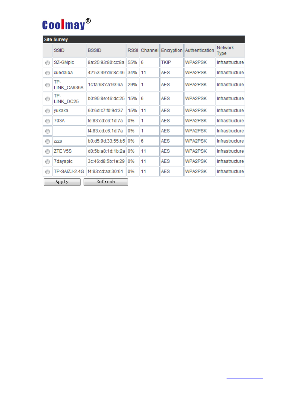
3.2.2.2.17 AT+WSCAN
Function: Search AP
Format:
AT+ WSCAN<CR>
+ok=<ap_site><CR>< LF ><CR>< LF >
parameter:
Ap_site: searched AP site
The first line of the return value is "RSSI, SSID, BSSID, Channel, Encryption,
Authentication", which are strong signals.
Degree, network name, MAC address, channel, authentication mode, encryption
algorithm.
3.2.2.2.18 AT+TCPLK
Function: Query whether the TCP connection has been chained Format:
AT+ TCPLK<CR>
+ok=<sta><CR>< LF ><CR>< LF >
Parameters:
sta.: Returns whether TCP builds a chain, such as
on, indicating that the chain has been built
off, indicating that there is no chain built.
3.2.2.2.19 AT+TCPDIS
Function: Link/Disconnect TCP (valid only in TCP Client)
Page 52

Shenzhen Coolmay Technology Co.,Ltd
CX-WIFI-2NET module user manual
Page 52 , Total 93 pages
www.coolmay.com
Format:
Query: AT+ TCPDIS <CR>
+ok=<sta.><CR>< LF ><CR>< LF >
Settings: AT+TCPDIS=<on/off><CR>
+ok<CR>< LF ><CR>< LF >
parameter:
When querying, sta.: Returns whether the TCP Client is linkable, such as
On, expressed as linkable status
Off, indicating that it is not linkable
While setting, the off setting module is unlinkable, that is, after the command is
finished, the module immediately disconnects and no longer reconnects.
On: Sets the module to be linkable, that is, after the command is completed, the
module immediately begins to reconnect to the server.
3.2.2.2.20 AT+WANN
Function: Set/query WAN settings, only valid in STA mode
Format:
Query: AT+WANN<CR>
+ok=<mode,address,mask,gateway><CR>< LF ><CR>< LF >
Settings: AT+ WANN=< mode,address,mask,gateway ><CR>
+ok<CR>< LF ><CR>< LF >
parameter:
mode:WAN port IP mode, such as
Static, static IP
DHCP, dynamic IP
address.:WAN IP address
mask:WAN port subnet mask
gateway:WAN port gateway address
Page 53

Shenzhen Coolmay Technology Co.,Ltd
CX-WIFI-2NET module user manual
Page 53 , Total 93 pages
www.coolmay.com
3.2.2.2.21 AT+LANN
Function: Set / query LAN settings, only valid in
AP mode
Format:
Query: AT+LANN<CR>
+ok=<address,mask ><CR>< LF ><CR>< LF >
Settings: AT+ LANN=<address,mask ><CR>
+ok<CR>< LF ><CR>< LF >
parameter:
Address.:LAN port IP address
Mask: LAN port subnet mask
Note: The wan port address of the module viewed by WANN and the lan port
address of the module viewed by LANN cannot be set to be as the same network
segment. Otherwise, the module does not work properly.
3.2.2.2.22 AT+DHCPGW
Function: Set/Query DHCP
Gateway Address
Format:
Query: AT+DHCPGW<CR>
+ok=<address><CR><
LF ><CR>< LF >
Settings: AT+
DHCPGW=<address ><CR>
+ok<CR>< LF ><CR>< LF >
parameter:
Address.:DHCP gateway
address
Page 54

Shenzhen Coolmay Technology Co.,Ltd
CX-WIFI-2NET module user manual
Page 54 , Total 93 pages
www.coolmay.com
3.2.2.2.23 AT+TCPTO
Function: Set/Query TCP Timeout
Format:
Query: AT+TCPTO<CR>
+ok=<time><CR>< LF ><CR>< LF >
Settings: AT+ TCPTO=<time ><CR>
+ok<CR>< LF ><CR>< LF >
parameter:
Time.: TCP timeout, <= 600 (600 seconds), >=0 (0 means no timeout), default is 0
TCP timeout: The module TCP channel does not receive any data to start counting,
and clears the count when it receives data. If the timing is longer than the TCPTO
time, disconnect. When the module works in the TCP Client, it will reconnect to the
TCP Server. When the module is a TCP server, the TCP client needs to reconnect
actively.
3.2.2.2.24 AT+MAXSK
Function: Set/Query Maximum TCP Connections Format:
Query: AT+MAXSK<CR>
+ok=<num><CR>< LF ><CR>< LF >
Settings: AT+ MAXSK =<num ><CR>
+ok<CR>< LF ><CR>< LF >
parameter:
Num: Maximum number of TCP connections, which can support 1 to 32. The
default is 32.
When set to TCP Server, the module can support up to 32 TCP connections. If users
do not need so many connections, you can set this parameter to be appropriately
reduced.
3.2.2.2.25 AT+TCPB
Function: Enable/disable TCPB function Format:
Page 55

Shenzhen Coolmay Technology Co.,Ltd
CX-WIFI-2NET module user manual
Page 55 , Total 93 pages
www.coolmay.com
Query: AT+TCPB <CR>
+ok=<sta.><CR>< LF ><CR>< LF >
Settings: AT+TCPB=<on/off><CR>
+ok<CR>< LF ><CR>< LF >
parameter:
When querying, sta.: Returns whether the TCPB function is enabled, such as
On, indicating TCPB enable
Off, indicating that TCPB is not enabled. After the module is restarted, the set
parameters take effect.
3.2.2.2.26 AT+TCPPTB
Function: Set/Query the port number of TCPB Format:
Query: AT+TCPPTB <CR>
+ok=<port><CR>< LF ><CR>< LF >
Settings: AT+TCPPTB=<port><CR>
+ok<CR>< LF ><CR>< LF >
parameter:
Port: Protocol port, in decimal, less than 65535
After the module is restarted, the set parameters take effect.
3.2.2.2.27 AT+TCPADDB
Function: Set/Query TCPB Server Format:
Query: AT+TCPADDB <CR>
+ok=<add><CR>< LF ><CR>< LF >
Settings: AT+TCPADDB=<add><CR>
+ok<CR>< LF ><CR>< LF >
parameter:
Add: TCPB server address (you can enter the server's IP address, or the server
domain name). After the module is restarted, the set parameters take effect.
Page 56

Shenzhen Coolmay Technology Co.,Ltd
CX-WIFI-2NET module user manual
Page 56 , Total 93 pages
www.coolmay.com
3.2.2.2.28 AT+TCPTOB
Function: Set/Query TCPB Timeout Time
Format:
Query: AT+TCPTOB<CR>
+ok=<time><CR>< LF ><CR>< LF >
Settings: AT+ TCPTOB=<time ><CR>
+ok<CR>< LF ><CR>< LF >
parameter:
Time.: TCPB timeout, <= 600 (600 seconds), >=0 (0 means no timeout), default is
0
3.2.2.2.29 AT+TCPLKB
Function: Query whether the TCPB link has been built. Format:
AT+ TCPLKB<CR>
+ok=<sta><CR>< LF ><CR>< LF >
parameter:
Sta.: Returns whether TCPB builds a chain, such as
On, indicating that the chain has been built
Off, indicating that there is no chain
3.2.2.2.30 AT+FUDLX
Function: RS485 open and close command
Format:
AT+FUDLX=on/off<CR>
+ok<CR>< LF ><CR>< LF >
This command enables or disables the 485 control function. The default RS485 is off
and the 485 control pin is RTS. The factory settings are valid after this command is
set.
Page 57

Shenzhen Coolmay Technology Co.,Ltd
CX-WIFI-2NET module user manual
Page 57 , Total 93 pages
www.coolmay.com
3.2.2.2.31 AT+MMID
Function: Set module ID command
Format:
AT+MMID=<ID><CR>
+ok=<ID><CR>< LF ><CR>< LF >
parameter:
ID: The value of the ID, ranging from 0 to 65535.
3.2.2.2.32 AT+IDFIR
Function: First built with ID function to turn off the command format:
AT+IDFIR=on/off<CR>
+ok<CR>< LF ><CR>< LF >
This command enables or disables the first built-in ID function. The default is off.
3.2.2.2.33 AT+IDEVE
Function: Each data with ID function turns on the off command format:
AT+IDEVE=on/off<CR>
+ok<CR>< LF ><CR>< LF >
This command enables or disables the data ID function each time. The default is off.
Note: The function of the ID requires the server to handle it accordingly. When the
module is connected to the server, it will have a two-byte ID number in front of the
data (ID range is 0~65535, high byte first, low byte later) plus two bytes of ID inverse.
For example, if the default ID of the module is 1111, the first four bytes are sent to
the server as "0x04 0x57 0xFB 0xA8".
3.2.2.2.34 AT+AABR
Function: adaptive baud rate function on and off command
Format:
Page 58

Shenzhen Coolmay Technology Co.,Ltd
CX-WIFI-2NET module user manual
Page 58 , Total 93 pages
www.coolmay.com
AT+AABR=on/off<CR>
+ok<CR>< LF ><CR>< LF >
This command enables or disables the adaptive baud rate function, which is enabled
by default.
3.2.2.2.35 AT+DHCPDEN
Function: Enable/disable DHCP server function of LAN port
Format:
AT+DHCPDEN=on/off<ID><CR>
+ok=<ID><CR>< LF ><CR>< LF >
parameter:
This command enables or disables the DHCP server function of the LAN port. The
default is enabled.
3.2.2.2.36 AT+HIDESSID
Function: Turn on/off to hide the SSID of the module AP
Format:
AT+HIDESSID=on/off<CR>
+ok<CR>< LF ><CR>< LF >
This command enables or disables the hiding of the SSID of the module AP. The
default is off.
3.2.2.2.37 AT+DOMAIN
Function: Set/Query the domain name of the login module webpage Format:
Query: AT+DOMAIN<CR>
+ok=<name><CR>< LF ><CR>< LF >
Settings: AT+ DOMAIN=<name ><CR>
+ok<CR>< LF ><CR>< LF >
parameter:
Name: The domain name of the login module web page.
Page 59

Shenzhen Coolmay Technology Co.,Ltd
CX-WIFI-2NET module user manual
Page 59 , Total 93 pages
www.coolmay.com
3.2.2.2.38 AT+RELD
Function: Restore factory settings
Format:
AT+ RELD<CR>
+ok=rebooting...<CR>< LF ><CR>< LF >
This command restores the factory settings of the module and then automatically
restarts.
3.2.2.2.39 AT+Z
Function: restart the module
Format:
AT+ Z<CR>
Module restart
3.2.2.2.40 AT+MID
Function: Query module MID
Format:
Query: AT+MID<CR>
+ok=<module_id><CR>< LF ><CR>< LF >
parameter:
Module_id: module MID, format
A11-yymmddnnnn
yymmdd: indicates the date of manufacture, year, month and day respectively
nnnn: indicates the production serial number
3.2.2.2.41 AT+VER
Function: Query software version
format:
Query: AT+VER<CR>
+ok=<ver><CR>< LF ><CR>< LF >
parameter:
Ver: return module software version
Page 60

Shenzhen Coolmay Technology Co.,Ltd
CX-WIFI-2NET module user manual
Page 60 , Total 93 pages
www.coolmay.com
3.2.2.2.42 AT+H
Function: help instructions
format:
Query: AT+H<CR>
+ok=<commod help><CR>< LF ><CR>< LF >
Parameters: commod help: command line description
3.2.2.2.43 AT+HTTPURL
Function: Set/Query IP and Port Format of HTTP Server:
Query: AT+HTTPURL<CR>
+ok=<ip>,<port><CR>< LF ><CR>< LF >
Settings: AT+HTTPURL=<ip>,<port><CR>
+ok<CR>< LF ><CR>< LF >
parameter:
Ip: ip of the HTTP server.
port:Port of the HTTP server.
3.2.2.2.44 AT+HTTPTP
Function: Set/Query HTTP
Request Type Format:
Query: AT+ HTTPTP<CR>
+ok=<Type><CR><
LF ><CR>< LF >
Settings:
AT+HTTPTP=<Type><CR>
+ok<CR>< LF ><CR><
LF >
parameter:
Type: HTTP request type,
such as
GET
PUT
Page 61

Shenzhen Coolmay Technology Co.,Ltd
CX-WIFI-2NET module user manual
Page 61 , Total 93 pages
www.coolmay.com
POST
3.2.2.2.45 AT+HTTPPH
Function: Set/Query HTTP
Protocol Header Path Format:
Query: AT+HTTPPH<CR>
+ok=<path><CR>< LF ><CR>< LF >
Settings: AT+HTTPPH=<path><CR>
+ok<CR>< LF ><CR>< LF >
parameter:
Path: The protocol header path of HTTP.
3.2.2.2.46 AT+HTTPCN
Function: Set/Query Connection of HTTP Protocol Header
format:
Query: AT+HTTPCN<CR>
+ok=<Connection><CR>< LF ><CR>< LF >
Settings: AT+HTTPCN=<Connection><CR>
+ok<CR>< LF ><CR>< LF >
parameter:
Connection: The Connection of the HTTP protocol header.
3.2.2.2.47 AT+HTTPUA
Function: Set/Query User-Agent of HTTP Protocol Header
Format:
Query: AT+HTTPUA<CR>
+ok=<User-Agent><CR>< LF ><CR>< LF >
Settings: AT+HTTPUA=<User-Agent><CR>
Page 62

Shenzhen Coolmay Technology Co.,Ltd
CX-WIFI-2NET module user manual
Page 62 , Total 93 pages
www.coolmay.com
+ok<CR>< LF ><CR>< LF >
parameter:
User-Agent: User-Agent of the HTTP protocol header.
3.2.2.2.48 AT+EPHYA
Function: Turn on/off Ethernet 1 function Format:
AT+EPHYA=on/off<ID><CR>
+ok=<ID><CR>< LF ><CR>< LF >
parameter:
This command enables or disables the Ethernet 1 function, which is enabled by
default.
3.2.2.2.49 AT+EPHYB
Function: Enable/disable Ethernet 2 function
Format:
AT+EPHYB=on/off<ID><CR>
+ok=<ID><CR>< LF ><CR>< LF >
parameter:
This command enables or disables the Ethernet 2 function, which is enabled by
default.
With AT+FVEW=disable/enable, you can set the module network port to work in lan
(disable) or wan.
(enable), the instruction restores the factory settings to take effect.
3.2.2.2.50 AT+WSSSIDA
Function: Set/Query the first AP SSID under the three STA parameter sets of
WIFI
Format:
Query: AT+WSSSIDA<CR>
Page 63

Shenzhen Coolmay Technology Co.,Ltd
CX-WIFI-2NET module user manual
Page 63 , Total 93 pages
www.coolmay.com
+ok=<ap’s ssid><CR>< LF ><CR>< LF >
Settings: AT+ WSSSIDA=<ap’s ssid ><CR>
+ok<CR>< LF ><CR>< LF >
parameter:
Ap’s ssid: SSID of the AP
This parameter is valid only in STA mode. After the module is restarted, the
set parameters take effect. However, these parameters can also be set in
AP mode.
3.2.2.2.51 AT+WSSSIDB
Function: Set/Query the second AP SSID under the WIF three STA
parameter sets.
Format:
Query: AT+WSSSIDB<CR>
+ok=<ap’s ssid><CR>< LF ><CR>< LF >
Settings: AT+ WSSSIDB=<ap’s ssid ><CR>
+ok<CR>< LF ><CR>< LF >
parameter:
Ap’s ssid: SSID of the AP
This parameter is valid only in STA mode. After the module is restarted, the
set parameters take effect. However, these parameters can also be set in
AP mode.
3.2.2.2.52 AT+WSSSIDC
Function: Set/Query the third AP SSID under the three STA parameter sets
of WIFI
Format:
Query: AT+WSSSIDC<CR>
+ok=<ap’s ssid><CR>< LF ><CR>< LF >
Settings: AT+ WSSSIDC=<ap’s ssid ><CR>
Page 64

Shenzhen Coolmay Technology Co.,Ltd
CX-WIFI-2NET module user manual
Page 64 , Total 93 pages
www.coolmay.com
+ok<CR>< LF ><CR>< LF >
parameter:
Ap’s ssid: SSID of the AP
This parameter is valid only in STA mode. After the module is restarted, the
set parameters take effect. However, these parameters can also be set in
AP mode.
3.2.2.2.53 AT+WSKEYA
Function: Set/Query the first AP encryption under the three STA parameter sets of
WIFI
Format:
Query: AT+WSKEYA<CR>
+ok=<auth,encry,key><CR>< LF ><CR>< LF >
Settings: AT+ WSKEYA=< auth, encry, key><CR>
+ok<CR>< LF ><CR>< LF >
parameter:
Auth: authentication mode, including
OPEN
SHARED
WPAPSK
WPA2PSK
Encry: encryption algorithm, including
Valid when NONE:auth=OPEN
WEP-H: valid when auth=OPEN or SHARED (WEP, HEX)
WEP-A: valid when auth=OPEN or SHARED (WEP, ASCII)
TKIP: valid when auth= WPAPSK/WPA2PSK
Valid when AES:auth= WPAPSK/WPA2PSK
Key: password, when encry=WEP-H, the password is hexadecimal, 10 or 26 digits;
when encry=WEP-A, the password is ASCII, 5 digits or 13 digits; otherwise it is
ASCII code, less than 64-bit, greater than 8 bits. This parameter is valid only in STA
mode. After the module is restarted, the set parameters take effect. But it can also
be set in AP mode.
Page 65

Shenzhen Coolmay Technology Co.,Ltd
CX-WIFI-2NET module user manual
Page 65 , Total 93 pages
www.coolmay.com
3.2.2.2.54 AT+WSKEYB
Function: Set/Query WIFI Three AP encryption under three STA parameter sets
format:
Query: AT+WSKEYB<CR>
+ok=<auth,encry,key><CR>< LF ><CR>< LF >
Settings: AT+ WSKEYB=< auth, encry, key><CR>
+ok<CR>< LF ><CR>< LF >
parameter:
Auth: authentication mode, including
OPEN
SHARED
WPAPSK
WPA2PSK
Encry: encryption algorithm, including
Valid when NONE:auth=OPEN
WEP-H: valid when auth=OPEN or SHARED (WEP, HEX)
WEP-A: valid when auth=OPEN or SHARED (WEP, ASCII)
TKIP: valid when auth= WPAPSK/WPA2PSK
Valid when AES:auth= WPAPSK/WPA2PSK
Key: password, when encry=WEP-H, the password is hexadecimal, 10 or 26 digits;
when encry=WEP-A, the password is ASCII, 5 digits or 13 digits; otherwise it is
ASCII code, less than 64-bit, greater than 8 bits. This parameter is valid only in STA
mode. After the module is restarted, the set parameters take effect. But it can also
be set in AP mode.
3.2.2.2.55 AT+WSKEYC
Function: Set/Query WIFI Three AP encryption under three STA parameter sets
Format:
Query: AT+WSKEYC<CR>
Page 66

Shenzhen Coolmay Technology Co.,Ltd
CX-WIFI-2NET module user manual
Page 66 , Total 93 pages
www.coolmay.com
+ok=<auth,encry,key><CR>< LF ><CR>< LF >
Settings: AT+ WSKEYC=< auth, encry, key><CR>
+ok<CR>< LF ><CR>< LF >
parameter:
Auth: authentication mode, including
OPEN
SHARED
WPAPSK
WPA2PSK
Encry: encryption algorithm, including
Valid when NONE:auth=OPEN
WEP-H: valid when auth=OPEN or SHARED (WEP, HEX)
WEP-A: valid when auth=OPEN or SHARED (WEP, ASCII)
TKIP: valid when auth= WPAPSK/WPA2PSK
Valid when AES:auth= WPAPSK/WPA2PSK
Key: password, when encry=WEP-H, the password is hexadecimal, 10 or 26 digits;
when encry=WEP-A, the password is ASCII, 5 digits or 13 digits; otherwise it is
ASCII code, less than 64-bit, greater than 8 bits. This parameter is valid only in STA
mode. After the module is restarted, the set parameters take effect. But it can also
be set in AP mode.
These parameters.
3.2.2.2.56 AT+WSQY
Function: Set/Query the signal threshold (percentage) of the three STA parameter
sets
format:
Query: AT+WSQY<CR>
+ok=<ret><CR>< LF ><CR>< LF >
Settings: AT+ WSQY=< ret><CR>
+ok<CR>< LF ><CR>< LF >
parameter:
ret:
Page 67

Shenzhen Coolmay Technology Co.,Ltd
CX-WIFI-2NET module user manual
Page 67 , Total 93 pages
www.coolmay.com
The percentage of signal strength, such as the signal strength is 50%, should be
set to AT+WSQY=50<CR>
Note: If set to 100, the module will not automatically switch the WIFI network. If the
customer uses only one STA parameter, be sure to set this parameter to 100.
3.2.2.2.57 AT+HTPMODE
Function: New and old HTTP header setting mode switching (HTTPD Client)
Format:
Query: AT+HTPMODE<CR>
+ok=<type><CR>< LF ><CR>< LF >
Settings: AT+HTPMODE=<type><CR>
+ok<CR>< LF ><CR>< LF >
parameter:
Type: authentication mode, including
New : new HTTP header settings
Old: Older HTTP header settings
This parameter is valid only in HTTPD Client mode. After the module is restarted,
the set parameters take effect. However, this parameter can also be set in other
modes.
3.2.2.2.58 AT+HTPSV
Function: Set/Query IP and Port of HTTP Server
format:
Query: AT+ HTPSV<CR>
+ok=<ip>,<port><CR>< LF ><CR>< LF >
Settings: AT+ HTPSV=<ip>,<port><CR>
+ok<CR>< LF ><CR>< LF >
parameter:
Ip: ip of the HTTP server.
Port: The port of the HTTP server.
Page 68

Shenzhen Coolmay Technology Co.,Ltd
CX-WIFI-2NET module user manual
Page 68 , Total 93 pages
www.coolmay.com
This parameter is valid only in HTTPD Client mode. After the module is restarted,
the set parameters take effect. However, these parameters can also be set in other
modes.
3.2.2.2.59 AT+HTPTP
Function: Set/Query HTTP Request Type
Format:
Query: AT+HTPTP<CR>
+ok=<Type><CR>< LF ><CR>< LF >
Settings: AT+HTPTP=<Type><CR>
+ok<CR>< LF ><CR>< LF >
parameter:
Type: HTTP request type, such as
GET
PUT
POST
This parameter is valid only in HTTPD Client mode. After the module is restarted,
the set parameters take effect. However, these parameters can also be set in other
modes.
3.2.2.2.60 AT+HTPURL
Function: Set/Query HTTP Protocol Header Path Format:
Query: AT+HTPURL<CR>
+ok=<path><CR>< LF ><CR>< LF >
Settings: AT+HTPURL=<path><CR>
+ok<CR>< LF ><CR>< LF >
parameter:
Path: The request path for HTTP.
Page 69

Shenzhen Coolmay Technology Co.,Ltd
CX-WIFI-2NET module user manual
Page 69 , Total 93 pages
www.coolmay.com
3.2.2.2.61 AT+HTPHEAD
Function: Set/Query HTTP Header Content Format:
Query: AT+HTPHEAD<CR>
+ok=<head><CR>< LF ><CR>< LF >
Settings: AT+HTPHEAD=<head><CR>
+ok<CR>< LF ><CR>< LF >
parameter:
Head: The header content of HTTP. The carriage return line feed in the header
content should be replaced with the string "<<CRLF>>", the longest
200 bytes.
Note: AT commands such as AT+HTPMODE, AT+HTPSV, AT+HTPTP, AT+HTPURL,
and AT+HTPHEAD are supported in V5.01D.14 and above.
3.2.2.2.62 AT+REGEN
Function: Set/Query Registration Package Type Format:
Query: AT+REGEN<CR>
+ok=<mode><CR>< LF ><CR>< LF >
Settings: AT+REGEN=<mode><CR>
+ok<CR>< LF ><CR>< LF >
parameter:
Mode: the type of the registration package, such as
Id: the registration package is an ID
Mac: The registration package is a MAC address.
Off: Do not open the registration package function
3.2.2.2.63 AT+REGTCP
Function: Set/Query Registration Method Format:
Query: AT+REGTCP<CR>
+ok=<type><CR>< LF ><CR>< LF >
Settings: AT+REGTCP=<type><CR>
+ok<CR>< LF ><CR>< LF >
Page 70

Shenzhen Coolmay Technology Co.,Ltd
CX-WIFI-2NET module user manual
Page 70 , Total 93 pages
www.coolmay.com
parameter:
Type: the type of registration package, such as
First: the registration package is sent when the module establishes a connection.
Every: send a registration package each time data is sent
3.2.2.2.64 AT+REGID
Function: Set/Query Registration Package ID
Format:
Query: AT+REGID<CR>
+ok=<ID><CR>< LF ><CR>< LF >
Settings: AT+REGID=<ID><CR>
+ok<CR>< LF ><CR>< LF >
parameter:
ID: The value of the ID, ranging from 0 to 65535.
3.2.2.2.65 AT+IPBUP
Function: Enable/disable domain name resolution IP backup function Format:
Query: AT+IPBUP<CR>
+ok=<backup-a,backup-b><CR>< LF ><CR>< LF >
Settings: AT+ IPBUP=< backup-a, backup-b><CR>
+ok<CR>< LF ><CR>< LF >
parameter:
Backup-a: authentication mode, including
On: Open TCPA domain name resolution IP backup function
Off: Disable TCPA domain name resolution IP backup function
Backup-b: encryption algorithm, including
On: Open TCPB domain name resolution IP backup function
Off: Disable TCPB domain name resolution IP backup function This command
enables or disables the on/off domain name resolution IP backup function. The
default is off.
Page 71

Shenzhen Coolmay Technology Co.,Ltd
CX-WIFI-2NET module user manual
Page 71 , Total 93 pages
www.coolmay.com
3.2.2.2.66 AT+STAPRO
Function: Turn on/off the smart STA function Format:
Query: AT+STAPRO<CR>
+ok=<mode><CR>< LF ><CR>< LF >
Settings: AT+ STAPRO=< mode><CR>
+ok<CR>< LF ><CR>< LF >
parameter:
Mode: Included
On: Turn on the smart sta function
Off: Turn off the smart sta function This command is off by default.
Page 72

Shenzhen Coolmay Technology Co.,Ltd
CX-WIFI-2NET module user manual
www.coolmay.com
Page 72 , Total 93 pages
3.3 AP Mode Setting Procedure
Step 1: Configure CX-WIFI-2NET module communication
① Turn on your computer's wireless network and search for the wireless
signal USR-WIFI232-AP_**** to connect to the wireless network.
② Open a browser, enter the URL "http://10.10.100.254" and press Enter.
Fill in the user name and password in the pop-up dialog box. The default
username is admin, the password defaults to admin, and then click OK.
③ Enter the quick configuration, the working mode in the wireless mode
is selected as the AP mode, the network name (SSID) user can change it by
itself, that is, the WiFi name, the encryption mode can set the password of the
WiFi, the Disable means no password, the wireless access point security
setting as WPA2-PSK, select the AES for the WPA encryption algorithm, set
the password by yourself, and click OK:
Page 73

Shenzhen Coolmay Technology Co.,Ltd
CX-WIFI-2NET module user manual
www.coolmay.com
Page 73 , Total 93 pages
Page 74

Shenzhen Coolmay Technology Co.,Ltd
CX-WIFI-2NET module user manual
www.coolmay.com
Page 74 , Total 93 pages
④ In the serial port configuration, the working mode uses the default
transparent transmission mode. In the serial port parameter configuration, the
baud rate: 9600, data bit: 7, check digit: EVEN, stop bit: 1, (Note: 9600 7 EVEN
1 is Coolmay PLC Or compatible with the Mitsubishi protocol PLC parameters,
the specific baud rate, data bits, check bits, stop bits are based on the default
parameters of the connected PLC or serial device), other parameters as
default, and then click OK:
⑤ In the network mode, the network mode is set as Server, the protocol is
set as TCP, the port is set as 8899, other parameters are as default, and then
click OK. After all the above steps are set, click Restart in the restart module:
Page 75

Shenzhen Coolmay Technology Co.,Ltd
CX-WIFI-2NET module user manual
www.coolmay.com
Page 75 , Total 93 pages
Page 76

Shenzhen Coolmay Technology Co.,Ltd
CX-WIFI-2NET module user manual
www.coolmay.com
Page 76 , Total 93 pages
Step 2: Configure the virtual serial port software
① Open the computer's wireless network and search for the wireless
signal USR-WIFI232-AP_**** to connect to the wireless network:
② Add a virtual serial port:
③ Connect the virtual serial port and change the sync baud rate option in
the option to unchecked:
Page 77

Shenzhen Coolmay Technology Co.,Ltd
CX-WIFI-2NET module user manual
www.coolmay.com
Page 77 , Total 93 pages
④ The virtual serial port has been established, and the serial port number is
the virtual serial port COM2. At this time, the PLC programming software can
be connected by COM2, and the PLC download program and wireless
monitoring can be performed. Note: The PLC software version must be GX
8.52 or WORKS 2.
3.4 STA mode setting procedure
The first step: configure CX-WIFI-2NET module communication
① Open the computer's wireless network and search for the wireless
signal USR-WIFI232-AP_**** to connect to the wireless network:
Page 78

Shenzhen Coolmay Technology Co.,Ltd
CX-WIFI-2NET module user manual
www.coolmay.com
Page 78 , Total 93 pages
② Open a browser, enter the URL "http://10.10.100.254" and press Enter.
Fill in the user name and password in the pop-up dialog box. The default
username is admin, the password defaults to admin, and then determine:
③ Enter the quick configuration, select the STA mode in the wireless mode,
click Search, and search for the network name (SSID) to be accessed by the
module.
Page 79

Shenzhen Coolmay Technology Co.,Ltd
CX-WIFI-2NET module user manual
www.coolmay.com
Page 79 , Total 93 pages
In this screenshot, the xi777 wireless network is connected and the correct
password is entered. (Note that the specific network and password to be
connected need to be set on site, this screenshot is for reference only), other
parameters are default, then click to confirm:
Page 80

Shenzhen Coolmay Technology Co.,Ltd
CX-WIFI-2NET module user manual
www.coolmay.com
Page 80 , Total 93 pages
④ In the serial port configuration, the working mode uses the default
transparent transmission mode. In the serial port parameter configuration, the
baud rate: 9600, data bit: 7, check digit: EVEN, stop bit: 1, (note: 9600 7 EVEN
1 is Gu Mei PLC or PLC parameters compatible with Mitsubishi protocol, the
specific baud rate, data bit, check digit, stop bit are set according to the default
parameters of the connected PLC or serial device), other parameters are
default, then click OK:
Page 81

Shenzhen Coolmay Technology Co.,Ltd
CX-WIFI-2NET module user manual
www.coolmay.com
Page 81 , Total 93 pages
⑤ In network mode, the network mode is set to Client, the protocol is set to
TCP, the port is set to 25565, the server address is set to 120.76.116.193,
other parameters are default, and then click OK:
Page 82

Shenzhen Coolmay Technology Co.,Ltd
CX-WIFI-2NET module user manual
www.coolmay.com
Page 82 , Total 93 pages
⑥ Enter the serial port and network settings, device registration package
settings, the registration package type is changed to upload ID, the registration
package mode is selected First, the device ID is set to 64847 in this
screenshot, (Note: each CX-WIFI-2NET module needs to use STA Mode, need
device ID, you need to consult Gumei technical customer service to request
and then set), then click OK:
Page 83

Shenzhen Coolmay Technology Co.,Ltd
CX-WIFI-2NET module user manual
www.coolmay.com
Page 83 , Total 93 pages
⑦ After all the above steps are set, enter the module management and
click Restart in the restart module:
Page 84

Shenzhen Coolmay Technology Co.,Ltd
CX-WIFI-2NET module user manual
www.coolmay.com
Page 84 , Total 93 pages
Page 85

Shenzhen Coolmay Technology Co.,Ltd
CX-WIFI-2NET module user manual
www.coolmay.com
Page 85 , Total 93 pages
Step 2: Configure the virtual serial port software
① Add virtual serial port:
Note:
The virtual serial port is set to an unoccupied COM port on the computer;
Network protocol selects TCP Client;
Target IP/domain name setting 120.76.116.193 (Note: The target
IP/domain name is Shenzhen Coolmay Technology domain name, which
must be connected with Coolmay server);
Target port setting 25565;
Registration ID setting in Advanced 43589(Note: Each CX-WIFI-2NET
module has a unique pair of registration IDs. Please specify the
registration ID according to the factory parameters. The registration ID
number corresponding to each module will be indicated on the product
label. If you forget or not save, please ask Coolmay for help.)
After the creation is successful, as shown in the figure below, and change
the sync baud rate option in the option to unchecked:
Page 86

Shenzhen Coolmay Technology Co.,Ltd
CX-WIFI-2NET module user manual
www.coolmay.com
Page 86 , Total 93 pages
Page 87

Shenzhen Coolmay Technology Co.,Ltd
CX-WIFI-2NET module user manual
www.coolmay.com
Page 87 , Total 93 pages
②In this routine, the virtual serial port number is COM2, and the PLC
programming software needs to use COM2 connection to download the
program and remotely monitor the PLC..
Note: The PLC software version must be GX 8.52 or WORKS 2 to connect
successfully.
Page 88

Shenzhen Coolmay Technology Co.,Ltd
CX-WIFI-2NET module user manual
www.coolmay.com
Page 88 , Total 93 pages
Appendix A: FAQ and Answers
Question 1: Two CX-WIFI-2NET modules are interconnected, and
the TCP protocol is used as a transparent serial port. How to set it?
As belowing picture shown,
1# module as AP, the default setting can be.
The 2# module is used as the STA, the WAN port address is
dynamically obtained, or statically set, such as set to 10.10.100.100.
The TCP protocol of the 2# module is set as follows: TCP Client, port
8899 is unchanged, and the IP address is the LAN IP address of the 1#
module (ie AP): 10.10.100.254.
When the module is set to STA, its WIFI port is the WAN port, and
the WAN address must not be on the same network segment as the
LAN address, so the LAN IP of the 2# module needs to be changed, as
shown in Figure 10.10.99.254.
Question 2:CX-WIFI-2NET module LAN IP settings, WAN IP settings
Where are they set?
The LAN IP is set in the “Wireless Access Point Settings” page as
shown below: The WAN IP is set in the “Wireless Terminal Interface
Settings” page as follows:
Page 89

Shenzhen Coolmay Technology Co.,Ltd
CX-WIFI-2NET module user manual
www.coolmay.com
Page 89 , Total 93 pages
LAN IP setting
Question 3: Two WIFI modules are interconnected, and the
transparent serial port is made by UDP protocol. How to set it?
As belowing picture shown,
The 1# module is used as the AP, the protocol is changed to UDP, and the
IP address is 2# module WAN IP: 10.10.100.100. 2# module as STA, WAN
port address or dynamic acquisition, or static setting (recommended static
address), such as set to 10.10.100.100.
The TCP protocol of the 2# module is set as follows: UDP, port 8899 is
unchanged, and the IP address is the LAN IP address of the 1# module (ie
AP): 10.10.100.254.
The LAN IP of the 2# module should be changed to another network
segment. (10.10.99.254)
Page 90

Shenzhen Coolmay Technology Co.,Ltd
CX-WIFI-2NET module user manual
www.coolmay.com
Page 90 , Total 93 pages
Question 4: Where is the TCP/UDP protocol of the CX-WIFI-2NET
module?
The TCP/UDP protocol is set in the "Application Settings" page, as
shown in the figure.
The module defaults to TCP Server and the port number is 8899.
When set to TCP Client, the IP address must be set (the IP address
of the server to be connected)
If UDP is set, there is no choice between Server and Client. The port
number must be set. The IP address must be filled in with the IP address
of the peer device.
Page 91

Shenzhen Coolmay Technology Co.,Ltd
CX-WIFI-2NET module user manual
www.coolmay.com
Page 91 , Total 93 pages
Question 5: Two WIFI modules are set as STAs, which are
interconnected by APs and do transparent serial ports. How to set
them?
As shown in the figure, because the CX-WIFI-2NET module can also be
used as an AP, the AP here uses the CX-WIFI-2NET module as an
example:
1# module is AP, the default setting can be
2# module is STA, WAN IP is 10.10.100.100, TCP Server
The 3# module is STA, the WAN IP is 10.10.100.101, TCP Client, and the
protocol address is WAN IP of the 2# module: 10.10.100.100. The ports of
the 2# and 3# modules are the same, which is 8899.
The 2# module LAN IP is changed to 10.10.99.254, and the 3# module
LAN IP is changed to 10.10.98.254 to avoid conflict.
Question 6:
module?
The range of dynamically assigned IP addresses of the CX-WIFI-2NET
module can be defined as between .100 and .200.
For example, the default address is 10.10.100.254. When the module is
used as an AP, the address assigned to the STA is from 10.10.100.100.
Start, up to 10.10.100.200.
Therefore, if the address needs to be statically assigned in the network, the
address that can be allocated is 10.10.100.1~10.10.100.99, so as to avoid
How to avoid IP address conflict when using CX-WIFI-2NET
Page 92

Shenzhen Coolmay Technology Co.,Ltd
CX-WIFI-2NET module user manual
www.coolmay.com
Page 92 , Total 93 pages
conflict between dynamic allocation and statically assigned addresses.
Question 7: The WIFI module is connected to the PC (Server) as a data
acquisition card. How to set it?
As shown in the following figure, three modules establish three TCP
connections with the PC:
All three modules are used as data cards, the 1# module is used as the AP,
and the other two modules are connected to the 1# module WIFI.
The IP address of the PC is 10.10.100.100, which is TCP Server and port
8899.
1# module protocol setting: TCP Client, 10.10.100.100: 8899
2# module WAN IP is 10.10.100.101, protocol setting: TCP Client,
10.10.100.100:8899
3# module WAN IP is 10.10.100.102, protocol setting: TCP Client,
10.10.100.100: 8899
The 2# module LAN IP is changed to 10.10.99.254, and the 3# module
LAN IP is changed to 10.10.98.254 to avoid conflict.
Page 93

Shenzhen Coolmay Technology Co.,Ltd
CX-WIFI-2NET module user manual
www.coolmay.com
Page 93 , Total 93 pages
Question 8: Does the WIFI module TCP support UDP multicast?
At present, all WIFI modules do not support UDP multicast. The IP
multicast address range is 224.0.0.0~239.255.255.255. Do not set the
above IP segment when setting the module. If it is set, the module may
not start properly.
Question 9: The WIFI module works in STA mode. How does the
host computer obtain the IP of the module?
All wifi modules support UDP search, and will return their own IP,
MAC, and MID accordingly. The specific search process is as follows:
1. Send a password via UDP broadcast (broadcast address:
xx.xx.xx.255, port: 48899). The default password is:
"HF-A11ASSISTHREAD". This password can be set with AT command
(AT+FASWD), up to 100. byte.
2. After the module receives the password, if the password is correct,
send the local IP address to the address (unicast, port: 48899) and
MAC address and module name. (IP, MAC, MID such as
10.10.100.254, 888B5D0000E2, guxin).
In this way, the host computer APP can obtain the IP address of the
module.
 Loading...