

Page 1

CX3G/FX3GC PLC Programming manual
COOLMAY
CX3G/FX3GC PLC
Programming manual
(Difference comparing with Mitsubishi FX3G)
All right belongs to Shenzhen Coolmay Technology Co.,Ltd
V9.72
Page 2

Content
CX3G/FX3GC PLC Programming manual
1. Overview
1.1 COOLMAY CX3G PLC has the following advantages:
1.2 Models of CX3G PLC
1.3 Models of FX3GC PLC
2. Soft element
2.1 Soft element table
3. Special relay and register
3.1 Special relay number and content
3.2 Special register number and content
4. Function Instructions
5. Application of analog
5.1 Analog input
5.2 Analog output
6. Application of high speed counter
7. Application of high speed pulse
7.1 high speed pulse output
7.2 Circular interpolation
8. Coolmay CX3G PLC Communication User Manual
8.1 Serial port 1: RS232( PLC programming port)
8.2 Serial port 2: RS485(A B)/RS232
8.3 Serial port 3:RS485(A1 B1)
8.4 Modbus Communication address number
8.5 CAN communication port
8.6 Network communication
.........................................................................................................................................................
...........................................................................................................................
........................................................................................................................
....................................................................................................................................................
..................................................................................................................................
................................................................................................................................
.........................................................................................................
...................................................................................................
.....................................................................................................................................
....................................................................................................................................
........................................................................................................................................
5.1.1 Analog input (temperature)
5.1.2 Analog input reading 1 (for software version 26210 and 26220)
5.1.3 Analog input reading 2 (for software version 26220)
5.1.4 Analog input reading 3 (for software version 26230 and above)
5.1.5 Analog input sampling
5.1.6 Analog input program example:
......................................................................................................................................
....................................................................................................................
.......................................................................................................................
..........................................................................................................................
7.2.1 Continuous interpolation function
7.2.2 Continuous interpolation function
8.2.1 Mitsubishi programming port protocol
8.2.2 Free port protocol
8.2.3 Modbus RTU Protocol
8.2.4 MODBUS RTU ADPRW command
8.3.1 Mitsubishi programming protocol
8.3.2 Mitsubishi programming protocol
8.3.3 Modbus RTU protocol RD3A/WR3A command
8.3.4 MODBUS RTU ADPRW Command
8.4.1 Bit device:
8.4.2 Word device:
8.4.3 ADPRW Command function parameter
................................................................................................................................
.....................................................................................................................
............................................................................................................................
...................................................................................................................
.....................................................................................................................
......................................................................................................
.............................................................................................................
...............................................................................................
................................................................................................................
............................................................................................
............................................................................................
.......................................................................................................
.............................................................................................................
.......................................................................................
................................................................................................................
............................................................................................
............................................................................................
.......................................................................................
...........................................................................................
II
...................................................................
.........................................
...........................................................
..........................................
....................................................................................
...................................................................................
....................................................................................
.....................................................................
..................................................................................
1
1
3
4
5
5
6
6
11
15
22
22
22
24
25
25
27
27
29
30
31
31
31
31
34
37
37
37
38
39
39
43
45
48
48
49
52
53
53
54
54
55
58
Page 3

1. Overview
CX3G/FX3GC PLC Programming manual
1.1 COOLMAY CX3G PLC has the following advantages
Powerful, compatible with FX3G/FX3U/FX3S PLC, high processing speed.
◆
Upper computer programming software compatible with Works 2/GX Developer8.86
◆
Military level 32 bit CPU adopted, which is faster and more adapted to industrial environment of
◆
high electromagnetic interference.
Special encryption, prevent illegal reading thoroughly. 8-bit encryption, 12345678 as
◆
password can thoroughly prevent reading of ladder logic program.
Clock supported, rechargeable battery adopted.
◆
With two PLC programming ports. CX3G PLC has one MiniB USB port with faster
◆
downloading speed; one Rs232 programming port with 8 mouse hole sockets.FX3GC PLC has
one MiniB USB port with faster downloading speed; one Rs422 programming port with 8 mouse
hole sockets.
Support Mitsubishi programming port protocol/Modbus protocol/Rs protocol/BD board
◆
protocol,easily achieve PLC communication with plc and other devices.
CX3G-16M/24M/32M/48M PLC is with 2 com ports. Default is with 2 RS485, or customized as 1
RS485+1 RS232, or 1RS485+ 1 CAN port, or 1RS232 + 1 CAN port.
:
CX3G-34M/64M/80M PLC is with 3 com ports. Default is with 2 RS485,or customized as 1
RS485+1 RS232,CAN port is optional for connecting HMI,VFD and other equipment.
For FX3GC-30M, 1 Rs485 can be added;
For FX3GC-16M, com ports/ analog can be added, at most 2 Rs485+1 CAN port+6AD4DA can be
added; or 1 Rs485+1 CAN port+8AD4DA can be added; or 1 RS485 +8AD6DA can be added, or 2
RS485 +1 CAN port can be added.
High speed counter, regular as single phase 6 channels 60KHz or AB(Z) phase 2 channels
◆
60KHz+ 1 channel 10KHz.
High speed pulse, regular as 8 channels Y0-Y3 in 100KHz,Y4-Y7 in 10KHz, could be
◆
customized as 8 channels 10-100KHz;
Note: High speed counter+High speed pulse should be less 480KHz.
Support multiple types analog individually or mixed ones for analog output and input.
◆
Precision of AD/DA is 12bit.Temperature/current/voltage for input. current/voltage for output.
For CX3G PLC, at most 16DI/8DO. For FX3GC-16M, com ports/ analog can be added, at most 2
Rs485+1 CAN port+6AD/4DA can be added; or 1 Rs485+1 CAN port+8AD/4DA can be added; or
1 RS485+8AD/6DA can be added or 2 RS485+ 1 CAN port can be added.
Up to 40DI/40DO for CX3G PLC, up to 16DI/16DO for FX3GC PLC. Relay/transistor or
◆
mixed relay and transistor for output.
1
Page 4

Convenient for wiring. CX3G adopts 5.00mm pluggable terminals. FX3GC adopts 3.5mm
◆
pluggable terminals.
Easy installation. DIN-Rail (35mm width) installation and fixed hole installation.
◆
Flexible, can be customized accordingly.
◆
CX3G/FX3GC PLC Programming manual
2
Page 5

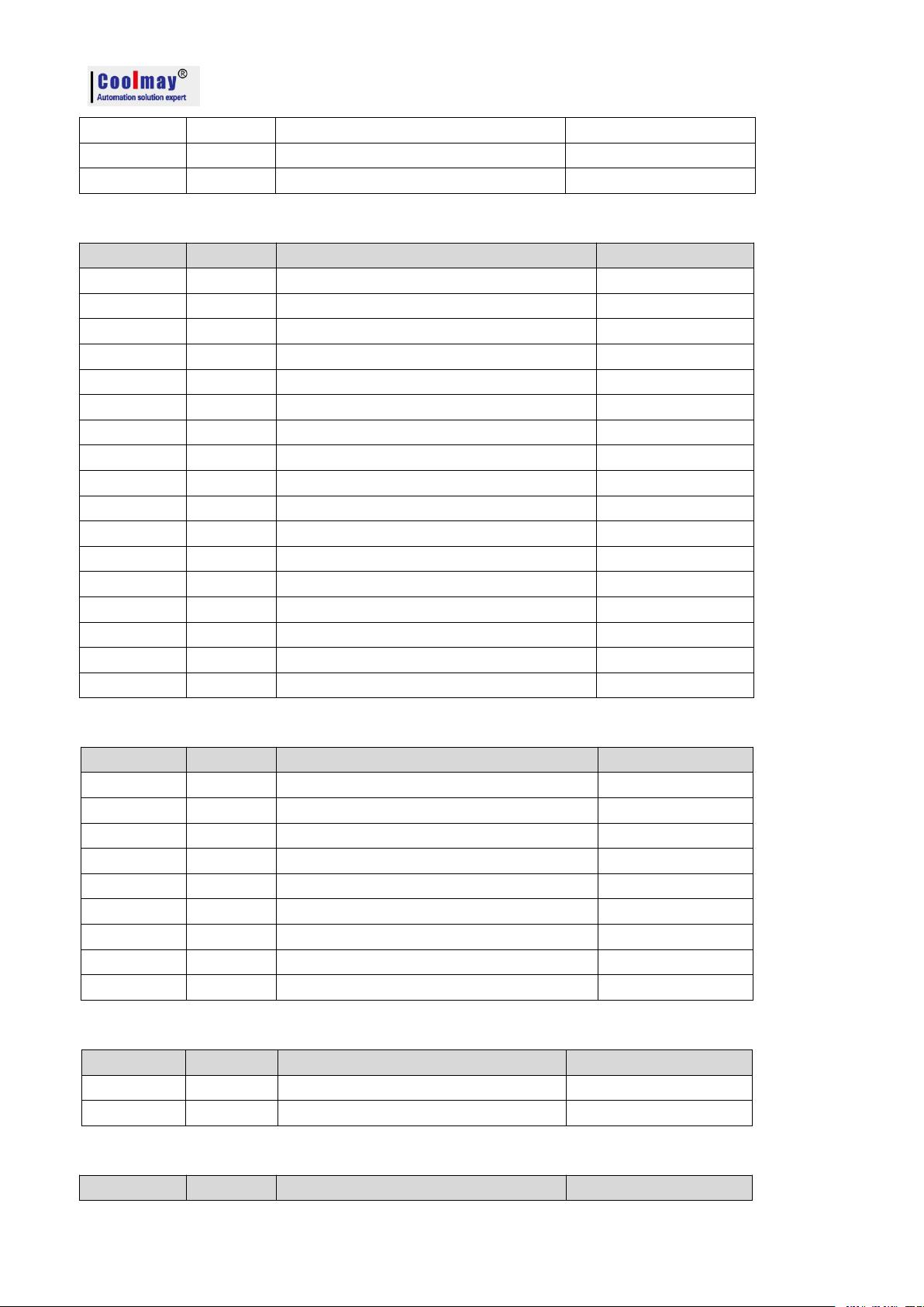
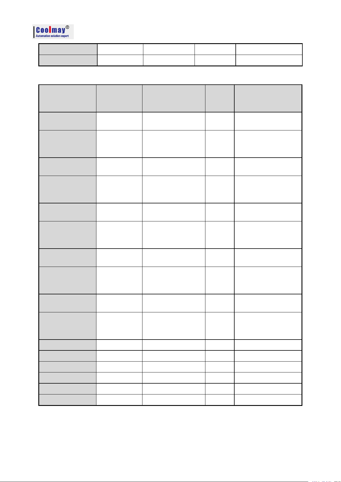
1.2 Models of CX3G PLC
Models
CX3G-16M
CX3G-24M
CX3G-32M
CX3G-48M
CX3G-34M
CX3G-64M
CX3G-80M
Image
Dimension
85*90*36mm
125*90*36mm
195*90*36mm
285*90*36mm
Cutout size
77*99mm
117*99mm
187*99mm
277*99mm
Installation
Fixed hole installation and DIN-Rail (35mm )
Digital I/O
8DI/8DO
12DI/12DO
16DI/16DO
24DI/24DO
18DI/16DO
32DI/32DO
40DI/40DO
I/O level
MT Output: NPN MR output: NO contact
Input: Passive NPN, public terminal isolated
Output type
Relay MR/Transistor MT/Both MRT
Maximum load of transistor is 500mA;Maximum load of relay is 5A
High speed
counting
Normally 6 single-phase 60KHz or 2 AB(Z) phases 60KHz + 1 10KHz;
High speed
pulse
Up to 8 channels. Y0-Y3 is 100KHz, Y4-Y7is 10KHz.
High-speed counting + high-speed pulse total output can not exceed 480KHz
Analog I/O
AI:0-10V/4-20mA/0-20mA/PT100/PT1000 /NTC10K/NTC50K/NTC100K /EKJST thermcouple (support negative
temperaturetc.
AO:0-10V/0-5V/0-20mA/4-20mA or mixed ones
Null
8AD/4DA
2AD/2DA
8AD/4DA
12AD/8DA
16AD/8DA
4AD/4DA
6AD/4DA
2DA
COM port
Two programming port(1 Mini B type USB port,faster downloading speed;1 Rs232,Interface terminal is mouse
female port with 8 holes)
The total number of COM ports is 2. The default is 2 RS485;
Or customized as 1 RS485, 1 RS232;
Or customized as a RS485, 1 CAN;
Or customized as a RS232, 1 CAN.
The total number of COM ports is 3.
The default 2 RS485;
Or customized as 1 RS485, 1 RS232;
Optional CAN.
Programmi
ng software
Compatible with WORKS 2/ GX Developer 8.86
Regular models:CX3G-16MT/MR/MRT(-485/232)CX3G-22MT/MR/MRT(-8AD4DA -485/232)
CX3G-24MT/MR/MRT(-6AD4DA -485/232)CX3G-30MT/MR/MRT(-2AD2DA -485/232)
CX3G-32MT/MR/MRT(-2AD -485/232)CX3G-34MT/MR/MRT(-12AD8DA -485/232)
CX3G-48MT/MR/MRT(-8AD4DA -485/232)CX3G-64MT/MR/MRT(-16AD8DA -485/232)
CX3G-80MT/MR/MRT(-4AD4DA -485/232)
Detailed info. refer to:COOLMAY CX3G/ FX3GC PLC Programming Manual
Support interruption,linear and arc interpolated,PID and modify parameters automatically; with capacity of 32K step program, 32K
holding register while power off.
*CX3G-24M,if with 8AD,maximum digits are 10DI;
*CX3G-32M,if with 2AD/2DA,maximum digits are 16DI/14DO.
CX3G/FX3GC PLC Programming manual
3
Page 6

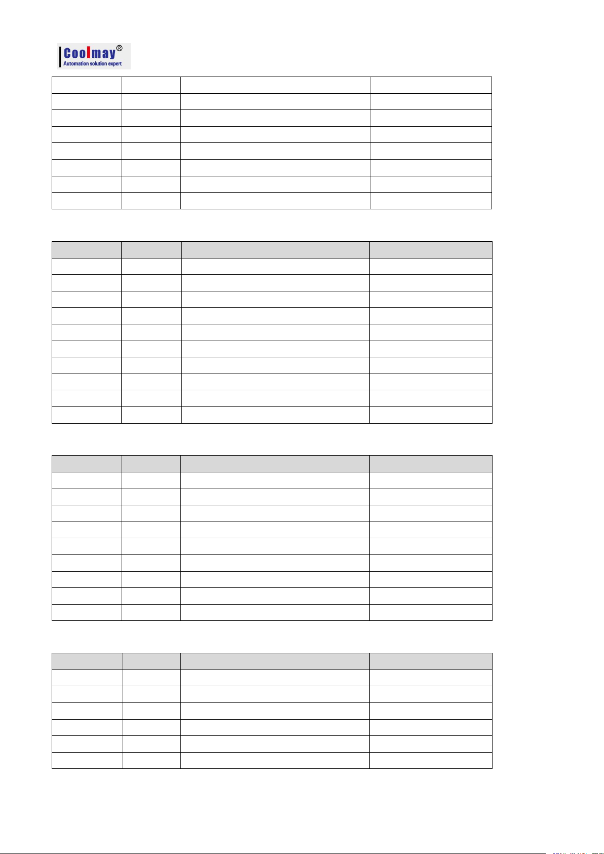
1.3 Models of FX3GC PLC
Artical
FX3GC-16M
Communication/analog extension module
can be added
FX3GC-30M(-485)
FX3GC-32M
Image
Dimension
90*60*32mm
Installation
Fixed hole installation and DIN-Rail (35mm)
Digital I/O
Up to 8DI/8DO
Up to 16DI/14DO
Up to 16DI/16DO
I/0 level
MT Output: NPN MR output: NO contact
Input: Passive NPN, public terminal isolated
Output Type
Relay MR/Transistor MT/Both MRT
Maximum load of transistor is 500mA;Maximum load of relay is 5A
High-speed
counting
Normally 4 single-phase 60KHz+2 10KHz or 2-3 AB(Z) phases up to 60KHz;
Can be specially customized 6 single phase 100KHz or 2 AB(Z) 60KHz+1 10KHz
High-speed
pulse output
Up to 8 channels. Y0-Y3 is 100KHz, Y4-Y7is 10KHz. Customized 8 channels 10-100KHz;
High-speed counting + high-speed pulse total output can not exceed 480KHz
Analog I/O
AI:0-10V/4-20mA/0-20mA/PT100/PT1000/K type thermocouple /NTC10K/NTC50K/NTC100K etc.
AO:0-10V/0-5V/0-20mA/4-20mA or mixed ones
Analog extension module can be added
NULL
COM port
Two programming port(1 Mini-B type USB port,faster downloading speed;1 Rs422,Interface terminal
is 8 holes mouse female port)
Rs485/CAN extension module can be added
Optional 1 RS485
NULL
Software
Compatible with Mitsubishi WORKS 2/GX Developer8.86
Regular models: FX3GC-16/32MT/MR/MRT
FX3GC-30MT/MR/MRT(-485)
Detailed info. refer to:COOLMAY CX3G/ FX3GC PLC Programming Manual
Support interruption、linear and arc interpolated、PID and modify parameters automatically; with capacity of 32K step
program, 32K holding register while power off.
Extension module can add at most 2 RS485,1 CAN port,6AD4DA,
Or 1 RS485,1 CAN port,8AD4DA,
Or 1RS485,8AD8DA,
Or 2 RS485,1 CAN port.
CX3G/FX3GC PLC Programming manual
4
Page 7
2.1 Soft element table
Name
Contents
I/O relay
Input relay
X000~X047
40points
Soft element number is octal
Total 80points for I/O
Output relay
Y000~Y047
40points
Auxiliary relay
General
M0~M383
384 points
EEPROM hold
M384~M1535
1152 points
General*1
M1536~M7679*2
6144 points
Special*3
M8000~M8511
512 points
Status
Initial state (EEPROM hold)
S0~S9
10 points
EEPROM hold
S10~S899
890 points
Signal Alert (EEPROM hold)
S900~S999
100 points
General*1
S1000~S4095
3096 points
Timer (ON delay timer)
100ms
T0~T191
200
points
0.1~3,276.7s
10ms
T200~T245
46 points
0.01~327.67s
1ms accumulative
(EEPROM hold)
T246~T249
4 points
0.001~32.767s
100ms accumulative
(EEPROM hold)
T250~T255
6 points
0.1~3,276.7s
1ms
T256~T319
64 points
0.001~32.767s
Counter
General up counter (16bit)
C0~C15
16 points
0~32,767 counter
EEPROM hold up counter
(16 bit)
C16~C199
184
points
0~32,767counter
General bi-direction (32 bit)
C200~C219
20 points
-2,147,483,648~+2,147,483,647
counter
EEPROM hold bi-direction
(32 bit)
C220~C234
15 points
-2,147,483,648~+2,147,483,647
counter
High-speed counter
Single-phase single counter input
Bi-direction (32 bit) (EEPROM
hold)
C235~C245
-2,147,483,648~+2,147,483,647 Counter Software
counter
Single phase:at most 6 channel, 60kHz
Double phase:Double frequency:at most 2-3
channels,60KHz; M8198 is 4 times frequency sign of
C251.
Quad frequency:at most 2-3 channels,
24kHz,M8199 is 4 times frequency sign of C253.
Single-phase double counter input
Bi-direction (32 bit) (EEPROM
hold)
C246~C250
Double –phase double counter
input
C251~C255
CX3G/FX3GC PLC Programming manual
2. Soft element
5
Page 8
CX3G/FX3GC PLC Programming manual
Bi-direction (32 bit)(EEPROM
hold)
Name
Contents
Data register(32 bit when using in pair)
General(16bit)
D0~D127
128 points
EEPROM hold (16 bit)
D128~D7999
7872 points
Special (16 bit)
D8000~D8511
512 points
Index (16 bit)
V0~V7,Z0~Z7
16 points
Extended register·extended file register
Extended register(16 bit)
R0~R22999
23000points Maintain when power off not supported
R23000~
R23999
1000points for system internal
Pointer
JUMP、CALL branch
P0~P255
P0~P1280
256 points
1281 points(26232 and above)
CJ instruct、CALL
instruct
Input interrupt
I0□□~I5□□
6points
Timer interrupt
I6□□~I8□□
3points
Nest
Master control
N0~N7
8points
MC instruct
Constant
Decimal (K)
16 bit
-32,768~+32,767
32 bit
-2,147,483,648~+2,147,483,647
Hexadecimal (H)
16 bit
0000~FFFF
32 bit
00000000~FFFFFFFF
Real number(E)*3
32 bit
-1.0×2128~-1.0×2-126,0,1.0×2-126~1.0×2128
Can be in the form of a decimal point and index
3. Special relay and register
Num
Content
Remarks
Num
Content
Remarks
M8000
In RUN,Normally closed
M8224
C224 Increase/decrease counting
action
ON:decrease
action
OFF:increase
action
M8001
In RUN,Normally open
M8225
C225 Increase/decrease counting
action
M8002
After RUN, Output a scan cycle
ON
M8226
C226 Increase/decrease counting
action
M8003
After RUN, Output a scan cycle
OFF
M8227
C227 Increase/decrease counting
action
M8011
Oscillating in 10ms cycle
M8228
C228 Increase/decrease counting
action
*1: The 10ms timer will be affected by the scan cycle. If the scan period is 12ms, the timer becomes 12ms and is executed once.
3.1 Special relay number and content
6
Page 9
CX3G/FX3GC PLC Programming manual
Num
Content
Remarks
Num
Content
Remarks
M8012
Oscillating in 100ms cycle
M8229
C229 Increase/decrease counting
action
M8013
Oscillating in 1s cycle
M8230
C230 Increase/decrease counting
action
M8014
Oscillating in 1min cycle
M8231
C231 Increase/decrease counting
action
M8020
Zero flag
M8232
C232 Increase/decrease counting
action
M8021
Borrowing flag
M8233
C233 Increase/decrease counting
action
M8022
Carry flag
M8234
C234 Increase/decrease counting
action
M8024
Specify BMOV direction
M8235
C235 Increase/decrease counting
action
ON:decrease
action
OFF:increase
action
M8028
During instruction
execution,allow interrupt
M8236
C236 Increase/decrease counting
action
M8029
Instruction execution end flag
M8237
C237 Increase/decrease counting
action
M8031
Non-retentive memory is cleared
M8238
C238 Increase/decrease counting
action
M8032
Retentive memory is cleared
M8239
C239 Increase/decrease counting
action
M8033
Memory retention stop
M8240
C240 Increase/decrease counting
action
M8034
Prohibit all output
M8241
C241 Increase/decrease counting
action
M8035
Forced RUN mode
M8242
C242 Increase/decrease counting
action
M8036
Force RUN command
M8243
C243 Increase/decrease counting
action
M8037
Force STOP command
M8244
C244 Increase/decrease counting
action
M8045
Prohibit reset of all outputs
M8245
C245 Increase/decrease counting
action
M8046
STL state action
M8246
C246 Increase/decrease counting
action
ON:decrease
action
OFF:increase
action
M8047
STL effective control
M8247
C247 Increase/decrease counting
action
M8048
Signal alarm action
M8248
C248 Increase/decrease counting
action
M8049
Signal alarm is effective
M8249
C249 Increase/decrease counting
action
7
Page 10
CX3G/FX3GC PLC Programming manual
Num
Content
Remarks
Num
Content
Remarks
M8050
Input interrupt (I00 is prohibited)
M8250
C250 Increase/decrease counting
action
M8051
Input interrupt (I10 is prohibited)
M8251
C251 Increase/decrease counting
action
M8052
Input interrupt (I20 is prohibited)
M8252
C252 Increase/decrease counting
action
M8053
Input interrupt (I30 is prohibited)
M8253
C253 Increase/decrease counting
action
M8054
Input interrupt (I40 is prohibited)
M8254
C254 Increase/decrease counting
action
M8055
Input interrupt (I50 is prohibited)
M8255
C255 Increase/decrease counting
action
M8056
Timer interrupt (I6 is prohibited)
M8340
1stpulse operation monitoring
M8057
Timer interrupt (I7 is prohibited)
M8342
Interpolation mode
26233 and lower
version
M8058
Timer interrupt (I8 is prohibited)
M8343
Interpolation mode
M8059
Counter interrupt is prohibited
M8344
Interpolation relative/absolute
coordinate
M8060
I/O Constitute error
M8348
Interpolation counterclockwise
26233and lower
version
M8061
PLC hardware error
M8341
Y000 clear signal output function is
valid
26234 and higher
version
M8062
Serial communication error 0
M8342
Y000 specify the origin return
direction
M8063
Serial communication error 1
M8343
Y000 forward limit
M8064
Parameter error
M8344
Y000 reverse limit
M8065
Grammatical error
M8345
Y000 near-point DOG signal logic
inversion
M8066
Loop error
M8346
Y000 zero signal logic inversion
M8067
Operation error
M8347
Y000 interrupt signal logic inversion
M8068
Operation error latch
M8348
Y000 positioning command driver
M8069
I/O bus detection
M8349
1st pulse stop
M8075
Sample tracking preparation start
command
M8350
2ndpulse operation monitoring
M8076
Sample tracking execution start
command
M8351
Y001 clear signal output function is
valid
M8077
Sample tracking execution
M8352
Y001 specify the origin return
direction
M8078
Sample tracking execution end
control
M8353
Y001 forward limit
M8079
Sampling tracking system area
M8354
Y001 reverse limit
M8120
Can't use
M8355
Y001 near-point DOG signal logic
inversion
8
Page 11

CX3G/FX3GC PLC Programming manual
Num
Content
Remarks
Num
Content
Remarks
M8121
RS/RS2 command sends standby
Serial Port
2
refer to
chapter
2.11
M8356
Y001 zero signal logic inversion
M8122
RS/RS2 command to send
request
M8357
Y001 interrupt signal logic inversion
M8123
RS/RS2 command reception end
M8358
Y001 positioning command driver
M8124
RS/RS2 command data in
reception
M8359
2nd pulse stop
M8125
MODBUS and Mitsubishi
function enablement
M8360
3rdpulse operation monitoring
M8128
RD3A/WR3A Receive
Completed
M8361
Y002 clear signal output function is
valid
M8129
RD3A/WR3A communication
timeout
M8362
Y002 specify the origin return
direction
M8151
5thpulse operation monitoring
M8363
Y002 forward limit
M8152
6thpulse operation monitoring
M8364
Y002 reverse limit
M8153
7thpulse operation monitoring
M8365
Y002 near-point DOG signal logic
inversion
M8154
8thpulse operation monitoring
M8366
Y002 zero signal logic inversion
M8160
XCH's SWAP function
M8367
Y002 interrupt signal logic inversion
M8161
8-bit processing mode
Software
26234 and
higher
M8368
Y002 positioning command driver
M8170
Input X000 pulse capture
M8369
3rd pulse stop
M8171
Input X001 pulse capture
M8370
4thpulse operation monitoring
M8172
Input X002 pulse capture
M8371
Y003 clear signal output function is
valid
M8173
Input X003 pulse capture
M8372
Y003 specify the origin return
direction
M8174
Input X004 pulse capture
M8373
Y003 forward limit
M8175
Input X005 pulse capture
M8374
Y003 forward limit
M8176
Input X006 pulse capture
M8375
Y003 near-point DOG signal logic
inversion
M8177
Input X007 pulse capture
M8376
Y003 zero signal logic inversion
M8192
Programming port protocol and
other protocol enablement
Serial
port3
M8377
Y003 interrupt signal logic inversion
M8196
Programming port protocol and
other protocol enablement
Serial
port2
M8378
Y003 positioning command driver
M8198
4 times frequency of C251, C252,
C254
M8379
4th pulse stop
M8199
4 times frequency of C253
M8396
C254 function corresponds to input
phase
Refer to chapter
2.9.1
M8200
C200 Increase/decrease counting
action
ON:decrea
se action
M8401
RS2 command sends standby
Serial port 3
Refer to chapter
9
Page 12

Num
Content
Remarks
Num
Content
Remarks
OFF:increa
se action
2.11.2
M8201
C201 Increase/decrease counting
action
M8402
RS2 command to send request
M8202
C202 Increase/decrease counting
action
M8403
RS2 command reception end
M8203
C203 Increase/decrease counting
action
M8404
RS2 command data in reception
M8204
C204 Increase/decrease counting
action
M8405
RS2 command data setting ready
M8205
C205 Increase/decrease counting
action
M8408
RD3A/WR3A Receive Completed
M8206
C206 Increase/decrease counting
action
M8409
RD3A/WR3A communication
timeout
M8207
C207 Increase/decrease counting
action
M8421
RS2 command sends standby
CAN
communication
Refer to chapter
2.11.4
M8208
C208 Increase/decrease counting
action
M8422
RS2 command to send request
M8209
C209 Increase/decrease counting
action
M8423
RS2 command reception end
M8210
C210 Increase/decrease counting
action
M8424
RS2 command data in reception
M8211
C211 Increase/decrease counting
action
M8425
RS2 command data send completed
M8212
C212 Increase/decrease counting
action
M8426
RS command master-slave and
multi-machine mode
M8213
C213 Increase/decrease counting
action
M8427
CAN data standard frame and
extended frame
M8214
C214 Increase/decrease counting
action
M8428
CAN communication MODBUS
response correct
M8215
C215 Increase/decrease counting
action
M8429
Communication timeout
M8216
C216 Increase/decrease counting
action
M8432
Interpolation mode
26235 and higher
version
M8217
C217 Increase/decrease counting
action
M8433
Interpolation mode
M8218
C218 Increase/decrease counting
action
M8434
Interpolation relative/absolute
coordinate
M8219
C219 Increase/decrease counting
action
M8435
Interpolation counterclockwise
M8220
C220 Increase/decrease counting
action
M8450
5th pulse stop
M8221
C221 Increase/decrease counting
action
M8451
6th pulse stop
CX3G/FX3GC PLC Programming manual
10
Page 13
Num
Content
Remarks
Num
Content
Remarks
M8222
C222 Increase/decrease counting
action
M8452
7th pulse stop
M8223
C223 Increase/decrease counting
action
M8453
8th pulse stop
3.2 Special register number and content
Num
Content
Remarks
Num
Content
Remarks
D8000
Watchdog timer
D8146
5th-8thpulse max speed
Low
D8001
PLC type and system version
Main version
number
D8147
High
D8002
PLC memory capacity
2...2K steps;
4...4K steps;
8...8K steps;
When 16K steps
and above,
D8002=8,D8102
is corresponded
to 16,32,64
D8148
5th- 8thpulse acceleration and
deceleration time
D8003
Memory type
10H:Programmab
le controller
built-in memory
D8160
8thposition pulse amount
Low
D8010
Scan current value
D8161
High
D8011
Scan time minimum
D8169
Restrict access status
D8012
Scan time maximum
D8182
Z1 Register contents
D8013
Second
D8183
V1 Register contents
D8014
Minute
D8184
Z2 Register contents
D8015
Hour
D8185
V2 Register contents
D8016
Date
D8186
Z3 Register contents
D8017
Month
D8187
V3 Register contents
D8018
Year
D8188
Z4 Register contents
D8019
Week
D8189
V4 Register contents
D8020
Input filter adjustment (0-60ms)
initial 10
D8190
Z5 Register contents
D8030
AD0 analog input value
D8191
V5 Register contents
D8031
AD1 analog input value
D8192
Z6 Register contents
D8032
AD2 analog input value
D8193
V6 Register contents
D8033
AD3 analog input value
D8194
Z7 Register contents
D8034
AD4 analog input value
D8195
V7 Register contents
D8035
AD5 analog input value
D8340
1stposition pulse amount
Low
D8036
AD6 analog input value
D8341
High
CX3G/FX3GC PLC Programming manual
11
Page 14
CX3G/FX3GC PLC Programming manual
Num
Content
Remarks
Num
Content
Remarks
D8037
AD7 analog input value
D8342
Y0 deviation speed
Initial value:0
D8038
AD8 analog input value
D8343
1stpulse maximum speed
Low
D8039
AD9 analog input value
D8344
High
D8040
AD10 analog input value
D8345
Y0 crawling speed
Initial value: 1000
D8041
AD11 analog input value
D8346
Y0 Origin return speed
Initial value:50000
Low
D8042
AD12 analog input value
D8347
High
D8043
AD13 analog input value
D8348
1stpulse acceleration time
D8044
AD14 analog input value
D8349
1stpulse deceleration time
D8045
AD15 analog input value
D8350
2ndposition pulse amount
Low
D8050
DA0 analog output value
D8351
High
D8051
DA1 analog output value
D8352
Y1 deviation speed
Initial value:0
D8052
DA2 analog output value
D8353
2ndpulse maximum speed
Low
D8053
DA3 analog output value
D8354
High
D8054
DA4 analog output value
D8355
Y1 crawling speed
Initial value: 1000
D8055
DA5 analog output value
D8356
Y1 Origin return speed
Initial value:50000
Low
D8056
DA6 analog output value
D8357
High
D8057
DA7 analog output value
D8358
2ndpulse acceleration time
D8058
When DA is current,Bit setting
Refer to 2.7
D8359
2ndpulse deceleration time
D8059
Constant scan time
D8360
3rdposition pulse amount
Low
D8074
X0 Rising edge ring counter value
[1/6μs unit]
Low
D8361
High
D8075
High
D8362
Y2 deviation speed
Initial value:0
D8076
X0 falling edge ring counter value
[1/6μs unit]
Low
D8363
3rdpulse maximum speed
Low
D8077
High
D8364
High
D8078
X0 pulse width / pulse period
[10μs unit]
Low
D8365
Y2 crawling speed
Initial value: 1000
D8079
High
D8366
Y2 Origin return speed
Initial value:50000
Low
D8080
X1 Rising edge ring counter value
[1/6μs unit]
Low
D8367
High
D8081
High
D8368
3rdpulse acceleration time
D8082
X1 falling edge ring counter value
[1/6μs unit]
Low
D8369
3rdpulse deceleration time
D8083
High
D8370
4thposition pulse amount
Low
D8084
X1 pulse width / pulse period
[10μs unit]
Low
D8371
High
D8085
High
D8372
Y3 deviation speed
Initial value:0
D8086
X3 Rising edge ring counter value
[1/6μs unit]
Low
D8373
4thpulse maximum speed
Low
D8087
High
D8374
High
D8088
X3 falling edge ring counter value
Low
D8375
Y3 crawling speed
12
Page 15
CX3G/FX3GC PLC Programming manual
Num
Content
Remarks
Num
Content
Remarks
[1/6μs unit]
Initial value:1000
D8089
High
D8376
Y3 Origin return speed
Initial value:50000
Low
D8090
X3 pulse width / pulse period
[10μs unit]
Low
D8377
High
D8091
High
D8378
4thpulse acceleration time
D8092
X4 Rising edge ring counter value
[1/6μs unit]
Low
D8379
4thpulse deceleration time
D8093
High
D8395
Network setting function
Refer to
chapter 2.12
D8094
X4 falling edge ring counter value
[1/6μs unit]
Low
D8397
ADPRW command serial port
position
Refer to
chapter 2.11.1
D8095
High
D8398
0~2147483647(1ms) Ring
count for incremental actions
D8096
X4 pulse width / pulse period
[10μs unit]
Low
D8399
D8097
High
D8400
Modbus RTU protocol
Communication parameters
Serial port3
Refer to
chapter 2.11.2
D8101
PLC type and system version
Secondary
version number
D8401
Communication mode
D8102
PLC memory capacity
16...16K steps
D8406
Number of intervals
D8108
Number of special modules
connected
D8409
overtime time
D8109
Y number of output refresh error
D8410
RS2 header 1, 2 <initial value:
STX>
D8120
Modbus RTU protocol
Communication parameters
Serial port2
Refer to chapter
2.11
D8411
RS2 header 3, 4
D8121
Master and slave station number
D8412
RS2 trailer 1, 2 <initial value:
ETX>
D8122
RS command to send data remaining
points
D8413
RS2 trailer 3, 4
D8123
RS command to receive points
monitoring
D8414
Master and slave station number
D8124
RS header <initial value: STX>
D8415
RS2 receives the summation
calculation result
D8125
RS trailer <initial value: ETX>
D8416
RS2 sends summation
D8126
When the serial port 2 uses the
ADPRW command, the value is 0.
26232 lower
D8420
Communication parameters
CAN
communication
Refer to
chapter 2.11.4
D8126
Serial port 2 interval period number
26232 and higher
D8421
Communication mode
D8127
Specify the starting number of the
communication request of the lower
computer
Serial port2
Refer to chapter
2.11
D8426
Number of intervals
D8128
Specify the number of data
requested by the lower computer
communication
D8429
overtime time
13
Page 16
CX3G/FX3GC PLC Programming manual
Num
Content
Remarks
Num
Content
Remarks
D8129
Set timeout
D8430
RS2 header 1, 2 <initial value:
STX>
D8140
5thposition pulse amount
Low
D8431
RS2 header 3, 4
D8141
High
D8432
RS2 trailer 1, 2 <initial value:
ETX>
D8142
6thposition pulse amount
Low
D8433
RS2 trailer 3, 4
D8143
High
D8434
RS2 receives the summation
receive data
D8144
7thposition pulse amount
Low
D8435
RS2 receives the summation
calculation result
D8145
High
D8436
RS2 sends summation
Special relay and register not supported
※ Special relay not supported
M8004~M8010,M8015~M8019,M8024~M8027,M8030,M8038~M8039,M8040~M8044,
M8060~M8074,M8084~M8119,M8130~M8159,M8161~M8169,M8178~M8191,
M8256~M8339,M8370~M8395,M8430~M8511.
Note:26234 and later version support M8161.
※ special register not supported
D8004~D8009,D8042~D8067,D8069~D8073,D8105~D8119,D8150~D8168,
D8200~D8329,D8468~D8511.
Specific functions please refer to 《Mitsubishi FX3G programming manual》
14
Page 17
CX3G/FX3GC PLC Programming manual
1
Data move instructions
2
Data conversion instructions
3
Comparison instructions
4
Arithmetic operation instructions
5
Logical operation instructions
6
Special function instructions
7
Rotate instructions
8
Data operation instructions
9
Data operation instructions
10
Character string operation instructions
11
Program flow control instructions
12
I/O refresh instructions
13
Real time clock control instructions
14
Pulse output/positioning control instructions
15
Serial communication
16
Special block/unit control instructions
17
Extension register/extension file register control instructions
18
Other handy instruct
1. Data move instructions
Mnemonic
FNC No.
Function
Support
MOV
12
Move
★
SMOV
13
Shift Move
★
CML
14
Compliment
★
BMOV
15
Block Move
★
FMOV
16
Fill Move
★
PRUN
81
Parallel Run (Octal Mode)
★
XCH
17
Exchange
★
SWAP
147
Byte Swap
★
EMOV
112
Floating Point Move
★
HCMOV
189
High Speed Counter Move
★
2. Data conversion instructions
Mnemonic
FNC No.
Function
Support
BCD
18
Conversion to Binary Coded Decimal
★
4. Function Instructions
Applied instructions【Sequence is according to instruct variety
(Contrast with MITSUBISHI)
Applied instruction can be divided into the following 18 kinds.
】
15
Page 18
CX3G/FX3GC PLC Programming manual
BIN19Conversion to Binary
★
GRY
170
Decimal to Gray Code Conversion
★
GBIN
171
Gray Code to Decimal Conversion
★
FLT
49
Conversion to Floating Point
★
INT
129
Floating Point to Integer Conversion
★
EBCD
118
Floating Point to Scientific Notation
Conversion
★
EBIN
119
Scientific Notation to Floating Point
Conversion
★
RAD
136
Floating Point Degree to Radian
Conversion
★
DEG
137
Floating Point Radian to degree Conversion
★
3. Comparison instructions
Mnemonic
FNC No.
Function
Support
LD=
224
Contact compare LD
(S1)=(S2)
★
LD>
225
Contact compare LD
(S1)>(S2)
★
LD<
226
Contact compare LD
(S1)<(S2)
★
LD<>
228
Contact compare LD
(S1)≠(S2)
★
LD<=
229
Contact compare LD
(S1)≦(S2)
★
LD>=
230
Contact compare LD
(S1)≧(S2)
★
AND=
232
Contact compare AND
(S1)=(S2)
★
AND>
233
Contact compare AND
(S1)>(S2)
★
AND<
234
Contact compare AND
(S1)<(S2)
★
AND<>
236
Contact compare AND
(S1)≠(S2)
★
AND<=
237
Contact compare AND
(S1)≦(S2)
★
AND>=
238
Contact compare AND
(S1)≧(S2)
★
OR=
240
Contact compare OR
(S1)=(S2)
★
OR>
241
Contact compare OR
(S1)>(S2)
★
OR<
242
Contact compare OR
(S1)<(S2)
★
OR<>
244
Contact compare OR (S1)≠(S2)
★
OR<=
245
Contact compare OR (S1)≦(S2)
★
OR>=
246
Contact compare OR (S1)≧(S2)
★
CMP
10
Compare
★
ZCP
11
Zone Compare
★
ECMP
110
Floating Point Compare
★
EZCP
111
Floating Point Zone Compare
★
HSCS
53
High speed counter set
★
HSCR
54
High speed counter reset
★
HSZ
55
High Speed Counter Zone Compare
★
HSCT
280
High speed counter table compare
★
BKCMP=
194
Block compare (S1)=(S2)
★
16
Page 19
CX3G/FX3GC PLC Programming manual
BKCMP>
195
Block compare (S1)>(S2)
★
BKCMP<
196
Block compare (S1)<(S2)
★
BKCMP<>
197
Block compare (S1)≠(S2)
★
BKCMP<=
198
Block compare (S1)≦(S2)
★
BKCMP>=
199
Block compare (S1)≧(S2)
★
4. Arithmetic operation instructions
Mnemonic
FNC No.
Function
Support
ADD
20
Addition
★
SUB
21
Subtraction
★
MUL
22
Multiplication
★
DIV
23
Division
★
EADD
120
Floating Point Addition
★
ESUB
121
Floating Point Subtraction
★
EMUL
122
Floating Point Multiplication
★
EDIV
123
Floating Point Division
★
BK+
192
Block Data Addition
★
BK-
193
Block Data Subtraction
★
INC
24
Increase
★
DEC
25
Decrement
★
5. Logical operation instructions
Mnemonic
FNC No.
Function
Support
WAND
26
Word AND
★
WOR
27
Word OR
★
WXOR
28
Word Exclusive OR
★
6. Special function instructions
Mnemonic
FNC No.
Function
Support
SQR
48
Square Root
★
ESQR
127
Floating Point Square Root
★
EXP
124
Floating Point Exponent
★
LOGE
125
Floating Point Natural Logarithm
★
LOG10
126
Floating Point Common Logarithm
★
SIN
130
Floating Point Sine
★
COS
131
Floating Point Cosine
★
TAN
132
Floating Point Tangent
★
ASIN
133
Floating Point Arc Sine
★
ACOS
134
Floating Point Arc Cosine
★
ATAN
135
Floating Point Arc Tangent
★
RND
184
Random Number Generation
★
17
Page 20
CX3G/FX3GC PLC Programming manual
7. Rotate instructions
Mnemonic
FNC No.
Function
Support
ROR
30
Rotation Right
★
ROL
31
Rotation Left
★
RCR
32
Rotation right With Carry
★
RCL
33
Rotation Left with Carry
★
8. Shift instructions
Mnemonic
FNC No.
Function
Support
SFTR
34
Bit Shift Right
★
SFTL
35
Bit Shift Left
★
SFR
213
Bit Shift Right with Carry
★
SFL
214
Bit Shift Left with Carry
★
WSFR
36
Word Shift Right
★
WSFL
37
Word Shift left
★
SFWR
38
Shift Write [FIFO/FILO Control]
★
SFRD
39
Shift Read [FIFO Control]
★
POP
212
Shift Last Data Read [FILO Control]
★
9. Data operation instructions
Mnemonic
FNC No.
Function
Support
ZRST
40
Zone Reset
★
DECO
41
Decode
★
ENCO
42
Encode
★
MEAN
45
Mean
★
WSUM
140
Sum of Word Data
★
SUM
43
Sum of Active Bits
★
BON
44
Check Specified Bit Status
★
NEG
29
Negation
★
ENEG
128
Floating Point Negation
★
WTOB
141
WORD to BYTE
★
BTOW
142
BYTE to WORD
★
UNI
143
4-bit Linking of Word Data
★
DIS
144
4-bit Grouping of Word Data
★
CCD
84
Check Code
★
CRC
188
Cyclic Redundancy Check
★
LIMIT
256
Limit Control
★
BAND
257
Dead Band Control
★
ZONE
258
Zone control
★
SCL
259
Scaling (Coordinate by Point Data)
★
SCL2
269
Scaling 2 (Coordinate by X/Y Data)
★
SORT
69
Sort Tabulated Data
★
SORT2
149
Sort Tabulated Data 2
★
18
Page 21
CX3G/FX3GC PLC Programming manual
SER61Search a Data Stack
★
FDEL
210
Deleting Data from Tables
★
FINS
211
Inserting Data to Tables
★
10. String processing instruction
Mnemonic
FNC No.
Function
Support
ESTR
116
Floating Point to Character String Conversion
★
EVAL
117
Character String to Floating Point Conversion
★
STR
200
BIN to Character String Conversion
★
VAL
201
Character String to BIN Conversion
★
DABIN
260
Decimal ASCII to BIN Conversion
★
BINDA
261
BIN to Decimal ASCII Conversion
★
ASCI
82
Hexadecimal to ASCII Conversion
★
HEX
83
ASCII to Hexadecimal Conversion
★
$MOV
209
Character String Transfer
★
$+
202
Link Character Strings
★
LEN
203
Character String Length Detection
★
RIGH
204
Extracting Character String Data From the Right
★
LEFT
205
Extracting Character String Data from the Left
★
MIDR
206
Random Selection of Character Strings
★
MIDW
207
Random Replacement of Character Strings
★
INSTR
208
Character string search
★
COMRD
182
Read Device Comment Data
★
11. Program flow control instructions
Mnemonic
FNC No.
Function
Support
CJ00Conditional Jump
★
CALL
01
Call Subroutine
★
SRET
02
Subroutine Return
★
IRET
03
Interrupt Return
★
EI04Enable Interrupt
★
DI05Disable Interrupt
★
FEND
06
Main Routine Program End
★
FOR
08
Start a FOR/NEXT Loop
★
NEXT
09
End a FOR/NEXT Loop
★
12. I/O refresh instructions
Mnemonic
FNC No.
Function
Support
REF50Refresh
★
REFF
51
Refresh and Filter Adjust
★
13. Real time clock control instructions
Mnemonic
FNC No.
Function
Support
19
Page 22
CX3G/FX3GC PLC Programming manual
TCMP
160
RTC Data Compare
★
TZCP
161
RTC Data Zone Compare
★
TADD
162
RTC Data Addition
★
TSUB
163
RTC Data Subtraction
★
TRD
166
Read RTC data
★
TWR
167
Set RTC data
★
HTOS
164
Hour to Second Conversion
★
STOH
165
Second to Hour Conversion
★
14. Pulse output/positioning control instruction
Mnemonic
FNC No.
Function
Support
ABS
155
Absolute Current Value Read
★
DSZR
150
DOG Search Zero Return
★
ZRN
156
Zero Return
★
TBL
152
Batch Data Positioning Mode
★
DVIT
151
Interrupt Positioning
★
DRVI
158
Drive to Increment
★
DRVA
159
Drive to Absolute
★
PLSV
157
Variable Speed Pulse Output
★
PLSY
57
Pulse Y Output
★
PLSR
59
Acceleration/Deceleration Setup
★
15. Serial communication instructions
Mnemonic
FNC No.
Function
Support
RS80Serial Communication
★
R(S2)
87
Serial Communication 2
★
IVCK
270
Inverter Status Check
IVDR
271
Inverter Drive
IVRD
272
Inverter Parameter Read
IVWR
273
Inverter Parameter Write
IVBWR
274
Inverter Parameter Block Write
IVMC
275
Inverter multiple command
ADPRW
276
MODBUS read and write
★
16. Special block/unit control instructions
Mnemonic
FNC No.
Function
Support
FROM
78
Read From a Special Function Block
★
TO
79
Write To a Special Function Block
★
RD3A
176
Read form Dedicated Analog Block
★
WR3A
177
Write to Dedicated Analog Block
★
RBFM
278
Divided BFM Read
WBFM
279
Divided BFM Write
20
Page 23
CX3G/FX3GC PLC Programming manual
17. Extension register/extension file register control instructions
Mnemonic
FNC No.
Function
Support
LOADR
290
Load From ER
SAVER
291
Save to ER
RWER
294
Rewrite to ER
INITR
292
Initialize R and ER
INITER
295
Initialize ER
LOGR
293
Logging R and ER
18. Other handy instructions
Mnemonic
FNC No.
Function
Support
WDT
07
Watchdog Timer Refresh
★
ALT66Alternate State
★
ANS46Timed Annunciator Set
★
ANR
47
Annunciator Reset
★
HOUR
169
Hour Meter
★
RAMP
67
Ramp Variable Value
★
SPD56Speed Detection
★
PWM
58
Pulse Width Modulation
★
DUTY
186
Timing Pulse Generation
★
PID88PID Control Loop
★
ZPUSH
102
Batch Store of Index Register
★
ZPOP
103
Batch POP of Index Register
★
TTMR
64
Teaching timer
★
STMR
65
Special timer
★
ABSD
62
Absolute Drum Sequencer
★
INCD
63
Incremental Drum Sequencer
★
ROTC
68
Rotary Table Control
★
IST60Initial state
★
MTR
52
Input Matrix
★
TKY
70
Ten Key Input
★
HKY
71
Hexadecimal Input
★
DSW
72
Digital switch (thumbwheel input)
★
SEGD
73
Seven Segment Decoder
★
SEGL
74
Seven Segment With Latch
★
ARWS
75
Arrow Switch
★
ASC76ASCII code data input
★
PR77Print (ASCII Code)
★
VRRD
85
Volume Read
★
VRSC
86
Volume Scale
★
21
Page 24
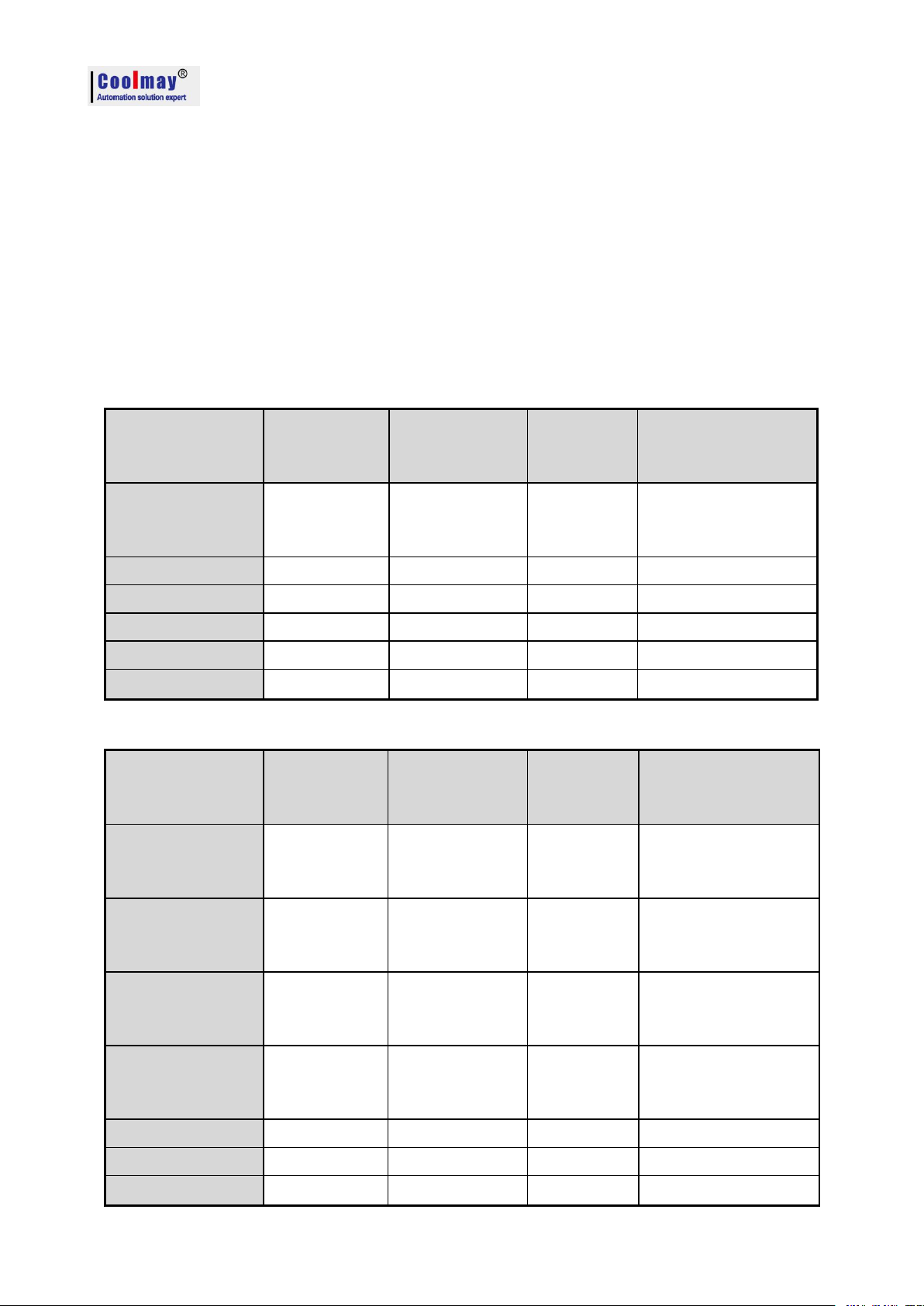
CX3G/FX3GC PLC Programming manual
Input signal
Range
Register value
Resolution
Accuracy
(Total Measuring
range)
K-type
thermocouple
0~1100℃
Room
temperature ~
11000
0.1℃
1%
PT100
-200~350
℃
-2000~3500
0.1℃1%
NTC10K
-48~210
℃
-480~2100
0.1℃1%
Voltage
0~10V/0-5V
0~4000
2.5mV
1%
Current Type1
0~20mA
0~4000
5uA
1%
Current Type2
4~20mA
0~4000
4uA
1%
Input signal
Range
Register value
Resolution
Accuracy
(Total Measuring
range)
K-type
thermocouple
0~1100℃
Room
temperature ~
11000
0.1℃
1%
K-type
thermocouple
(Negative temp)
-210~
1200℃
-2100~12000
0.1℃
1%
T-type
thermocouple
0~420
℃
Room
temperature
~
4200
0.1℃1%
T-type
thermocouple
(Negative temp)
-210~420℃
-2100~4200
0.1℃
1%
PT100/PT1000
-200~350℃
-2000~3500
0.1℃
1%
NTC
-48~210℃
-480~2100
0.1℃
1%
Voltage
0~10V/0-5V
0~4000
2.5mV
1%
5. Application of analog
This section refers to the software version query, the version number is stored in the special
register D8001, if necessary, please query the value of D8001.
5.1 Analog input
Input precision of coolmay CX3G/FX3GC PLC and EX3G plc hmi all-in-one is 12-bit, directly
read the corresponded register value of each analog while using. Environment temperature is only
used in K-type thermocouple.
5.1.1 Analog input (temperature)
Below table for software version 26210
Below table for software version 26220
22
Page 25
Current Type1
0~20mA
0~4000
5uA
1%
Current Type2
4~20mA
0~4000
4uA
1%
Below table for software version 26230 and above
Input signal
Range
Register value
Resolut
ion
Accuracy
(Total Measuring
range)
K-type
thermocouple
0~1100
℃
Room temperature
~
11000
0.1
℃
1%
K-type
thermocouple
(Negative temp)
-230
~
1370
℃
-2300~13700
0.1
℃
1%
T-type
thermocouple
0~400℃
Room temperature
~4000
0.1℃
1%
T-type
thermocouple
(Negative temp)
-230~400℃
-2300~4000
0.1℃
1%
S-type
thermocouple
0~1690
℃
Room temperature
~
16900
0.1
℃
1%
S-type
thermocouple
(Negative temp)
-40~1690
℃
-400~16900
0.1
℃
1%
J-type
thermocouple
0~800℃
Room temperature
~8000
0.1℃
1%
J-type
thermocouple
(Negative temp)
-90~950℃
-900~9500
0.1℃
1%
E-type
thermocouple
0~600
℃
Room temperature
~
6000
0.1
℃
1%
S-type
thermocouple
(Negative temp)
-110~730
℃
-1100~7300
0.1
℃
1%
PT100/PT1000
-200~500℃
-2000~5000
0.1℃
1%
NTC50K/100K
-48~210
℃
-480~2100
0.1
℃
1%
NTC10K
-48~110℃
-480~1100
0.1℃
1%
Voltage
0~10V/0-5V
0~4000
2.5mV
1%
Current Type1
0~20mA
0~4000
5uA
1%
Current Type2
4~20mA
0~4000
4uA
1%
CX3G/FX3GC PLC Programming manual
The transmitter which is integrated inside PLC is one of the above table or mixed ones, it is up
to customers’s need when ordering.
23
Page 26

CX3G/FX3GC PLC Programming manual
NO
Register Value
AD0
R23680
AD1
R23681
AD2
R23682
AD3
R23683
AD4 (Environment
temperature)
R23684
AD5
R23685
AD6
R23686
AD7
R23687
AD8
R23688
AD9
R23689
AD10
R23690
AD11
R23691
AD12
R23692
AD13
R23693
AD14
R23694
AD15
R23695
NO
PT100
register read
value
NTC10K
register read
value
0~10V/0-5V or
0~20mA
register read value
4~20mA
register read
value
AD0
R23640
R23660
D8030
R23620
AD1
R23641
R23661
D8031
R23621
AD2
R23642
R23662
D8032
R23622
AD3
R23643
R23663
D8033
R23623
AD4
R23644
R23664
D8034
R23624
AD5
R23645
R23665
D8035
R23625
AD6
R23646
R23666
D8036
R23626
AD7
R23647
R23667
D8037
R23627
AD8
R23648
R23668
D8038
R23628
AD9
R23649
R23669
D8039
R23629
AD10
R23650
R23670
D8040
R23630
AD11
R23651
R23671
D8041
R23631
AD12
R23652
R23672
D8042
R23632
5.1.2 Analog input reading 1 (for software version 26210 and 26220)
Support FROM instruction or register directly read. Such as: FROM K0 K0 D400 K16, read
out 16 analog input, 0-10V.
The K-type thermocouple registers read values are shown in the following table:
A decimal points should be retained for temperature. Namely 182=18.2℃.
Other types of read values are as the following table:
24
Page 27

CX3G/FX3GC PLC Programming manual
AD13
R23653
R23673
D8043
R23633
AD14
R23654
R23674
D8044
R23634
AD15
R23655
R23675
D8045
R23635
NO
K-type (negative
temperature) register read
value
T-type register
read value
T-type (negative
temperature) register read
value
AD0
R23720
R23700
R23740
AD1
R23721
R23701
R23741
AD2
R23722
R23702
R23742
AD3
R23723
R23703
R23743
AD4
(Environment
temperature)
R23724
R23704
R23744
AD5
R23725
R23705
R23745
AD6
R23726
R23706
R23746
AD7
R23727
R23707
R23747
AD8
R23728
R23708
R23748
AD9
R23729
R23709
R23749
AD10
R23730
R23710
R23750
AD11
R23731
R23711
R23751
AD12
R23732
R23712
R23752
AD13
R23733
R23713
R23753
AD14
R23734
R23714
R23754
AD15
R23735
R23715
R23755
NO
Register Value
AD0
D8030
AD1
D8031
AD2
D8032
AD3
D8033
When it is less than 3.8mA, the value is 32760, that is break value.
5.1.3 Analog input reading 2 (for software version 26220)
Thermocouple K-type (negative temperature), T-type, T-type (negative temperature) register
read value are as the table below.
5.1.4 Analog input reading 3 (for software version 26230 and above)
Support FROM instructions or register read directly. Such as: FROM K0 K0 D400 K16 read
16 analog input, 0~10V.
The analog input of current, voltage, PT type and thermocouple type directly reads the register:
D[8030]~D[8045]. Constant scan time changed to D8059, started by M8039 (version 26232 and
higher).
25
Page 28

CX3G/FX3GC PLC Programming manual
AD4
(Environment temperature)
D8034
AD4
D8035
AD5
D8036
AD6
D8037
AD7
D8038
AD8
D8039
AD9
D8040
AD10
D8041
AD11
D8042
AD12
D8043
AD13
D8044
AD14
D8045
NO.
Register value
AD0
R23660
AD1
R23661
AD2
R23662
AD3
R23663
AD4
(Environment temperature)
R23664
AD5
R23665
AD6
R23666
AD7
R23667
AD8
R23668
AD9
R23669
AD10
R23670
AD11
R23671
AD12
R23672
AD13
R23673
AD14
R23674
AD15
R23675
Register No
Read value
Signal type
Remark
R23940~R23955
0
0~10V(or 0~20mA)
These 4 types analog
input type uses
R23940~R23955
1
4~20mA
When the analog input has a thermocouple type, it can only do up to 15 channels, of which
AD4 is the ambient temperature of the thermocouple. 16 channels are possible without the
thermocouple type.
The value of the thermistor NTC is read in the 16thregisters starting at R23660.
Except the thermistor NTC,all types of analog readings are read directly by D[8030]~D[8045],
so analog input type needs to be set as below:
26
Page 29

CX3G/FX3GC PLC Programming manual
different hardware
and cannot be
changed after the
value is set.
R23940~R23955
2
PT100\PT1000
R23940~R23955
3
10K\50K\100K NTC
R23940~R23943
R23945~R23955
4
K Type thermocouple positive
temperature
The thermocouple
type has little
difference in
hardware usage, and
can be modified to
other thermocouple
types even after the
read value is set.
R23940~R23943
R23945~R23955
5
K Type thermocouple negative
temperature
R23940~R23943
R23945~R23955
6
T Type thermocouple positive
temperature
R23940~R23943
R23945~R23955
7
T Type thermocouple negative
temperature
R23940~R23943
R23945~R23955
8
S Type thermocouple positive
temperature
R23940~R23943
R23945~R23955
9
S Type thermocouple negative
temperature
R23940~R23943
R23945~R23955
10
J Type thermocouple positive
temperature
R23940~R23943
R23945~R23955
11
J Type thermocouple negative
temperature
R23940~R23943
R23945~R23955
12
E Type thermocouple positive
temperature
R23940~R23943
R23945~R23955
13
E Type thermocouple negative
temperature
Namely, the 5th R23944 must be set less than 4.
R23960 starts with a zero correction value and defaults to 0.
R23960 starts with a zero correction value and default is 0 (Namely, size correction).
R23980 starts with a negative temperature amplification. The default is 4633 (temporarily only
have negative temperature amplification).
The 16 registers starting from R23620 are 0~10V or 0~20mA corresponding values, that is,
real-time sampled values.
5.1.5 Analog input sampling
Filtering cycles=( R23600~R23615)* PLC scanning time, if R23600=1, sample one time each
scan circle and change the 1stanalog value for one time. The larger R23600~R23615 value is, the
result is more stable.
R23600~R23615 is filtering cycles, default is 100 (Range 2~20000);
D8073 is smoothing filter coefficients of all analog input, range: 0~999
5.1.6 Analog input program example:
Below is an example of the CX3G 1 channel temperature analog AD0 acquisition. The program
reads the values as follows:
27
Page 30

CX3G/FX3GC PLC Programming manual
Connect the signal terminal of the temperature sensor to the AD0 input of the PLC and the
other end to the GND of the analog input port.
When the PLC is running, the value of the data register D8030 corresponding to AD0 will be
transmitted to D0, the value of D0 will be put into D10 after floating point operation,
and then the floating point number division operation will be performed on D10, and then
operation result will be put into D20, the result D20 is the actual Temperature value.
In the ladder diagram, you can also directly divide the value of D8030.
Note: When the input is 0-10V analog, the actual analog value = register reading / 400;
When the input is temperature, the actual temperature value = register reading/10;
When the input is 0-20mA analog, the actual analog value = register reading / 200;
When the input is 4-20 mA analog, the actual analog value = register reading / 250 + 4.
The analog correction is corrected for the size. The following figure is an example of correcting
the AD0 temperature after acquisition:
If the current temperature is 37.9℃,the actual test is 47.9 ° C, the error is 10 ° C, you need to
modify the size correction register, show as below:
28
Page 31

CX3G/FX3GC PLC Programming manual
DA register
Range
Output type
DA0
D8050
0-4000
When D8058.0~D8058.7=0
Means 0~20mA;
When D8058.0~D8058.7=1
Means 4~20mA.
DA1
D8051
0-4000
DA2
D8052
0-4000
DA3
D8053
0-4000
DA4
D8054
0-4000
DA5
D8055
0-4000
DA6
D8056
0-4000
DA7
D8057
0-4000
In the above figure, when M0 is closed, the value -100 is transmitted to the correction register
R23960, and now you can see that the value of the actual measured temperature D20 is close to the
actual temperature which is 37.9 °C.
5.2 Analog output
Analog output range 0~4000, precision is 12 bit. Support TO instruction or register assignment
operation directly.
Adopts TO K0 K0 D500 K8, 8 channels 0~10V or 0~20mA analog output.
Register assignment operation directly: D8050~D8057.
When the analog output is current, the bit of D8058 needs to be set:
When the default D8058.0~D8058.7=0, it means 0~20mA; when D8058.0~D8058.7=1, it means
4~20mA.
For example:
Below shows the 0-10V voltage analog output.
At this point, use a multimeter to check the voltage of the DA0 terminal, that is, the
multimeter's red pen is connected to the DA0 terminal, and the black pen is connected to the GND
terminal. The multimeter is displaying 5V voltage value.
5.3 PID instruction
Detailed information please refer to <Mitsubishi FX3G Programming Manual>
The self-tuning method in the PID instruction has only a step response mode. The step value is
S0+22.
29
Page 32
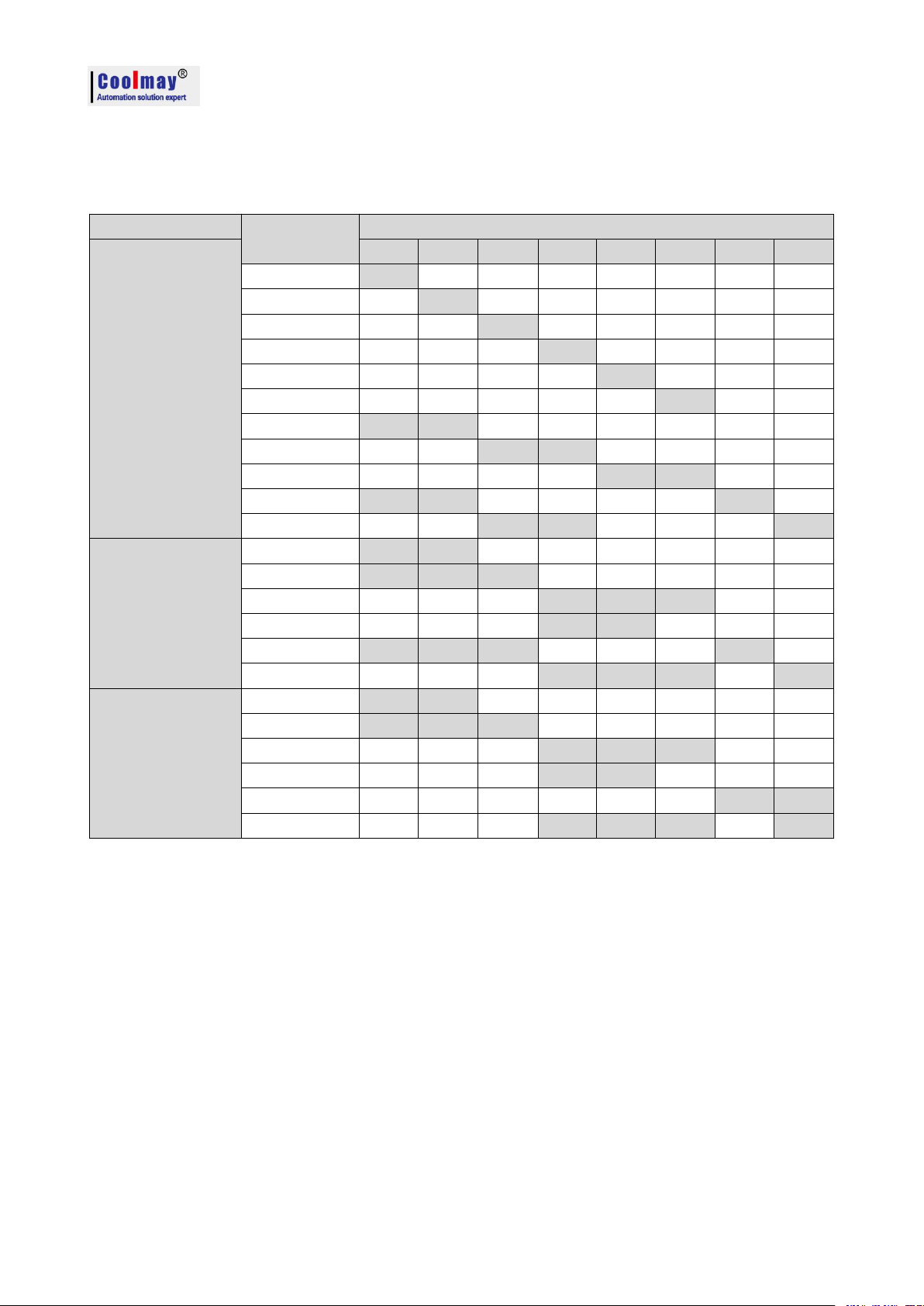
6. Application of high speed counter
Assignment table of built-in high speed counter
Counter type
No.
Input assignment
Single phase
single counter
input
X000
X001
X002
X003
X004
X005
X006
X007
C235
U/D
C236
U/D
C237
U/D
C238
U/D
C239
U/D
C240
U/D
C241
U/D
R
C242
U/D
R
C243
U/D
R
C244
U/D
R
S
C245
U/D
R
S
Single phase
double counter
input
C246
U
D
C247
UDR
C248
UDR
C248(OP)*1
U
D
C249
UDR
S
C250
UDR
S
AB phase double
counter input
C251
A
B
C252
ABR
C253
ABR
C253(OP)*1
A
B
C254(OP)*1
A
B
C255
ABR
S
CX3G/FX3GC PLC Programming manual
U: up counter D: down counter
A: A phase input B:B phase input
R: External reset input S: External start input
Single phase: at most 6 channels, max frequency is 60KHz
AB phase: Double frequency: at most 2-3 channels, max frequency is 60KHz; M8198 is 4 times
frequency sign of C251.
times frequency sign of C253.
* High speed input C254:
When M8396=0, the original C254 is AB phase corresponded to X3 X4.
When M8396=1, C254 changes to AB phase corresponded to X6 X7.
Quadruplicated frequency: at most 2-3 channels, max frequency is 24KHz; M8199 is 4
30
Page 33
CX3G/FX3GC PLC Programming manual
7. Application of high speed pulse
Pulse point
Function
Description
Y0Y1Y2Y3Y4Y5Y6
Y7
Pulse operation
monitoring
M8340
M8350
M8360
M8370
M8151
M8152
M8153
M8154
Position pulse
(32bit)
D8340
D8341
D8350
D8351
D8360
D8361
D8370
D8371
D8140
D8141
D8142
D8143
D8144
D8145
D8160
D8161
accelerate /
decelerate time
D8348
D8349
D8358
D8359
D8368
D8369
D8378
D8379
D8148
D8148
D8148
D8148
Pulse stop bit
M8349
M8359
M8369
M8379
M8450
M8451
M8452
M8453
Maximum speed
D8343
D8344
D8353
D8354
D8363
D8364
D8373
D8374
D8146
D8147
D8146
D8147
D8146
D8147
D8146
D8147
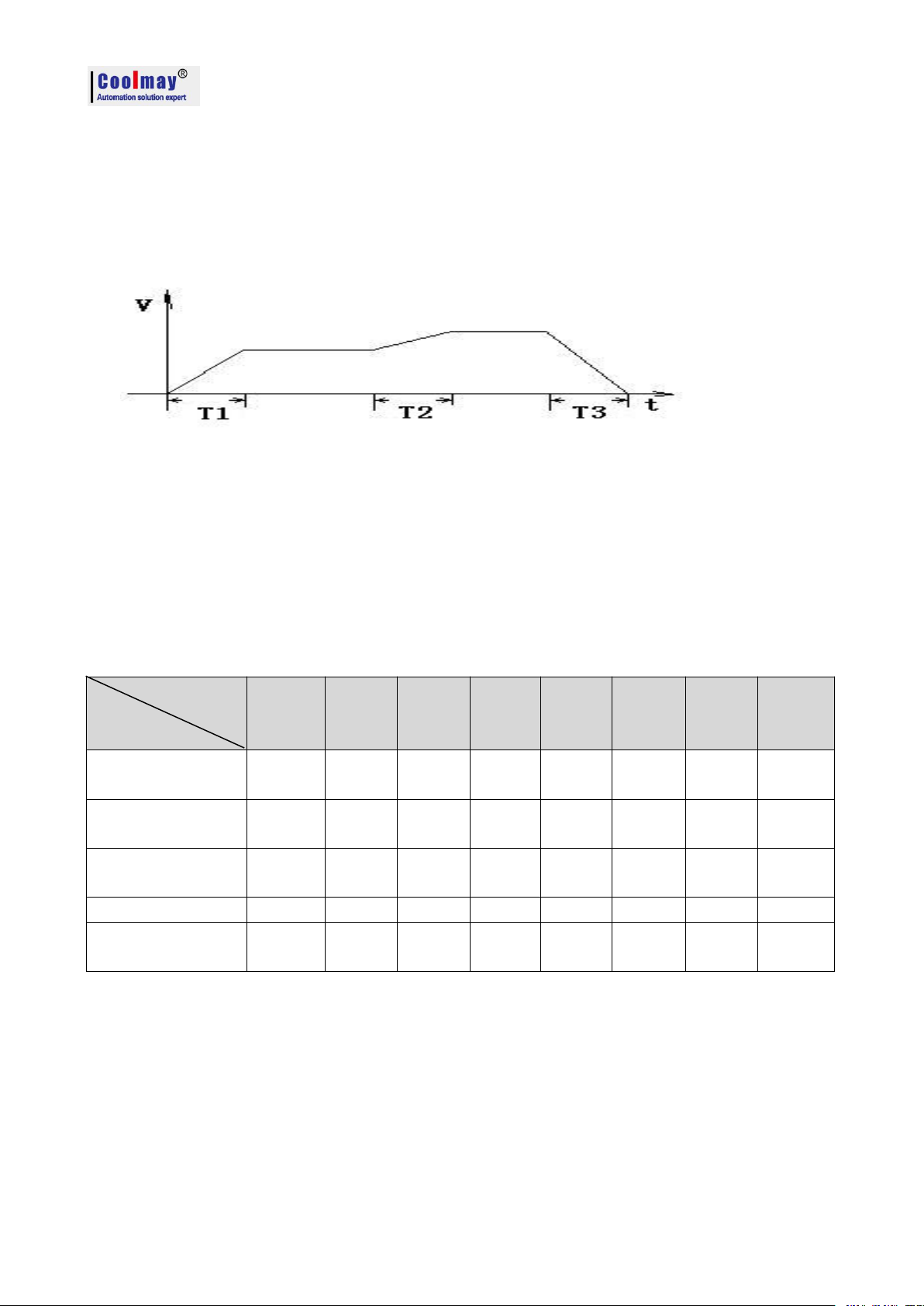
7.1 high speed pulse output
Coolmay CX3G default has 8 channels high speed pulse, Y0-Y3 each 100KHz, Y4-Y7 each
10KHz,variable speed supported, the initial/final speed of start/stop is 0, diagram as below: (take
accelerate and decelerate time D8148 as an example).
Acceleration/deceleration time T calculation= (target speed-current speed) *
acceleration/deceleration time÷maximum speed.
For example, target speed = 50000, current speed = 20000, acceleration time 100 (ms), maximum
speed = 100,000, T = 30 ms.
CX3G: 8 channels of pulse, the last 4 channels of acceleration and deceleration = D8148, the
maximum speed is D8146, D8147.
PLSY, ZRN, PLSV, DRVI, DRVA, DVIT, DSZR, only Y0-Y3 supports DVIT (interrupt
positioning), DSZR (originary return with DOG search) instructions.
The original FX3G pulse program can be used directly.
All the instruction support 8 channels pulse, except DVIT、DSZR which support 4 channels.
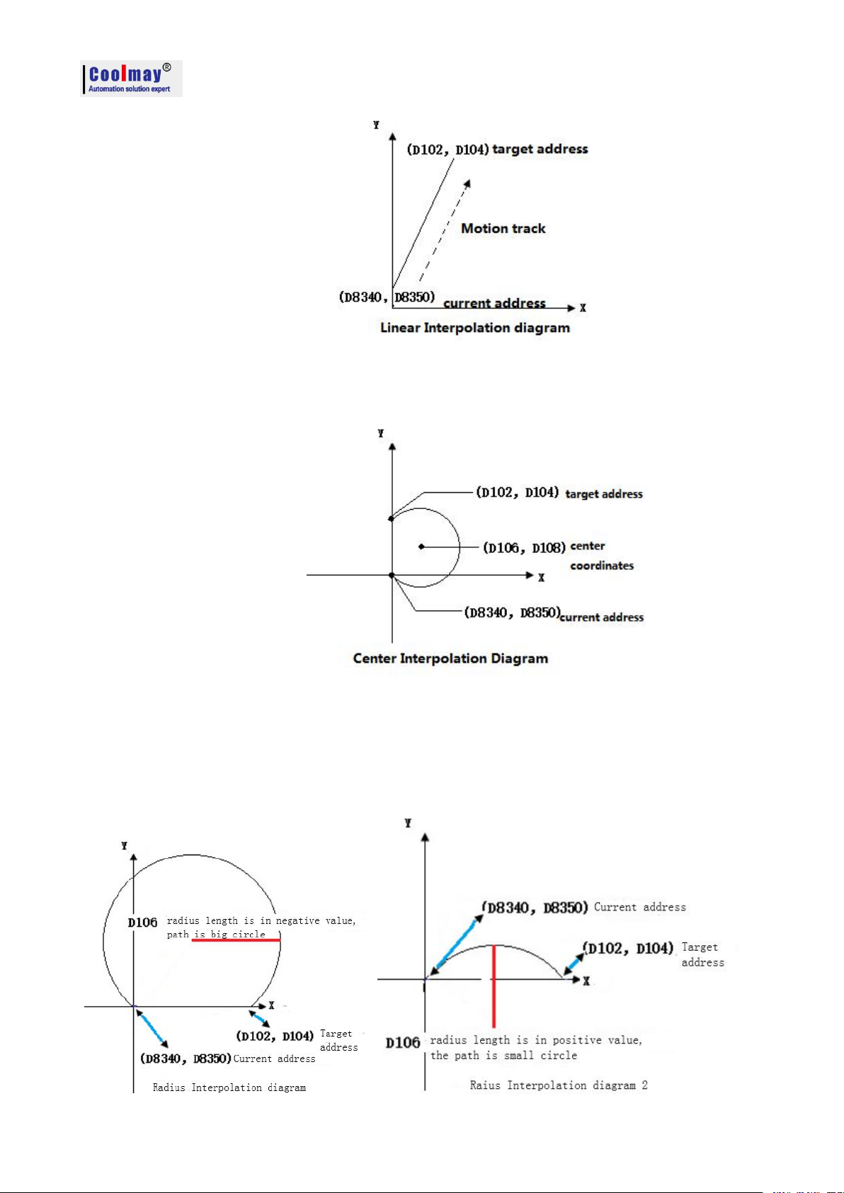
7.2 Circular interpolation
7.2.1 Continuous interpolation function
The special flags when setting the interpolation route are as shown in the following table: (26234
version has no interpolation function)
31
Page 34
CX3G/FX3GC PLC Programming manual
26235 version and above
Interpolation mode
M8433
M8432
Line Interpolation
0
1
Center interpolation
1
0
Radius interpolation
1
1
26233 version and above
Clockwise
M8348 = 0
Anticlockwise
M8348 = 1
Relative coordinate
M8344 = 0
Absolute coordinate
M8344 = 1
S. represents the pulse frequency, that is, the speed of the interpolation motion.
26233 version and above
Interpolation mode
M8343
M8342
Line Interpolation
0
1
Center interpolation
1
0
Radius interpolation
1
1
26235 version and above
Clockwise
M8435 = 0
Anticlockwise
M8435 = 1
Relative coordinate
M8434 = 0
Absolute coordinate
M8434 = 1
The direction and coordinates of the center and radius interpolation are as shown in the following
table: (26234 version has no interpolation function)
D8340 shows the current address of X axis,D8350 shows the current address of Y axis。
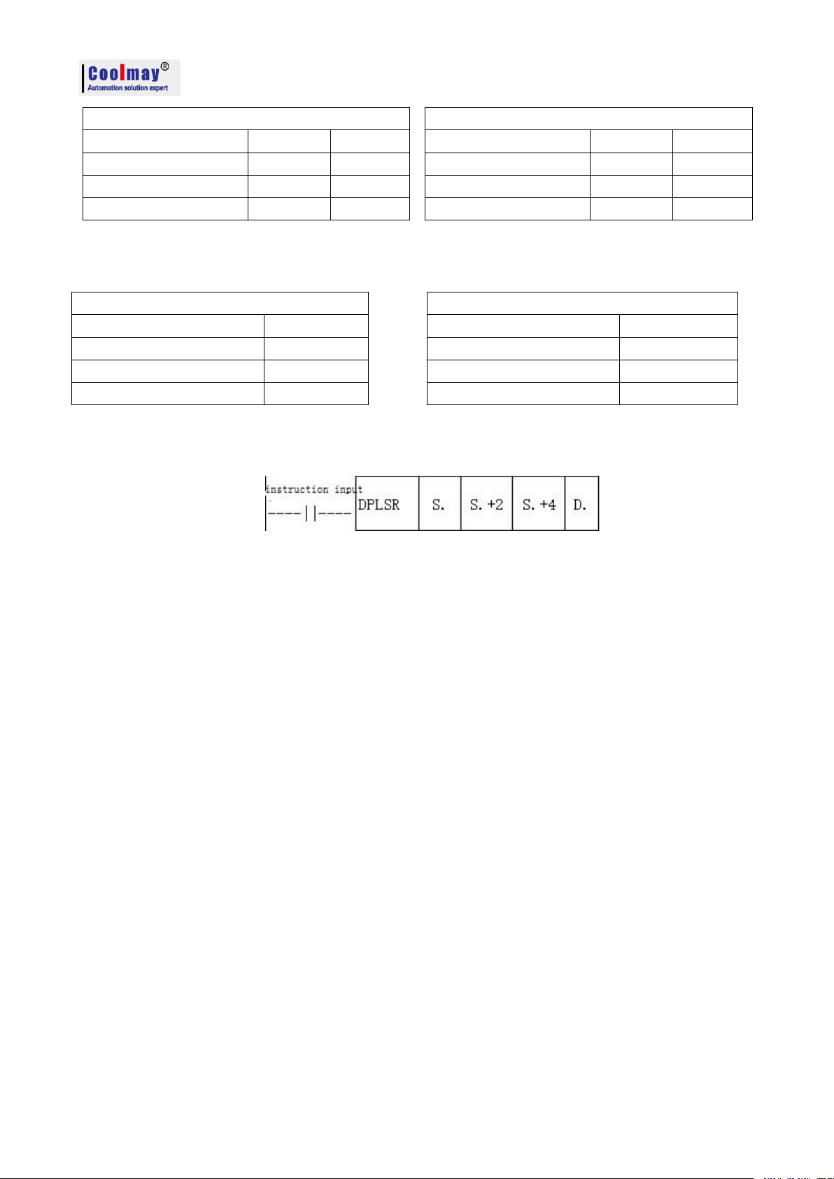
In CoolMay 3G PLC,interpolation motion still adopts DPLSR for pulse output.
Description of the Operand:
S.+2 represents the X-axis target address.
S.+4 represents the Y-axis target address.
D.: Specify the Y number with pulse output (currently only Y0 is supported), and the default Y1
is another axis.
X axis: Y0 pulse, Y4 direction
Y axis: Y1 pulse, Y5 direction
In the center interpolation mode:
S.+6 represents the center X coordinate address.
S.+8 represents the center Y coordinate address.
In radius interpolation mode:
S.+6 represents the radius length. When it is positive, the path is a small circle; when it is a
negative value, the path is a large circle.
For example: DPLSR D100 D102 D104 Y000
In the linear interpolation: D100 speed, D102 is the X-axis target address, and D104 is the Y-axis
target address.Y0 and Y1 respectively pulse the X-axis and Y-axis.
32
Page 35
CX3G/FX3GC PLC Programming manual
In the Center interpolation: D100 speed, D102 is the X-axis target address, D104 is the Y-axis
target address, and D106 is the center X address. D108 is the center Y address. Y0 and Y1
respectively pulse the X-axis and Y-axis.
Note 1: The current address of X and Y must be on the same circle as the destination address.
Note 2: When the current address coincides with the target address, it indicates that the motion track
is a full circle.
In the radius interpolation: D100 speed, D102 is the X-axis target address, D104 is the Y-axis target
address, and D106 is the radius length. Y0 and Y1 respectively pulse the X-axis and Y-axis.
33
Page 36
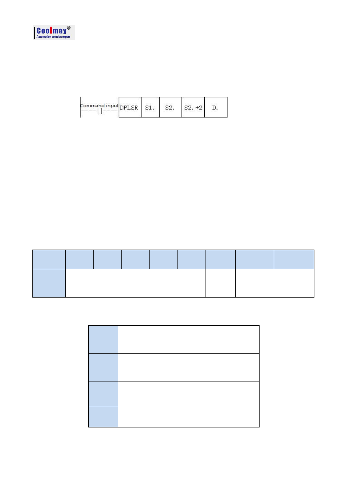
CX3G/FX3GC PLC Programming manual
32bit
position
b31~b28
b27~b24
b23~b20
b19~b16
b15~b12
b11~b8
b7~b4
b3~b0
Function
Continuous interpolation
execution and stop
Flag position
Position
mode
Interpolation
direction
Interpolation
mode
b3~b0
=1:linear mode interpolation
=2:center mode interpolation
=3: radius mode interpolation
b7~b4
=0: clockwise rotation
=1: counterclockwise rotation
= any other value: linear mode
b11~b8
=1:relative position
=2:absolute position
b31~b12
=00000:continuous interpolation execution
=AAAAA:continuous interpolation stop
7.2.2 Continuous interpolation function
M8436 is the flag for the normal interpolation mode and continuous interpolation mode.
M8436=0: regular interpolation mode;
M8436=1: continuous interpolation mode;
In CoolMay 3G PLC 26236 and higher version, continuous interpolation motion uses DPLSR for
pulse output.
Operand Description: All use 32-bit registers.
S1. indicates the pulse frequency, that is, the speed of the interpolation motion.
S2. indicates the X-axis target address.
S2.+2 indicates the Y-axis target address.
In the center mode: S2.+4 and S2.+6 indicates the Center coordinates.
In radius mode: S2.+4 indicates the radius length, and S2.+6 ignores and unused.
S2.+4 positive value: the path is a small circle;
S2.+4 negative value: the path is a big circle.
S2.+8 is the control register.
D.: Specify the Y number with pulse output (only Y0 supported), and the default Y1 is another axis.
In continuous interpolation mode, M8432~M8435 are determined by the 5thparameter (ie S.+10).
The function description of each bit of the 32-bit register S2.+8 is as follows:
When S2.+8 is used, it is expressed in hexadecimal. The bit values of each group are as below
shown :
PS: When using linear mode interpolation, b7~b4 is ignored and can be set to any value from 2~F.
S1. and S2. may be set discontinuous. For example, S1.=D100, S2.=D120.
S2. Must be consecutive with the next four 32-bit registers. For example, it must be set to D102,
34
Page 37

D104, D106, D108, D110.
For example: draw a line and two arcs, as shown:
Program as below :
CX3G/FX3GC PLC Programming manual
35
Page 38
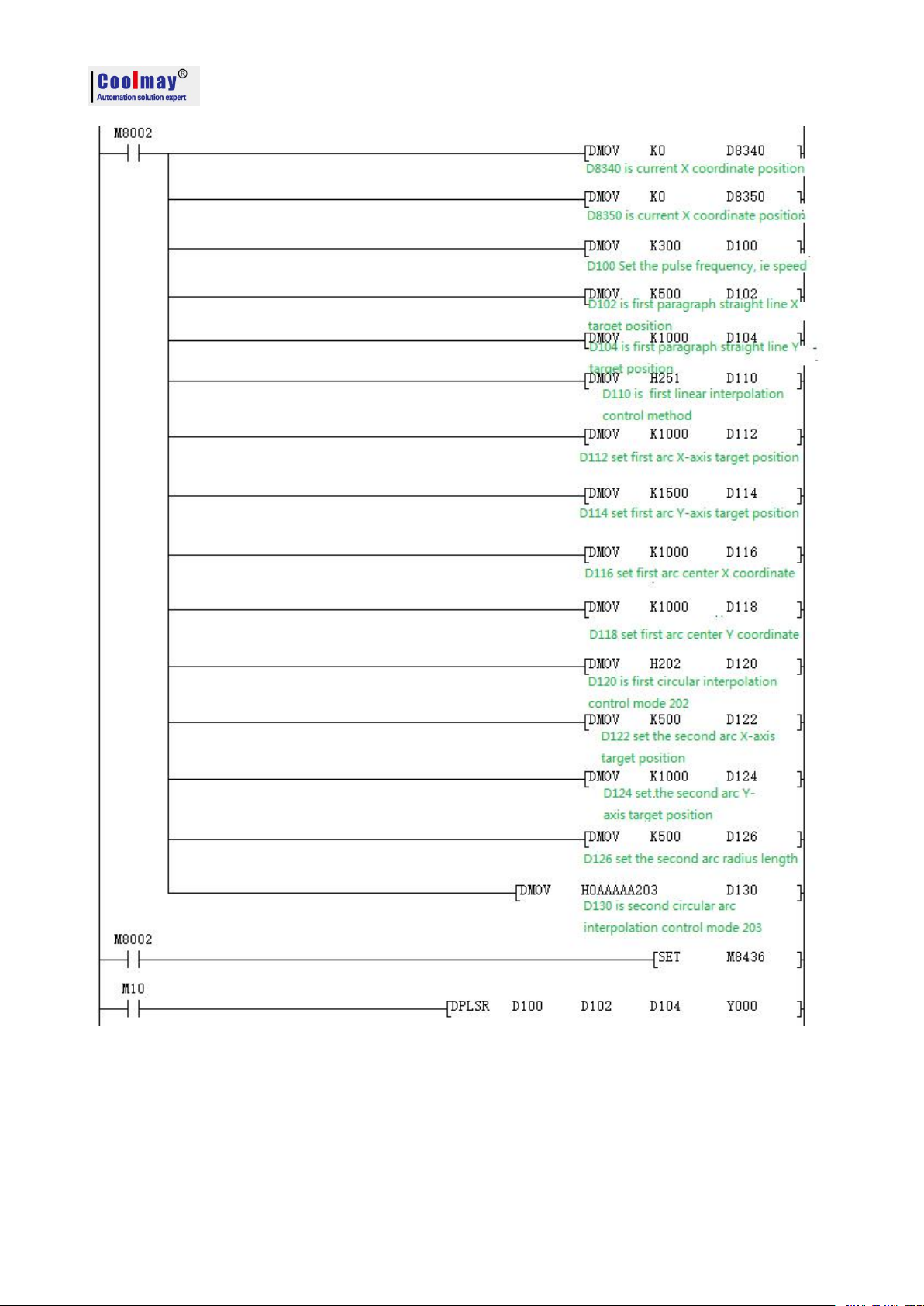
CX3G/FX3GC PLC Programming manual
36
Page 39

CX3G/FX3GC PLC Programming manual
Functions
Serial port
2(A/B)
Serial port
3(A1/B1)
CAN(H/L)
Remark
Mitsubishi programming
port protocol
M8196=0
M8192=0
-
26232 or higher version:
power lost can not be retentive
RS port protocol
M8196=1
M8125=0
M8192=1
-
RS sending mark
M8122=1
M8402=1
M8422=1
Need manual reset
RS sending completion
-
-
M8425
Need manual reset
RS receiving completion
M8123
M8403
M8423
Need manual reset
RS receiving process
M8124
M8404
M8424
Data is receiving
RS command 8/16 bits
differentiation
M8161
M8161
M8161
RS command CAN
master-slave
-
-
M8426
M8426=0 master-slave mode,
M8426=1 multi-device mode
RS command end
operation settings
012
MODBUS RTU function
M8196=1
M8125=1
M8192=1
-
RD3A\WR3A receiving
completion
M8128
M8408
M8428
Need manual reset
RD3A\WR3A
communication over-time
M8129
M8409
M8429
Need manual reset
ADPRW command
completion mark
M8029
M8029
M8029
Command execution end mark
Communication
parameters
D8120
D8400
D8420
Communication mode
-
D8401
D8421
8. Coolmay CX3G PLC Communication User Manual
CX3G PLC defaulted has a RS232 programming port, and two communication ports ( Rs232 or
Rs485) can be added. Meanwhile, CANbus is also optional.
8.1 Serial port 1: RS232( PLC programming port)
Support Mitsubishi programming port protocol;Can be used to download PLC program or
communicate with devices which support MITSUBISHI programming port protocol.
8.2 Serial port 2: RS485(A B)/RS232
Support MITSUBISHI programming port protocol,Mitsubishi BD board protocol,RS protocol
and MODBUS RTU protocol.
The special relays and registers related to this serial port are as below.
37
Page 40
CX3G/FX3GC PLC Programming manual
Master-slave station
number
D8121
D8414
D8434
D8440
D8442
D8434:CAN slave station NO
D8440\D8442 multi-device
mode ID NO
RD3A/WR3A overtime
D8129
D8409
D8429
Unit: ms
RD3A/WR3A interval
period
D8126
D8406
D8426
26232 or higher version
RD3A\WR3A end
operation -1
012
ADPRW command
settings
D8126=0
D8126=1
D8126=2
26232 or lower version
ADPRW command
settings
D8397=0
D8397=1
D8397=2
26232 or higher version
CAN data frame
-
-
M8427
M8196: the activation mark of using programming port protocol and other protocol. (26232 or
higher version is power lost not retentive.)
M8125: the activation flag of using MODBUS and the original Mitsubishi function.
M8122: RS2 command send mark (this bit needs to be set 1 when using the RS instruction).
M8123: RS2 command receiving completion mark, needs manual reset.
M8124: RS2 command data is receiving.
M8161: 8-bit/16-bit mode distinguishing flag for RS/RS2 instruction (used in version 26230 and
above, always in 8-bit mode in versions 26210 and 26220)
M8128: RD3A/WR3A receiving completion mark, needs manual reset.
M8129: RD3A/WR3A communication overtime mark (this mark is ON while communication
overtime).
M8029: Communication completion flag (communication completion flag when using ADPRW
instruction, needs to be reset by hand).
D8120: The detailed communication parameter settings of saving Modbus RTU protocol are seen as
below.
D8121: Save the host or slave station number. (It must be set as max. K255 as master)
D8129: RD3A and WR3A time-out period. (Unit: ms. Better not over 100ms while setting).
D8126: When using the serial port 2 in the ADPRW instruction, set D8126 to 0. (26232 or lower
version)
D8126: Interval period. Default as 10 times. (26232 or higher version uses this register.)
D8397: When using the serial port 2 in the ADPRW instruction, set D8397 to 0. (26232 and higher
version)
Support RS,WR3A,RD3A,ADPRW, Can be set in parameter zone,correspond to serial port 2.
Parameter zone settings are valid only for this channel. Invalid for serial port 3.
8.2.1 Mitsubishi programming port protocol
When used as programming port protocol: set M8196=0.
38
Page 41
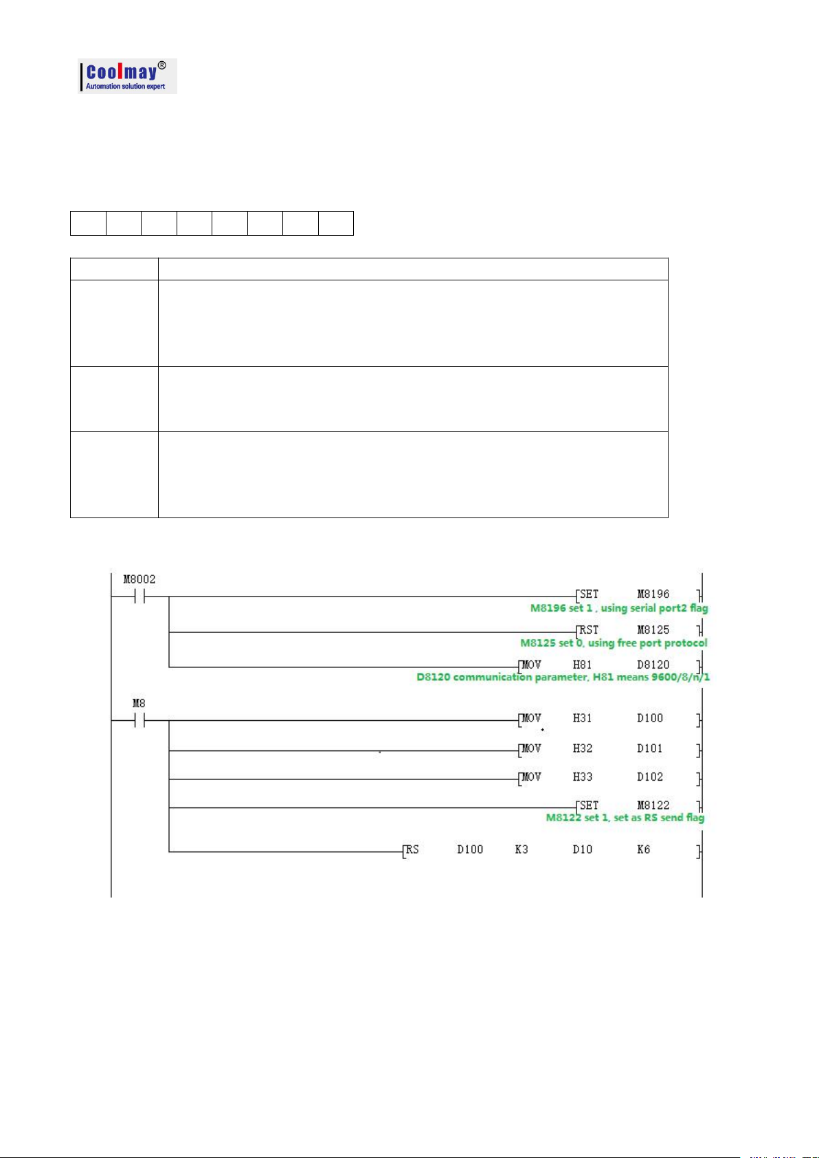
CX3G/FX3GC PLC Programming manual
b7b6b5b4b3b2b1
b0
b0
Data length 0:7 bits 1:8bits
b2b1Odd and Even
00: None
01: Odd
02: Even
b3
Stop bit
0: 1 bit
1: 2 bits
b4
b5
b6
b7
BPS rate (b7,b6,b5,b4)
(0100):600bps (0101):1200bps (0110):2400bps
(0111):4800bps (1000):9600bps (1001):19200bps
(1010):38400bps (1011):57600bps (1101):115200bps
8.2.2 Free port protocol
When used as MITSUBISHI protocol: set M8196=1,M8125=0; the difference between
Mitsubishi protocol 1 and protocol 4 is with end mark OA OD ( stored in D8124, D8125 separately)
For the Mitsubishi protocol, the D8120 only needs to set the lower 8 bits.
Demo program:
Use the serial port tool by serial port 2 to monitor the data obtained is
[2017:11:01:10:49:16][receive]31 32 33
8.2.3 Modbus RTU Protocol
When used as MOdbus RTU: set M8196=1,M8125=1; set D8120 as communication parameters,
D8121 set as slave station. For example: D8120=HE081,D8121=H1(communications parameter as
9600/8/n/1,station number is 1)
39
Page 42

CX3G/FX3GC PLC Programming manual
Bit number
Content
b0
Data length
0:7 bit
1:8 bit
b2
b1
Parity
00:None
01:Odd
11:Even
b3
Stop bit
0:1 bit
1:2 bit
b4
b5
b6
b7
Baud rate (b7b6b5b4)
0100:600bps
0101:1200bps
0110:2400bps
0111:4800bps
1000:9600bps
1001:19200bps
1010:38400bps
1011:57600bps
1100:115200bps
b8
Set 0
b9
b10
b11
b12
Set 0
b13
Set 1
b14
Set 1
b15
Set 1
When PLC is as host, ADPRW,RD3A and WR3A is supported.
RD3A and WR3A only support the below MODBUS functions:
Function No. 03: Read holding register and takes the current binary value range of 1-32 in one or
more holding registers.
Function No. 06: Load the specific binary value into a holding register (write register) ,range:1.
Function No. 16: Preset multiple registers, load specific binary values into a series of consecutive
holding registers (write multiple registers),range:1-32.
Note! For 26231 below version The RD3A and WR3A must be triggered with a rising edge. For
26231 and above,it can be triggered by the normal signal.
D8120 Parameter set
40
Page 43

CX3G/FX3GC PLC Programming manual
Read slave data instruction function and action description:
RD3A originally referred to the analog module readout.
For CoolMay PLC, the RD3A instruction corresponds to Modbus's No. 03 function.
In the instruction,
m1 represents the station number of the read slave device,range:1-247;
m2 represents the first address number of the read data in the slave device;
D represents the number of registers read, range: 1-32, and the read data is sequentially stored
in the host D.+1, D.+2.
D-1 address value must be set to 0. (=0: serial port 2; =1: serial port 3; =2: CAN)
Program example:
Slave program:
Host program:
41
Page 44

CX3G/FX3GC PLC Programming manual
Program explanation:
D300 saves the numbers of registers read, which means that 10 data is read.
D299 must be set to 0.
This program represents that 10 data of the registers D100-D109 in the PLC with the slave station 1
are read and stored in the registers D301-D310 of the master station PLC.
Use the serial port tool to monitor the results:
[2017:07:05:17:41:20][receive]01 03 00 64 00 0A 84 12
[2017:07:05:17:41:20][receive]01 03 14 00 6F 00 DE 01 4D 01 BC 02 2B 02 9A 03 09 03 78 03 E7
00 00 7D 69
(This example sets the data of the slave D100-D109 to 111-999).
Write data to the slave instruction function and action description:
WR3A originally referred to the analog modules write.
For CoolMay PLC, the WR3A instruction corresponds to Modbus's 06 and 10 functions.
In the instruction,
m1 represents the station number of the slave device to be written, range :1-247.
m2 represents the first address number of the write register in the slave device;
S represents the numbers of registers to be written, ranging:1-32. The data to be written is
sequentially stored in the host S.+1, S.+2.
S=1, the WR3A instruction corresponds to the Modbus 06 function.
S=2-32, the WR3A instruction corresponds to the Modbus 10 function.
S.-1 address value must be set to 0. (=0: serial port 2; =1: serial port 3; =2: CAN)
Program example:
Slave program:
42
Page 45

Master program:
CX3G/FX3GC PLC Programming manual
Program explanation:
This program represents that 1 data of the register D301 in the master PLC is written to the PLC in
Slave 1, and is stored in the register D100 of the slave PLC.
Use the serial port tool to monitor the results:
[2017:10:31:16:47:22][receive]01 06 00 64 00 6F 88 39
[2017:10:31:16:47:22][receive]01 06 00 64 00 6F 88 39
8.2.4 MODBUS RTU ADPRW command
ADPRW instruction supports all functions of the MODBUS RTU.
No. 01: Read coil status and get the current status (ON/OFF) of a group of logic coils, range 1-512
No. 02: Read the input status and get the current status (ON/OFF) of a group of switch inputs, range
1-512
No. 03: Read the retentive register and get the current binary value in one or more retentive
registers, ranging from 1-32
No. 04: Get the current binary value in one or more input registers, range 1-32
43
Page 46

CX3G/FX3GC PLC Programming manual
No. 05: Force a single coil to force the on/off state (write bit) of a logic coil, range 1
No. 06: Load specific binary values into a retentive register (write register), range 1
No. 15: Force multiple coils, forcibly open and close a series of continuous logic coils (write
multiple bits), range 1-512
No. 16: Preset multiple registers, load specific binary values into a series of consecutive holding
registers (write multiple registers). Range 1-32
ADPRW function and action description
:
S. indicates the station number of the slave device to be read and written, the range is 0-247;
S1. indicates the function code (that is, the functions NO 01-06, 15, and 16 );
S2. The function parameter corresponding to each function code (the operand indicates the
MODBUS start address when the function is 01);
S3. The function parameters corresponding to each function code (the operand indicates the number
of access points when the function is 01, and the parameter is fixed to 0 when the 05 function is
used);
D. indicates the starting position of the data storage device.
03 function code hold register output.
Program example:
Master program:
44
Page 47

Slave program:
Functions
Serial port
2(A/B)
Serial port
3(A1/B1)
CAN(H/L)
Remark
Mitsubishi programming port
protocol
M8196=0
M8192=0
-
26232 or higher version:
power lost can not be
retentive
RS port protocol
M8196=1
M8125=0
M8192=1
-
RS sending mark
M8122=1
M8402=1
M8422=1
Need manual reset
RS sending completion
-
-
M8425
Need manual reset
RS receiving completion
M8123
M8403
M8423
Need manual reset
RS receiving process
M8124
M8404
M8424
Data is receiving
RS command 8/16 bits
M8161
M8161
M8161
CX3G/FX3GC PLC Programming manual
Use the serial port tool to monitor serial port 2 for below data:
[2017:11:01:17:48:54][receive]01 03 00 00 00 06 C5 C8
[2017:11:01:17:48:54][receive]01 03 0C 00 0C 00 17 00 22 00 38 00 4E 00 63 C4 29
8.3 Serial port 3:RS485(A1 B1)
Support Mitsubishi programming port protocol,RS2 protocol and MODBUS RTU protocol.
The special relays and registers related to this serial port are as below.
45
Page 48
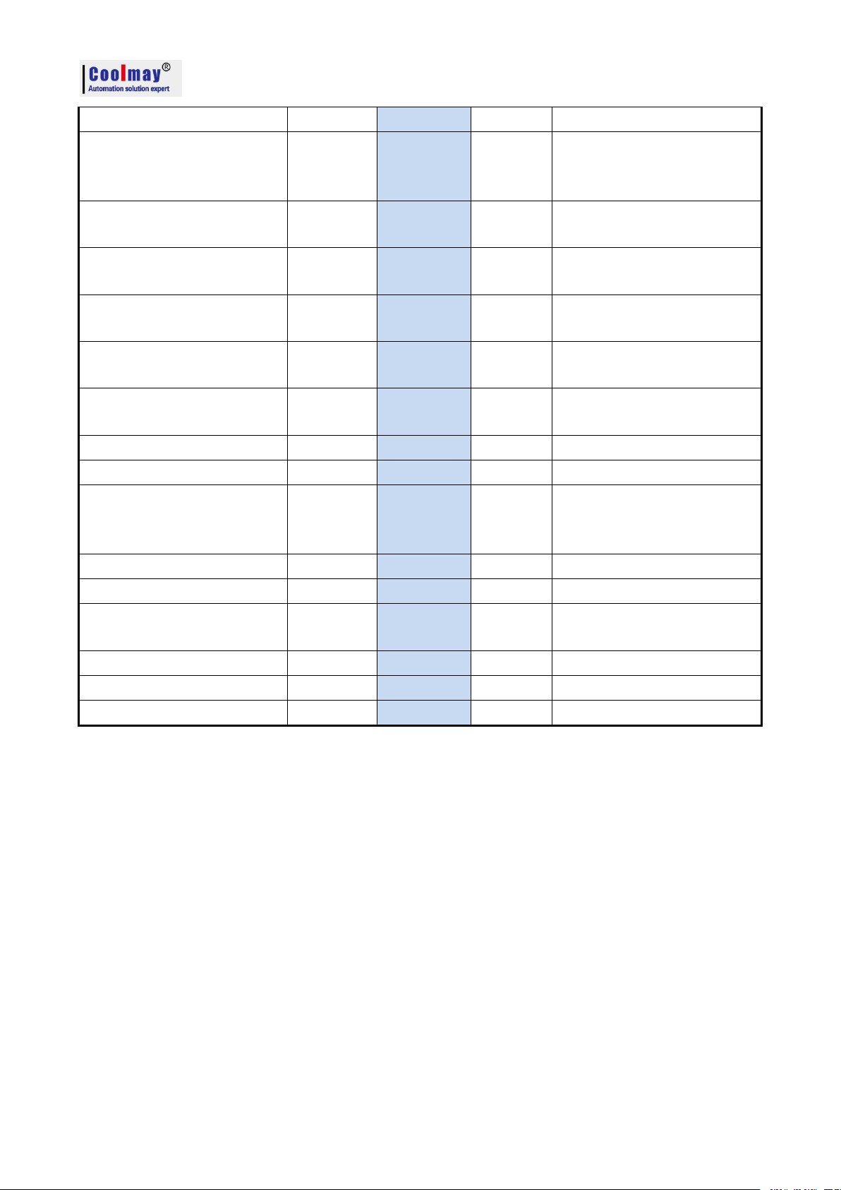
CX3G/FX3GC PLC Programming manual
differentiation
RS command CAN
master-slave
-
-
M8426
M8426=0 master-slave mode,
M8426=1 multi-device
mode
RS command end
operation settings
012
MODBUS RTU function
M8196=1
M8125=1
M8192=1
-
RD3A\WR3A receiving
completion
M8128
M8408
M8428
Need manual reset
RD3A\WR3A
communication over-time
M8129
M8409
M8429
Need manual reset
ADPRW command
completion mark
M8029
M8029
M8029
Command execution end
mark
Communication parameters
D8120
D8400
D8420
Communication mode
-
D8401
D8421
Master-slave station number
D8121
D8414
D8434
D8440
D8442
D8434:CAN slave station NO
D8440\D8442 multi-device
mode ID NO
RD3A/WR3A overtime
D8129
D8409
D8429
Unit: ms
RD3A/WR3A interval period
D8126
D8406
D8426
26232 or higher version
RD3A\WR3A end
operation -1
012
ADPRW command settings
D8126=0
D8126=1
D8126=2
26232 or lower version
ADPRW command settings
D8397=0
D8397=1
D8397=2
26232 or higher version
CAN data frame
-
-
M8427
M8192:the activation mark of using programming port protocol and other protocol. (26232 and
higher version is power lost not retentive)
M8402:Send mark (use when RS2 command).
M8403:Communication completion mark (communication completion flag when using RS
command, needs manual reset).
M8404: Data is receiving.
M8408:Communication completion mak (Valid while using ADPRW command and needs manual
reset).
M8409: Communication time out.
M8029: Communication completion mark (communication completion mark while using ADPRW
instruction and needs manual reset).
M8161: 8-bit/16-bit mode distinguishing mark for RS/RS2 command (version 26230 and above,
always in 8-bit mode)
D8400: Save the communication parameters of the Modbus RTU protocol
D8401: Save the communication mode of serial port 3. D8401=H11 represents PLC as Slave.
D8401=H1 represents PLC as Master; D8401=H0 represents the RS free communication mode.
D8406: Interval period. Default as 12 times.
46
Page 49
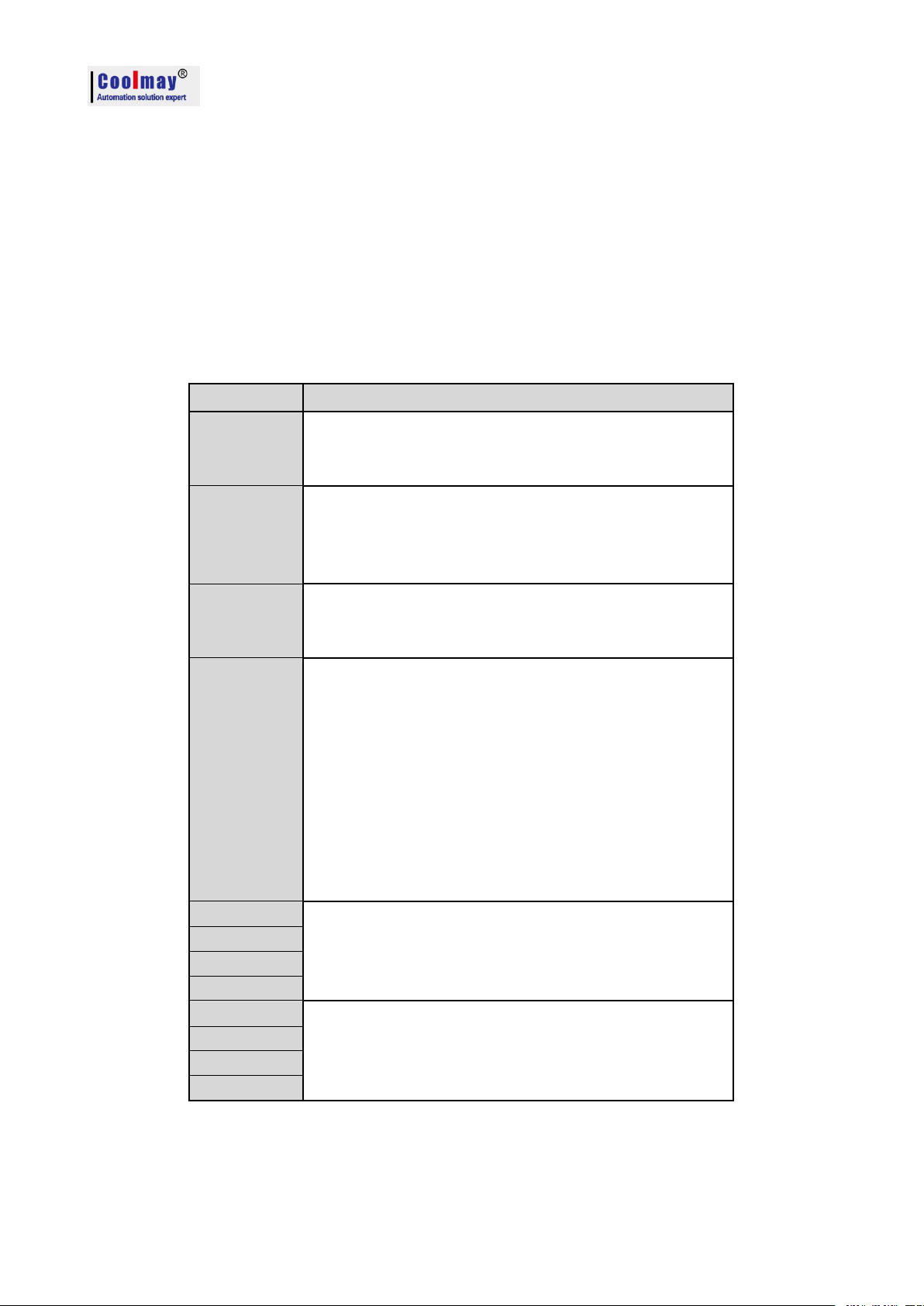
CX3G/FX3GC PLC Programming manual
Bit number
Content
b0
Data length
0:7 bit
1:8 bit
b2
b1
Parity
00:None
01:Odd
11:Even
b3
Stop bit
0:1 bit
1:2 bit
b4
b5
b6
b7
Baud rate (b7b6b5b4)
0100:600bps
0101:1200bps
0110:2400bps
0111:4800bps
1000:9600bps
1001:19200bps
1010:38400bps
1011:57600bps
1101:115200bps
b8
Unavailable, Set 0
b9
b10
b11
b12
Unavailable, Set 0
b13
b14
b15
D8409: Time-out period. (Unit: ms. Better not over 100ms while setting.)
D8414: Save the master or slave station number (The value mast be set as max K255 as master).
D8126: When using the serial port 3 in the ADPRW instruction, set D8126 to 1. (26232 or lower
version)
D8397: When using the serial port 3 in the ADPRW instruction, set D8397 to 1. (26232 and higher
version)
Support RS2,WR3A,RD3A,ADPRW commands. Can be set in parameter zone, correspond to serial
port 3. Parameter zone settings are valid only for this channel. Invalid for serial port 2.
D8400 Parameter set
47
Page 50

CX3G/FX3GC PLC Programming manual
b0
Select protocol
0: Other communication protocol
1: MODBUS protocol
b1~b3
Unavailable, Set 0
b4
Master/Slave setting
0: MODBUS Master
1: MODBUS Slave
b5~b15
Unavailable, Set 0
D8401 Parameter set
8.3.1 Mitsubishi programming protocol
When using as mitsubishi programming port protocol: set M8192=0.
8.3.2 Mitsubishi programming protocol
When using as mitsubishi free port protocol: set M8192=1, M8402=1;
Program example:
Use the serial port tool to monitor serial port 3 for below data:[2017:11:01:11:49:16][receive]37 38
39
Last parameter of RS2 instruction =0: serial port 2;
=1: Serial port 3;
=2: CAN.
48
Page 51
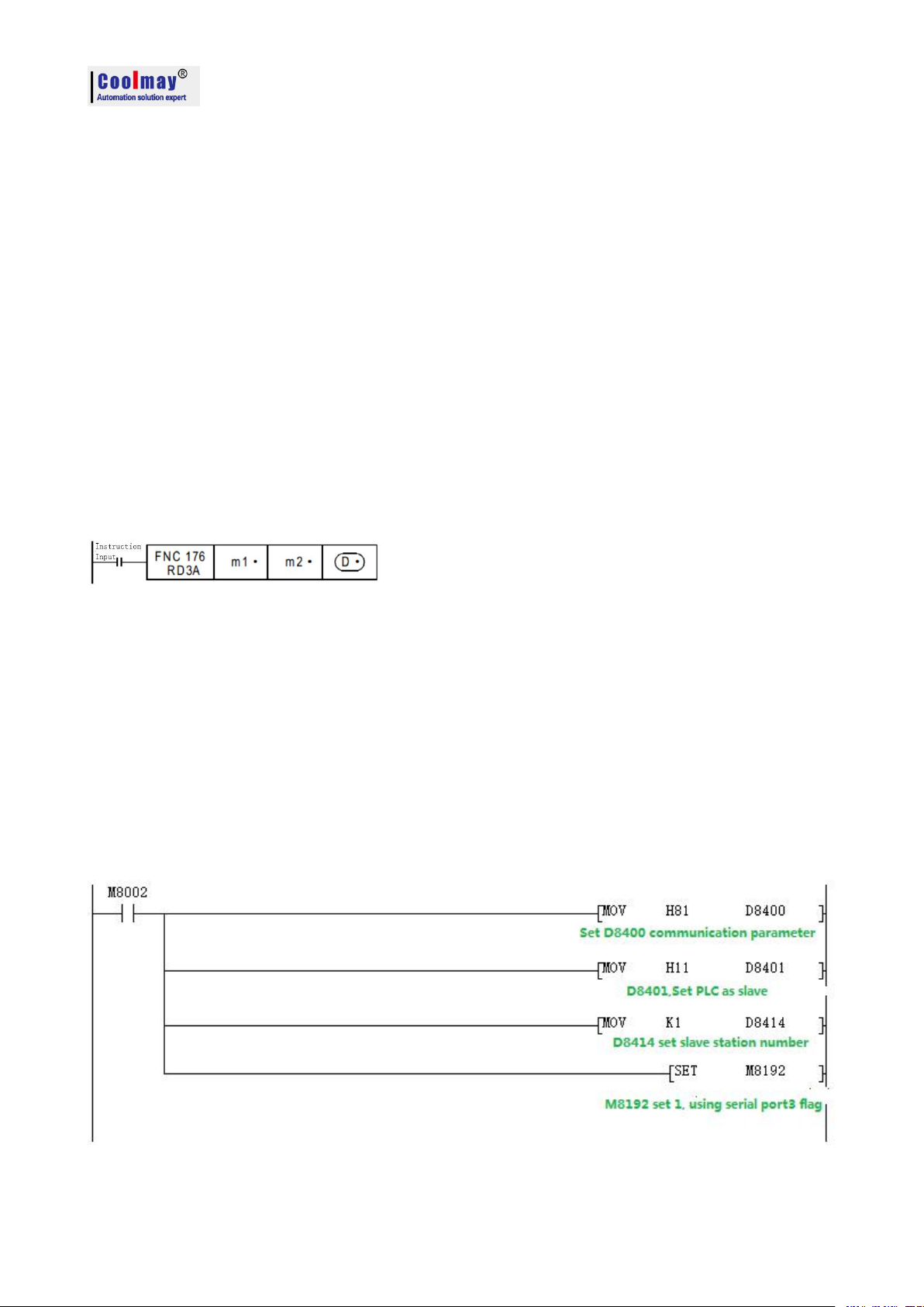
CX3G/FX3GC PLC Programming manual
8.3.3 Modbus RTU protocol RD3A/WR3A command
Used as MOdbus RTU: set M8192=1; set D8400 as communication parameters, set D8414 s as
master slave station no. For example: D8400=H81,D414=K1(communications parameter as
9600/8/n/1,slave station number is 1)
When PLC is as master, ADPRW,RD3A and WR3A is supported.
RD3A and WR3A only support the below MODBUS functions:
Function No. 03: Reads the holding register and takes the current binary value range of 1-32 in one
or more holding registers.
Function No. 06: Load the specific binary value into a holding register (write register) with a range
of one.
Function No. 16: Preset multiple registers, load specific binary values into a series of consecutive
holding registers (write multiple registers), The range is 1-32.
Note: For main version 26231 lower,The RD3A and WR3A must be triggered with a rising edge.
For 26231 version and higher,it can be triggered by the normal signal.
Read slave data instruction function and action description:
RD3A originally referred to the analog module readout.
For CoolMay PLC, the RD3A instruction corresponds to Modbus's No. 03 function.
In the instruction,
m1 represents the station number of the read slave device,range:1-247;
m2 represents the first address number of the read data in the slave device;
D represents the number of registers read, range: 1-32, and the read data is sequentially stored
in the host D.+1, D.+2.
D-1 address value must be set to 0. (=0: serial port 2; =1: serial port 3; =2: CAN)
Program Example:
Slave program:
49
Page 52
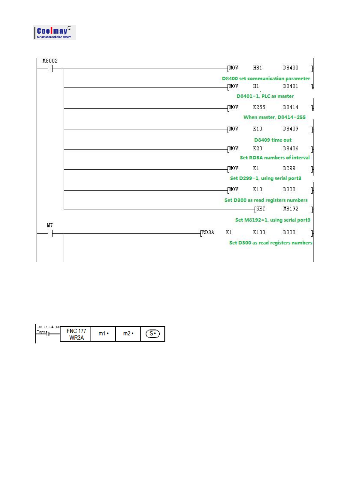
Master program:
CX3G/FX3GC PLC Programming manual
Use the serial port tool to monitor serial port 3 for below data:
[2017:11:01:09:00:11][receive]01 03 00 64 00 0A 84 12
[2017:11:01:09:00:11][receive]01 03 14 00 42 00 4D 00 58 00 58 00 63 00 37 00 2C 00 21 00 16
00 0B 9F C7
Write data to the slave instruction function and action description:
WR3A originally referred to the analog modules write.
For CoolMay PLC, the WR3A instruction corresponds to Modbus's 06 and 10 functions.
In the instruction,
m1 represents the station number of the slave device to be written, range :1-247.
m2 represents the first address number of the write register in the slave device;
S represents the numbers of registers to be written, ranging:1-32. The data to be written is
sequentially stored in the host S.+1, S.+2.
S=1, the WR3A instruction corresponds to the Modbus 06 function.
S=2-247, the WR3A instruction corresponds to the Modbus 10 function.
S.-1 address value must be set to 0. (=0: serial port 2; =1: serial port 3; =2: CAN)
50
Page 53

Program Example
Slave program
Master program
CX3G/FX3GC PLC Programming manual
Use the serial port tool to monitor serial port 3 for below data:
[2017:11:01:09:25:20][receive]01 10 00 64 00 08 10 00 0B 00 16 00 21 00 2C 00 37 00 42 00 4D
00 58 D1 6C
[2017:11:01:09:25:20][receive]01 10 00 64 00 08 10 00 0B 00 16 00 21 00 2C 00 37 00 42 00 4D
00 58 D1 6C
51
Page 54
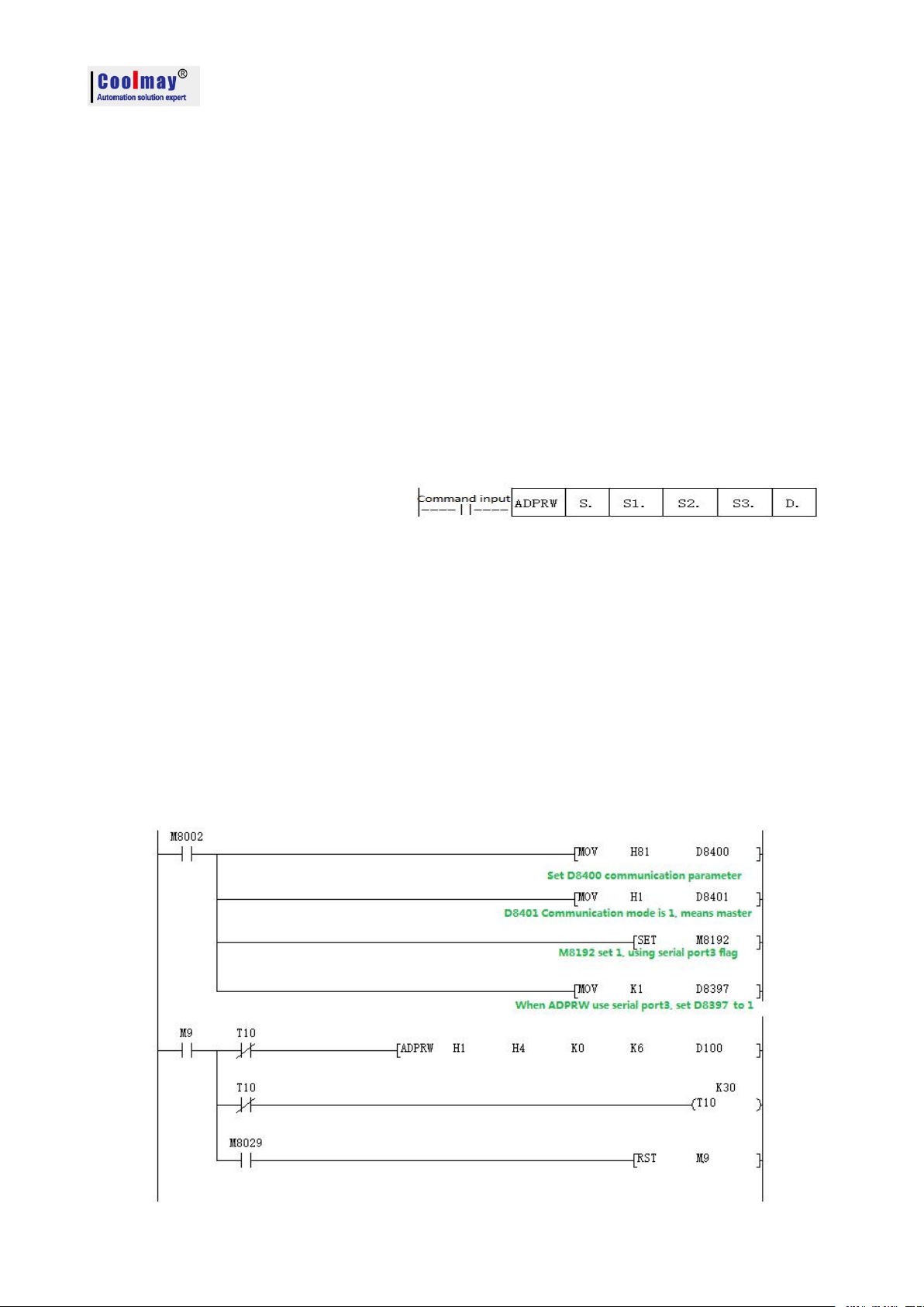
CX3G/FX3GC PLC Programming manual
8.3.4 MODBUS RTU ADPRW Command ADPRW instruction supports all functions of the MODBUS RTU.
No. 01: Read coil status and get the current status (ON/OFF) of a set of logic coils, range 1-512.
No. 02: Read the input status and get the current status (ON/OFF) of a group of switch inputs, range
1-512.
No. 03: Read the retentive register and get the current binary value in one or more retentive
registers, ranging from 1-32.
No. 04: Get the current binary value in one or more input registers, range 1-32.
No. 05: Force a single coil to force the on/off state (write bit) of a logic coil, range 1.
No. 06: Load specific binary values into a holding register (write register), range 1
No. 15: Force multiple coils, forcibly open and close a series of continuous logic coils (write
multiple bits), range 1-512.
No. 16: Preset multiple registers, load specific binary values into a series of consecutive holding
registers (write multiple registers), range 1-32.
ADPRW function and action description:
S. indicates the station number of the slave device being read and written, the range is 0-247;
S1. indicates the function code (that is, the functions 01-06, 15, and 16 written above);
S2. The function parameter corresponding to each function code (the operand indicates the
MODBUS start address when the function is 01);
S3. The function parameters corresponding to each function code (the operand indicates the number
of access points when the function is 01, and the parameter is fixed to 0 when the 05 function is
used);
indicates the starting position of the data storage device.
04 register input readout.
Program Example
Master program
52
Page 55

Slave program
MODBUS device
CX3G/FX3GC device
Input (readout
dedicated)
Coil (read/write)
0x0000~0x1DFF
0x0000~0x1DFF
M0~M7679
0x1E00~0x1FFF
0x1E00~0x1FFF
M8000~M8511
0x2000~0x2FFF
0x2000~0x2FFF
S0~S4095
0x3000~0x313F
0x3000~0x313F
TS0~TS319
0x3140~0x31FF
0x3140~0x31FF
Unused address
0x3200~0x32FF
0x3200~0x32FF
CS0~CS255
0x3300~0x337F
0x3300~0x337F
Y0~Y177
0x3380~0x33FF
-
Unused address
0x3400~0x347F
-
X0~X177
An error occurs when accessing an unused address
CX3G/FX3GC PLC Programming manual
Use the serial port tool to monitor serial port 3 for below data:
[2017:11:01:17:38:34][receive]01 04 00 00 00 06 70 08
[2017:11:01:17:38:34][receive]01 04 0C 00 15 00 20 00 2B 00 41 00 57 00 00 5F A7
8.4 Modbus Communication address number
8.4.1 Bit device:
53
Page 56
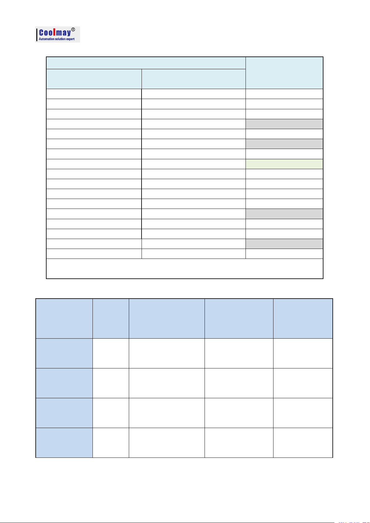
8.4.2 Word device:
MODBUS device
CX3G/FX3GC device
Input register (readout
dedicated)
Holding register (read/write)
0x0000~0x1F3F
0x0000~0x1F3F
D0~D7999
0x1F40~0x213F
0x1F40~0x213F
D8000~D8511
0x2140~0x7EFF
0x2140~0x7EFF
R0~R23999
0x7F00~0xA13F
0x7F00~0xA13F
Unused address
0xA140~0xA27F
0xA140~0xA27F
TN0~TN319
0xA280~0xA33F
0xA280~0xA33F
Unused address
0xA340~0xA407
0xA340~0xA407
CN0~CN199
0xA408~0xA477
0xA408~0xA477
CN200~CN255
0xA478~0xA657
0xA478~0xA657
M0~M7679
0xA658~0xA677
0xA658~0xA677
M8000~M8511
0xA678~0xA777
0xA678~0xA777
S0~S4095
0xA778~0xA78B
0xA778~0xA78B
TS0~TS319
0xA78C~0xA797
0xA78C~0xA797
Unused address
0xA798~0xA7A7
0xA798~0xA7A7
CS0~CS255
0xA7A8~0xA7AF
0xA7A8~0xA7AF
Y0~Y177
0xA7B0~0xA7B7
-
Unused address
0xA7B8~0xA7BF
-
X0~X177
An error occurs when accessing an unused address
CN200~255 is a 32-bit counter
Operand function
S1.
Function
code
S2.
MODBUS
address/subfunction
code
S3.
Access
points/subfunction
data
D.
Data storage
device start
Coil readout
1H
MODBUS
Address:
0000H~FFFFH
Access points:
1~2000
Read object device
D.R.M.Y.S
Input readout
2H
MODBUS
Address:
0000H~FFFFH
Access points:
1~2000
Read object device
D.R.M.Y.S
Holding register
readout
3H
MODBUS
Address:
0000H~FFFFH
Access points:
1~125
Read object device
D.R
Input register
readout
4H
MODBUS
Address:
0000H~FFFFH
Access points:
1~125
Read object device
D.R
CX3G/FX3GC PLC Programming manual
8.4.3 ADPRW Command function parameter
54
Page 57
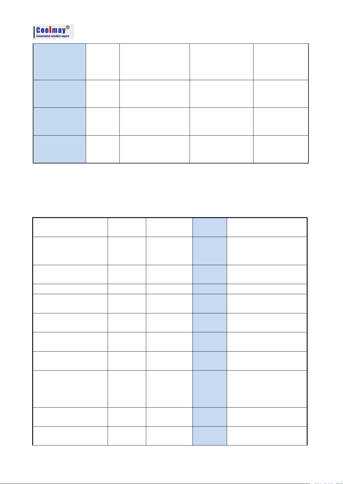
Single coil write
5H
MODBUS
Address:
0000H~FFFFH
0(Fix)
Write object device
D.R.X.Y.M.S
0=OFF
1=ON
Single register
write
6H
MODBUS
Address:
0000H~FFFFH
0(Fix)
Write object device
D.R
Bulk coil writing
FH
MODBUS
Address:
0000H~FFFFH
Access points:
1~1968
Write object device
D.R.X.Y.M.S
Bulk register write
10H
MODBUS
Address:
0000H~FFFFH
Access points:
1~123
Write object device
D.R
8.5 CAN communication port
Functions
Serial port
2(A/B)
Serial port
3(A1/B1)
CAN(H/L)
Remark
Programming port
M8196=0
M8192=0
-
26232 or higher version:
power lost can not be
retentive
RS2 functions
M8196=1
M8125=0
M8192=1
-
RS2 sending mark
M8122=1
M8402=1
M8422=1
Need manual reset
RS2 sending completion
mark
-
-
M8425
Need manual reset
RS2 receiving completion
mark
M8123
M8403
M8423
Need manual reset
RS2 receiving process
mark
M8124
M8404
M8424
Data is receiving
RS command 8/16 bits
differentiation mark
M8161
M8161
M8161
RS2 command CAN
master-slave mark
-
-
M8426
M8426=0 master-slave
mode,
M8426=1 multi-device
mode
RS2 command end
operation settings
012
MODBUS RTU function
M8196=1
M8125=1
M8192=1
-
Support RS2 protocol and MODBUS RTU protocol
The special relays and registers related are as below.
CX3G/FX3GC PLC Programming manual
55
Page 58

CX3G/FX3GC PLC Programming manual
RD3A\WR3A receiving
completion mark
M8128
M8408
M8428
Need manual reset
RD3A\WR3A
communication
over-time mark
M8129
M8409
M8429
Need manual reset
ADPRW command
completion mark
M8029
M8029
M8029
Command execution end
mark
Communication
parameters
D8120
D8400
D8420
Communication mode
-
D8401
D8421
Master-slave station
number
D8121
D8414
D8434
D8440
D8442
D8434:CAN slave station
NO
D8440\D8442 multi-device
mode ID NO
RD3A/WR3A time-out
period
D8129
D8409
D8429
Unit: ms
RD3A/WR3A interval
period
D8126
D8406
D8426
26232 or higher version
RD3A\WR3A end
operation -1
012
ADPRW command
settings
D8126=0
D8126=1
D8126=2
26232 or lower version
ADPRW command
settings
D8397=0
D8397=1
D8397=2
26232 or higher version
CAN data frame
-
-
M8427
M8422: Send data and needs manual reset.
M8423: Date receiving completion.
M8424: Data is under receiving.
M8425: The transmission is completed and needs manual reset.
M8426: Switch between multi-machine mode and master-slave mode
M8426=1: CAN is in multi-machine mode, there is no master-slave division, and it can
transmit up to 8 bytes of data.
M8426=0: CAN is the master-slave mode. There must be one master on the bus line,
which is similar to the MODBUS function.
M8427: =0 means setting as CAN2.OB extension frame. =1 means setting as CAN2.OA
standard frame.
M8428: Set as ON while right response of MODBUS communication and needs manual reset.
M8429: Communication times out.
D8420:Communication parameters.
D8420: The 0th to 9th bits are CAN baud rate, 1K~1023K. The default is 500.
Supported baud rate:5 10 15 20 25 40 50 62 80 100 125 200 250 400 500 666 800 1000.
D8421: Communication protocol and description of master-slave station.
56
Page 59

CX3G/FX3GC PLC Programming manual
1) Support RS2 instruction
2) Support WR3A,RD3A instruction.
3) Support ADPRW instruction
RS2 command: Setting as D8421=H10, which means RS protocol.
RD3A, WR3A, ADPRW command: D8421=H1 is master station, D8421=H10 is slave station.
D8126: When using the ADPRW instruction, set the D8126 to 2 when using CAN. (lower than
26232 version)
D8397: When using the ADPRW instruction, set the D8397 to 2 when using CAN. (versions
26232 and above)
D8426: Interval period. Default as 12 times.
D8429: Time-out period.
D8434: Slave station number.
D8440: Save the local ID number (slave station number).
D8442: When multiplexed, save the slave ID number (the slave what data is read).
RS2 finial parameter =0: serial port 2;
=1: serial port 3;
=2: CAN
When RS2 support CAN, multiple channels can communicate with each other, ID(read 29
bit )=D8442;ID(write 29 bit)=D8440,at most 8 length.
29 digits indicate that the first three are useless. Multi-channel interconnection example:
LD M8000 RS2 D600 K8 D800 K8 K2
LD M8002 MOV H10 D8421
LDI M8422 ANI M8424 SET M8422
For specific operation explanation, please refer to WR3A and RD3A instructions of serial port 2
or serial port 3
S.-1 address value must be set to 2. (=0: serial port 2; =1: serial port 3; =2: CAN)
( Set D8126=2 Corresponds to optional CAN port)
For example, CAN port program of expansion board
LD M8002 MOV H1 D8421:CAN port of this PLC is the master station
LD M8000 MOV K2 D8126
LD M8 ADPRW H1 H2 H2000 K16 M100
It means that the CAN port of the PLC communicates with the CAN port of the slave PLC, and
reads 16-bit S0~S15 of the slave PLC to the M100~M115 of the master PLC.
The default state is compatible with Mitsubishi original programs. The Mitsubishi PLC only has
one port to support the ADPRW instruction, depends on D8401 (in prior) and D8421. All three ports
of Coolmay PLC support the ADPRW instruction.
57
Page 60

CX3G/FX3GC PLC Programming manual
Functions
Network
Remark
Network preparation
M8193
Write network address
M8197
26232 or higher version
MODBUS time out
M8062
IP address conflict
M8063
Switch mark between Mitsubishi
functions and MODBUS
D8395
ADPRW command settings
D8397=3
Router address
R23800 R23801
Mask address
R23802 R23803
MAC address
R23804~R23806
Local IP address
R23807 R23808
Target IP address
R23810 R23811
Terminal
R23812
Default as 502
RD3A/WR3A command cycling times
R23813
MODBUS time-out period
R23814
InfoPacketSend
R23815
26235 and higher version
InfoPacketReceive
R23816
26235 and higher version
8.6 Network communication
Automatically detect the network after power-on. M8193=1 when there is a network chip,
network preparation.
Special relays, registers and registers that IP addresses used are as below.
M8193:=1 Represents that there is a network chip, network preparation
M8197:=1 Write network address, automatic reset (Not support 26231 version, you can write
the above parameters and then restart).
M8062:=1 Represents MODBUS timeout, MODBUS_TCP is used.
M8063:=1 Represents IP address is conflict.
D8395:Switch between Mitsubishi function and MODBUS_TCP
D8395=0:Mitsubishi function
D8395=1:MODBUS_UPD Slave
D8395=2:MODBUS_UPD Master
D8395=3:MODBUS_TCP Slave
D8395=4:MODBUS_TCP Master
D8397:While using ADPRW command, it needs to set D8397 to 3 when using
MODBUS_TCP.(26232 and higher version)
R23800,23801 is the router address. Default:192 .168. 1 .1. Namely R23800=0XC0A8,
R23801=0X0101.
R23802,23803 is the mask address,Default:0 .0. 0 .0. Namely R23802=0,R23803=0。
R23804~23806 is the MAC address,is generated by the system, basically no duplication,can
58
Page 61

CX3G/FX3GC PLC Programming manual
also be set. Note: MAC addresses on the same network cannot be duplicated, otherwise
communication will be abnormal.
R23807,R23808 is the local IP address. Default:192 .168. 1 .250.Namely R23807=0XC0A8,
R23808=0X01FA.
R23810,R23811 is the MODBUS target IP,
R23812 Port default =502
R23813 default=100 (Cycle numbers) is the WR3A RD3A sequential execution interval.
R23814 default=20(200ms), is the MODBUS timeout setting, only retry twice, each time =
( R23814 * 5) ms.
R23815 is MODBUS InfoPacketSend. (26235 and higher version)
R23816 is MODBUS InfoPacketReceive. (26235 and higher version)
1,The master station supports WR3A and RD3A instruction.
For specific operation explanation, please refer to WR3A and RD3A instructions of serial
port 2 or serial port 3
S.-1 address value must be set to 3. (=0: serial port 2; =1: serial port 3; =2: CAN; =3: MODBUS)
For example: WR3A D300 D400 D500,RD3A D300 D400 D500. The S.-1 address value
must be set to 3, Namely D499=3.
D499=0, It is serial port 2 MODBUS.
D499=1, It is serial port 3 MODBUS.
D499=2, It is CAN_MODBUS.
D499=3, It is Network MODBUS.
The slave response function code does not support 0X7 0X8 0XB 0XC 0X11, all others are
supported.
Currently the 26231 version has only 600 (GM_80)
59
 Loading...