

Page 1

Coolmay Multi-channel temperature
control module CM-4TM
User Manual
Shenzhen coolmay Technology Co. Ltd
Page 2

Contents
Introduction to use the manual
Descriptions of symbols in the communication manual
Safety Instructions
Operation Precautions
....................................................................................................
............................................................................................
Chapter 1 Product Introduction
1.1 Characters
1.2 Components and accessories
1.3 Components and features
1.3.1 Front
1.3.2 Bottom - wiring part
.....................................................................................................................
........................................................................................................................................
...............................................................................................................
Chapter 2 Product Specifications
2.1 Specification
.................................................................................................................
..............................................................................
.................................
..........................................................................
.................................................................................
.........................................................................................
......................................................................
Chapter 3 Wiring diagram and module connection diagram
3.1 Wiring diagram -front view
........................................................................................
......................
I
I
II
III
1
1
2
3
3
4
5
5
7
7
3.2 Wiring precautions
3.2.1 Sensor connection
3.2.2 Power connection
3.2.3 Communication connection
3.3 Preparation and start
3.3.1 Overall sequence of operations
3.3.2 Set value status when power-on
......................................................................................................
................................................................................................................
.................................................................................................................
.................................................................................................
..................................................................................................
..........................................................................................
........................................................................................
Chapter 4 Parameter settings and functions
4.1 Input
4.1.1 Input type and temperature range
4.1.2 Input type setting
4.1.3 Input sensor temperature unit setting
4.1.4 Input deviation correction setting
4.1.5 Input digital filter setting
4.1.6 SV Upper/lower limit setting
4.2 Control output
4.2.1 Control output operation setting
4.2.2 MV Upper/lower limit setting
4.2.3 Slope setting
4.2.4 Automatic/manual control settings
..............................................................................................................................
....................................................................................
.................................................................................................................
..............................................................................
......................................................................................
.....................................................................................................
...........................................................................................
............................................................................................................
.......................................................................................
.............................................................................................
........................................................................................................................
...................................................................................
................................................
8
8
9
9
9
9
9
28
28
28
29
29
30
30
31
32
32
34
35
36
4.3 Temperature control
.................................................................................................
38
Page 3

4.3.1 Temperature control method setting
4.3.2 ON/OFF control
4.3.3 PID control
4.3.4 Self-tuning
...................................................................................................................
...........................................................................................................................
............................................................................................................................
................................................................................
38
38
39
41
4.4 Communication
4.4.1 Communication address setting
4.4.2 Communication speed setting
4.4.3 Communication Parity Bit Setting
4.4.4 Communication stop bit setting
4.4.5 Communication response waiting time setting
4.4.6 Enabling/Disabling Communication Write Settings
4.5 Additional features
4.5.1 Monitoring function
4.5.2 Run/Stop Settings
4.5.3 Multi-segment SV
4.5.4 Error Detection Function
4.5.5 Parameter initialization functions
Chapter 5 Troubleshooting method
5.1 error display
..........................................................................................................
.......................................................................................
..........................................................................................
.....................................................................................
........................................................................................
....................................................................................................
.............................................................................................................
...............................................................................................................
................................................................................................................
....................................................................................................
......................................................................................
................................................................
................................................................................................................
5.2 Communication troubleshooting method
5.3 Control troubleshooting methods
........................................................................
...............................................................
.......................................................
...........................................................
43
43
44
45
45
45
46
46
46
47
47
48
49
51
51
51
52
Chapter 6 Modbus RTU protocol
6.1 Read coil status (Func 01-01H)
6.2 Read Input Status (Func 02-02H)
6.3 Read hold memory (Func 03-03H)
6.4 Read input memory(Func 04-04H
6.5 Preset a single memory(Func 06-06H
6.6 Preset multiple memories(Func 16-10H
6.7 Exception response - error code
Chapter 7 Modbus mapping table
7.1 Read coil status / force single coil(Func: 01/05,RW:R/W
7.2 Read input status(Func: 02,RW:R
7.3 Read input memory(Func: 04,RW:R
7.4 Read input memory(Func: 04,RW:R
......................................................................
..............................................................................
..........................................................................
........................................................................
...................................................................
)
...........................................................
)
.......................................................
)
...........................................................................
....................................................................
......................
)
...............................................................
)
...........................................................
)
...........................................................
)
7.5 Read Hold Memory (Func 03) / Preset Single Memory ( Func 06) / Preset
Multiple Memory ( Func 16)
7.5.1 Monitoring function [ Func: 03/06/16, RW: R/W]
...........................................................................................
.........................................................
53
53
54
55
57
58
59
60
62
62
62
63
64
65
65
Page 4

7.5.2 Operation (control operation) function (Func: 03/06/16, RW: R/W)
7.5.3 Master output function (Func: 03/06/16, RW: R/W)
7.5.4 Initial setting function (Func: 03/06/16, RW: R/W)
7.5.5 Set the master output function (Func: 03/06/16, RW: R/W)
7.5.6 Setting options (communication settings) function (Func: 03/06/16, RW: R/W).70
....................................................
......................................................
.........................
...................................
65
66
67
69
Page 5
Thank you for purchasing Coolmay products.
Symbol
Description
Special function supplement.
Warning sign, failure to follow this warning may
result in accident or death
Attention signs, failure to follow this warning
may result in malfunction or product damage
Related function use examples
※
1
comment mark
This user manual includes the instructions and methods of the product. Please
read it before using.
Introduction to use the manual
◆
Please read carefully before using the product
◆
The purpose of this manual is to introduce the functions of this product in detail, and
is not responsible for other purposes..
◆
This manual can not be edited or copied without authorization.
◆
This manual is not included with the product. Please download it from our website
www.coolmay.com
◆
The contents of this manual may differ due to product changes or other reasons
without prior notice.
◆
Please leave us messages if you have any suggestions for this manual.
Descriptions of symbols in the communication manual
I
Page 6

Safety Instructions
Warning sign, failure to follow this warning may
result in accident or death
Caution signs, failure to follow this warning may
result in malfunction or product damage
Following these safety precautions ensures safe and correct use of the product and
helps prevent accidents and reduce risk.
Safety instructions are divided into two categories: warning and caution:
◆ When using large instruments (such as nuclear power, medical machinery,
surveying, railway, aviation, combustion equipment, entertainment machinery, etc.,
including safety facilities) that have an impact on life or property, please make sure to
perform double safety measures before using. Otherwise, fire, life-threatening, property
damage may occur.
◆ Installed on the panel, otherwise it may cause electric shock.
◆ Make sure to disconnect the power supply while checking or repairing, otherwise it
may cause electric shock.
◆ Please check the polarity of the power supply before powering up, otherwise it may
cause fire.
◆ Please do not disassemble or modify the product. If you need internal inspection or
repair, please contact our company. Otherwise, it may cause fire, electric shock and
product damage.
◆ Do not use this product outdoors, otherwise may result in short product life or
electric shock.
◆ Use AWG 20 (0.5mm2) or better cable when connecting, otherwise it may cause
fire.
◆ Use this product within the rated specifications, otherwise it may damage the
II
Page 7

product or cause fire.
◆ Do not connect a load that exceeds the rated range, otherwise it may damage the
product or cause fire.
◆ Do not use detergents such as water or oil to clean the product. Wipe it with a dry
towel, otherwise may damage the product or cause fire.
◆ Do not use this product in a place that is flammable, explosive, humid, direct
sunlight, high temperature, strong vibration or shock, otherwise it may cause fire or
explosion hazard.
◆ Do not allow dust or wiring residue to go into the product, as this may cause fire or
damage to the product.
◆ Please check if the polarity of the sensor is connected correctly before using,
otherwise it may cause fire or explosion hazard.
Operation Precautions
Please read the precautions carefully before using, otherwise it may cause damage
to the product or accident.
Power supply voltage and use environment
◆ Use the voltage within the rated range.
◆ Ambient temperature: -10℃
◆ Power on the product for 20 minutes before using.
◆ Install a switch or circuit breaker to control the power supply voltage of the product.
◆ Install the switch or circuit breaker near the product for easy operation.
◆ Please install and use this product in a well ventilated environment, if necessary,
install a cooling fan.
◆ Please use the product in the environment as below.
~
50℃.
Indoor, altitude below 2000m, pollution level 2, installation category II
III
Page 8

Input sensor
◆ If it is unavoidable to avoid the temperature detected by the sensor due to
environmental factors, please use the deviation correction to minimize the error.
◆ When using a thermocouple sensor, please use the compensation wire of the rated
range when extending the wire. Otherwise, the joint between the thermocouple and the
extension wire will be thermally deformed, resulting in inaccurate measurement
temperature.
◆ If using a RTD sensor, connect three terminals and use three cables with the same
material, thickness and length. Otherwise, thermal deformation may occur, resulting in
inaccurate measurement temperature.。
◆ When changing the input sensor, please disconnect the power supply, connect the
new sensor, and then power on the PC to modify the relevant parameters.
◆ Install the filter on the controller. In addition, install the shield wire near the power
supply.
Noise impact
◆ Product power line and high-voltage line are separately routed to prevent impulse
noise interference.
◆ Please try to avoid high frequency noise interference in the environment, such as
welding machine, sewing machine, high-capacity SCR controller and high-capacity motor.
◆ Do not use this product in accessories of high frequency broadcast, TV and wireless
equipment.
Communication
◆ Use twisted pair cable for communication cable and ferrule on both sides of the
cable to reduce external noise interference.
◆ Do not arrange communication cables on the AC power accessories.
◆ Pleease use independent power supply voltage (24VDC) for communication
converter.
IV
Page 9

Chapter 1 Product Introduction
Chapter 1 Product Introduction
1.1 Characters
CM-4TM temperature controller module realized high-speed sampling (cycle: 100ms),
side connection can expand up to 31 modules. It communicates with PC through RS485,
and a variety of convenient and simple functions can achieve precise temperature control.
◆ Up to 124 simultaneous control
◆ Insulation strength per channel - dielectric strength 1,000VAC
◆ Up to 31 modules (124 channels / 62 channels) can be connected. The expansion
modules used do not need additional communication and power supply.
◆ High-speed sampling period: 100ms
◆ Heating/cooling simultaneous control
◆ Sensor status can be monitored by current transformer (CT)
◆ Communicate with PC via RS485 (Modbus RTU)
◆ Connector wiring is convenient for wiring and maintenance: Sensor input interface,
control output interface, power/communication connector use pluggable terminal
◆ Multi-channel inputs / multiple ranges
◆ Applications: Hot runner systems, electronic furnaces, reflow soldering, catapults
and extruders
1
Page 10
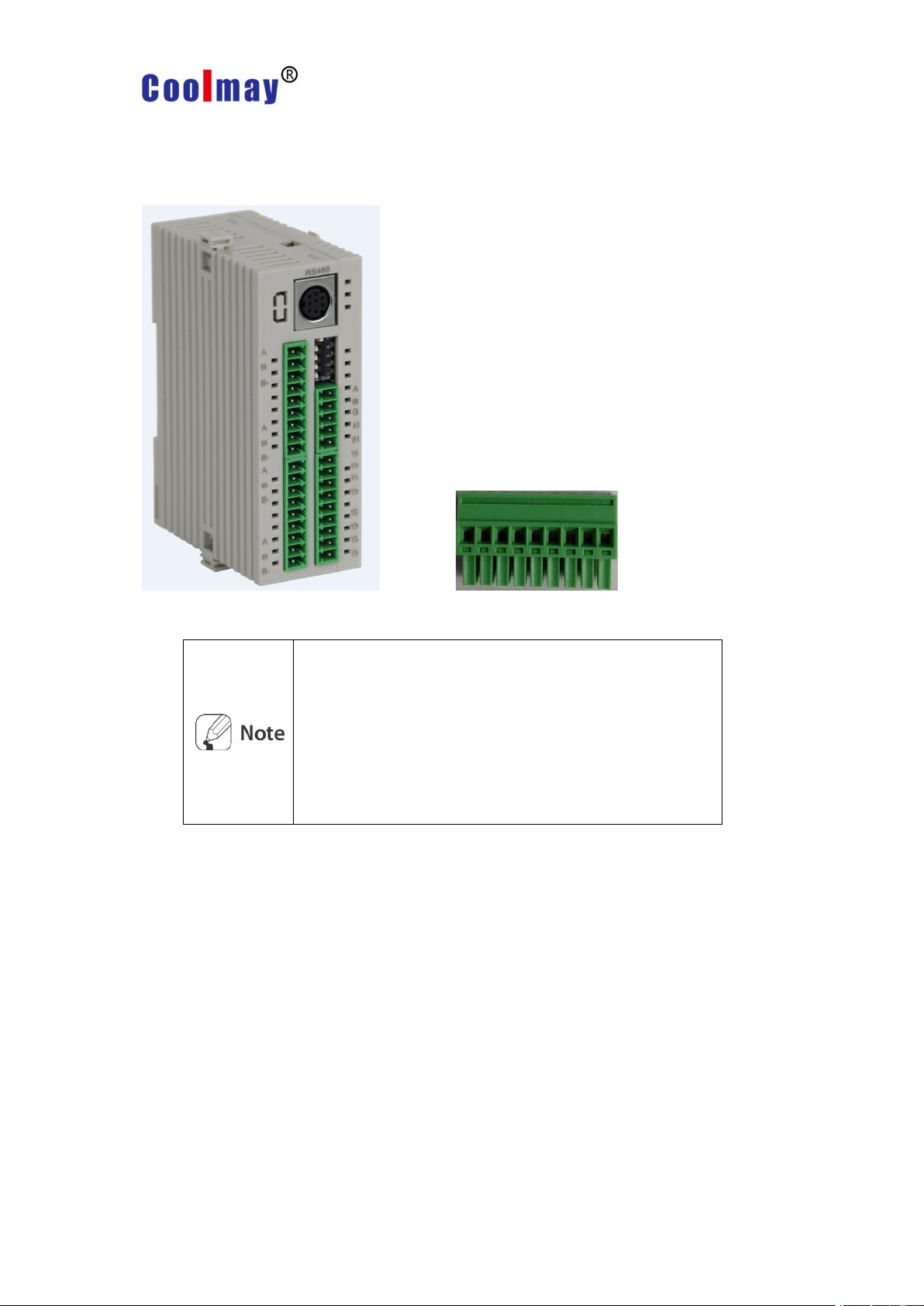
1.2 Components and accessories
Please confirm whether the components are complete after
your purchase. If any defects or damage, please contact the
sales for after-sale services.
Please note that the power/communication connector is only
included in the basic module.
Please visit the official website www.coolmay.com to download
the user manual.
Components
Chapter 1 Product Introduction
Body Terminals
2
Page 11

1.3 Components and features
Status
LED display
Power on
※1
Output
control
Self tuning
※2
Power LED
※3
Green
Green
Green
CH1 LED
2400bps-flicker
ON-red
flicker
CH2 LED
4800bps-flicker
ON-red
flicker
CH3 LED
9600bps-flicker
ON-red
flicker
CH4 LED
19200bps-flicker
ON-red
flicker
38400bps-flicker
1.3.1 Front
Chapter 1 Product Introduction
LED display
※1. After the power is on, the LED indicator will flash once in sequence, then locate the
corresponding frequency with communication speed set earlier. The LED flashes for 5
seconds (cycle: 1 second).
*2. The corresponding LED will flash while self tuning (cycle 1 second).
*3: The power LED flickers while communicating with the outside (cycle 1 second).
3
Page 12

1.3.2 Bottom - wiring part
Chapter 1 Product Introduction
4
Page 13
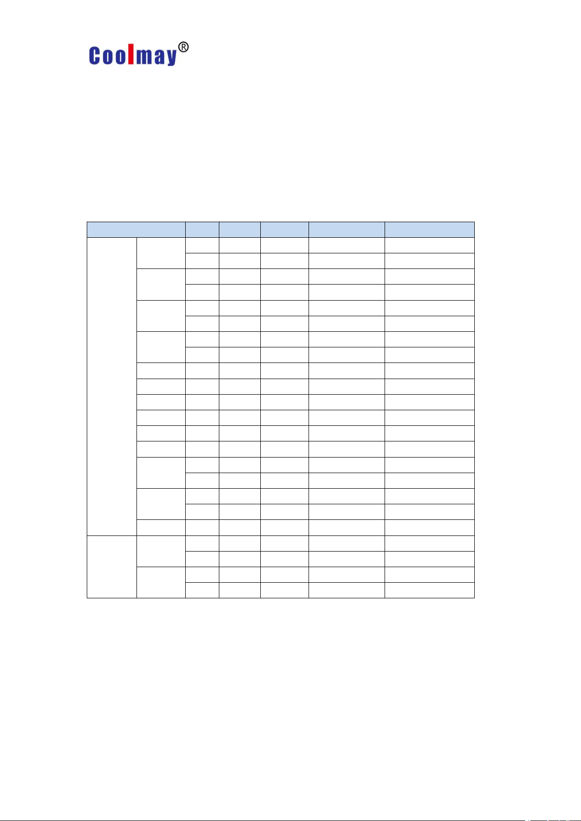
Chapter 2 Product Specifications
Item
CM-4TM
Channels
4 channels----Each channel insulation, dielectric strength1,000VAC
Voltage
24VDC
Voltage range
Nominal voltage * 90% ~ 110%
Power
Max.5W (max load)
Display type
Non-display type - modify parameters and real-time monitoring (PC
or PLC) via external device
Input
RTD
DPt100Ω, JPt100Ω 3 line(resistance: Max. 5Ω)
Thermocou
ple
K, J, E, T, L, N, U, R, S, B, C, G and PLII (13 types)
Display
precision
RTD
(PV±0.5% or ±1℃ greater) < ±1 bit
Thermocou
ple ※1
Temperatur
e effect
※2
RTD
(PV±0.5% or ±2℃ greater) < ±1 bit,
(If thermocouple input, ±5℃ when lower than -100℃ ),
thermocouple L ,U, C, G, R, S, B: (PV±0.5% or ±5℃ greater) < ±1bit
Thermocou
ple
Control
output
Relay
250VAC 3 A 1a
SSR
22VDC ±3V Max.30mA
Communication output
RS485 (Modbus RTU protocol)
Control
mode
Heat, cool
ON/OFF control, P, PI, PD, PID control
Heat & cool
Lag
RTD/thermocouple: 1~100℃/℉(0.1~100.0℃/℉) optional
Proportional band (P)
0.1 ~ 999.9℃
Integral time (I)
0 ~ 9999 sec.
Derivative time (D)
0 ~ 9999 sec.
Control cycle
0.1~120.0 seconds (relay output, SSR drive voltage output type
product)
Hand reset
0.0 ~ 100.0%
Sampling cycle
100ms(4 channels can be sampled simultaneously)
Proof voltage
1000VAC 50/60Hz last 1 minute (between input and power
terminals)
2.1 Specification
Chapter 2 Product Specifications
5
Page 14

Chapter 2 Product Specifications
Item
CM-4TM
Vibration resistance
5 ~ 55Hz (1 minute cycle) amplitude 0.75mm X, Y, Z every direction
2 hours
Relay life
Mechanical
> 10,000,000 times
Electric
> 100,000 times (250VAC 3A resistive load)
Insulation resistance
> 100MΩ (based on 500VDC)
Anti-interface
Interference simulator square wave interference (pulse width 1μs)
±0.5kV
Environmental
temperature
-10 ~ 50℃, Storage: -20 ~ 60℃
Environmental humidity
35 ~ 85%RH, Storage: 35 ~ 85%RH
Attachments
Expansion connector
Power/communication connector [Basic Module only]
Insulation type
Double or reinforced insulation (dielectric strength between the input
and power sections: 1kV)
Certificate
CE, UL
Weight
Approx. 135 ~ 152g
Model
Weight
CM-4TM
Approx. 130g
*1. Thermocouples K, T, N, J, E are below -100 °C and L, U, Platinel II: ±2 °C ± 1 or less. When
the thermocouple B is below 400 °C, the detection accuracy cannot be guaranteed. When R, S
is below 200 °C, it is equal to C, G: 3 °C ± 1 or less.
*2. It is suitable for the situation beyond normal temperature (23 °C ± 5 °C).
Net weight of product refers to the table below.
6
Page 15
Chapter 3 Wiring diagram and module connection diagram
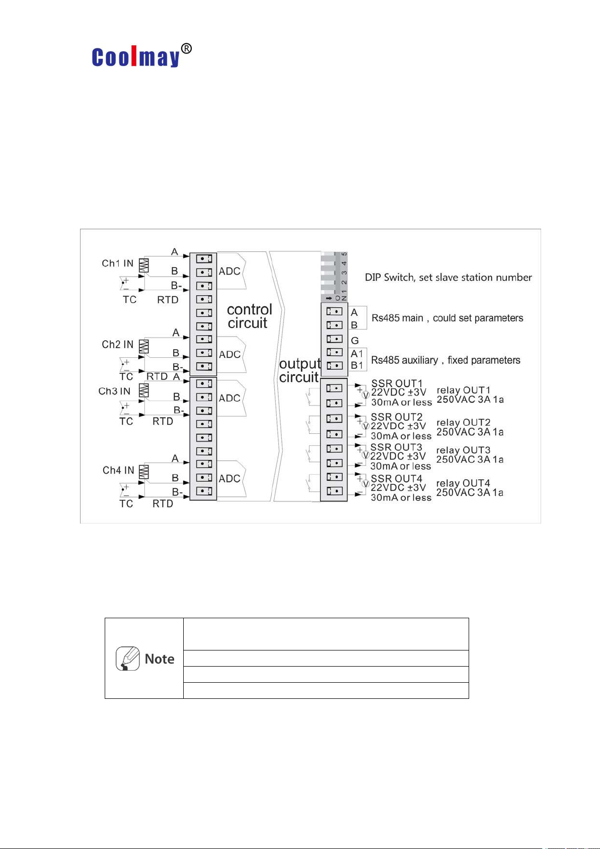
Connecting the power/communication terminals,notice the
polarity of the terminals.
Use AWG 28-16 wires for sensors or compensation wires.
When SSR output, recommend AWG 24 and above cables.
When Relay output, recommend AWG 20 and above cables.
Chapter 3 Wiring diagram and module
connection diagram
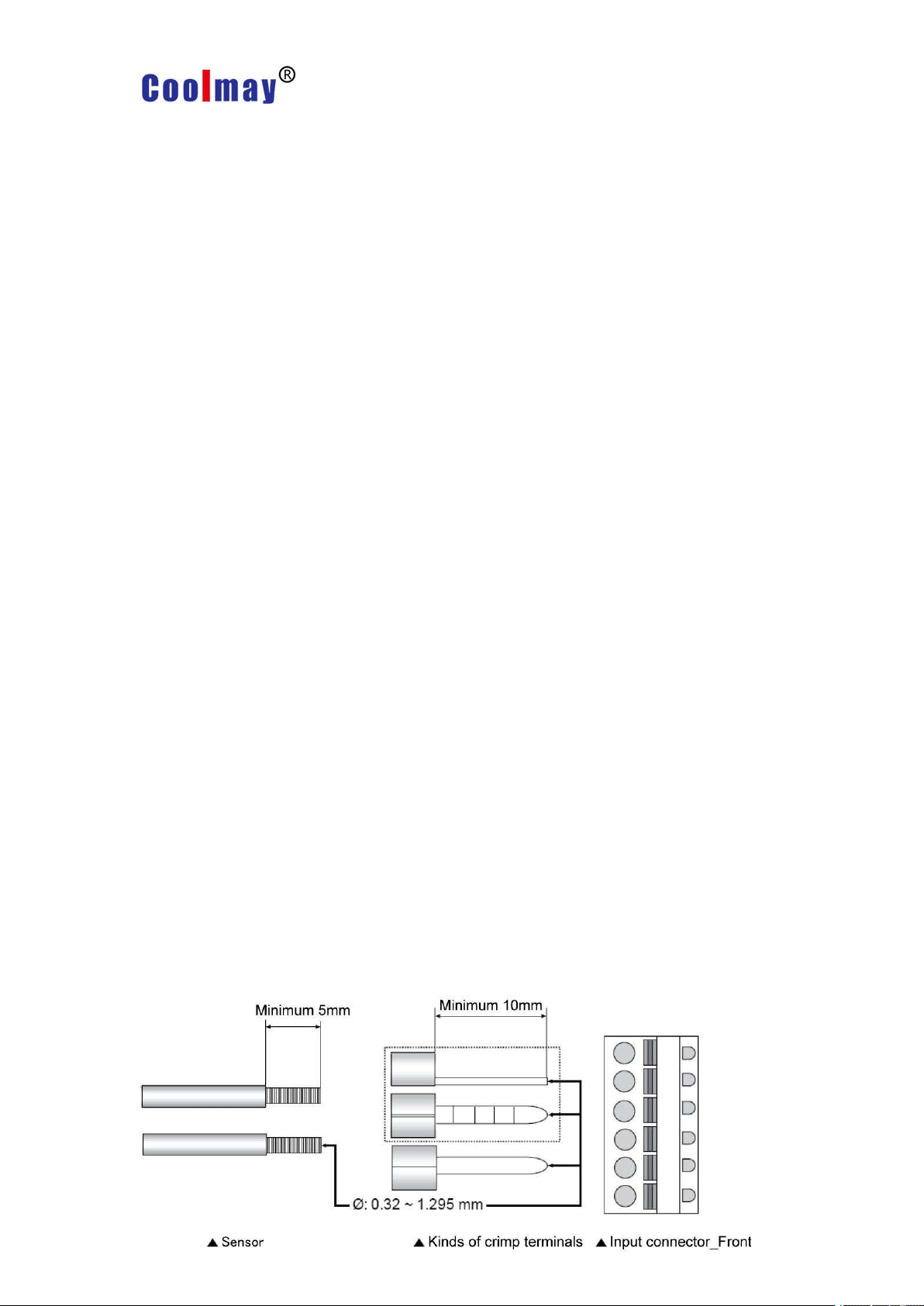
3.1 Wiring diagram -front view
When wiring the thermocouple type, connect B, B-; When wiring the two-wire
resistors, connect A and B; When wiring the three-wire resistor, connect A, B,
B-.
7
Page 16
Chapter 3 Wiring diagram and module connection diagram
3.2 Wiring precautions
◆Incorrect connection of the input terminal and output terminal may result in damage to
the product.
◆Please use the sensor type supported by this product.
◆Make sure the SSR or load is within the rated range.
◆Make sure the communication cable is properly connected to the communication
terminals (A, B).
◆Be sure to connect the polarity (+, -) of the terminal correctly.
3.2.1 Sensor connection
Compensation wire connection
When using a thermocouple sensor, if you extend the wire, use the same size
compensation wire if you use different specifications.
The compensation wire may have a temperature error. Try to choose a
high-performance compensation wire for more accurate temperature measurement.
Measurement error
◆Do not connect the positive and negative polarity of the sensor.
◆Please pay attention to maintain the distance between the load and the sensor.
◆Make sure the sensor is securely connected to the terminal.
AC power wiring
Do not install the sensor near an AC power source.
Input sensor (or compensation wire) connection
8
Page 17

Chapter 3 Wiring diagram and module connection diagram
Make sure the sensor cable is fully inserted into the terminal.
Sensor/crimp terminal connection spec AWG28~16 (DI:
0.32~1.295mm).
Fix the sensor to make the measurement more accurate.
Use AWG 24 ~ 12 specifications for the power cord.
First calculate general power according to the usage and then
connect the corresponding power.
Setting type
Factory
default
Value before
power-on
Value after
power-on
Com address(CH1)※1
auto/ manual
auto
auto
auto
400004(0003H)
manual
manual
Run/stop
Run
Run
Run
400051(0032H)
Stop
Stop
3.2.2 Power connection
Power supply wiring, please refer to 1.3.2 Bottom-power wiring
3.2.3 Communication connection
For the communication connection, please refer to 1.3.1 introduction.
3.3 Preparation and start
3.3.1 Overall sequence of operations
Perform the following steps before operating the CM -4TM for the first time.
1. All external devices, sensors and loads are connected to the CM -4TM terminals.
2. Modify the relevant parameters (PC, GP, etc.) through the external connection device.
3. Load the set parameters into the CM -4TM.
4. After setting the SV value, perform auto-tuning. Use this product after self-tuning.品。
3.3.2 Set value status when power-on
9
Page 18

Chapter 3 Wiring diagram and module connection diagram
PID/ONOFF
PID
PID
Keep presets
ONOFF
Keep presets
MV
0.0
Preset MV
Keep presets
0.0
Stop MV
Keep presets
0.0
Sensor Error MV
Keep presets
※1:The communication addresses involved in this manual are the addresses of
channel 1 (CH1). For the address of channel 2-channel 4, please refer to
Chapters 6 and 7..
10
Page 19
Chapter 4 Parameter settings and functions
28
Input type
No.
Decimal
Parameter
Input range (℃)
Input range (℉)
Thermoco
uple
K(CA)
01K(CA).H
-200 ~ 1350
-328 ~ 2462
1
0.1
K(CA).L
-200.0 ~ 1350.0
-328.0 ~ 2462.0
J(IC)
21J(IC).H
-200 ~ 800
-328 ~ 1472
3
0.1
J(IC).L
-200.0 ~ 800.0
-328.0 ~ 1472.0
E(CR)
41E(CR).H
-200 ~ 800
-328 ~ 1472
5
0.1
E(CR).L
-200.0 ~ 800.0
-328.0 ~1472.0
T(CC)
61T(CC).H
-200 ~ 400
-328 ~ 752
7
0.1
T(CC).L
-200.0 ~ 400.0
-328.0 ~ 752.0
B(PR)81
B(PR)
0 ~ 1800
32 ~ 3272
R(PR)91
R(PR)
0 ~ 1750
32 ~ 3182
S(PR)101
S(PR)
0 ~ 1750
32 ~ 3182
N(NN)111
N(NN)
-200 ~ 1300
-328 ~ 2372
C(TT)※1121C(TT)
0 ~ 2300
32 ~ 4172
G(TT)※2131G(TT)
0 ~ 2300
32 ~ 4172
L(IC)
141L(IC).H
-200 ~ 900
-328 ~ 1652
15
0.1
L(IC).L
-200.0 ~ 900.0
-328.0 ~ 1652.0
U(CC)
161U(CC).H
-200 ~ 400
-328 ~ 752
17
0.1
U(CC).L
-200.0 ~ 400.0
-328.0 ~ 752.0
Platinel II
181PLII
0 ~ 1400
32 ~ 2552
RTD
JPt100 Ω
191JPt100.H
-200 ~ 600
-328 ~ 1112
20
0.1
JPt100 .L
-200.0 ~ 600.0
-328.0 ~ 1112.0
DPt100 Ω
211DPt100.H
-200 ~ 600
-328 ~ 1112
22
0.1
DPt100. L
-200.0 ~ 600.0
-328.0 ~ 1112.0
Chapter 4 Parameter settings and functions
4.1 Input
4.1.1 Input type and temperature range
※1: C(TT): The same temperature sensor as W5 (TT).
※2: G(TT): The same temperature sensor as W(TT).
The sensor feeds the detected temperature back to the thermostat and then controls
the temperature through the thermostat.
SV (set value) is only allowed to be set within the input range.
Page 20

Chapter 4 Parameter settings and functions
29
Parameter
group
Parameter
Setting
range
Factory
default
Unit
Com
address
Initial set
function
CH1 Input type
Refer
to4.1.1
K(CA).H
−
400151(0096H)
When input type is changed, the upper and lower input range will automatically change to the
selected sensor input range, reset these parameters (SV, multi-segment SV setting,
SV-0~SV-3 and input deviation correction are initialized) to ensure that the measurement
environment remains unchanged.
If the measured range is above or below the input range, HHHH (above), LLLL (lower)
will be displayed, and OPEN will be displayed when the sensor is not connected or
disconnected.
Parameter group
Parameter
Setting range
Factory
default
Unit
Com
address
Initial set function
CH1 Temp unit
℃/℉
℃
-
400152(0097H)
When the temperature unit is changed, the input type remains
the same, but SV, multi-segment SV setting, SV-0~SV-3, SV
upper/lower limit and input deviation correction are initialized.
4.1.2 Input type setting
This product supports a variety of sensors, users can choose thermocouple or
thermal resistance according to demand.
Different sensors can be used for each individual channel. Example): CH1 input type
= KCA.H, CH2 input type = JIC.H
4.1.3 Input sensor temperature unit setting
When the input sensor type is set, the temperature unit can be set according to the
actual demand.
Page 21

Chapter 4 Parameter settings and functions
30
Parameter
group
Parameter
Setting range
Factory
default
Unit
Com address
Initial set
function
CH1
Input deviation
-999~999(H)
-999.9
~
999.9(L)
0
bit
400153(0098H
)
For example, the temperature is displayed at 78 ° C,
but the actual temperature is 80 ° C.
In this case, you can set the input deviation value to
2 and the display temperature to 80 °C.
● Make sure the actual temperature detected is correcr,
otherwise it will cause a larger error.
● Most sensors have sensitivity grading, and higher
sensitivity sensors are relatively expensive. Therefore,
most sensors with medium sensitivity measure the
sensitivity difference of each sensor and then set the
input deviation value to ensure more accurate
measurement temperature.
Parameter
group
Parameter
Setting
range
Factory
default
Unit
Communic
ation
address
Initial setting
CH1input digital
0.1~120.0
0.1
Sec
400154(0099H)
4.1.4 Input deviation correction setting
This function is used to correct the deviation caused by the thermocouple and
Thermal resistance sensor, rather than the deviation caused by the product.
The input deviation correction is mainly used when the sensor cannot be directly
connected to the measurement target. This function can be used to correct the resulting
temperature deviation.
4.1.5 Input digital filter setting
This feature allows the product to achieve high-precision temperature control. If the
PV (display value) is not accurate due to noise components, interference, or input signal
instability, the input digital filtering function can be used to achieve more precise
temperature control.
Page 22

Chapter 4 Parameter settings and functions
31
functions
filtering
When the input digital filter is set to 0.4s, the input digital filter will
take 0.4s (400ms) as the sampling period.
When using input digital filtering, the PV (display value) may
differ from the actual measurement.
Parameter group
Parameter
Setting range
Factory
default
Unit
Com address
Default setting
function
SV Lower limit set
See the
explanation
below
-200
℃/
℉
400155(009AH)
SV Upper limit set
1350
400156(009BH)
If the upper/lower limits are set to exceed the sensor range, the set
value
will not be saved and the value before the setting will remain
unchanged.
SV (set value) is valid only in the upper and lower limits of SV.
The SV lower limit does not exceed the SV upper limit.
When the sensor input type is changed, it will be automatically
changed to the sensor temperature range used. The user needs
to reset the upper/lower limit values.
4.1.6 SV Upper/lower limit setting
The SV (set value) can be set to use the upper and lower limits to prevent product
damage or accidents due to excessive or low set temperatures.
* SV lower limit: sensor lower limit range ~ SV upper limit value - 1 bit
* SV upper limit: SV lower limit value + 1 bit ~ sensor upper limit range
Page 23

Chapter 4 Parameter settings and functions
32
Parameter
group
Parameter
Setting range
Factory
default
Unit
Com address
Default
setting
function
CH1
Operating
mode
0:heating 1:cooling
2:heating & cooling
heating
-
400157(009CH
)
Control output operation amount (MV) Control output operation amount(MV)
4.2 Control output
4.2.1 Control output operation setting
General temperature control includes heating, cooling or heating & cooling; heating
control and cooling control are two opposite operations; the PID value will change as the
control object changes.
Heating control
Heating control mode: When PV (display value) is lower than SV (set value), the
output control load (heater) operates.
Cooling control
Cooling control mode: When the PV (display value) is higher than SV (set value), the
output control load (cooler) operates.
Heating & Cooling Control
Heating & Cooling Control: Heating & Cooling controls the same load action.
The heating & cooling mode can control the same object with different PID values,
and can also set the same PID value control.
It is also possible to select the relay output, SSR output or current output depending
Page 24

Chapter 4 Parameter settings and functions
33
Paramet
er group
Associated
parameter
Parame
ter
Setting range
Factory
default
Unit
Communicati
on address
Master
output
functions
PID-PID
PID-ON/OFF
ON/OFF-PID
CH1
dead
zone
- proportional
band ~
+
proportional
band
0.0
bit
400108(006BH)
ON/OFF-ON/OFF
-999 ~ 0 ~ 999
0
If the input is displayed in decimal, the display range is –999.9 ~ 999.9.
When the proportional bands are different, the smaller one takes
precedence.
There is a decimal point when the sensor type (input.H, input.L) is set to
input.L
Cooling load, temperature drop
Cooling output control
temperature
gontrol
l
temperature rises, Heating load
Heating output control
Input sensor (feedback)
on the application (note that only the standard SSR can be used to control the SSR output
in OUT2.
Overlap/dead zone
In heating and cooling control, the SV (setpoint) overlaps between the heating and
cooling dead zones.
According to the SV value, DP is set to a positive value, and there is no control in the
dead zone interval. Therefore, the control operation amount MV is 0 in the dead zone
interval.
The overlap (heating and cooling simultaneous operation) zone is set to a negative
value according
Set to 0 when no overlap/dead zone is used.
Page 25

Chapter 4 Parameter settings and functions
34
Paramet
er
Associated
parameter
parameter
Setting range
Factory
Default
Unit
Com address
Master
output
function
Cooling
Heating
CH1 MV Lower limits
0.0 ~ (MV Upper
0.0
%
400114(0071H)
CH1 MV Upper limits
(MV Lower limits+ 0.1) ~
100.0
100.0
400115(0072H)
Heating&Cooling
CH1 MV Lower limits
-100.0 ~ 0.0
-100.0
%
400114(0071H)
CH1 MV Upper limits
0.0 ~ 100.0
100.0
400115(0072H)
The amount of operation during the self-tuning process
The amount of operation during manual control includes: the amount of operation when
the
control is stopped; the amount of operation when the sensor is faulty; and the initial
amount of operation when the controller is manually controlled.
The upper/lower limit of the MV does not apply to the ON/OFF
mode in standard mode (heating or cooling).
MV Upper limits
MV Upper limits
MV Lower limits
MV Lower limits
Cooling gontrol
<Standard control (heating control)>
<
Heating and cooling control>
4.2.2 MV Upper/lower limit setting
The setting of the MV upper/lower limit limits the amount of operation of the
thermostat, which is beneficial to safety control.
For heating and cooling control, the cooling MV is prefixed with “-”, so the upper
heating limit is controlled to + value and the lower cooling limit is controlled to - value.
Page 26

Chapter 4 Parameter settings and functions
35
Paramete
r group
Parameter
Setting range
Factory
default
Unit
Communicati
on address
Control
operation
CH1 rising slope
setting
0 (OFF) ~ 9999
0
-
400116(0073H)
CH1 falling slope
setting
0 (OFF) ~ 9999
0
-
400117(0074H)
CH1 slope time
unit
0:SEC (s)
1:MIN (m)
2:HOUR (h)
MIN
-
400118(0075H)
For ceramic or ceramic furnaces, heating too fast may
damage the porcelain in the ceramic furnace, and the
slope heating function can achieve slow heating.
When SV (set value) is operated based on the slope setting value based on PV (display value)
and the value of SV or slope is changed, the SV operation amount changes according to the
corresponding change amount.
Determine the SV control object and set the corresponding slope according to the SV variation.
(hereinafter referred to as RAMP SV)
The amount of change in the rise and fall of the slope can be set separately.
The alarm output and slope depend on the SV value.
This function can't be used when the slope is set to 0.
Running Status
Slop
e
Slope function
All modes=0invalid
OPEN, HHHH,LLLL, Autotuning,
Auto>Manual,
RUN>STOP
Arbitrary value
invalid
OPEN, HHHH, LLLL, after Auto-tuning, PV = SV
Arbitrary value
invalid
Power on, SV change, control switch STOP switch to RUN,
Control Switch Manual Switch to Auto, Slope or Slope Time Unit Change
≠0
invalid
4.2.3 Slope setting
The slope is a function related to SV (set value) that prevents the rate of SV from
being limited due to a sudden change (increase or decrease) in the temperature of the
controlled object.
Slope state in different modes
Page 27

Chapter 4 Parameter settings and functions
36
Parameter Group
Associated
parameter
Parameter
Setting range
Factory
default
Unit
Com address
Master
control output
function
PID
CH1 operation
volume
0:Auto-MV:
1:Manual-MV
Auto-MV:
-
400202(00C9H)
Parameter Group
Parameter
Setting range
Factory
Default
Unit
Com address
Monitoring
function
CH1 automatic -
manual control
0: automatic; 1: manual
Auto
-
400004(0003H)
Auto/manual function can be switched freely by controlling the switch.
Auto/manual control remains unchanged when the product is powered down or shut down.
During operation, AT (auto-tuning) can be switched to manual control.
In stop mode, manual control is activated.
If SBA (sensor disconnection alarm) occurs during control, the sensor error operation
amount will be used. In this state, it can be switched to manual control, and the manual
control operation
amount can also be modified.
It is possible to switch to manual/automatic control during control operations.
Priority: Manual Control > Stop > Disconnect (sensor disconnection).
4.2.4 Automatic/manual control settings
Automatic control: When PID control, the operation amount is automatically controlled
according to the SV value. Manual control: In this mode, the user can freely set the
operation amount according to the requirements.
The stop function can be set by setting the digital input terminals (DI1, DI2).
Manual control of the amount of operation
When switching from automatic control to manual control, the initial operation amount
can be set.
AUTO-MV: When switching from manual control to automatic control, the amount of
operation is initialized.
PRESET-MV: Use the set operation amount as the initial value.
Page 28

Chapter 4 Parameter settings and functions
37
Parameter
Group
Associated
parameter
Parameter
Setting range
Factory
default
Unit
Com address
Master contr
ol output fun
ction
Heating, cooling, PID
CH1 Manual operation
Initial operation
0.0 ~ 100.0
0.0
%
400203(00CAH)
Heating&cooling,PID
-100.0 (Cooling) ~
0.0
~ 100.0 (Heating)
0.0
0.1~ -100.0When heating and cooling control, the heating
operation amount is set from
0.1 to 100.0, and the cooling operation amount is set from
0.1 to -100.0.
※ When the power is turned back on after the power is turned off, the operation amount is
controlled to output the value before the power is turned off.
Initial operation amount during manual control
If the manual operation amount is set to PR.MV (manual preset MV), the initial MV can
be manually modified.
Page 29

38
4.3 Temperature control
Parameter
Group
Associated
parameter
Parameter
Setting range
Factory default
Unit
Com address
Initial
setting
function
heating, cooling
CH1
control way
0:PID:1:ON/OFF
0:PID
-
400158(009DH)
heating&cooling
0:PID-PID
1:PID-ON/OFF
2:ON/ OFF-PID
3:ON/OFF- ON/OFF
0:PID-PID
-
Parameter
Group
Associated
parameter
Parameter
Setting
range
Factory
Default
Com address
Master control
output function
Heating
&
Cooling
Heating
CH1 Heating hysteresis
1~100
2
400110(006DH)
CH1 Heating deviation
0~100
0
400111(006EH)
Cooling
CH1 Cooling hysteresis
1~100
2
400112(006FH)
CH1 Cooling deviation
0~100
0
400113(0070H)
4.3.1 Temperature control method setting
The temperature control method can be set by parameters.
4.3.2 ON/OFF control
Chapter 4 Parameter settings and functions
The ON or OFF state is controlled by comparing PV (display value) and SV (set
value).
Hysteresis value setting
When the ON/OFF control output is used, the ON hysteresis and OFF deviation
values can be set.
When the hysteresis value is set too low, it may cause frequent movements and cause
interference (noise, vibration, etc.). In order to reduce interference, the appropriate ON and
OFF offsets are set according to the heating and cooling capacity and thermal
characteristics, the response frequency between the controller and the sensor, the
installation environment and other relevant factors.
Page 30

Chapter 4 Parameter settings and functions
39
Parameter
group
Associated
parameter
Parameter
Setting range
Factory
defualt
Unit
Com address
Master
control output
function
Heating, PID
CH1 Heating
proportional band
0.1 ~
999.9
10
C
400102(0065H)
Cooling, PID
CH1 Cooling
proportional
band
400103(0066H)
Control
Control
(Heating)
(Cooling)
<heating control>
<cooling control>
heating control
4.3.3 PID control
PID is a combination of proportional band (P), integral (I), and differential (D). The
control time is longer than ON/OFF, but the control accuracy is high.
Proportional band (P) control reduces oscillations; integral (I) controls correct for
deviations; and differential (D) controls provide fast response to interference. Through the
combined control of these three, precise temperature control can be achieved.
PID control application
Proportional (P) control: When PID control is selected, the integration and derivative time are set to 0.
Proportional-Integral (PI) Control: When PID control is selected, the derivative time is set to 0.
Proportional-Derivative (PD) Control: When PID control is selected, the integration time is set to 0. When
using the multi-segment SV function, the PID values of SV0 ~ SV3 are the same.
Proportional band settings
When PV (display value) is within the proportional band (P) range, ON/OFF needs to
adjust the proportional period (T), so the time period of proportional control is called the
proportional band.
Page 31

Chapter 4 Parameter settings and functions
40
Parameter
group
Associated
parameter
Parameter
Setting
range
Factory
defualt
Unit
Com address
Master control
output function
Heating, PID
CH1 Heating
integration time
0 ~ 9999
0
Sec.
400104(0067H)
Cooling, PID
CH1 Heating
Integration time
400105(0068H)
This function is not used if the integration time is set to 0.
The integration time setting is too short. The correction action for
interference is weak, but it is not easy to produce overshoot.
Parameter
group
Associated
parameter
Parameter
Setting range
Factory
defualt
Unit
Com address
Master
control output
function
Heating, PID
CH1 Heating
differential time
0 ~ 9999
0
Sec.
400106(0069H)
Cooling, PID
CH1 Cooling
differential time
400107(006AH)
This function can't be used if the integration time is set to 0.
Parameter
group
Associated
parameter
Parameter
Setting
range
Factory default
Unit
Com address
Initial
setting
function
Heating, PID
CH1 Heating control
cycle
0.1 ~
120.0
20.0(Relay)
2.0(SSR)
Sec.
400160(009FH)
Cooling, PID
CH1 Cooling control
cycle
400161(00A0H
)
Integration time setting
When there is a certain deviation, the time that the combined action and the
proportional action work together is the integration time.
Derivative time setting
The time required for the differential action and the proportional control of the deviation
on the slope is the differential time.
Control cycle setting
Under the control of the relay or SSR output, the output is kept for a fixed amount of
time (the percentage of the manipulated variable during the control period) remains off.
When the output ON/OFF changes to the proportional period control within the preset
period. The SSR control output responds faster than the relay output, so the period
required for control is shorter and easier to achieve sensitive temperature control.
Page 32

Chapter 4 Parameter settings and functions
41
If heating and cooling control is used, set the heating and cooling
control cycles separately.
The deviation function can only be used in proportional control. If
the integration time is set to 0, the manual correction parameter
value can be modified.
Manual adjustment cannot be set during heating and cooling
control, the parameter is automatically set to 0%
Only applicable integration time is set to 0 (only in P or PD control)
Automatically change to standard control (P, PD control) when
switching heating and cooling control is 50%
Parameter
group
Associated
parameter
Parameter
Setting
range
Factory
defualt
Unit
Com address
Master
control output
function
PID
CH1 Manual
reset
0.0 ~ 100.0
50.0
%
400109(006CH)
Deviation correction / manual reset setting
When only proportional control (P, PD control) is used, the heat capacity of the control
object and the heat capacity of the heater affect the heating and cooling time. Therefore,
there may be a certain deviation in the final control temperature, which can be corrected
manually.
Manual reset adjustment based on control results
Set the deviation to 50% for stable control
The deviation is 50% when PV=SV; the deviation exceeds 50% when PV<SV; the
deviation is less than 50% when PV>SV.
4.3.4 Self-tuning
During PID control, the required PID value is automatically adjusted according to the
thermal characteristics and response speed of the control object, so that the product can
respond quickly and accurately control the temperature.
Auto-tuning ON/OFF setting
The PID value is automatically saved after the auto-tuning is completed, and the user can
also set the PID value according to the usage environment.
Page 33

Chapter 4 Parameter settings and functions
42
Parameter
group
Associated
parameter
parameter
Predete
r- mined
area
Factory
default
Unit
communicati
on address
Master output
function
PID
CH1 PID
0:OFF
1:ON
OFF
-
400101(0064H)
If you change to manual control during auto-tuning, auto-tuning will
end automatically
If a sensor error prompt occurs during auto-tuning, the auto-tuning
ends and the PID value before tuning is maintained.
Even if the temperature is higher or lower than the input range, the
operation continues during the auto-tuning process.
During the auto-tuning process, related parameters can only be
viewed and cannot be modified.
When auto-tuning is in progress, if the digital input (DI-1, DI-2) is
run/stop or auto/manual, and the sensor has an error, the
auto-tuning ends automatically.
Auto-tuning is not available during manual control
default
setting
Features
PID
CH1 PID
type
0:Tun1
1:Tun2
Tun1
-
400159(009EH)
In cooling mode, Tun2 is based on 70% of 0°C.
Example: If the SV is -100, the Tun2 execution
benchmark is -70 °C.
During the self-tuning process, the LED output lamp flashes once every 1 second, and
after the end, the LED output lamp goes out, and the auto-tuning state is automatically
changed from ON to OFF.
Self-tuning mode setting
Auto-tuning is based on the use of optional Tun1 mode (SV) or Tun2 mode (70% of
SV).
Tun1 mode [TUN1]: Automatically adjusts the PID value based on SV.
Tun2 mode [TUN2]: Self-tuning PID value based on 70% of SV.
Page 34

Chapter 4 Parameter settings and functions
43
Types
Description
Applicable
standard
Meets EIA RS 485-standard
Maximum
connection
31 (address: 01 ~ 31)
way of
communication
2-wire half duplex
Communication
synchronization
asynchronous(Asynchronous)
Communication
effective distance
Max. 800m
BPS(Communicati
on rate)
2400, 4800, 9600, 19200, 38400 bps
Communication
response time
5 ms ~ 99 ms
Start bit
1 bit(fixed)
Data bit
8 bit(fixed)
Parity bit
None, odd, even
Stop bit
1, 2bit
protocol
Modbus RTU
Dail
switch
54321
4.4 Communication
Function for setting parameters and monitoring data after the controller is connected
to an external device (PC, GP, etc.)
There is no duplicate address in the same communication line, and the communication
cable must use twisted pair to support RS485 communication.
interface
4.4.1 Communication address setting
Each product can be set to a unique address
◆
◆Set the communication address using the communication address setting switch
◆Setting range: 01 ~ 31
◆Factory default 01
Page 35

Chapter 4 Parameter settings and functions
44
When it is set to all OFF, that is, 0, communication
will not be possible.
LED
BPS (Bits/second)
2400
4800
9600
19200
38400
Communication ports A and B can be used for communication of
multiple modules. After changing the communication speed, you
need to power on again (power OFF → power ON)
OFF
00000
ON
11111
Parameter
group
parameter
Predetermined
area
Factory
default
Unit
commuication
address
Setting
Options
(communica
tion setting)
function
Bit per
second
0:2400, 1:4800,
2:9600,3:19200
4:38400
9600
bps
400301(012CH)
For example: In the example, dial 1, 2, 4, and 5 of the DIP switch to OFF, indicating that
the module's communication address is 03H.
For example, dial 1 and 5 of the DIP switch to turn ON, 2, 3, and 4 to OFF, indicating that
the module's communication address is 11H.
4.4.2 Communication speed setting
Can set the data transmission speed
At power-on, the LED corresponding to the current set frequency flashes for 5 seconds (1
second period). For the specific LED lamp position, please refer to 1.3.1
Page 36

Chapter 4 Parameter settings and functions
45
Communication ports A1, B1 are only suitable for single module
communication, and the speed is fixed at 9600 bps.
Make sure that the address of each module is unique. If there is an
overlapping address, the modules with overlapping addresses will
not communicate properly, and may even affect the normal
communication of all products.
SV (Set value)
Description
0:NONE
Do not use parity bits
1:Even
Set an even parity bit
2:Odd
Set 1 odd parity bit
Parameter
group
parameter
Predetermin
-ed area
Factory
default
Unit
commuication
address
Setting
Options
(communica
tion setting)
function
Parity bit
0:NONE,
1:EVEN,
2:ODD
NONE
-
400302(012DH)
Parameter
group
Param
e-ter
Predeter
m-ined
area
Factory
default
Unit
commuicatio
n address
Setting Options
(communication
setting) function
Stop
bit
0:1bit
1:2bit
2
-
400303(012E)
4.4.3 Communication Parity Bit Setting
The check digit is an additional bit for each character in the transmitted data. It is used to
verify the data loss and corruption. This parameter can be set to enable or disable the
check digit option.
4.4.4 Communication stop bit setting
Can set a stop character for transferring data
4.4.5 Communication response waiting time setting
When setting communication with (PC, PLC, etc.), in order to reduce communication
errors, you can set the response waiting time and start working normally after the
response time.
Page 37

Chapter 4 Parameter settings and functions
46
Parameter
group
Paramete
r
Predeter
m-ined
area
Factory
default
Unit
commuicati
on address
Setting Options
(communication
setting) function
Communic
-ation
response
time
5~99
20
-
400304(012FH)
Setting the communication waiting time too short
may cause communication errors.
Parameter
group
Param
eter
Setting
range
Factory
default
Unit
communication
address
Setting Options
Commu
nication
write
0:allow
1:forbid
allow
-
400305(0130H)
The communication write function
does not affect the read parameters.
4.4.6 Enabling/Disabling Communication Write Settings
It is possible to set functions that are allowed or prohibited by communication with PC, GP,
PLC, etc.
4.5 Additional features
4.5.1 Monitoring function
Monitor control output operation
Monitor and display the current control output operation amount.
Monitor heating operation
◆ Monitor and display the current heating operation amount.
◆ The user can also control the temperature by manually adjusting the amount of
operation.
◆Measurement range: 0.0 ~ 100.0%.
Monitor refrigeration operations
◆ Monitor and display the current cooling operation.
◆ The user can also control the temperature by manually adjusting the amount of
operation.
◆Measurement range: 0.0 ~ 100.0%.
Page 38

Chapter 4 Parameter settings and functions
47
When the RUN/STOP function is set to the stop state, the STOP
status remains valid even if the power is turned off again.
Displays the current control output operation amount (Stop.MV)
when the stop function is in effect, and keeps
When power is restored after stopping, the initial operation amount
is also the maximum operation amount.
Re-powering after RUN/STOP setting is still valid
Paramet
er
group
Associated
parameter
Param
eter
Setting range
Factory
default
Unit
Communica
tion address
Master
control
Output
Features
Heati
ng,
Cooli
ng
PID
CH1
stop
Operati
on
volume
0.0 ~ 100.0
0.0
%
400205(00CCH)
ON/OFF
0.0(OFF) ~ 100.0(ON)
Heati
ng&
Cooli
ng
PID
-100.0(Cooling) ~
100.0(heating)
0.0
ON/OFF
-100.0(Cooling ON)
/0.0(OFF) /
100.0(heating ON)
When set to STOP mode, ON/OFF control and PID control ignore
the set operation amount
4.5.2 Run/Stop Settings
◆ In the operation mode, the control output can be forced to run or stop.
◆ The control output stops after the STOP command is sent.
◆ Control the run/stop function by setting the digital input terminals (DI-1, DI-2).
Control output stop
When the control output is stopped, select between 0.0 (OFF) and 100.0 (ON) under
ON/OFF control.
Under PID control, the control output operation can be selected between 0.0 ~ 100.0.
4.5.3 Multi-segment SV
The multi-segment SV function allows the user to set multiple SV values and save them to
the SV0 ~ SV3 parameters. The desired SV value can be selected via the external digital
input (DI-1, DI-2) terminals.
Supports up to 4 SV values, which can be set individually.
Number of multi-segment SVs
The multi-segment SV value can be set according to the number of control objects.
Page 39

Chapter 4 Parameter settings and functions
48
SV amount
SV parameters
0:1EA
SV-0
1:2EA
SV-0, SV-1
2:4EA
SV-0, SV-1, SV-2, SV-3
Select the SV value according to the
actual use
Parameter
group
Associated
parameter
Param
e-ter
Setting
range
Factory
default
Unit
Communic
ati-on
address
Master control
Output
Features
-
CH1
Multi
channel
SV
0:1EA;
1:2EA;
2:4EA;
0
-
400201(00C8H)
operating
(control
operation)
Features
Multi-channel
SV
CH1Mu
lti-chan
-nel SV
0:SV-0
1:SV-1
2:SV-0
3:SV-1
SV-0
400052(0033H)
operating
(control
operation)
Features
Multi-channel
SV
CH1
SV-0
setting
value
SV Lower
limit ~ SV
Upper limit
0
℃,℉
400053(0034H)
Multi-channel
SV
CH1
SV-1
setting
value
SV Lower
limit ~ SV
Upper limit
0
℃,℉
400054(0035H)
Multi-channel
SV
CH1
SV-2
setting
value
SV Lower
limit ~ SV
Upper limit
0
℃,℉
400055(0036H)
Multi-channel
SV
CH1
SV-3
setting
value
SV Lower
limit ~ SV
Upper limit
0
℃,℉
400056(0037H)
Multi-segment SV selection
Select the SV value according to your needs.
Multi-segment SV operation
Set the amount of operation corresponding to each SV value
4.5.4 Error Detection Function
Page 40

Chapter 4 Parameter settings and functions
49
When power is turned on, or in the standard heating/cooling mode,
HHHH is displayed when the control output is 0%, and LLLL is displayed
when the control output is 100%.
When power is turned on, or in the standard heating/cooling mode, the
heating output is 0%, the HHHH is displayed when the cooling output is
100%, the heating output is 100%, and the LLLL is displayed when the
cooling output is 0%.
Manually control the output priority order: Heating (Cooling)_MV >
Stop_MV > Sensor Error _MV
Automatic control output priority: Stop _MV > Sensor Error _MV >
Heating (Refrigeration) _MV
Parameter
groups
Parameter
Setting range
Factory
default
Unit
Communica
te address
Setting
Options
functions
(communicati
on setting)
Parameter
initialization
1:YES
0:NO
NO
-
400306(0131H)
When the thermostat detects an input signal error, it sends and displays this
information.
The following conditions may cause an error condition, and when an error occurs, the
LED flashes in a 0.5 second cycle.
Sensor input exceeds the upper temperature range;
◆
Sensor input is below the lower temperature range;
◆
◆Sensor disconnected or not connected.
Once the error alarm is removed (sensor connected / restored to temperature range),
the device will continue to operate normally
Sensor error MV
This function is used to control the sensor error during output, the user can set
ON/OFF, MV setting, etc.
The MV value is controlled by ON/OFF or PID and is based on the MV control value.
4.5.5 Parameter initialization functions
This feature restores all parameters to their factory defaults.
Page 41

Chapter 4 Parameter settings and functions
50
If Yes is selected in the parameter, all parameters will be restored to
factory defaults.
However, the communication parameters are not initialized.
Page 42

Chapter 5 Troubleshooting method
51
CM-4TM
LED condition
When disconnecting
sensor input
When the
temperature range is
exceeded
PWR LED
Red light on
CH1 LED
Red light flashes(0.5 second period)
CH2 LED
Red light flashes(0.5 second period)
CH3 LED
Red light flashes(0.5 second period)
CH4 LED
Red light flashes(0.5 second period)
Communication
output (decimal
number)
Communication
output‘31000’
Communication
output'30000'(upper
limit)
Communication
output‘-30000’(lower
limit)
For PC only
display‘OPEN’
display'HHHH (upper
limit)'
display‘LLLL (lower
limit)’
Chapter 5 Troubleshooting method
5.1 error display
The display LED flashes in a 0.5 second bit period, or the external communication
connection device displays an error message.
OPEN indicates that the sensor is disconnected or not connected:
Power off check the sensor connection status. If the sensor is not broken, short the + and
- poles with a wire and select the thermocouple sensor to see if the temperature controller
displays room temperature. If the room temperature is not displayed, the thermostat may
be damaged. Please contact our technical support department.
Make sure the sensor is connected correctly and select the corresponding input type
5.2 Communication troubleshooting method
When using this product to connect to a communication external device without response
or abnormal data:
■ Make sure that the communication converter is normal.
■ Do not route the AC power cord with the communication cable.
■ Please supply power separately for the converter and the product.
■ If the product is damaged due to internal circuits or strong interference, please contact
our technical support department. In addition, the external interference of the product
should be shielded as much as possible, and the internal circuit of the product may be
Page 43

Chapter 5 Troubleshooting method
52
damaged due to continuous interference signals.
When the product is not properly connected to the external device:
■ Check that the converter is properly powered.
■ Check that the communication settings are correct.
■ Check that the product is properly connected to the external device.
5.3 Control troubleshooting methods
The control output does not work when using the product:
■ Check that the product front panel output LEDs are working properly.
■ If the output LED does not work, check each parameter. If the output LED is working
properly, check that the controller output terminals (relay, SSR) are properly connected.
Page 44

Chapter 6 Modbus RTU protocol
53
Slave
address
function
initial address
Number of data
Error
check(CRC16)
High
Low
High
Low
Low
High
1Byte
1Byte
1Byte
1Byte
1Byte
1Byte
1Byte
1Byte
Salve
address
function
Number
of bytes
data
data
data
Error
check(CRC16)
Low
High
1Byte
1Byte
1Byte
1Byte
1Byte
1Byte
1Byte
1Byte
Salve
address
function
initial address
Numbers of data
Error
check(CRC16)
High
Low
High
Low
Low
High
11 H
01 H
00 H
00 H
00 H
0A H
** H
** H
Chapter 6 Modbus RTU protocol
6.1 Read coil status (Func 01-01H)
Read the output of the slave device (refer to OX state) ON/OFF state
1. Inquiry (master side)
CRC16
2. Answer (salve side)
CRC16
For example:
When the master side reads the output status of 10 coils 000001 (0000H) to 000010
(0009H) from the slave side (address 17) (ON: 1, OFF: 0).
Inquiry(master side)
If the value of the slave side coil 000008 (0007H)~000001 (0000H) is
"ON-ON-OFF-OFF-ON-ON-OFF-ON",The value of 000010(0009H)~000009(0008H) is
"OFF-ON".
Page 45

Chapter 6 Modbus RTU protocol
54
Slave
address
function
Number
of bytes
Data
(000008-00000
1)
Data
(000010-00000
9)
Error
check(CRC16)
Low
High
11 H
01 H
02 H
CD H
01 H
**H
**H
Slave
address
function
initial address
Numbers of data
Error
check(CRC16)
High
Low
High
Low
Low
High
1Byte
1Byte
1Byte
1Byte
1Byte
1Byte
1Byte
1Byte
Slave
address
function
Number
of bytes
Data
Data
Data
Error
check(CRC16)
Low
High
1Byte
1Byte
1Byte
1Byte
1Byte
1Byte
1Byte
1Byte
Slave
address
function
initial address
Numbers of data
Error
check(CRC16)
High
Low
High
Low
Low
High
11 H
02 H
00 H
00 H
00 H
0A H
** H
** H
answer(slave side)
6.2 Read Input Status (Func 02-02H)
Read the input of the slave device (refer to 1X state) ON/OFF state
Inquiry(master side)
CRC16
2 answer(slave side)
CRC16
The master side reads the output state of the ten coils 10001 (0000H) to 100010 (0009H)
from the slave side (address 17) (ON: 1, OFF: 0).
Inquiry (master side)
If the value of the slave side coil 100008 (0007H) ~100001 (0000H) is
"ON-ON-OFF-OFF-ON-ON-OFF-ON",
Page 46

Chapter 6 Modbus RTU protocol
55
Slave
address
function
Number
of bytes
data
(100008-10000
1)
data
(100010-10000
9)
Error
check(CRC16)
Low
High
11 H
01 H
02 H
CD H
01 H
** H
** H
Slave
address
function
initial address
Numbers of data
Error
check(CRC16)
High
Low
High
Low
Low
High
1Byte
1Byte
1Byte
1Byte
1Byte
1Byte
1Byte
1Byte
Slave
addre
s-s
Func
t-ion
Numbe
r of
bytes
data
data
data
Error
check(CRC16)
Hig
h
Low
High
Low
High
Low
Low
High
1Byte
1Byt
e
1Byte
1Byte1Byt
e
1Byt
e
1Byt
e
1Byt
e
1Byt
e
1Byte
1Byte
The value of 000010(0009H)~000009(0008H) is "OFF-ON".
answer(salve side)
6.3 Read hold memory (Func 03-03H)
Read binary data from the device holding memory (refer to 4X state)
1. Inquiry (master side)
CRC16
2. answer(salve side)
CRC16
Examples:
The master side reads the values of the two holding memories 400001 (0000H) to 400002
(0001H) from the slave side (address 17).
Inquiry (master side)
Page 47

Chapter 6 Modbus RTU protocol
56
Slave
address
function
initial address
Numbers of data
Error
check(CRC16)
High
Low
High
Low
Low
High
11 H
03 H
00 H
00 H
00 H
02 H
** H
** H
Slave
addres
s
functio
n
Numbe
r of
bytes
data
data
Error
check(CRC16)
High
Low
High
Low
Low
High
11 H
03 H
04 H
02 H
2B H
00 H
64 H
** H
** H
If the values from the side 400001 (0000H) ~ 400002 (0001H) are "555 (22B H)" and "100
(64 H)" respectively.
answer(salve side)
Page 48

Chapter 6 Modbus RTU protocol
57
Slave
address
Functio
n
Initial address
Data quantity
Error check
(CRC16)
High
Low
High
Low
Low
High
1Byte
1Byte
1Byte
1Byte
1Byte
1Byte
1Byte
1Byte
Slave
address
Functio
n
Number
of bytes
Data
Data
Data
Error check
(CRC16)
Low
High
1Byte
1Byte
1Byte
1Byte
1Byte
1Byte
1Byte
1Byte
Slave
address
Functio
n
Initial address
Data quantity
Error check
(CRC16)
High
Low
High
Low
Low
High
11 H
04 H
00 H
00 H
00 H
02 H
** H
** H
Slave
addres
Functio
n
Numbe
r of
Data
Data
Error
check(CRC16)
6.4 Read input memory(Func 04-04H
Read binary data from the input memory of slave device (refer to 3X state)。
)
1. Inquiry (master side)
CRC16
2. Answer(slave side)
CRC16
For example:
The master side reads the values of the two input memories 300001 (0000H) to 300002
(0001H) from the slave side (address 17).
Inquiry (master side)
If the values of the slave side 300001 (0000H) ~ 300002 (0001H) are "10 (A H)" and "20
(14 H)", respectively.
Answer (slave side)
Page 49

Chapter 6 Modbus RTU protocol
58
s
byte
High
Low
High
Low
Low
High
11 H
04 H
04 H
00 H
0A H
00 H
14 H
** H
** H
Slave
address
Functio
n
Memory address
Preset data
Error check
(CRC16)
High
Low
High
Low
Low
High
1Byte
1Byte
1Byte
1Byte
1Byte
1Byte
1Byte
1Byte
Slave
address
Functio
n
Memory address
Preset data
Error check
(CRC16)
High
Low
High
Low
Low
High
1Byte
1Byte
1Byte
1Byte
1Byte
1Byte
1Byte
1Byte
Slave
address
Functio
n
Initial address
Preset data
Error check
(CRC16)
High
Low
High
Low
Low
High
11 H
06 H
00 H
00 H
00 H
0A H
** H
** H
6.5 Preset a single memory(Func 06-06H
Binary data written to a single memory (refer to the 4X state) from the slave device.
1. Inquire(master side)
CRC16
2. Answer(slave side)
)
CRC16
For example:
The master side writes "10 (A H)" to the holding memory 400001 (0000H) of the slave side
(address 17).
Inquiry (master side)
Page 50

59
Answer(slave side)
Slave
address
Functio
n
Initial address
Preset data
Error check
(CRC16)
High
Low
High
Low
Low
High
11 H
06 H
00 H
00 H
00 H
0A H
** H
** H
Slav
e
addr
ess
Func
tion
Initial
address
Memory
quantity
Num
ber
of
byte
Data
Data
Error check
(CRC16)
High
Low
High
Low
High
Low
High
Low
Low
High
1Byt
e
1Byt
e
1Byt
e
1Byt
e
1Byt
e
1Byt
e
1Byt
e
1Byt
e
1Byt
e
1Byt
e
1Byt
e
1Byt
e
1Byt
e
Slave
address
Functio
n
Initial address
Memory quantity
Error check
(CRC16)
High
Low
High
Low
Low
High
1Byte
1Byte
1Byte
1Byte
1Byte
1Byte
1Byte
1Byte
Chapter 6 Modbus RTU protocol
6.6 Preset multiple memories(Func 16-10H
The binary data of the holding memory (refer to the 4X state) is continuously written in the
slave device.
)
1. Inquire (master side)
CRC16
2. Answer(slave side)
CRC16
For example
The master side writes "10 (A H)" to the holding memory 400001 (0000H) ~ 400002
(0001H) of the slave side (address 17).
:
Page 51

Chapter 6 Modbus RTU protocol
60
Slav
e
addr
ess
Func
tion
Initial
address
Memory
quantity
Num
ber
of
byte
Data
Data
Error check
(CRC16)
High
Low
High
Low
High
Low
High
Low
Low
High
11 H
10 H
00 H
00 H
00 H
02 H
04 H
00 H
0A H
00 H
0A H
** H
** H
Slave
address
Functio
n
Initial address
Memory quantity
Error check
(CRC16)
High
Low
High
Low
Low
High
11 H
10 H
00 H
00 H
00 H
02 H
** H
** H
Slave
addre
ss
Functi
on
+80H
Error code
Error check
(CRC16)
Low
High
1Byte
1Byte
1Byte
1Byte
1Byte
Inquiry (master side)
Answer (slave side)
When you use a slave device to connect to an external device such as a PLC or touch
screen, use a single memory write function instead of using multiple memory write
functions. However, in the PC loader, the minimum/maximum or base value of the
parameter is preset by inputting the specification.
6.7 Exception response - error code
If an exception occurs, after the setting (1) accepts the highest level of the command
(function), a response command is sent and each exception code is transmitted.
CRC16
◆Illegal operation function (error code: 01 H): Unsupported command
◆Illegal data address (error code: 02 H): The starting address of the query data is
inconsistent with the address sent from the device.
◆Illegal data value (error code: 03 H): The number of query data is inconsistent with the
Page 52

Chapter 6 Modbus RTU protocol
61
Slave
address
function
Initial address
Data quantity
Error check
(CRC16)
High
Low
High
Low
Low
High
11 H
01 H
03 H
E8 H
00 H
01 H
** H
** H
Slave
addre
ss
Functi
on
+80H
Error code
Error check
(CRC16)
Low
High
11 H
81 H
02 H
** H
** H
amount of data transmitted by the device
◆Slave device failure (error code: 04 H): The query command was not completed
correctly
For example:
The master side reads the output state of the non-existing coil 001001 (03E8 H) (ON: 1,
OFF: 0) from the slave side (address 17).
Inquire (master side)
Answer (slave side)
Page 53

Chapter 7 Modbus mapping table
62
NO(address)
Parameter
Description
Predetermi
ned area
Unit
Factory
default
000001(0000)
CH1 Control
output
CH1 Control output
run/stop
0: RUN
1: STOP
-
RUN
000002(0001)
CH1
Auto-tuning
CH1 Auto-tuning run/stop
0: OFF
1: ON
-
OFF
000003(0002)
CH2 Control
output
CH2 Control output
run/stop
0: RUN
1: STOP
-
RUN
000004(0003)
CH2
Auto-tuning
CH2 Auto-tuning run/stop
0: OFF
1: ON
-
OFF
000005(0004)
CH3 Control
output
CH3 Control output
run/stop
0: RUN
1: STOP
-
RUN
000006(0005)
CH3
Auto-tuning
CH3 Auto-tuning run/stop
0: OFF
1: ON
-
OFF
000007(0006)
CH4 Control
output
CH4 Control output
run/stop
0: RUN
1: STOP
-
RUN
000008(0007)
CH4
Auto-tuning
CH4 Auto-tuning run/stop
0: OFF
1: ON
-
OFF
000009(0008)~
000050(0031)
Reserved
NO(address)
Paramet
er
Description
Predetermine
d area
Unit
Factory
default
100001(0000)
-
CH1 LED(output)
0: OFF 1:ON
-
100002(0001)
-
CH2 LED(output)
0: OFF 1:ON
-
100003(0002)
-
CH3 LED(output)
0: OFF 1:ON
-
100004(0003)
-
CH4 LED(output)
0: OFF 1:ON
-
100011(000A)~
100050(0031)
Reserved
Chapter 7 Modbus mapping table
7.1 Read coil status / force single coil(Func: 01/05 ,
RW:R/W)
7.2 Read input status(Func: 02,RW:R)
Page 54

Chapter 7 Modbus mapping table
63
NO(address)
Parameter
Description
Predetermination
area
Unit
Factory
default
300001(0000)
~300100(0063)
Reserved
300101(0064)
-
Product number H
-
-
300102(0065)
-
Product number L
-
-
300103(0066)
-
Hardware version
-
-
300104(0067)
-
Software version
-
-
300105(0068)
-
Model name 1
--“□□”
300106(0069)
-
Model name 2
--“□□”
300107(006A)
-
Model name 3
--“□□”
300108(006B)
-
Model name 4
--“□□”
300109(006C)
-
Model name 5
--“ ”
300110(006D)
-
Model name 6
--“ ”
300111(006E)
-
Model name 7
--“ “
300112(006F)
-
Model name 8
--“ “
300113(0070)
-
Model name 9
--“ “
300114(0071)
-
Model name 10
--“ “
300115(0072)
-
Reserved
---
300116(0073)
-
Reserved
---
300117(0074)
-
Reserved
---
300118(0075)
-
Coil status start address
--0000
300119(0076)
-
Coil state quantity
--0
300120(0077)
-
Input status start address
--0000
300121(0078)
-
Input state quantity
--0
300122(0079)
-
Holding memory start
address
--0000
300123(007A)
-
Holding memory state
quantity
--0
300124(007B)
-
Input memory start
address
--0000
300125(007C)
-
Input memory state
quantity
--0
300126(007D)
-
Number of channels
--0
300127(007E)
~300200(00C7)
Reserved
7.3 Read input memory(Func: 04,RW:R
)
Page 55

Chapter 7 Modbus mapping table
64
NO(address)
Parameter
Description
Determination area
Unit
Factory
default
301001(03E8)
CH1 Current
value
Display measured value
Sensor type determines
input range
31000: OPEN
30000: HHHH
-30000: LLLL
℃/℉
-
301002(03E9)
CH1 Decimal
point
Depending on the type of
sensor selected
0:0
1:0.0
-
0
301003(03EA)
CH1unit
Temperature display unit
0: ℃
1: ℉
-
0
301004(03EB)
CH1 Set value
Set control temperature
SV Lower limit ~SV
Upper limit
℃/℉
0
301005(03EC)
CH1 Heating
_MV
Heating MV
0.0~100.0
%
301006(03ED)
CH1
Cooling_MV
Cooling MV
0.0~100.0
%
-
301007(03EE)
~301012(03F3)
CH2 parameter - same as above CH1
301013(03F4)
~301018(03F9)
CH3 parameter - same as above CH1
301019(03FA)
~301024(03FF)
CH4 parameter - same as above CH1
301025(0400)
CH1 LED(output)
0: OFF 1: ON
-
-
-
CH2 LED(output)
0: OFF 1: ON
-
-
-
CH3 LED(output)
0: OFF 1: ON
-
-
-
CH4 LED(output)
0: OFF 1: ON
-
-
--Fixed to 0
-
-
--Fixed to 0
-
-
--Fixed to 0
-
-
--Fixed to 0
-
-
--Fixed to 0
-
-
--Fixed to 0
-
-
301026(0401)
Unit
address
Unit address
01~31
-
01
Bit F
Bit E
Bit D
Bit C
Bit B
Bit A
Bit 9
Bit 8
------DI-2 input
DI-1outpu
t
0000000 or 1
0 or 1
7.4 Read input memory(Func: 04,RW:R
)
301025(0400)address and data composition
Page 56

Chapter 7 Modbus mapping table
65
1Byte
Bit 7
Bit 6
Bit 5
Bit 4
Bit 3
Bit 2
Bit 1
Bit 0
AL4
LED
AL3
LED
AL2
LED
AL1
LED
CH4
LED
CH3
LED
CH2
LED
CH1
LED
0 or 1
0 or 1
0 or 1
0 or 1
0 or 1
0 or 1
0 or 1
0 or 1
1Byte
NO(address)
Parameter
Description
Determination
area
Unit
Factory
default
400001(0000)
CH1 SV
Set control
temperature
SV Lowe limit ~SV
Upper limit
℃/℉
0
400002(0001)
CH1 Heating_ MV
Heating MV
0.0~100.0
%
-
400003(0002)
CH1 Cooling _MV
Cooling MV
0.0~100.0
%
-
400004(0003)
CH1 Auto- Manual
control
Auto/Manual
control
0: Auto 1:Manual
-
Auto
400005(0004)
~400050(0031)
CH1
Reserved
401001(03E8)
~401050(0419)
CH2 parameter - same as above CH1
402001(07D0)
~402050(0801)
CH3 parameter - same as above CH1
403001(0BB8)
~403050(0BE9)
CH4 parameter - same as above CH1
NO(address)
Parameter
Description
Determination
ares
Unit
Factory
default
400051(0032)
CH1 run--stop
Control output
run/stop
0: RUN
1: STOP
-
RUN
400052(0033)
CH1 multi-segment
Multi-segment SV
0: SV-0 1: SV-1
-
SV-0
7.5 Read Hold Memory (Func 03) / Preset Single
Memory ( Func 06) / Preset Multiple Memory
( Func 16)
7.5.1 Monitoring function [ Func: 03/06/16, RW: R/W]
7.5.2 Operation (control operation) function (Func: 03/06/16, RW: R/W)
Page 57

Chapter 7 Modbus mapping table
66
SV code
code optional
2: SV-2 3: SV-3
400053(0034)
CH1 SV-0 set value
SV-0 set value
SV Lower limit
~SV Upper limit
℃/℉
0
400054(0035)
CH1 SV-1 set value
SV-1 set value
SV Lower limit
~SV Upper limit
℃/℉
0
400055(0036)
CH1 SV-2 set value
SV-2 set value
SV Lower limit
~SV Upper limit
℃/℉
0
400056(0037)
CH1 SV-3 set value
SV-3 set value
SV Lower limit
~SV Upper limit
℃/℉
0
400057(0038)
~400100(0063)
CH1 Reserved
401051(041A)
~401100(044B)
CH2 parameter - same as above CH1
402051(0802)
~402100(0833)
CH3 parameter - same as above CH1
403051(0BEA)~
403100(0C1B)
CH4 parameter - same as above CH1
NO(address)
Parameter
Description
Determination area
Unit
Factory
default
400101(0064)
CH1Auto-tuning
Auto-tuning
execution/stop
0:OFF
1:ON
-
OFF
400102(0065)
CH1
Heating-proportional
zone
Heating
proportional zone
0.1~999.9
℃
10
400103(0066)
CH1 Cooling-proportional
Cooling
proportional zone
0.1~999.9
℃
10
400104(0067)
CH1Heating-integration
time
Heating
integration time
0~9999
Secon
d
0
400105(0068)
CH1Cooling –integration
time
Cooling
integration time
0~9999
Secon
d
0
400106(0069)
CH1 Heating-derivative
time
Heating derivative
time
0~9999
Secon
d
0
400107(006A)
CH1 Cooling-derivative
Cooling derivative
time
0~9999
Secon
d
0
400108(006B)
CH1 Dead zone
Dead zone that
occurs in heating
& cooling control
mode
-P BAND~ +P BAND
-999.9 ~ 999.9
Bit
0.0
0
7.5.3 Master output function (Func: 03/06/16, RW: R/W)
Page 58

Chapter 7 Modbus mapping table
67
400109(006C)
CH1 Manual reset
Manual reset in
proportional
control mode
0.0~100.0
%
50.0
400110(006D)
CH1 Heating hysteresis
Heating
hysteresis
1~100(H)
0.1~100.0(L)
Bit
2
400111(006E)
CH1 Heating deviation
Heating deviation
0~100(H)
0.0~100.0(L)
Bit
0
400112(006F)
CH1 Cooling hysteresis
value
Cooling
hysteresis value
1~100(H)
0.1~100.0(L)
Bit
2
400113(0070)
CH1 Refrigeration
deviation
Refrigeration
deviation
0~100(H)
0.0~100.0(L)
Bit
0
400114(0071)
CH1 MV Lower limit
MV Lower limit
set value
0.0 ~ MV upper
limit-0.1
(normal control)
-100.0 ~ 0
(Heating & Cooling
Control)
%
0.0
-100
400115(0072)
CH1 MV Upper limit
MV Upper limit
set value
MV Lower limit+
0.1~100.0
0~100
%
100
400116(0073)
CH1 Rising slope
Rising slope set
0~9999
-
0
400117(0074)
CH1 Falling slope
Falling slope set
0~9999
-
0
400118(0075)
CH1 slope time
Slope time unit
0:second 1:minute
2:hour
-
minute
400119(0076)
~400150(0095)
CH1 Reserved
401101(044C)
~401150(047D)
CH2 parameter - same as above CH1
402101(0834)
~402150(0865)
CH3 parameter - same as above CH1
403101(0C 1C)
~403150(0C4D)
CH4 parameter - same as above CH1
NO(address)
Parameter
Description
Determination area
Unit
Factory
default
400151(0096)
CH1 input type
Input type
0: K(CA).H
~22: DPt100.L
-
K(CA).H
400152(0097)
CH1 unit
Temperature unit
of the sensor
0: ℃
1: ℉
-
℃
7.5.4 Initial setting function (Func: 03/06/16, RW: R/W)
Page 59

Chapter 7 Modbus mapping table
68
400153(0098)
CH1 Input deviation
Input deviation
correction
-999~999
Bit
0
400154(0099)
CH1 Input digital
filtering
Input digital
filtering
0.1~120.0
Secon
d
0.1
400155(009A)
CH1 SV Lower
limit
SV Lower limit
set value
Input lower limit range
~ SV upper limit - 1 bit
℃/℉
-200
400156(009B)
CH1 SV Upper
limit
SV Upper limit
set value
SV lower limit +1 bit
~Input upper limit
range
℃/℉
1350
400157(009C)
CH1 Operating
mode
Control output
mode of operation
0:Heating
1:Cooling
2:Heating & Cooling
-
0
400158(009D)
CH1 Control mode
Control
temperature mode
Standard control mode
0: PID
1: ONOFF
-
0
Heating & Cooling
control mode
0: PID-PID
1: PID-ONOFF
2: ONOFF-PID
3: ONOFF-ONOFF
-
0
400159(009E)
CH1 Auto-tuning
type
Auto-tuning type
0: TUN1
1: TUN2
-
TUN1
400160(009F)
CH1 Heating control
cycle
Heating control
cycle
0.1~120.0
Sec.
20.0(RY)
2.0(SSR)
400161(00A0)
CH1 Cooling control
cycle
Cooling control
cycle
0.1~120.0
Sec.
20.0(RY)
2.0(SSR)
40162(00A1)
~400200(00C7)
CH1 Reserved
401151(047E)
~ 401200(04AF)
CH2 parameter - same as above CH1
402151(0866)
~ 402200(0897)
CH3 parameter - same as above CH1
403151(0C4E)
~403200(0C7F)
CH4 parameter - same as above CH1
Page 60

Chapter 7 Modbus mapping table
69
NO(address)
Parameter
Description
Determination area
Unit
Factory
default
400201(00C8)
CH1
multi-segment
SV
Multi-segment
SV set
0: 1EA 1: 2EA 2: 4 EA
EA
0
400202(00C9)
CH1 Operation
volume
Operation
mode
select
0:Auto – operation volume
1:Manual – operating volume
-
Auto - MV
400203(00CA)
CH1 When
operating
manually,
Initial operation
When
operating
manually,
Initial
operation
0.0~100.0
(standard control mode)
-100.0 ~ 100.0
(Heating & Cooling control
mode)
%
0.0
400204(00CB)
CH1 Sensor error
The operation
volume when
the sensor is
in error
1. standard control mode
1) PID control : 0.0 ~ 100.0
2)ON/OFF control :
0.0(OFF)/100.0(ON)
2. heating & cooling control
1) PID control : -100.0(cooling)
~ 100.0(heating)
2)ON/OFF
control:-100.0(cooling ON)
/0.0(OFF)/100.0(heating ON)
%
0.0
400205(00CC)
CH1 stop
operation volume
When the
control is
stopped, the
operation
volume
1. standard control mode
1) PID control : 0.0 ~ 100.0
2)ON/OFF control :
0.0(OFF)/100.0(ON)
2. heating & cooling control
1) PID control: -100.0(cooling) ~
100.0(heating)
2)ON/OFF
control:-100.0(cooling ON)
/0.0(OFF)/100.0(heating ON)
%
0.0
400206(00CD)
-----
400207(00CE)
~400250(00F9)
CH1 Reserved
401201(04B0)
~401250(04E1)
CH2 parameter - same as above CH1
402201(0898)
~402250(08C9)
CH3 parameter - same as above CH1
7.5.5 Set the master output function (Func: 03/06/16, RW: R/W)
Page 61

Chapter 7 Modbus mapping table
70
403201(0C80)
~403250(0CB1)
CH4 parameter - same as above CH1
NO(address)
Parameter
Description
Determination area
unit
Factory
default
400301(012C)
Bit per second
Communication speed
0: 2400 1: 4800 2:
9600
3: 19200 4: 38400
-
9600
400302(012D)
Parity bit
Communication parity bit
0: None 1: Even 2:
Odd
-
None
400303(012E)
Stop bit
Communication stop bit
0:1
1:2
-
2
400304(012F)
Response time
Communication
response time
5~99ms20
400305(0130)
Communication
write
Communication write
permission/prohibition
0:permission
1:prohibition
-
permission
400306(0131)
Parameter
initialization
Parameter initialization
0: NO 1: YES
-
NO
400307(0132)
~400350(015D)
Reserved
7.5.6 Setting options (communication settings) function (Func: 03/06/16,
RW: R/W)
 Loading...