

Page 1

Table of Content
1 Function Description...................................................
2 How to Setup........................................... ...............
3 Specifications..........................................................
4 Precaution..............................................................
5 Simple Maintainance...................................................
6 Mechanical Diagram....................................................
1
1
2
4
4
4
Page 2

1. Function Description
This power supply is designed for personal computer. There are six DC outputs:
+5V, +12V1, +12V2, -12V, +3.3V,+5V , and it provides power to all computer
systems and peripherals with maximum protection.
SB
Here are some of the key features:
12cm fan design, long life, noiseless and fastest cooling time
All kinds of protection circuits (OVP/OPP/OCP/SCP)
High efficiency: not less than 75% at full load
Externally selectable 3-band TMS(Thermal Management System:
Low/AUTO/High) to meet vast majority end users demands
S-ATA connector ready
S-ATA connector ready
Qualified with Intel standards
Alumtnum chassis
SLI ready
2. How to Setup
It is rather simple to install this power supply to your precious computer
tower. Follow the steps below to finish the setup.
Step1:Open the computer tower cover; put the power supply into the
corresponding location of the tower, and then use right screws to fix the
power supply to tower.
Step2:Put the Main Power Connector, ATX12V Connector, Peripheral
Connectors, Floppy Connectors, PCI-Express Conntector and many
others(when available) to the corresponding male sockets such as mainboard, peripheral devices (i.e. HDD, CDROM etc.) and floppy drivers
respectively. When you connect connectors, please pay attention to the
orientation of them because of the different hole sizes. Find the proper
orientation and push down firmly making sure that the pins are aligned.
1
Page 3
3. Specifications
3.1 Input Requirements
The power supply shall operate as below:
100-240V, 15-8A, 47-63Hz
3.2 DC Output
Power distribution configuration:
Model
DC O/P Load
+3.3V
+5V
+12V1
+12V2
-12V
+5VSB
CW-650T(A/PFC)
Max. 650W
30A
60A
19A
19A
1.0A
2.5A
+3.3V and +5V total output shall not exceed 320 watts
+12V1 and +12V2 total output shall not exceed 440 watts
+3.3V, +5V, +12V1 and +12V2 total output shall not exceed 625.5 watts
3.3 Protection
The power supply itself is designed with short circuit, over voltage and over load
protection functions described as below:
3.3.1 Short Circuit Protection
A short circuit on any DC output will cause the power to latch. The power
supply will withstand a continuous short circuit to the output without damage
or overseers to the unit. The +5V can be shorted indefinitely and will recover
automatically when the short is removed.
SB
3.3.2 No Load Operation
No hazardous conditions or damage to the supply will occur with all of the DC
output connectors disconnected from the load.
2
Page 4

3.3.3 Over Load Protection
When the total load exceed 130%~160% of the maximum output current, the
power supply shall be latched into the state of shutdown.
3.3.4 Over Current Protection
Overload currents applied to +12V1 & +12V2 will cause the output to trip before
reaching or exceeding 240 VA. For testing purposes, the overload currents
should be ramped at a minimum rate of 10 A/s starting from full load.
3.4 Physical Environment
Operation Conditions
The power supply shall be capable of continuous operation and meet all
electrical specification without need for adjustment when subjected to the
following environ-mental conditions:
Temp. Vs Load Condition
Humidity
0 ~30C@Full Load
Operation
30C ~40C@90% Rated Load
10% ~90%RH
40C ~50C@80%Rated Load
Storage
-20C ~80C
5% ~90%RH
3.5 3-Band Thermal Management System
In the front panel of the PSU it equips a temperature control SW. To allow the
end-user manually adjusts the supply fan speed so as to minimize the ambient
noise level at the precondition that the system works reliably.
Low: fan speed at 1000RPM 10%
High: fan speed at 1800RPM 10%
AUTO: fan speed is auto controlled by built in smart temp control circuit.
Caution: The channel Low is designed for professional users, if you are a new
hand, it is strongly suggested to set the switch at AUTO
3.6 Regulatory Compliance
Our power supply has been certified to comply with multi-national Safety and
EMI.
-- UL, CUL, CSA, TUV, CE, FCC.
3
Page 5
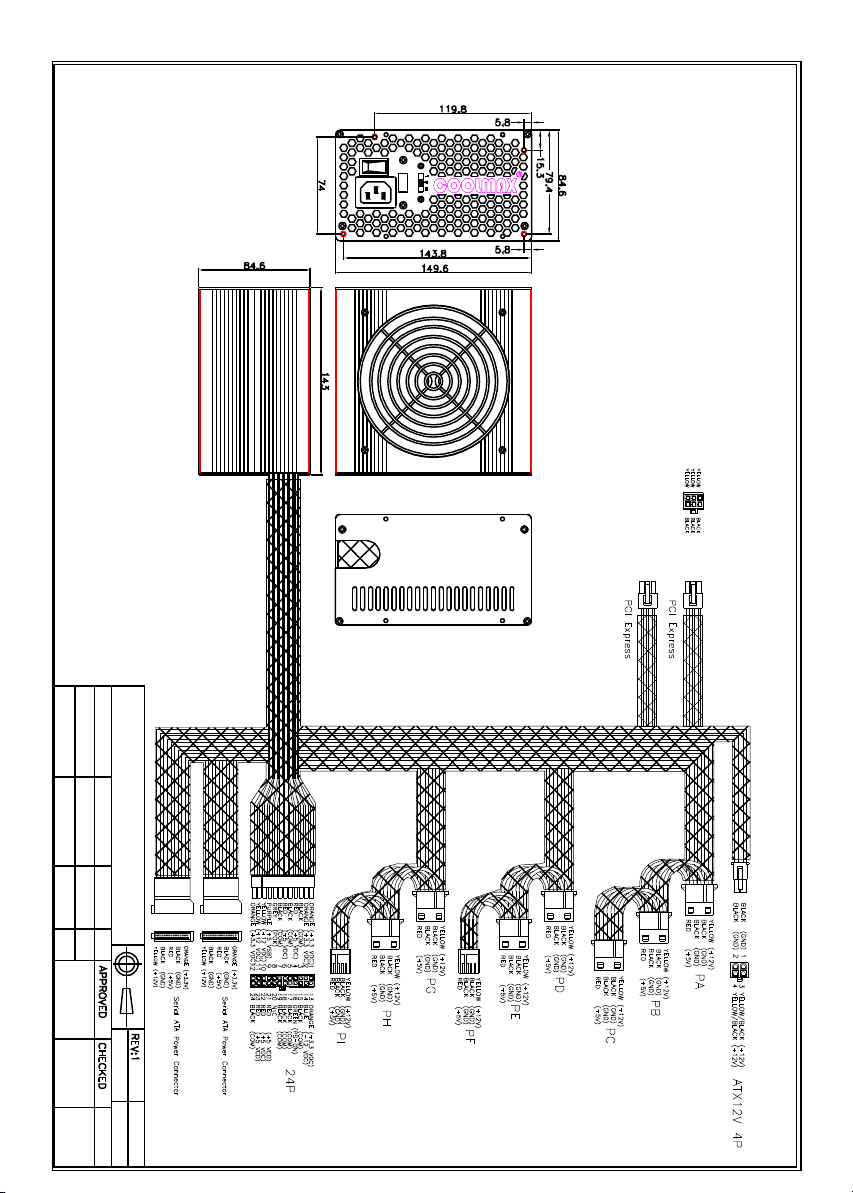
1.Actual product may slightly different from the drawing;
Nte
2.Output cables may be different in designated model on the length,connector type and/or quatity.
o:
I
O
RA NGE
FUL L
DESCRIPTION
PART NO.
MODEL
TOLERANCE
C O O L M A X TEC H N O LO G Y IN C .
CW-650T
CW
-
650T
SCALE
UNIT
NON
MM
Preliminary
DRAWN
5
Page 6
Serial ATA
Connector
+3.3VDC
COM
+5VDC
+12VDC
+3.3VDC
+3.3VDC
COM
COM
+5VDC
+5VDC
COM
COM
COM
+12VDC
+12VDC
4. Precaution
Caution: Unauthorized personnel should not do this to avoid electrical
shock!
4.1 Do not open the top cover of the power supply case.
4.2 Please keep the power supply from humidity.
5. Simple Maintenance
If power supply cannot work properly, before send for repair, please check the
following items:
5.1 Does power cord indeed plug into electrical outlet?
5.2 Does Input Voltage set in power supply correspond to the main source in your
environment?
5.3 Please check the output connectors plugging in proper direction and connecting
firmly.
5.4 Please turn off the power and turn it on for several times, and the interval must
be at least 5 minutes.
5.5 Having checked above items, if the power supply still does not function, please
send it back to your retailer or distributor for repair.
6. Mechanical Diagram
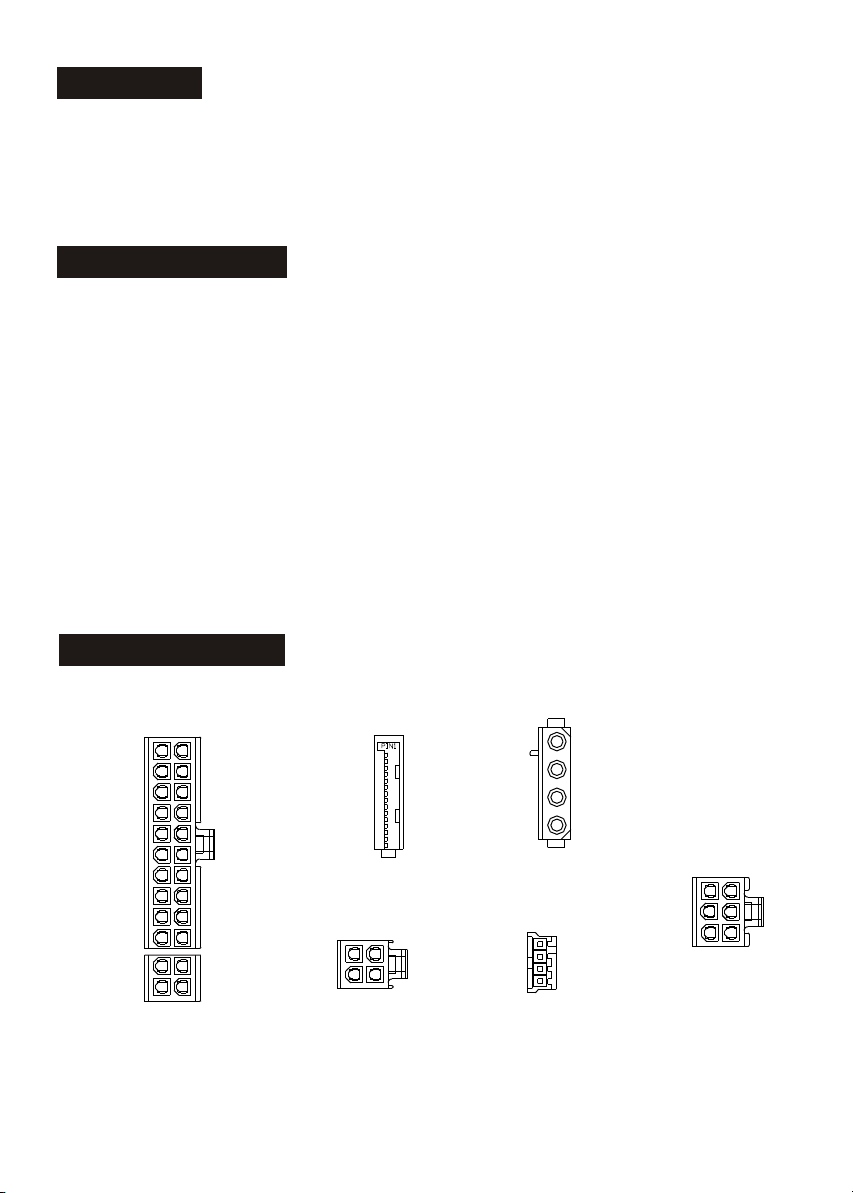
6.1 Power Connector Drawing
Pin 1
+3.3VDC
+3.3VDC
COM
+5VDC
COM
+5VDC
COM
PWR_OK
+5VSB
+12VDC
+12VDC
+3.3VDC
Main Power Connector
6.2 Overall Drawing (see attached page)
Pin 13
+3.3VDC
-12VDC
COM
PS_ON#
COM
COM
COM
N/C
+5VDC
+5VDC
+5VDC
COM
COM
COM
+12V P ower Connector
Pin 1
Pin 4
Serial ATA
Connector
Pin 3Pin 1
+12VDC
+12VDC
Peripheral Pow er
Connector
Pin 1
Pin 4
Floppy Drive
Pow er Connector
Pin-side view, not to scale
4
+12VDC
COM
COM
+5VDC
Pin1
+12VDC
+12VDC
+5VDC
COM
COM
+12VDC
+12VDC
PCI Express Connector
Pin4
COM
COM
COM
 Loading...